EP4491972A1 - Outdoor unit for refrigeration cabinet and refrigeration cabinet - Google Patents
Outdoor unit for refrigeration cabinet and refrigeration cabinet Download PDFInfo
- Publication number
- EP4491972A1 EP4491972A1 EP24187467.6A EP24187467A EP4491972A1 EP 4491972 A1 EP4491972 A1 EP 4491972A1 EP 24187467 A EP24187467 A EP 24187467A EP 4491972 A1 EP4491972 A1 EP 4491972A1
- Authority
- EP
- European Patent Office
- Prior art keywords
- unit
- bottom plate
- mode
- pipeline
- coil portion
- Prior art date
- Legal status (The legal status is an assumption and is not a legal conclusion. Google has not performed a legal analysis and makes no representation as to the accuracy of the status listed.)
- Pending
Links
Images



Classifications
-
- F—MECHANICAL ENGINEERING; LIGHTING; HEATING; WEAPONS; BLASTING
- F25—REFRIGERATION OR COOLING; COMBINED HEATING AND REFRIGERATION SYSTEMS; HEAT PUMP SYSTEMS; MANUFACTURE OR STORAGE OF ICE; LIQUEFACTION SOLIDIFICATION OF GASES
- F25B—REFRIGERATION MACHINES, PLANTS OR SYSTEMS; COMBINED HEATING AND REFRIGERATION SYSTEMS; HEAT PUMP SYSTEMS
- F25B1/00—Compression machines, plants or systems with non-reversible cycle
- F25B1/005—Compression machines, plants or systems with non-reversible cycle of the single unit type
-
- F—MECHANICAL ENGINEERING; LIGHTING; HEATING; WEAPONS; BLASTING
- F25—REFRIGERATION OR COOLING; COMBINED HEATING AND REFRIGERATION SYSTEMS; HEAT PUMP SYSTEMS; MANUFACTURE OR STORAGE OF ICE; LIQUEFACTION SOLIDIFICATION OF GASES
- F25B—REFRIGERATION MACHINES, PLANTS OR SYSTEMS; COMBINED HEATING AND REFRIGERATION SYSTEMS; HEAT PUMP SYSTEMS
- F25B41/00—Fluid-circulation arrangements
- F25B41/40—Fluid line arrangements
-
- F—MECHANICAL ENGINEERING; LIGHTING; HEATING; WEAPONS; BLASTING
- F25—REFRIGERATION OR COOLING; COMBINED HEATING AND REFRIGERATION SYSTEMS; HEAT PUMP SYSTEMS; MANUFACTURE OR STORAGE OF ICE; LIQUEFACTION SOLIDIFICATION OF GASES
- F25D—REFRIGERATORS; COLD ROOMS; ICE-BOXES; COOLING OR FREEZING APPARATUS NOT OTHERWISE PROVIDED FOR
- F25D23/00—General constructional features
-
- A—HUMAN NECESSITIES
- A47—FURNITURE; DOMESTIC ARTICLES OR APPLIANCES; COFFEE MILLS; SPICE MILLS; SUCTION CLEANERS IN GENERAL
- A47F—SPECIAL FURNITURE, FITTINGS, OR ACCESSORIES FOR SHOPS, STOREHOUSES, BARS, RESTAURANTS OR THE LIKE; PAYING COUNTERS
- A47F3/00—Show cases or show cabinets
- A47F3/04—Show cases or show cabinets air-conditioned, refrigerated
-
- F—MECHANICAL ENGINEERING; LIGHTING; HEATING; WEAPONS; BLASTING
- F24—HEATING; RANGES; VENTILATING
- F24F—AIR-CONDITIONING; AIR-HUMIDIFICATION; VENTILATION; USE OF AIR CURRENTS FOR SCREENING
- F24F1/00—Room units for air-conditioning, e.g. separate or self-contained units or units receiving primary air from a central station
- F24F1/06—Separate outdoor units, e.g. outdoor unit to be linked to a separate room comprising a compressor and a heat exchanger
- F24F1/46—Component arrangements in separate outdoor units
-
- F—MECHANICAL ENGINEERING; LIGHTING; HEATING; WEAPONS; BLASTING
- F24—HEATING; RANGES; VENTILATING
- F24F—AIR-CONDITIONING; AIR-HUMIDIFICATION; VENTILATION; USE OF AIR CURRENTS FOR SCREENING
- F24F1/00—Room units for air-conditioning, e.g. separate or self-contained units or units receiving primary air from a central station
- F24F1/06—Separate outdoor units, e.g. outdoor unit to be linked to a separate room comprising a compressor and a heat exchanger
- F24F1/60—Arrangement or mounting of the outdoor unit
-
- F—MECHANICAL ENGINEERING; LIGHTING; HEATING; WEAPONS; BLASTING
- F24—HEATING; RANGES; VENTILATING
- F24F—AIR-CONDITIONING; AIR-HUMIDIFICATION; VENTILATION; USE OF AIR CURRENTS FOR SCREENING
- F24F1/00—Room units for air-conditioning, e.g. separate or self-contained units or units receiving primary air from a central station
- F24F1/06—Separate outdoor units, e.g. outdoor unit to be linked to a separate room comprising a compressor and a heat exchanger
- F24F1/60—Arrangement or mounting of the outdoor unit
- F24F1/68—Arrangement of multiple separate outdoor units
-
- F—MECHANICAL ENGINEERING; LIGHTING; HEATING; WEAPONS; BLASTING
- F25—REFRIGERATION OR COOLING; COMBINED HEATING AND REFRIGERATION SYSTEMS; HEAT PUMP SYSTEMS; MANUFACTURE OR STORAGE OF ICE; LIQUEFACTION SOLIDIFICATION OF GASES
- F25B—REFRIGERATION MACHINES, PLANTS OR SYSTEMS; COMBINED HEATING AND REFRIGERATION SYSTEMS; HEAT PUMP SYSTEMS
- F25B1/00—Compression machines, plants or systems with non-reversible cycle
- F25B1/10—Compression machines, plants or systems with non-reversible cycle with multi-stage compression
-
- F—MECHANICAL ENGINEERING; LIGHTING; HEATING; WEAPONS; BLASTING
- F25—REFRIGERATION OR COOLING; COMBINED HEATING AND REFRIGERATION SYSTEMS; HEAT PUMP SYSTEMS; MANUFACTURE OR STORAGE OF ICE; LIQUEFACTION SOLIDIFICATION OF GASES
- F25B—REFRIGERATION MACHINES, PLANTS OR SYSTEMS; COMBINED HEATING AND REFRIGERATION SYSTEMS; HEAT PUMP SYSTEMS
- F25B40/00—Subcoolers, desuperheaters or superheaters
- F25B40/06—Superheaters
-
- F—MECHANICAL ENGINEERING; LIGHTING; HEATING; WEAPONS; BLASTING
- F25—REFRIGERATION OR COOLING; COMBINED HEATING AND REFRIGERATION SYSTEMS; HEAT PUMP SYSTEMS; MANUFACTURE OR STORAGE OF ICE; LIQUEFACTION SOLIDIFICATION OF GASES
- F25B—REFRIGERATION MACHINES, PLANTS OR SYSTEMS; COMBINED HEATING AND REFRIGERATION SYSTEMS; HEAT PUMP SYSTEMS
- F25B41/00—Fluid-circulation arrangements
- F25B41/40—Fluid line arrangements
- F25B41/42—Arrangements for diverging or converging flows, e.g. branch lines or junctions
-
- F—MECHANICAL ENGINEERING; LIGHTING; HEATING; WEAPONS; BLASTING
- F25—REFRIGERATION OR COOLING; COMBINED HEATING AND REFRIGERATION SYSTEMS; HEAT PUMP SYSTEMS; MANUFACTURE OR STORAGE OF ICE; LIQUEFACTION SOLIDIFICATION OF GASES
- F25B—REFRIGERATION MACHINES, PLANTS OR SYSTEMS; COMBINED HEATING AND REFRIGERATION SYSTEMS; HEAT PUMP SYSTEMS
- F25B43/00—Arrangements for separating or purifying gases or liquids; Arrangements for vaporising the residuum of liquid refrigerant, e.g. by heat
- F25B43/02—Arrangements for separating or purifying gases or liquids; Arrangements for vaporising the residuum of liquid refrigerant, e.g. by heat for separating lubricants from the refrigerant
-
- F—MECHANICAL ENGINEERING; LIGHTING; HEATING; WEAPONS; BLASTING
- F25—REFRIGERATION OR COOLING; COMBINED HEATING AND REFRIGERATION SYSTEMS; HEAT PUMP SYSTEMS; MANUFACTURE OR STORAGE OF ICE; LIQUEFACTION SOLIDIFICATION OF GASES
- F25D—REFRIGERATORS; COLD ROOMS; ICE-BOXES; COOLING OR FREEZING APPARATUS NOT OTHERWISE PROVIDED FOR
- F25D23/00—General constructional features
- F25D23/10—Arrangements for mounting in particular locations, e.g. for built-in type, for corner type
-
- F—MECHANICAL ENGINEERING; LIGHTING; HEATING; WEAPONS; BLASTING
- F25—REFRIGERATION OR COOLING; COMBINED HEATING AND REFRIGERATION SYSTEMS; HEAT PUMP SYSTEMS; MANUFACTURE OR STORAGE OF ICE; LIQUEFACTION SOLIDIFICATION OF GASES
- F25B—REFRIGERATION MACHINES, PLANTS OR SYSTEMS; COMBINED HEATING AND REFRIGERATION SYSTEMS; HEAT PUMP SYSTEMS
- F25B2400/00—Component parts or details not otherwise provided for in this subclass
- F25B2400/07—Details of compressors or related parts
- F25B2400/075—Details of compressors or related parts with parallel compressors
-
- F—MECHANICAL ENGINEERING; LIGHTING; HEATING; WEAPONS; BLASTING
- F25—REFRIGERATION OR COOLING; COMBINED HEATING AND REFRIGERATION SYSTEMS; HEAT PUMP SYSTEMS; MANUFACTURE OR STORAGE OF ICE; LIQUEFACTION SOLIDIFICATION OF GASES
- F25B—REFRIGERATION MACHINES, PLANTS OR SYSTEMS; COMBINED HEATING AND REFRIGERATION SYSTEMS; HEAT PUMP SYSTEMS
- F25B31/00—Compressor arrangements
- F25B31/002—Lubrication
- F25B31/004—Lubrication oil recirculating arrangements
-
- F—MECHANICAL ENGINEERING; LIGHTING; HEATING; WEAPONS; BLASTING
- F25—REFRIGERATION OR COOLING; COMBINED HEATING AND REFRIGERATION SYSTEMS; HEAT PUMP SYSTEMS; MANUFACTURE OR STORAGE OF ICE; LIQUEFACTION SOLIDIFICATION OF GASES
- F25B—REFRIGERATION MACHINES, PLANTS OR SYSTEMS; COMBINED HEATING AND REFRIGERATION SYSTEMS; HEAT PUMP SYSTEMS
- F25B39/00—Evaporators; Condensers
- F25B39/02—Evaporators
Definitions
- the present invention relates to an outdoor unit for a refrigeration cabinet, and to a refrigeration cabinet comprising the outdoor unit.
- Refrigeration cabinets such as refrigeration display cabinets, are often arranged in rows in supermarkets or convenience stores.
- a refrigeration cabinet generally includes an indoor load, i.e., a refrigeration display cabinet unit and an outdoor unit.
- a refrigeration display cabinet unit usually includes an evaporator and a throttling unit, while an outdoor unit includes components such as a compressor and a condenser.
- At least preferred embodiments of the present invention solve or at least alleviate the problems existing in the prior art.
- an outdoor unit for a refrigeration cabinet comprising:
- the first unit further comprises a regenerative heat exchanger, wherein the regenerative heat exchanger comprises a first pipeline and a second pipeline; the first unit comprising:
- the first unit comprises a first unit housing generally in the shape of a cube, the first inlet port and the first outlet port are arranged at the top of the first unit housing, wherein the first inlet port and the first outlet port are both vertically oriented upwards, the compressor, the regenerative heat exchanger and an optional oil separator, oil reservoir, refrigerant reservoir, and gas separator are arranged in the first unit housing.
- the exhaust port of the compressor is connected to the oil separator, the gas outlet of the oil separator is connected to the first outlet port, the oil outlet of the oil separator is connected to the oil reservoir, the oil reservoir is connected to the suction port of the compressor and/or the suction manifold of the compressor through capillaries, the suction port of the compressor is connected to the second end of the second pipeline of the regenerative heat exchanger via the gas separator, and the first end of the first pipeline of the regenerative heat exchanger is connected to the first inlet port via the refrigerant reservoir.
- the second unit comprises a bottom plate, a V-shaped heat exchange coil on the bottom plate, and a fan above the V-shaped heat exchange coil, wherein when installed in the first mode, the bottom plate of the second unit is installed adjacent to the top of the first unit.
- the V-shaped heat exchange coil comprises a first coil portion and a second coil portion, the first coil portion and the second coil portion each comprising an independent intake manifold, wherein each of the intake manifolds of the first coil portion and the second coil portion extends from the bottom to the top of the V-shaped heat exchange coil along one side of the first coil portion and the second coil portion respectively, and each comprises an independent intake port, while the return manifolds of the first coil portion and the second coil portion converge to a return header that is vertically oriented and has a vertically downward return port.
- the bottom plate of the second unit comprises a bottom plate body supporting the bottom of the V-shaped heat exchange coil and a bottom plate frame outerside of the bottom plate body; the second unit further comprises grid plates on both sides and end plates at both ends connected between the bottom plate frame and the top of the V-shaped heat exchange coil, making the second unit generally in the shape of a cube; the size and shape of the bottom plate frame are substantially the same as the size and shape of the top of the first unit; the top of the first unit has a positioning feature matching the bottom plate body and/or bottom plate frame of the second unit; the first unit and the second unit as a whole, when installed in the first mode, are generally in the shape of a cube.
- the first unit is connected to the second unit through a plurality of bolts arranged along the bottom plate body and/or the bottom plate frame, and the grid plates are installed after the assembly of the first unit and the second unit.
- the second unit is further configured with an electronic control module, where when installed in the second mode, an integrated electrical cable is connected between the first unit and the electronic control module of the second unit.
- a refrigeration cabinet comprising the outdoor unit according to the first aspect, optionally including any of the optional features thereof.
- the outdoor unit and refrigeration cabinet according to the embodiments of the present invention provide more flexible installation options for outdoor units, where the outdoor units can be installed according to different on-site conditions.
- an outdoor unit for a refrigeration cabinet which comprises: a first unit 1 comprising a compressor, such as a single compressor or two (or more) compressors 911, 912 connected in parallel; a second unit 2 comprising a condenser, for example, the condenser comprises two sets of coils 221, 222 and two fans 23.
- the outdoor unit can be installed in a first mode or a second mode. In the first mode as shown in FIG. 1 , the first unit 1 and the second unit 2 are installed adjacent to each other and connected with each other through fasteners, and the first unit 1 and the second unit 2 are connected through a first fluid pipeline passing through the adjacent surface between the first unit and the second unit.
- the outdoor unit In the second mode, the first unit 1 and the second unit 2 are respectively installed at a first position and a second position spaced apart from each other, and the first unit 1 and the second unit 2 are connected through a second fluid pipeline extending between the first position and the second position. Therefore, the outdoor unit according to the embodiment of the present invention provides two installation modes. In the first installation mode, the first unit 1 with a compressor and the second unit 2 with a condenser are configured in combination. The first mode is applicable to the working condition with good installation conditions. Whereas, in the second mode, the first unit 1 and the second unit 2 are arranged at different positions. This installation mode is applicable to the situation with limited installation conditions.
- the first unit 1 can be installed at the first position near the indoor load but with poor ventilation, while the second unit 2 is installed at the second position with better ventilation but far away. Therefore, the outdoor unit according to the embodiments of the present invention provides installation flexibility, enabling the outdoor unit to flexibly adapt to various installation conditions. For example, outdoor units can be transported to the site in the first installation mode, and then installed in the first mode or the second mode according to on-site conditions.
- the first unit 1 further comprises a regenerative heat exchanger 96, which comprises a first pipeline 961 and a second pipeline 962.
- the first unit 1 comprises: a first outlet port 120 connected to exhaust ports 913, 915 of the compressors, and a first inlet port 121 connected to the first end of the first pipeline 961 of the regenerative heat exchanger 96; a second outlet port 127 connected to the second end of the first pipeline 961 of the regenerative heat exchanger 96; and a second inlet port 128 connected to the first end of the second pipeline 962 of the regenerative heat exchanger 96.
- the second end of the second pipeline 962 of the regenerative heat exchanger 96 is connected to suction ports 914, 916 of the compressors.
- the first inlet port 121 and the first outlet port 120 are respectively used to connect to the condenser of the second unit 2, i.e., the inlet and outlet of the condenser.
- the second inlet port 128 and the second outlet port 127 are respectively used to connect to the indoor load, i.e., the indoor load comprises a throttling unit and an evaporator.
- the first unit 1 of the outdoor unit according to the embodiment of the present invention is provided with a regenerative heat exchanger 96, which is particularly important in the second mode.
- the pipeline between the first unit 1 and the second unit 2 may be relatively long and exposed to outdoors, this may cause part of the liquid refrigerant from the condenser outlet to evaporate before reaching the first unit 1 through the long pipeline and generate two-phase refrigerant.
- the refrigerant returned from the second pipeline 962 in the regenerative heat exchanger 96 By exchanging heat with the refrigerant returned from the second pipeline 962 in the regenerative heat exchanger 96, the supercooling of the refrigerant in the first pipeline 961 and the superheat of the refrigerant in the second pipeline 962 will be increased, so as to avoid or at least mitigate the impact of two-phase refrigerant on the performance of the indoor load when it is transported to the indoor load.
- the first unit 1 comprises a first unit housing generally in the shape of a cube, comprising a top 12, a peripheral wall, and a bottom wall.
- An openable double door 11 can be provided at one end of the peripheral wall for purposes like maintenance. It can be seen from FIGS. 2 and 3 that the first outlet port 120 and the first inlet port 121 are provided at the top 12 of the first unit housing.
- Compressors 911, 912, the regenerative heat exchanger 96 and an optional oil separator 92, oil reservoir 93, refrigerant reservoir 94, and gas separator 95 are also installed in the first unit housing.
- the second unit 2 is marked by a box, and the remaining parts outside the box belong to the first unit 1.
- the compressor exhaust ports 913, 915 of the two parallel compressors 911, 912 are connected to the oil separator 92, and the gas outlet 921 of the oil separator is connected to the first outlet port 120.
- two parallel first outlet ports 120 are provided (alternatively, the number of first outlet ports 120 can be changed).
- the oil outlet 922 of the oil separator 92 is connected to the oil reservoir 93.
- the oil reservoir 93 is further connected to the compressor suction ports 914, 916 and/or the compressor suction manifold 917 through capillaries.
- the compressor suction ports 914, 916 are connected to the second end of the second pipeline 962 of the regenerative heat exchanger 96 via the gas separator 95.
- the first end of the first pipeline 961 of the regenerative heat exchanger 96 is connected to the first inlet port 121 via the refrigerant reservoir 94.
- the second unit 2 comprises a bottom plate, a V-shaped heat exchange coil 221, 222 on the bottom plate, and two fans 23 above the V-shaped heat exchange coil 221, 222 (alternatively, the number of fans 23 can be changed).
- the bottom plate of the second unit When installed in the first mode, the bottom plate of the second unit is installed adjacent to the top 12 of the first unit.
- the fan 23 comprises a motor, blades, and grills. During operation, the fan draws air from both sides which allows the airflow to pass through the V-shaped heat exchange coil 221, 222, and then dissipates from the top after exchanging heat with the refrigerant in the heat exchange coil 221, 222.
- the V-shaped heat exchange coil comprises a first coil portion 221 and a second coil portion 222 independent of each other, with the first coil portion 221 and the second coil portion 222 being plate-like, respectively and arranged in a V-shaped manner.
- the first coil portion 221 and the second coil portion 222 each includes an independent intake manifold 226, which extends from the bottom to the top along one side of the first coil portion 221 and the second coil portion 222, and each includes independent inlet ports.
- each inlet port is connected to the first outlet port 120 of the first unit through an L-shaped pipe 31, while the return liquid of the first coil portion 221 and the second coil portion 222 converges and connects to the return header 225 through the return manifold 224.
- the return header 225 is generally T-shaped and includes a vertically oriented part, where the vertically oriented part has a downward return liquid port.
- the return liquid port is connected with the first inlet port 121 of the first unit 1, which is also vertically oriented, so that the liquid refrigerant can return back to the first unit 1 by gravity.
- the bottom plate of the second unit comprises a bottom plate body 21 supporting the bottom of the V-shaped heat exchange coil and a bottom plate frame 211, 212 outerside of the bottom plate body 21.
- the bottom plate frame is generally rectangular and comprise transverse frames 212 and longitudinal frames 211.
- vertical beams 223 are also provided at the four corners of the bottom plate frame.
- the second unit 2 may further comprise grid plates 29 on both sides and end plates 28 at both ends connected between the bottom plate frame and the top of the V-shaped heat exchange coil, so that the second unit is generally in the shape of a cube.
- the size and shape of the bottom plate frame of the second unit 2 are basically the same as the size and shape of the top 12 of the first unit 1, so that the outdoor unit is generally in the shape of a cube after the first unit 1 and the second unit 2 are assembled in the first mode, thereby facilitating the outdoor unit assembled in the first mode to be placed in a regular outdoor installation space.
- the frame of the bottom plate of the second unit when installed in the first mode, can be connected to the first unit through a plurality of bolts 3.
- a plurality of bolts can also be used to connect the bottom plate body of the second unit 2 and the first unit.
- the grid plates 29 can be installed after assembly of the first unit and the second unit using the plurality of bolts 3.
- the first unit 1 and the second unit 2 when installed in the first mode, can be directly assembled by inserting a short fluid pipeline, such as the L-shaped fluid pipeline 31 as shown.
- the control cable for the fan of the condenser of the second unit 2 can be easily connected between the first unit and the second unit.
- the second unit 2 when the first unit 1 and the second unit 2 are installed in the second mode, the second unit 2 can be configured with an electronic control module 27.
- the electrical lines between the first unit 1 and the second unit 2 can be integrated into a single electrical cable and connected to the electronic control module 27 of the second unit, thus facilitating the regulation and arrangement of long-distance electrical lines.
- the electrical cable and fluid pipeline when installed in the second mode, can also be integrated into one integrated line.
- the top of the first unit 1 may have a positioning feature 17 that matches the bottom plate frame or bottom plate body of the second unit, thereby facilitating the assembly of both.
- a refrigeration cabinet comprising the outdoor unit according to the respective embodiments is further provided.
- the outdoor unit according to the present invention can be transported to the site in the first mode (alternatively, it can also be transported in a split manner), and then determined to be installed in the first mode or in the second mode based on on-site conditions.
- the installation in the first mode only requires welding the corresponding pipelines, and installing fasteners and electrical lines.
- the installation in the second mode may consider to use a single mixed line including electrical connection and fluid communication to be reasonably arranged and connected between the first unit 1 and the second unit 2.
- the outdoor unit is usually arranged outdoors, but this is not restrictive. In fact, outdoor unit is only intended to indicate that it can be in a different space relative to the indoor load, rather than that it must be exposed to the outdoor environment.
- the first unit 1 can also be arranged in a space indoors that is different from the space of the indoor load, or the first unit 1 and the second unit 2 can be jointly arranged in spaces indoors that are different from the space of the indoor load.
Landscapes
- Engineering & Computer Science (AREA)
- Mechanical Engineering (AREA)
- General Engineering & Computer Science (AREA)
- Physics & Mathematics (AREA)
- Thermal Sciences (AREA)
- Chemical & Material Sciences (AREA)
- Combustion & Propulsion (AREA)
- Analytical Chemistry (AREA)
- Power Engineering (AREA)
- Other Air-Conditioning Systems (AREA)
Abstract
An outdoor unit for a refrigeration cabinet comprises: a first unit (1) comprising a compressor; a second unit (2) comprising a condenser; wherein, the outdoor unit is configured to be installed in a first mode or a second mode; where in the first mode, the first unit (1) and the second unit (2) are installed adjacent to each other and connected with each other through fasteners, and the first unit and the second unit are connected through a first fluid pipeline passing through an adjacent surface between the first unit and the second unit; where in the second mode, the first unit (1) and the second unit (2) are respectively installed at a first position and a second position spaced apart from each other, and the first unit and the second unit are connected through a second fluid pipeline extending between the first position and the second position. The outdoor unit and refrigeration cabinet according to the embodiments of the present invention provide more flexible installation options for outdoor units, where the outdoor units can be installed according to different on-site conditions.
Description
- The present invention relates to an outdoor unit for a refrigeration cabinet, and to a refrigeration cabinet comprising the outdoor unit.
- Refrigeration cabinets, such as refrigeration display cabinets, are often arranged in rows in supermarkets or convenience stores. A refrigeration cabinet generally includes an indoor load, i.e., a refrigeration display cabinet unit and an outdoor unit. A refrigeration display cabinet unit usually includes an evaporator and a throttling unit, while an outdoor unit includes components such as a compressor and a condenser.
- In field installation of a refrigeration cabinet, due to limitations of outdoor installation space and conditions, it may not be possible to install the entire outdoor unit as a whole in a location close to the indoor unit. In this circumstance, longer pipelines need to be arranged, and the pipelines between the outdoor unit and the indoor load usually employ large-diameter copper pipes, which are costly and difficult to install.
- At least preferred embodiments of the present invention solve or at least alleviate the problems existing in the prior art.
- According to a first aspect of the present invention, an outdoor unit for a refrigeration cabinet is provided, comprising:
- a first unit comprising a compressor;
- a second unit comprising a condenser;
- wherein, the outdoor unit is configured to be installed in a first mode or a second mode;
- where in the first mode, the first unit and the second unit are installed adjacent to each other and connected with each other through fasteners, and the first unit and the second unit are connected through a first fluid pipeline passing through an adjacent surface between the first unit and the second unit;
- where in the second mode, the first unit and the second unit are respectively installed at a first position and a second position spaced apart from each other, and the first unit and the second unit are connected through a second fluid pipeline extending between the first position and the second position.
- Optionally, the first unit further comprises a regenerative heat exchanger, wherein the regenerative heat exchanger comprises a first pipeline and a second pipeline;
the first unit comprising: - a first outlet port connected to an exhaust port of the compressor;
- a first inlet port connected to a first end of the first pipeline of the regenerative heat exchanger;
- a second outlet port connected to a second end of the first pipeline of the regenerative heat exchanger; and
- a second inlet port connected to a first end of the second pipeline of the regenerative heat exchanger;
- wherein, the second end of the second pipeline of the regenerative heat exchanger is connected to a suction port of the compressor, the first inlet port and the first outlet port are respectively configured to connect to the condenser of the second unit, and the second inlet port and the second outlet port are respectively configured to connect to an indoor load.
- Optionally, the first unit comprises a first unit housing generally in the shape of a cube, the first inlet port and the first outlet port are arranged at the top of the first unit housing, wherein the first inlet port and the first outlet port are both vertically oriented upwards, the compressor, the regenerative heat exchanger and an optional oil separator, oil reservoir, refrigerant reservoir, and gas separator are arranged in the first unit housing.
- Optionally, in the first unit, the exhaust port of the compressor is connected to the oil separator, the gas outlet of the oil separator is connected to the first outlet port, the oil outlet of the oil separator is connected to the oil reservoir, the oil reservoir is connected to the suction port of the compressor and/or the suction manifold of the compressor through capillaries, the suction port of the compressor is connected to the second end of the second pipeline of the regenerative heat exchanger via the gas separator, and the first end of the first pipeline of the regenerative heat exchanger is connected to the first inlet port via the refrigerant reservoir.
- Optionally, the second unit comprises a bottom plate, a V-shaped heat exchange coil on the bottom plate, and a fan above the V-shaped heat exchange coil, wherein when installed in the first mode, the bottom plate of the second unit is installed adjacent to the top of the first unit.
- Optionally, the V-shaped heat exchange coil comprises a first coil portion and a second coil portion, the first coil portion and the second coil portion each comprising an independent intake manifold, wherein each of the intake manifolds of the first coil portion and the second coil portion extends from the bottom to the top of the V-shaped heat exchange coil along one side of the first coil portion and the second coil portion respectively, and each comprises an independent intake port, while the return manifolds of the first coil portion and the second coil portion converge to a return header that is vertically oriented and has a vertically downward return port.
- Optionally, the bottom plate of the second unit comprises a bottom plate body supporting the bottom of the V-shaped heat exchange coil and a bottom plate frame outerside of the bottom plate body; the second unit further comprises grid plates on both sides and end plates at both ends connected between the bottom plate frame and the top of the V-shaped heat exchange coil, making the second unit generally in the shape of a cube; the size and shape of the bottom plate frame are substantially the same as the size and shape of the top of the first unit; the top of the first unit has a positioning feature matching the bottom plate body and/or bottom plate frame of the second unit; the first unit and the second unit as a whole, when installed in the first mode, are generally in the shape of a cube.
- Optionally, in the first mode, the first unit is connected to the second unit through a plurality of bolts arranged along the bottom plate body and/or the bottom plate frame, and the grid plates are installed after the assembly of the first unit and the second unit.
- Optionally, the second unit is further configured with an electronic control module, where when installed in the second mode, an integrated electrical cable is connected between the first unit and the electronic control module of the second unit.
- According to another aspect, a refrigeration cabinet is provided, comprising the outdoor unit according to the first aspect, optionally including any of the optional features thereof.
- The outdoor unit and refrigeration cabinet according to the embodiments of the present invention provide more flexible installation options for outdoor units, where the outdoor units can be installed according to different on-site conditions.
- With reference to the accompanying drawings, the invention will become easier to understand. Those skilled in the art would easily understand that these drawings are for the purpose of illustration, and are not intended to limit the scope of protection of the present invention. In addition, in the figures, similar numerals are used to denote similar components, where:
-
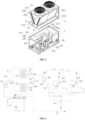
FIG. 1 shows a three-dimensional view of an outdoor unit for a refrigeration cabinet installed in a first mode; -
FIG. 2 shows an exploded view of an outdoor unit for a refrigeration cabinet; -
FIG. 3 shows an internal structural view of an outdoor unit for a refrigeration cabinet; -
FIG. 4 shows a flow path structure diagram of an outdoor unit for a refrigeration cabinet; -
FIG. 5 shows an exploded view of an outdoor unit for a refrigeration cabinet; and -
FIGS. 6 and7 respectively show a three-dimensional view of an outdoor unit for a refrigeration cabinet, and a partially enlarged view of area A inside. - Referring to
FIGS. 1 to 4 , an outdoor unit for a refrigeration cabinet according to an embodiment of the present invention is described, which comprises: afirst unit 1 comprising a compressor, such as a single compressor or two (or more)compressors second unit 2 comprising a condenser, for example, the condenser comprises two sets ofcoils fans 23. The outdoor unit can be installed in a first mode or a second mode. In the first mode as shown inFIG. 1 , thefirst unit 1 and thesecond unit 2 are installed adjacent to each other and connected with each other through fasteners, and thefirst unit 1 and thesecond unit 2 are connected through a first fluid pipeline passing through the adjacent surface between the first unit and the second unit. In the second mode, thefirst unit 1 and thesecond unit 2 are respectively installed at a first position and a second position spaced apart from each other, and thefirst unit 1 and thesecond unit 2 are connected through a second fluid pipeline extending between the first position and the second position. Therefore, the outdoor unit according to the embodiment of the present invention provides two installation modes. In the first installation mode, thefirst unit 1 with a compressor and thesecond unit 2 with a condenser are configured in combination. The first mode is applicable to the working condition with good installation conditions. Whereas, in the second mode, thefirst unit 1 and thesecond unit 2 are arranged at different positions. This installation mode is applicable to the situation with limited installation conditions. For example, thefirst unit 1 can be installed at the first position near the indoor load but with poor ventilation, while thesecond unit 2 is installed at the second position with better ventilation but far away. Therefore, the outdoor unit according to the embodiments of the present invention provides installation flexibility, enabling the outdoor unit to flexibly adapt to various installation conditions. For example, outdoor units can be transported to the site in the first installation mode, and then installed in the first mode or the second mode according to on-site conditions. - In some embodiments, referring to
FIGS. 3 and 4 , thefirst unit 1 further comprises aregenerative heat exchanger 96, which comprises afirst pipeline 961 and asecond pipeline 962. Thefirst unit 1 comprises: afirst outlet port 120 connected toexhaust ports first inlet port 121 connected to the first end of thefirst pipeline 961 of theregenerative heat exchanger 96; asecond outlet port 127 connected to the second end of thefirst pipeline 961 of theregenerative heat exchanger 96; and asecond inlet port 128 connected to the first end of thesecond pipeline 962 of theregenerative heat exchanger 96. The second end of thesecond pipeline 962 of theregenerative heat exchanger 96 is connected tosuction ports first inlet port 121 and thefirst outlet port 120 are respectively used to connect to the condenser of thesecond unit 2, i.e., the inlet and outlet of the condenser. Thesecond inlet port 128 and thesecond outlet port 127 are respectively used to connect to the indoor load, i.e., the indoor load comprises a throttling unit and an evaporator. Thefirst unit 1 of the outdoor unit according to the embodiment of the present invention is provided with aregenerative heat exchanger 96, which is particularly important in the second mode. Specifically, during installation in the second mode, because the pipeline between thefirst unit 1 and thesecond unit 2 may be relatively long and exposed to outdoors, this may cause part of the liquid refrigerant from the condenser outlet to evaporate before reaching thefirst unit 1 through the long pipeline and generate two-phase refrigerant. By exchanging heat with the refrigerant returned from thesecond pipeline 962 in theregenerative heat exchanger 96, the supercooling of the refrigerant in thefirst pipeline 961 and the superheat of the refrigerant in thesecond pipeline 962 will be increased, so as to avoid or at least mitigate the impact of two-phase refrigerant on the performance of the indoor load when it is transported to the indoor load. - In some embodiments, the
first unit 1 comprises a first unit housing generally in the shape of a cube, comprising atop 12, a peripheral wall, and a bottom wall. An openabledouble door 11 can be provided at one end of the peripheral wall for purposes like maintenance. It can be seen fromFIGS. 2 and3 that thefirst outlet port 120 and thefirst inlet port 121 are provided at the top 12 of the first unit housing.Compressors regenerative heat exchanger 96 and anoptional oil separator 92,oil reservoir 93,refrigerant reservoir 94, andgas separator 95 are also installed in the first unit housing. - In some embodiments, referring to
FIG. 4 , thesecond unit 2 is marked by a box, and the remaining parts outside the box belong to thefirst unit 1. In this embodiment, thecompressor exhaust ports parallel compressors 911, 912 (alternatively, the number of compressors can be changed) are connected to theoil separator 92, and thegas outlet 921 of the oil separator is connected to thefirst outlet port 120. In the embodiment illustrated, two parallelfirst outlet ports 120 are provided (alternatively, the number offirst outlet ports 120 can be changed). Theoil outlet 922 of theoil separator 92 is connected to theoil reservoir 93. Theoil reservoir 93 is further connected to thecompressor suction ports compressor suction manifold 917 through capillaries. Thecompressor suction ports second pipeline 962 of theregenerative heat exchanger 96 via thegas separator 95. The first end of thefirst pipeline 961 of theregenerative heat exchanger 96 is connected to thefirst inlet port 121 via therefrigerant reservoir 94. - In some embodiments, as shown in
FIG. 3 , thesecond unit 2 comprises a bottom plate, a V-shapedheat exchange coil fans 23 above the V-shapedheat exchange coil 221, 222 (alternatively, the number offans 23 can be changed). When installed in the first mode, the bottom plate of the second unit is installed adjacent to the top 12 of the first unit. Thefan 23 comprises a motor, blades, and grills. During operation, the fan draws air from both sides which allows the airflow to pass through the V-shapedheat exchange coil heat exchange coil second unit 2, even when thesecond unit 2 is installed above thefirst unit 1 in the first mode, the operation of thesecond unit 2 will not be hindered. - In some embodiments, the V-shaped heat exchange coil comprises a
first coil portion 221 and asecond coil portion 222 independent of each other, with thefirst coil portion 221 and thesecond coil portion 222 being plate-like, respectively and arranged in a V-shaped manner. Thefirst coil portion 221 and thesecond coil portion 222 each includes anindependent intake manifold 226, which extends from the bottom to the top along one side of thefirst coil portion 221 and thesecond coil portion 222, and each includes independent inlet ports. In the first mode, each inlet port is connected to thefirst outlet port 120 of the first unit through an L-shapedpipe 31, while the return liquid of thefirst coil portion 221 and thesecond coil portion 222 converges and connects to thereturn header 225 through thereturn manifold 224. Thereturn header 225 is generally T-shaped and includes a vertically oriented part, where the vertically oriented part has a downward return liquid port. In the first mode, the return liquid port is connected with thefirst inlet port 121 of thefirst unit 1, which is also vertically oriented, so that the liquid refrigerant can return back to thefirst unit 1 by gravity. - In some embodiments, the bottom plate of the second unit comprises a
bottom plate body 21 supporting the bottom of the V-shaped heat exchange coil and abottom plate frame bottom plate body 21. In the embodiment illustrated, the bottom plate frame is generally rectangular and comprisetransverse frames 212 andlongitudinal frames 211. In addition, for structural stability,vertical beams 223 are also provided at the four corners of the bottom plate frame. As shown inFIG. 1 , in some embodiments, thesecond unit 2 may further comprisegrid plates 29 on both sides andend plates 28 at both ends connected between the bottom plate frame and the top of the V-shaped heat exchange coil, so that the second unit is generally in the shape of a cube. The size and shape of the bottom plate frame of thesecond unit 2 are basically the same as the size and shape of the top 12 of thefirst unit 1, so that the outdoor unit is generally in the shape of a cube after thefirst unit 1 and thesecond unit 2 are assembled in the first mode, thereby facilitating the outdoor unit assembled in the first mode to be placed in a regular outdoor installation space. - In some embodiments, as shown in
FIG. 2 , when installed in the first mode, the frame of the bottom plate of the second unit can be connected to the first unit through a plurality ofbolts 3. Alternatively, a plurality of bolts can also be used to connect the bottom plate body of thesecond unit 2 and the first unit. Thegrid plates 29 can be installed after assembly of the first unit and the second unit using the plurality ofbolts 3. In addition, when installed in the first mode, thefirst unit 1 and thesecond unit 2 can be directly assembled by inserting a short fluid pipeline, such as the L-shapedfluid pipeline 31 as shown. Furthermore, the control cable for the fan of the condenser of thesecond unit 2 can be easily connected between the first unit and the second unit. In other embodiments, when thefirst unit 1 and thesecond unit 2 are installed in the second mode, thesecond unit 2 can be configured with anelectronic control module 27. In this circumstance, the electrical lines between thefirst unit 1 and thesecond unit 2 can be integrated into a single electrical cable and connected to theelectronic control module 27 of the second unit, thus facilitating the regulation and arrangement of long-distance electrical lines. In some embodiments, when installed in the second mode, the electrical cable and fluid pipeline can also be integrated into one integrated line. In some embodiments, as shown inFIGS. 6 and7 , the top of thefirst unit 1 may have apositioning feature 17 that matches the bottom plate frame or bottom plate body of the second unit, thereby facilitating the assembly of both. According to other embodiments, a refrigeration cabinet comprising the outdoor unit according to the respective embodiments is further provided. - The outdoor unit according to the present invention can be transported to the site in the first mode (alternatively, it can also be transported in a split manner), and then determined to be installed in the first mode or in the second mode based on on-site conditions. The installation in the first mode only requires welding the corresponding pipelines, and installing fasteners and electrical lines. The installation in the second mode may consider to use a single mixed line including electrical connection and fluid communication to be reasonably arranged and connected between the
first unit 1 and thesecond unit 2. It should be appreciated that the outdoor unit is usually arranged outdoors, but this is not restrictive. In fact, outdoor unit is only intended to indicate that it can be in a different space relative to the indoor load, rather than that it must be exposed to the outdoor environment. For example, thefirst unit 1 can also be arranged in a space indoors that is different from the space of the indoor load, or thefirst unit 1 and thesecond unit 2 can be jointly arranged in spaces indoors that are different from the space of the indoor load. - The specific embodiments described above are merely intended to describe the principles of the present invention more clearly, wherein various components are clearly shown or described to facilitate the understanding of the principles of the present invention. Those skilled in the art may, without departing from the scope of the present invention, make various modifications or changes. Therefore, it should be understood that these modifications or changes should be included within the scope of patent protection, as defined by the appended claims.
Claims (10)
- An outdoor unit for a refrigeration cabinet, comprising:a first unit (1) comprising a compressor (911, 912);a second unit (2) comprising a condenser;wherein, the outdoor unit is configured to be installed in a first mode or a second mode;where in the first mode, the first unit (1) and the second unit (2) are installed adjacent to each other and connected with each other through fasteners (3), and the first unit and the second unit are connected through a first fluid pipeline passing through an adjacent surface between the first unit and the second unit;where in the second mode, the first unit (1) and the second unit (2) are respectively installed at a first position and a second position spaced apart from each other, and the first unit and the second unit are connected through a second fluid pipeline (31) extending between the first position and the second position.
- The outdoor unit according to claim 1, wherein the first unit (1) further comprises a regenerative heat exchanger (96), and the regenerative heat exchanger comprises a first pipeline (961) and a second pipeline (962);
the first unit comprising:a first outlet port (120) connected to an exhaust port (913, 915) of the compressor (911, 912);a first inlet port (121) connected to a first end of the first pipeline (961) of the regenerative heat exchanger (96);a second outlet port (127) connected to a second end of the first pipeline (961) of the regenerative heat exchanger (96); anda second inlet port (128) connected to a first end of the second pipeline (962) of the regenerative heat exchanger (96);wherein, the second end of the second pipeline (962) of the regenerative heat exchanger (96) is connected to a suction port (914, 916) of the compressor, the first inlet port (121) and the first outlet port (120) are configured to connect to the condenser of the second unit respectively, and the second inlet port (128) and the second outlet port (127) are configured to connect to an indoor load respectively. - The outdoor unit according to claim 2, wherein the first unit (1) comprises a first unit housing generally in the shape of a cube, the first inlet port (121) and the first outlet port (120) are arranged at the top (12) of the first unit housing, the first inlet port and the first outlet port are both vertically oriented upwards, and the compressor (911, 912), the regenerative heat exchanger (96) and an optional oil separator (92), oil reservoir (93), refrigerant reservoir (94), and gas separator (95) are arranged in the first unit housing.
- The outdoor unit according to claim 3, wherein in the first unit, the exhaust port (913, 915) of the compressor (911, 912) is connected to the oil separator (92), a gas outlet (921) of the oil separator is connected to the first outlet port (120), an oil outlet (922) of the oil separator is connected to the oil reservoir (93), the oil reservoir is connected to the suction port (914, 916) of the compressor and/or a suction manifold (917) of the compressor through capillaries, the suction port (914, 916) of the compressor is connected to the second end of the second pipeline (962) of the regenerative heat exchanger (96) via the gas separator (95), and the first end of the first pipeline (961) of the regenerative heat exchanger (96) is connected to the first inlet port (121) via the refrigerant reservoir (94).
- The outdoor unit according to any of claims 1-4, wherein the second unit (2) comprises a bottom plate, a V-shaped heat exchange coil (221, 222) on the bottom plate, and a fan (23) above the V-shaped heat exchange coil, where when installed in the first mode, the bottom plate of the second unit (2) is installed adjacent to the top (12) of the first unit (1).
- The outdoor unit according to claim 5, wherein the V-shaped heat exchange coil comprises a first coil portion (221) and a second coil portion (222), with the first coil portion and the second coil portion being plate-like respectively and arranged in a V-shaped manner, and the first coil portion (221) and the second coil portion (222) each comprises an independent intake manifold (226), where each of the intake manifolds of the first coil portion and the second coil portion extends from the bottom to the top of the coil along one side of the first coil portion (221) and the second coil portion (222) respectively, and each comprises an independent inlet port, while return manifolds (224) of the first coil portion and the second coil portion converge to a return header (225) that is vertically oriented and has a vertically downward return port.
- The outdoor unit according to claim 5 or 6, wherein the bottom plate of the second unit comprises a bottom plate body (21) supporting the bottom of the V-shaped heat exchange coil (221, 222) and a bottom plate frame (211, 212) outerside of the bottom plate body; the second unit (2) further comprises grid plates (29) on both sides and end plates (28) at both ends connected between the bottom plate frame (211, 212) and the top of the V-shaped heat exchange coil, making the second unit (2) generally in the shape of a cube; a size and shape of the bottom plate frame (211, 212) are substantially the same as size and shape of the top (12) of the first unit (1); the top of the first unit (1) has a positioning feature (17) matching the bottom plate body (21) and/or bottom plate frame (211, 212) of the second unit; the first unit (1) and the second unit (2) as a whole, when installed in the first mode, are generally in the shape of a cube.
- The outdoor unit according to claim 7, wherein in the first mode, the first unit (1) is connected to the second unit (2) through a plurality of bolts (3) arranged along the bottom plate body (21) and/or the bottom plate frame (211, 212), and the grid plates (29) are installed after assembly of the first unit and the second unit.
- The outdoor unit according to any of claims 1-8, wherein the second unit (2) is further configured with an electronic control module (27), where when installed in the second mode, an integrated electrical cable is connected between the first unit (1) and the electronic control module (27) of the second unit (2).
- A refrigeration cabinet, wherein the refrigeration cabinet comprises an outdoor unit according to any of claims 1-9.
Applications Claiming Priority (1)
| Application Number | Priority Date | Filing Date | Title |
|---|---|---|---|
| CN202310843002.6A CN119289585A (en) | 2023-07-10 | 2023-07-10 | Outdoor unit for refrigerator device and refrigerator device |
Publications (1)
| Publication Number | Publication Date |
|---|---|
| EP4491972A1 true EP4491972A1 (en) | 2025-01-15 |
Family
ID=91898815
Family Applications (1)
| Application Number | Title | Priority Date | Filing Date |
|---|---|---|---|
| EP24187467.6A Pending EP4491972A1 (en) | 2023-07-10 | 2024-07-09 | Outdoor unit for refrigeration cabinet and refrigeration cabinet |
Country Status (3)
| Country | Link |
|---|---|
| US (1) | US20250020366A1 (en) |
| EP (1) | EP4491972A1 (en) |
| CN (1) | CN119289585A (en) |
Citations (5)
| Publication number | Priority date | Publication date | Assignee | Title |
|---|---|---|---|---|
| JPH0749875B2 (en) * | 1985-08-31 | 1995-05-31 | ヤマハ発動機株式会社 | Engine driven heat pump type air conditioner |
| JPH09229423A (en) * | 1996-02-26 | 1997-09-05 | Sanyo Electric Co Ltd | Freezer device |
| JP2002243208A (en) * | 2001-02-14 | 2002-08-28 | Sanyo Electric Co Ltd | Remote capacitor |
| EP3964754A1 (en) * | 2020-09-07 | 2022-03-09 | LG Electronics Inc. | Air conditioner |
| US20230152017A1 (en) * | 2021-11-18 | 2023-05-18 | Airsys Refrigeration Engineering Technology (Beijing) Co. Ltd. | Refrigeration System and Control Method of Refrigeration System |
Family Cites Families (22)
| Publication number | Priority date | Publication date | Assignee | Title |
|---|---|---|---|---|
| KR100852645B1 (en) * | 2001-02-23 | 2008-08-18 | 브룩스 오토메이션 인코퍼레이티드 | Cryogenic Closed Loop Recirculating Gas Cooling Unit |
| WO2008124637A2 (en) * | 2007-04-05 | 2008-10-16 | Johnson Controls Technology Company | Heat exchanger |
| US8413461B2 (en) * | 2007-07-24 | 2013-04-09 | Johnson Controls Technology Company | Auxiliary cooling system |
| MY188565A (en) * | 2009-07-28 | 2021-12-22 | Toshiba Carrier Corp | Heat source unit |
| EP3264003B1 (en) * | 2010-02-08 | 2024-11-27 | Johnson Controls Tyco IP Holdings LLP | Vapor compression system |
| KR101281230B1 (en) * | 2010-10-27 | 2013-07-02 | 엘지전자 주식회사 | Air conditioning system |
| US9316424B2 (en) * | 2011-04-19 | 2016-04-19 | Liebert Corporation | Multi-stage cooling system with tandem compressors and optimized control of sensible cooling and dehumidification |
| KR101633780B1 (en) * | 2014-03-18 | 2016-06-27 | 엘지전자 주식회사 | Outdoor unit of air conditioner and Manufacturing method of the same |
| WO2017001886A1 (en) * | 2015-06-29 | 2017-01-05 | Trane International Inc. | Heat exchanger with refrigerant storage volume |
| JP6365615B2 (en) * | 2016-09-30 | 2018-08-01 | ダイキン工業株式会社 | Refrigeration equipment |
| KR101909531B1 (en) * | 2017-04-28 | 2018-10-18 | 엘지전자 주식회사 | Outdoor unit and Controlling method therefor |
| US20200370607A1 (en) * | 2018-01-15 | 2020-11-26 | Kabushiki Kaisha F.C.C. | Centrifugal clutch |
| JP6937940B2 (en) * | 2018-10-03 | 2021-09-22 | 三菱電機株式会社 | Refrigeration cycle equipment |
| US11187418B1 (en) * | 2019-01-04 | 2021-11-30 | Katerra Inc. | HVAC system with modular architecture |
| EP4012295A4 (en) * | 2019-08-07 | 2022-08-17 | Mitsubishi Electric Corporation | REFRIGERATION UNIT AND REFRIGERATION UNIT SYSTEM |
| PL3786559T3 (en) * | 2019-08-30 | 2022-03-28 | Ovh | Heat exchanger assembly |
| CN114364929B (en) * | 2019-09-09 | 2024-01-02 | 三菱电机株式会社 | Outdoor units and refrigeration cycles |
| CN112556228B (en) * | 2019-09-24 | 2026-01-23 | 浙江盾安机电科技有限公司 | Refrigerating system unit |
| EP3936784A1 (en) * | 2020-07-07 | 2022-01-12 | Carrier Corporation | Coil cleaning easy access |
| EP3943834B1 (en) * | 2020-07-20 | 2023-09-20 | LG Electronics Inc. | Multi-air conditioner for heating and cooling |
| CN216693786U (en) * | 2022-02-10 | 2022-06-07 | 深圳市英维克科技股份有限公司 | Air conditioning system and container |
| CN218069971U (en) * | 2022-06-30 | 2022-12-16 | 深圳市英维克科技股份有限公司 | Refrigerating device |
-
2023
- 2023-07-10 CN CN202310843002.6A patent/CN119289585A/en active Pending
-
2024
- 2024-07-02 US US18/761,716 patent/US20250020366A1/en active Pending
- 2024-07-09 EP EP24187467.6A patent/EP4491972A1/en active Pending
Patent Citations (5)
| Publication number | Priority date | Publication date | Assignee | Title |
|---|---|---|---|---|
| JPH0749875B2 (en) * | 1985-08-31 | 1995-05-31 | ヤマハ発動機株式会社 | Engine driven heat pump type air conditioner |
| JPH09229423A (en) * | 1996-02-26 | 1997-09-05 | Sanyo Electric Co Ltd | Freezer device |
| JP2002243208A (en) * | 2001-02-14 | 2002-08-28 | Sanyo Electric Co Ltd | Remote capacitor |
| EP3964754A1 (en) * | 2020-09-07 | 2022-03-09 | LG Electronics Inc. | Air conditioner |
| US20230152017A1 (en) * | 2021-11-18 | 2023-05-18 | Airsys Refrigeration Engineering Technology (Beijing) Co. Ltd. | Refrigeration System and Control Method of Refrigeration System |
Also Published As
| Publication number | Publication date |
|---|---|
| CN119289585A (en) | 2025-01-10 |
| US20250020366A1 (en) | 2025-01-16 |
Similar Documents
| Publication | Publication Date | Title |
|---|---|---|
| KR101595639B1 (en) | Outdoor unit of air conditioner | |
| JP5447580B2 (en) | Air conditioner outdoor unit | |
| US20220205693A1 (en) | Refrigerant flow path switching device and air conditioning system | |
| KR20040093684A (en) | Built-in type outdoor unit for airconditioner | |
| JP7542499B2 (en) | Air conditioners | |
| US10619930B2 (en) | Heat exchanger | |
| CN218495223U (en) | Energy storage cabinet cold water air conditioner | |
| CN203595201U (en) | Outdoor unit of refrigeration plant | |
| US20250020366A1 (en) | Outdoor unit for refrigeration cabinet and refrigeration cabinet | |
| EP3514457B1 (en) | Heat source unit | |
| US20230400265A1 (en) | Heat exchanger | |
| CN111561737A (en) | Lower air supply modularized machine room air conditioner and machine room air conditioner module | |
| JP2013007556A (en) | Outdoor unit for refrigeration device | |
| EP4141354A1 (en) | Relay device and air conditioner equipped with same | |
| WO2021234960A1 (en) | Outdoor unit for air conditioner | |
| CN220707543U (en) | Outdoor unit air conditioner with side air outlet | |
| CN218495222U (en) | Energy storage cabinet cold water air conditioner | |
| US12203667B2 (en) | Air conditioner | |
| CN218001670U (en) | Integrated air conditioner | |
| CN218328462U (en) | Energy storage cabinet chilled water air conditioner | |
| CN119713402B (en) | Air conditioner of air duct machine | |
| CN223610241U (en) | Air conditioner outdoor unit | |
| CN218328463U (en) | Energy storage cabinet chilled water air conditioner | |
| JP2003279075A (en) | Outdoor unit of air-conditioner | |
| CN218120043U (en) | Energy storage cabinet cold water air conditioner |
Legal Events
| Date | Code | Title | Description |
|---|---|---|---|
| PUAI | Public reference made under article 153(3) epc to a published international application that has entered the european phase |
Free format text: ORIGINAL CODE: 0009012 |
|
| STAA | Information on the status of an ep patent application or granted ep patent |
Free format text: STATUS: THE APPLICATION HAS BEEN PUBLISHED |
|
| AK | Designated contracting states |
Kind code of ref document: A1 Designated state(s): AL AT BE BG CH CY CZ DE DK EE ES FI FR GB GR HR HU IE IS IT LI LT LU LV MC ME MK MT NL NO PL PT RO RS SE SI SK SM TR |
|
| STAA | Information on the status of an ep patent application or granted ep patent |
Free format text: STATUS: REQUEST FOR EXAMINATION WAS MADE |
|
| 17P | Request for examination filed |
Effective date: 20250715 |