EP4491963A1 - A heat exchanger module mounted inside the room and method of installing a heat exchanger module - Google Patents
A heat exchanger module mounted inside the room and method of installing a heat exchanger module Download PDFInfo
- Publication number
- EP4491963A1 EP4491963A1 EP23185683.2A EP23185683A EP4491963A1 EP 4491963 A1 EP4491963 A1 EP 4491963A1 EP 23185683 A EP23185683 A EP 23185683A EP 4491963 A1 EP4491963 A1 EP 4491963A1
- Authority
- EP
- European Patent Office
- Prior art keywords
- module
- heat exchanger
- pipe
- refrigeration
- housing
- Prior art date
- Legal status (The legal status is an assumption and is not a legal conclusion. Google has not performed a legal analysis and makes no representation as to the accuracy of the status listed.)
- Pending
Links
Images


Classifications
-
- F—MECHANICAL ENGINEERING; LIGHTING; HEATING; WEAPONS; BLASTING
- F24—HEATING; RANGES; VENTILATING
- F24F—AIR-CONDITIONING; AIR-HUMIDIFICATION; VENTILATION; USE OF AIR CURRENTS FOR SCREENING
- F24F13/00—Details common to, or for air-conditioning, air-humidification, ventilation or use of air currents for screening
- F24F13/02—Ducting arrangements
-
- F—MECHANICAL ENGINEERING; LIGHTING; HEATING; WEAPONS; BLASTING
- F24—HEATING; RANGES; VENTILATING
- F24H—FLUID HEATERS, e.g. WATER OR AIR HEATERS, HAVING HEAT-GENERATING MEANS, e.g. HEAT PUMPS, IN GENERAL
- F24H4/00—Fluid heaters characterised by the use of heat pumps
- F24H4/02—Water heaters
-
- F—MECHANICAL ENGINEERING; LIGHTING; HEATING; WEAPONS; BLASTING
- F24—HEATING; RANGES; VENTILATING
- F24F—AIR-CONDITIONING; AIR-HUMIDIFICATION; VENTILATION; USE OF AIR CURRENTS FOR SCREENING
- F24F1/00—Room units for air-conditioning, e.g. separate or self-contained units or units receiving primary air from a central station
- F24F1/06—Separate outdoor units, e.g. outdoor unit to be linked to a separate room comprising a compressor and a heat exchanger
- F24F1/26—Refrigerant piping
- F24F1/32—Refrigerant piping for connecting the separate outdoor units to indoor units
-
- F—MECHANICAL ENGINEERING; LIGHTING; HEATING; WEAPONS; BLASTING
- F25—REFRIGERATION OR COOLING; COMBINED HEATING AND REFRIGERATION SYSTEMS; HEAT PUMP SYSTEMS; MANUFACTURE OR STORAGE OF ICE; LIQUEFACTION SOLIDIFICATION OF GASES
- F25B—REFRIGERATION MACHINES, PLANTS OR SYSTEMS; COMBINED HEATING AND REFRIGERATION SYSTEMS; HEAT PUMP SYSTEMS
- F25B2400/00—Component parts or details not otherwise provided for in this subclass
- F25B2400/12—Inflammable refrigerants
-
- F—MECHANICAL ENGINEERING; LIGHTING; HEATING; WEAPONS; BLASTING
- F25—REFRIGERATION OR COOLING; COMBINED HEATING AND REFRIGERATION SYSTEMS; HEAT PUMP SYSTEMS; MANUFACTURE OR STORAGE OF ICE; LIQUEFACTION SOLIDIFICATION OF GASES
- F25B—REFRIGERATION MACHINES, PLANTS OR SYSTEMS; COMBINED HEATING AND REFRIGERATION SYSTEMS; HEAT PUMP SYSTEMS
- F25B39/00—Evaporators; Condensers
- F25B39/04—Condensers
Definitions
- the entire refrigeration system is located in the outdoor unit, so the heating medium, which is usually water, has to be brought to the outdoor unit (brought outside the building). This raises the danger of the refrigerant freezing in a power outage or unit failure during sub-zero temperatures.
- the heat exchanger module is mounted inside the room and separates the heating/cooling system into an outdoor and an indoor part.
- the module has a condenser, heating medium input, heating medium output, liquid refrigeration pipe, gas refrigeration pipe, breather and refrigeration system connection.
- the known methods of installing the heat exchanger module are that the module is mounted inside the room.
- the module according to the invention has a sealed housing with a cover and a sealed connection of the casing pipe of the inner refrigeration pipe connections to the refrigeration pipes of the refrigeration pipeline.
- the casing pipe advantageously is at the same time a ventilation pipe connecting the ventilation system of the interior of the housing of the module with the outdoor unit.
- the module advantageously contains a gas separator coupled to a heat exchanger on the side of the heating medium inner supply pipe.
- the module with a housing is connected to the outdoor unit by refrigeration pipes, which are placed in the casing pipe connected to the module by a sealed connection.
- the module is placed freely in the room: on the surface of the wall, against the floor, on the floor, under the ceiling or in the indoor plumbing module.
- the ventilation system of the interior of the housing of the module advantageously is connected to the casing pipe.
- the fire regulations qualify the device according to the invention as if it were installed outside a building.
- the use of the solution according to the invention makes it possible to install devices with very good efficiency in rooms that are too small for other devices or do not meet fire protection requirements.
- the solution according to the invention provides insulation for both the heat exchanger, as well as the refrigeration pipes (supplying refrigerant to the exchanger).
- the solution allows ventilation of the inside of the module housing and the entire pipeline.
- the casing pipes, connected to the module, are brought outside the building.
- gas separator coupled to a heat exchanger on the water side, using explosive agents (e.g., Propane R290), further protects users from the agent entering the water system of the heating system of the building where the device is located. Gases from the separator are discharged outside the building through casing pipes for ventilation of the pipeline.
- explosive agents e.g., Propane R290
- the heat exchanger (14) module (1) has an exchanger - condenser (14), heating pipe connection (11a) of heating medium supply and heating medium inner supply pipe (17a), heating pipe connection (11b) of heating medium return and heating medium inner return pipe (17b), gas inner refrigeration pipe (16a), liquid inner refrigeration pipe (16b), heating medium system breather (13), universal wall/ceiling mount (9), and sealed housing (12) with cover (10).
- the module (1) is made of galvanized steel sheet, has seals in the form of silicone gaskets, and the sheet joints are made of rivets and tight rivets.
- the dimensions of the module (1) are width: 375 mm, height: 586 mm, depth: 165 mm.
- the pipe passages are sealed with glands at the bottom of the module (1).
- the connections of the inner refrigeration pipes (16a, 16b) to the refrigeration pipes (6a, 6b) of the refrigeration pipeline are encased in the casing pipe (7).
- the casing pipe (7) is at the same time a ventilation pipe connecting the ventilation system of the interior of the housing (12) of the module (1) with the outdoor unit (2).
- the module (1) contains a gas separator (15) coupled to a heat exchanger (14) on the side of the heating medium inner supply pipe (17a).
- a heat exchanger module (1) with a housing (12) is hung on the interior wall of the room and is connected to the outdoor unit (2) by refrigeration pipes (6a, 6b), which are placed in the casing pipe (7) connected to the module (1) by a sealed connection (8).
- the ventilation system of the interior of the housing (12) of the module (1) is connected to the casing pipe (7).
- the module (1) is also connected to heating medium pipes: heating medium supply pipe (5a) and heating medium return pipe (5b) with the indoor plumbing module (4) and through it with the heat receiver (3).
Landscapes
- Engineering & Computer Science (AREA)
- Chemical & Material Sciences (AREA)
- Combustion & Propulsion (AREA)
- Mechanical Engineering (AREA)
- General Engineering & Computer Science (AREA)
- Physics & Mathematics (AREA)
- Thermal Sciences (AREA)
- Other Air-Conditioning Systems (AREA)
Abstract
Description
- The invention consists in a heat exchanger module mounted inside the room and in a method of installing a heat exchanger module, in particular with flammable, explosive, toxic agents.
- In traditional monoblock heat exchangers, the entire refrigeration system is located in the outdoor unit, so the heating medium, which is usually water, has to be brought to the outdoor unit (brought outside the building). This raises the danger of the refrigerant freezing in a power outage or unit failure during sub-zero temperatures. There are also known solutions, in which the heat exchanger module is mounted inside the room and separates the heating/cooling system into an outdoor and an indoor part. The module has a condenser, heating medium input, heating medium output, liquid refrigeration pipe, gas refrigeration pipe, breather and refrigeration system connection.
- The known methods of installing the heat exchanger module are that the module is mounted inside the room.
- Bringing the heating medium outside the building raises the danger of the medium freezing in the event of a power outage or equipment failure during sub-zero temperatures.
- The module according to the invention has a sealed housing with a cover and a sealed connection of the casing pipe of the inner refrigeration pipe connections to the refrigeration pipes of the refrigeration pipeline. The casing pipe advantageously is at the same time a ventilation pipe connecting the ventilation system of the interior of the housing of the module with the outdoor unit. The module advantageously contains a gas separator coupled to a heat exchanger on the side of the heating medium inner supply pipe.
- In the method according to the invention the module with a housing is connected to the outdoor unit by refrigeration pipes, which are placed in the casing pipe connected to the module by a sealed connection. The module is placed freely in the room: on the surface of the wall, against the floor, on the floor, under the ceiling or in the indoor plumbing module. The ventilation system of the interior of the housing of the module advantageously is connected to the casing pipe.
- The advantage of this solution is the location of the module with the heat exchanger (heating medium) in the room (on the wall surface, against the floor, on the floor or under the ceiling, with the higher mounted unit, the safer) or in the indoor plumbing module. The heat exchanger is not located in the outdoor unit, but is connected to it by refrigeration pipes, thus eliminating the risk of freezing of the heating medium. By enclosing the refrigeration system connection in a casing pipe, it is possible to meet the requirements of fire regulations and the national standard (Polish EN 378-1:2016 part. C2 standard), and the European IEC60365-2-40:2018 standard.
- Therefore, the fire regulations qualify the device according to the invention as if it were installed outside a building. The use of the solution according to the invention makes it possible to install devices with very good efficiency in rooms that are too small for other devices or do not meet fire protection requirements.
- The solution according to the invention provides insulation for both the heat exchanger, as well as the refrigeration pipes (supplying refrigerant to the exchanger). In addition, the solution allows ventilation of the inside of the module housing and the entire pipeline. The casing pipes, connected to the module, are brought outside the building.
- The use of a gas separator coupled to a heat exchanger on the water side, using explosive agents (e.g., Propane R290), further protects users from the agent entering the water system of the heating system of the building where the device is located. Gases from the separator are discharged outside the building through casing pipes for ventilation of the pipeline.
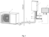
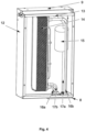
- The solution is illustrated in the picture, where the individual figures show:
fig. 1 - general scheme of the module installation,fig. 2 - cross-section of the pipeline with refrigeration pipes in a casing pipe,fig. 3 - axonometric view of the module, andfig. 4 - general view of the module without the cover. - The heat exchanger (14) module (1) has an exchanger - condenser (14), heating pipe connection (11a) of heating medium supply and heating medium inner supply pipe (17a), heating pipe connection (11b) of heating medium return and heating medium inner return pipe (17b), gas inner refrigeration pipe (16a), liquid inner refrigeration pipe (16b), heating medium system breather (13), universal wall/ceiling mount (9), and sealed housing (12) with cover (10).
- The module (1) is made of galvanized steel sheet, has seals in the form of silicone gaskets, and the sheet joints are made of rivets and tight rivets. The dimensions of the module (1) are width: 375 mm, height: 586 mm, depth: 165 mm. The pipe passages are sealed with glands at the bottom of the module (1). The connections of the inner refrigeration pipes (16a, 16b) to the refrigeration pipes (6a, 6b) of the refrigeration pipeline are encased in the casing pipe (7). The casing pipe (7) is at the same time a ventilation pipe connecting the ventilation system of the interior of the housing (12) of the module (1) with the outdoor unit (2). The module (1) contains a gas separator (15) coupled to a heat exchanger (14) on the side of the heating medium inner supply pipe (17a).
- In the method of installing a heat exchanger module (1) with a housing (12) is hung on the interior wall of the room and is connected to the outdoor unit (2) by refrigeration pipes (6a, 6b), which are placed in the casing pipe (7) connected to the module (1) by a sealed connection (8). The ventilation system of the interior of the housing (12) of the module (1) is connected to the casing pipe (7). The module (1) is also connected to heating medium pipes: heating medium supply pipe (5a) and heating medium return pipe (5b) with the indoor plumbing module (4) and through it with the heat receiver (3).
Claims (5)
- A heat exchanger module mounted inside the room, separating the heating/cooling system into an outdoor part and an indoor part, having an exchanger (condenser), heating medium input, heating medium output, liquid refrigeration pipe, gas refrigeration pipe, breather, refrigeration system connection, characterized in that a module (1) has a sealed housing (12) with a cover (10) and a sealed connection (8) of the casing pipe (7) of the internal refrigeration pipe connections (16a, 16b).
- The module according to the claim 1, characterized in that the casing pipe (7) is at the same time a ventilation pipe connecting the ventilation system of the interior of the housing (12) of the module (1) with the outdoor unit (2).
- The module according to the claim 1, characterized in that contains a gas separator (15) coupled to a heat exchanger (14) on the side of the heating medium inner supply pipe (17a).
- A method of installing the heat exchanger module, which involves mounting the module inside the room, characterized in that the module (1) with a housing (12) is connected to the outdoor unit (2) by refrigeration pipes (6a, 6b), which are placed in the casing pipe (7) connected to the module (1) by a sealed connection (8).
- The method according to the claim 4, characterized in that the ventilation system of the interior of the housing (12) of the module (1) is connected to the casing pipe (7).
Priority Applications (1)
| Application Number | Priority Date | Filing Date | Title |
|---|---|---|---|
| EP23185683.2A EP4491963A1 (en) | 2023-07-14 | 2023-07-14 | A heat exchanger module mounted inside the room and method of installing a heat exchanger module |
Applications Claiming Priority (1)
| Application Number | Priority Date | Filing Date | Title |
|---|---|---|---|
| EP23185683.2A EP4491963A1 (en) | 2023-07-14 | 2023-07-14 | A heat exchanger module mounted inside the room and method of installing a heat exchanger module |
Publications (1)
| Publication Number | Publication Date |
|---|---|
| EP4491963A1 true EP4491963A1 (en) | 2025-01-15 |
Family
ID=87340782
Family Applications (1)
| Application Number | Title | Priority Date | Filing Date |
|---|---|---|---|
| EP23185683.2A Pending EP4491963A1 (en) | 2023-07-14 | 2023-07-14 | A heat exchanger module mounted inside the room and method of installing a heat exchanger module |
Country Status (1)
| Country | Link |
|---|---|
| EP (1) | EP4491963A1 (en) |
Citations (4)
| Publication number | Priority date | Publication date | Assignee | Title |
|---|---|---|---|---|
| JPH11153332A (en) * | 1997-11-25 | 1999-06-08 | Matsushita Seiko Co Ltd | Multifunctional air conditioning system |
| US20080135636A1 (en) * | 2005-06-30 | 2008-06-12 | Kunio Sakai | Heat-pump-type water heater |
| US20140283540A1 (en) * | 2013-03-22 | 2014-09-25 | Carrier Corporation | Heat pump water module with condensing coil in water storage tank |
| EP3358272B1 (en) * | 2015-09-30 | 2020-06-17 | Daikin Industries, Ltd. | Water heat exchanger accommodation unit |
-
2023
- 2023-07-14 EP EP23185683.2A patent/EP4491963A1/en active Pending
Patent Citations (4)
| Publication number | Priority date | Publication date | Assignee | Title |
|---|---|---|---|---|
| JPH11153332A (en) * | 1997-11-25 | 1999-06-08 | Matsushita Seiko Co Ltd | Multifunctional air conditioning system |
| US20080135636A1 (en) * | 2005-06-30 | 2008-06-12 | Kunio Sakai | Heat-pump-type water heater |
| US20140283540A1 (en) * | 2013-03-22 | 2014-09-25 | Carrier Corporation | Heat pump water module with condensing coil in water storage tank |
| EP3358272B1 (en) * | 2015-09-30 | 2020-06-17 | Daikin Industries, Ltd. | Water heat exchanger accommodation unit |
Similar Documents
| Publication | Publication Date | Title |
|---|---|---|
| CN114423999B (en) | Heat pumps and how to install them | |
| JP6614389B1 (en) | Refrigeration equipment indoor unit | |
| EP3760936A1 (en) | Air conditioning device | |
| US5584185A (en) | Engine powered energy providing assemblies | |
| FR3070755B1 (en) | SAFETY DEVICES FOR REFRIGERATION PLANTS AND HEAT PUMPS USING TOXIC OR FLAMMABLE REFRIGERANT FLUIDS | |
| WO2023232501A1 (en) | An assembly of a housing and a drawer for heating water in a building | |
| US20130160479A1 (en) | Sound-attenuating housing | |
| EP2470842B1 (en) | Heat transport and ventilation device, and heat transport and ventilation system | |
| EP3441684B1 (en) | Heat source unit | |
| CN112432258B (en) | Refrigerant cuts device and air conditioning system | |
| RU2505895C1 (en) | Sealed fire-resistant cable transit | |
| JP2016161203A (en) | Heat source unit of refrigerator | |
| EP4345386A1 (en) | Heat pump apparatus | |
| US11041661B2 (en) | Wall mounted, concealed, water-to-water, water source heat pump with domestic hot water heat exchanger and storage tank | |
| CN201215091Y (en) | Low noise compressor assembly | |
| CN210511912U (en) | Indoor unit of air conditioner | |
| CN219913249U (en) | Air duct machine | |
| EP4286765A1 (en) | An assembly of a housing and a drawer for heating water in a building | |
| JP7841055B1 (en) | Outdoor unit and heat pump system equipped therewith | |
| JP2003106570A (en) | Air conditioner | |
| CN220793276U (en) | Add vertical tuber pipe machine | |
| CN215410665U (en) | Waterproof direct-burried insulating tube | |
| EP4350230A1 (en) | An air duct for a heat pump system | |
| RU202703U1 (en) | Modular supply and exhaust ventilation unit | |
| CN120593317A (en) | Unit type air conditioning unit |
Legal Events
| Date | Code | Title | Description |
|---|---|---|---|
| PUAI | Public reference made under article 153(3) epc to a published international application that has entered the european phase |
Free format text: ORIGINAL CODE: 0009012 |
|
| STAA | Information on the status of an ep patent application or granted ep patent |
Free format text: STATUS: THE APPLICATION HAS BEEN PUBLISHED |
|
| AK | Designated contracting states |
Kind code of ref document: A1 Designated state(s): AL AT BE BG CH CY CZ DE DK EE ES FI FR GB GR HR HU IE IS IT LI LT LU LV MC ME MK MT NL NO PL PT RO RS SE SI SK SM TR |
|
| STAA | Information on the status of an ep patent application or granted ep patent |
Free format text: STATUS: REQUEST FOR EXAMINATION WAS MADE |
|
| 17P | Request for examination filed |
Effective date: 20251001 |
|
| STAA | Information on the status of an ep patent application or granted ep patent |
Free format text: STATUS: EXAMINATION IS IN PROGRESS |
|
| 17Q | First examination report despatched |
Effective date: 20260603 |