EP4491953A1 - Refrigeration cycle device - Google Patents
Refrigeration cycle device Download PDFInfo
- Publication number
- EP4491953A1 EP4491953A1 EP23781100.5A EP23781100A EP4491953A1 EP 4491953 A1 EP4491953 A1 EP 4491953A1 EP 23781100 A EP23781100 A EP 23781100A EP 4491953 A1 EP4491953 A1 EP 4491953A1
- Authority
- EP
- European Patent Office
- Prior art keywords
- pipe
- compressor
- supported
- soundproof box
- support member
- Prior art date
- Legal status (The legal status is an assumption and is not a legal conclusion. Google has not performed a legal analysis and makes no representation as to the accuracy of the status listed.)
- Pending
Links
Images



Classifications
-
- F—MECHANICAL ENGINEERING; LIGHTING; HEATING; WEAPONS; BLASTING
- F04—POSITIVE - DISPLACEMENT MACHINES FOR LIQUIDS; PUMPS FOR LIQUIDS OR ELASTIC FLUIDS
- F04B—POSITIVE-DISPLACEMENT MACHINES FOR LIQUIDS; PUMPS
- F04B39/00—Component parts, details, or accessories, of pumps or pumping systems specially adapted for elastic fluids, not otherwise provided for in, or of interest apart from, groups F04B25/00 - F04B37/00
- F04B39/0027—Pulsation and noise damping means
- F04B39/0044—Pulsation and noise damping means with vibration damping supports
-
- F—MECHANICAL ENGINEERING; LIGHTING; HEATING; WEAPONS; BLASTING
- F04—POSITIVE - DISPLACEMENT MACHINES FOR LIQUIDS; PUMPS FOR LIQUIDS OR ELASTIC FLUIDS
- F04B—POSITIVE-DISPLACEMENT MACHINES FOR LIQUIDS; PUMPS
- F04B39/00—Component parts, details, or accessories, of pumps or pumping systems specially adapted for elastic fluids, not otherwise provided for in, or of interest apart from, groups F04B25/00 - F04B37/00
-
- F—MECHANICAL ENGINEERING; LIGHTING; HEATING; WEAPONS; BLASTING
- F04—POSITIVE - DISPLACEMENT MACHINES FOR LIQUIDS; PUMPS FOR LIQUIDS OR ELASTIC FLUIDS
- F04B—POSITIVE-DISPLACEMENT MACHINES FOR LIQUIDS; PUMPS
- F04B39/00—Component parts, details, or accessories, of pumps or pumping systems specially adapted for elastic fluids, not otherwise provided for in, or of interest apart from, groups F04B25/00 - F04B37/00
- F04B39/0027—Pulsation and noise damping means
- F04B39/0033—Pulsation and noise damping means with encapsulations
-
- F—MECHANICAL ENGINEERING; LIGHTING; HEATING; WEAPONS; BLASTING
- F16—ENGINEERING ELEMENTS AND UNITS; GENERAL MEASURES FOR PRODUCING AND MAINTAINING EFFECTIVE FUNCTIONING OF MACHINES OR INSTALLATIONS; THERMAL INSULATION IN GENERAL
- F16F—SPRINGS; SHOCK-ABSORBERS; MEANS FOR DAMPING VIBRATION
- F16F15/00—Suppression of vibrations in systems; Means or arrangements for avoiding or reducing out-of-balance forces, e.g. due to motion
- F16F15/02—Suppression of vibrations of non-rotating, e.g. reciprocating systems; Suppression of vibrations of rotating systems by use of members not moving with the rotating systems
- F16F15/04—Suppression of vibrations of non-rotating, e.g. reciprocating systems; Suppression of vibrations of rotating systems by use of members not moving with the rotating systems using elastic means
- F16F15/08—Suppression of vibrations of non-rotating, e.g. reciprocating systems; Suppression of vibrations of rotating systems by use of members not moving with the rotating systems using elastic means with rubber springs ; with springs made of rubber and metal
-
- F—MECHANICAL ENGINEERING; LIGHTING; HEATING; WEAPONS; BLASTING
- F24—HEATING; RANGES; VENTILATING
- F24F—AIR-CONDITIONING; AIR-HUMIDIFICATION; VENTILATION; USE OF AIR CURRENTS FOR SCREENING
- F24F1/00—Room units for air-conditioning, e.g. separate or self-contained units or units receiving primary air from a central station
- F24F1/06—Separate outdoor units, e.g. outdoor unit to be linked to a separate room comprising a compressor and a heat exchanger
- F24F1/08—Compressors specially adapted for separate outdoor units
- F24F1/12—Vibration or noise prevention thereof
-
- F—MECHANICAL ENGINEERING; LIGHTING; HEATING; WEAPONS; BLASTING
- F24—HEATING; RANGES; VENTILATING
- F24F—AIR-CONDITIONING; AIR-HUMIDIFICATION; VENTILATION; USE OF AIR CURRENTS FOR SCREENING
- F24F13/00—Details common to, or for air-conditioning, air-humidification, ventilation or use of air currents for screening
- F24F13/24—Means for preventing or suppressing noise
-
- F—MECHANICAL ENGINEERING; LIGHTING; HEATING; WEAPONS; BLASTING
- F25—REFRIGERATION OR COOLING; COMBINED HEATING AND REFRIGERATION SYSTEMS; HEAT PUMP SYSTEMS; MANUFACTURE OR STORAGE OF ICE; LIQUEFACTION SOLIDIFICATION OF GASES
- F25B—REFRIGERATION MACHINES, PLANTS OR SYSTEMS; COMBINED HEATING AND REFRIGERATION SYSTEMS; HEAT PUMP SYSTEMS
- F25B31/00—Compressor arrangements
-
- F—MECHANICAL ENGINEERING; LIGHTING; HEATING; WEAPONS; BLASTING
- F25—REFRIGERATION OR COOLING; COMBINED HEATING AND REFRIGERATION SYSTEMS; HEAT PUMP SYSTEMS; MANUFACTURE OR STORAGE OF ICE; LIQUEFACTION SOLIDIFICATION OF GASES
- F25B—REFRIGERATION MACHINES, PLANTS OR SYSTEMS; COMBINED HEATING AND REFRIGERATION SYSTEMS; HEAT PUMP SYSTEMS
- F25B2500/00—Problems to be solved
- F25B2500/12—Sound
-
- F—MECHANICAL ENGINEERING; LIGHTING; HEATING; WEAPONS; BLASTING
- F25—REFRIGERATION OR COOLING; COMBINED HEATING AND REFRIGERATION SYSTEMS; HEAT PUMP SYSTEMS; MANUFACTURE OR STORAGE OF ICE; LIQUEFACTION SOLIDIFICATION OF GASES
- F25B—REFRIGERATION MACHINES, PLANTS OR SYSTEMS; COMBINED HEATING AND REFRIGERATION SYSTEMS; HEAT PUMP SYSTEMS
- F25B2500/00—Problems to be solved
- F25B2500/13—Vibrations
Definitions
- the present disclosure relates to a refrigeration cycle apparatus.
- Patent Document 1 discloses a heat pump air conditioner.
- a compressor is mounted on a support member via a first vibration isolating member, the support member is placed in a machine body via a second vibration isolating member, and the compressor is hermetically covered with a soundproof box.
- Patent Document 1 Japanese Unexamined Patent Publication No. 2005-241197
- the soundproof box is placed on the support member supporting the compressor.
- the vibration of the compressor is disadvantageously transmitted to the soundproof box via the support member, and the soundproof box vibrates, generating vibration sound.
- An object of the present disclosure is to keep the vibration of a compressor from being transmitted to a soundproof box.
- a first aspect of the present disclosure is directed to a refrigeration cycle apparatus including a compressor (30) and a refrigerant circuit (2) to which the compressor (30) is connected.
- the refrigeration cycle apparatus includes: a first vibration isolating member (41) configured to support the compressor (30); a first support member (51) configured to support the first vibration isolating member (41), a second vibration isolating member (42) configured to support the first support member (51), a second support member (52) configured to support the second vibration isolating member (42); and a soundproof box (60) configured to cover the compressor (30).
- the soundproof box (60) is supported by the second support member (52).
- the compressor (30) is covered with the soundproof box (60), keeping radiated sound and vibration sound caused by the compressor (30) from leaking outside.
- the compressor (30) is supported by a two-layer antivibration structure made by stacking the first vibration isolating member (41) and the second vibration isolating member (42), and the soundproof box (60) is supported by the second support member (52) to which the vibration of the compressor (30) is less transmitted. This can keep the soundproof box (60) from vibrating.
- a second aspect of the present disclosure is an embodiment of the refrigeration cycle apparatus of the first aspect.
- the refrigeration cycle apparatus further includes: a second elastic member (65) configured to support the soundproof box (60), the soundproof box (60) is supported by the second elastic member (65), and the second elastic member (65) is supported by the second support member (52).
- the second elastic member (65) reduces the vibration transmitted from the compressor (30) to the second support member (52), reducing the transmission of the vibration to the soundproof box (60).
- a third aspect of the present disclosure is an embodiment of the refrigeration cycle apparatus of the first or second aspect.
- the refrigeration cycle apparatus further includes: a rigid member (35) provided on a pipe (26) connected to the compressor (30), and the rigid member (35) is supported by the first support member (51) or the second support member (52).
- the rigid member (35) reduces the vibration transmitted from the compressor (30) to the pipe (26), reducing the vibration sound generated by the vibration of the pipe (26).
- a fourth aspect of the present disclosure is an embodiment of the refrigeration cycle apparatus of the third aspect.
- the refrigeration cycle apparatus further includes a first elastic member (36) configured to support the rigid member (35), and the first elastic member (36) is supported by the second support member (52).
- the first elastic member (36) reduces, via the rigid member (35), the vibration transmitted from the compressor (30) to the pipe (26), reducing the transmission of the vibration to the second support member (52).
- a fifth aspect of the present disclosure is an embodiment of the refrigeration cycle apparatus of any one of the first to fourth aspects.
- the soundproof box (60) is provided with a pipe hole (63) through which a pipe (26) of the compressor (30) passes, and the refrigeration cycle apparatus further includes a first lid member (61) configured to be movable along a surface of the soundproof box (60) to close a gap between the pipe (26) and the pipe hole (63).
- the first lid member (61) can keep the radiated sound and the vibration sound caused by the compressor (30) from leaking from the pipe hole (63) of the soundproof box (60). Even when the pipe (26) vibrates in the pipe hole (63), the first lid member (61) moves along the surface of the soundproof box (60), keeping the gap closed.
- a sixth aspect of the present disclosure is an embodiment of the refrigeration cycle apparatus of any one of the first to fourth aspects.
- the soundproof box (60) is provided with a pipe hole (63) through which a pipe (26) of the compressor (30) passes, and the refrigeration cycle apparatus further includes a second lid member (62) configured to be fitted into the pipe hole (63) to close a gap between the pipe (26) and the pipe hole (63).
- the second lid member (62) can keep the pipe (26) and the soundproof box (60) from making contact with each other, and can also keep the radiated sound and the vibration sound caused by the compressor (30) from leaking out of the pipe hole (63) of the soundproof box (60).
- a seventh aspect of the present disclosure is an embodiment of the refrigeration cycle apparatus of any one of the first to sixth aspects.
- a component (5) of the refrigerant circuit (2) is disposed inside the soundproof box (60), and the component (5) includes an accumulator (25).
- the component (5) of the refrigerant circuit (2) is disposed inside the soundproof box (60), keeping the sound of the refrigerant flowing through the refrigerant circuit (2) from leaking outside. Further, the overall weight of the structure supported by the first vibration isolating member (41) and the second vibration isolating member (42) is increased, improving the effect of damping the vibration.
- An eighth aspect of the present disclosure is an embodiment of the refrigeration cycle apparatus of any one of the first to seventh aspects.
- a component (5) of the refrigerant circuit (2) is connected to a pipe (26) of the compressor (30), and the pipe (26) is disposed inside the soundproof box (60).
- the pipe (26) of the compressor (30) is disposed inside the soundproof box (60).
- the vibration sound can be kept from leaking outside.
- a ninth aspect of the present disclosure is an embodiment of the refrigeration cycle apparatus of any one of the first to eighth aspects.
- the soundproof box (60) is provided with a sound absorber (66).
- the sound absorber (66) provided for the soundproof box (60) can absorb the radiated sound and the vibration sound caused by the compressor (30), keeping the sounds from leaking outside.
- a refrigeration cycle apparatus (1) includes an air conditioner unit (10) and an outdoor unit (20).
- the outdoor unit (20) includes a refrigerant circuit (2).
- the refrigerant circuit (2) is filled with, for example, a flammable natural refrigerant.
- the refrigerant circuit (2) circulates the refrigerant to perform a refrigeration cycle.
- the air conditioner unit (10) includes an air conditioner (11).
- the air conditioner (11) is connected to a fluid circuit (12).
- a temperature adjustment fluid flows through the fluid circuit (12).
- the temperature adjustment fluid is, for example, water.
- the air conditioner (11) is installed in an indoor space to be air-conditioned.
- the fluid circuit (12) includes the air conditioner (11), a fluid pump (16), and a water heat exchanger (15) connected by a fluid pipe (17).
- the fluid pump (16) circulates water in the fluid circuit (12).
- the outdoor unit (20) includes the water heat exchanger (15), an outdoor heat exchanger (21), an outdoor fan (22), an outdoor expansion valve (23), a four-way switching valve (24), an accumulator (25), and a compressor (30).
- the outdoor heat exchanger (21), the outdoor expansion valve (23), the four-way switching valve (24), and the compressor (30) are connected by a pipe (26).
- the refrigerant flows through the pipe (26).
- the outdoor heat exchanger (21) is, for example, a cross-fin type fin-and-tube heat exchanger. In the outdoor heat exchanger (21), heat exchange occurs between the refrigerant flowing through the outdoor heat exchanger (21) and air blown by the outdoor fan (22).
- the outdoor expansion valve (23) is, for example, an electronic expansion valve.
- the compressor (30) is, for example, a rotary compressor such as a scroll compressor.
- the four-way switching valve (24) is connected to the pipe (26) on the discharge side of the compressor (30).
- the accumulator (25) is connected to the pipe (26) on the suction side of the compressor (30).
- the pipe (26) of the refrigerant circuit (2) is connected to the water heat exchanger (15).
- the water heat exchanger (15) causes heat exchange between the refrigerant flowing through the pipe (26) and water flowing through the fluid pipe (17).
- the four-way switching valve (24) has a first port (P1), a second port (P2), a third port (P3), and a fourth port (P4).
- the four-way switching valve (24) is in a state (indicated by the solid line in FIG. 1 ) where the first port (P1) and the third port (P3) are in communication with each other, and the second port (P2) and the fourth port (P4) are in communication with each other.
- the air conditioner (11) is a heat exchanger that functions as a radiator of the temperature adjustment fluid circulating in the fluid circuit (12).
- the air conditioner (11) is an example of a target for temperature adjustment.
- the air conditioner (11) is specifically a device such as a radiator or a floor cooling/heating panel.
- the air conditioner (11) is provided near a wall or the like in the room.
- the air conditioner (11) is provided under the floor or the like of the room.
- the refrigeration cycle apparatus (1) is described as a device including the refrigerant circuit (2) and the fluid circuit (12), but the refrigeration cycle apparatus (1) is not limited to this configuration.
- the refrigeration cycle apparatus (1) may be an air conditioner including a single refrigerant circuit (2).
- the outdoor unit (20) includes a body casing (27).
- the body casing (27) is formed in a box shape.
- a partitioning member (28) is disposed upright in the body casing (27). The partitioning member (28) partitions the body casing (27) into a machine chamber (S 1) and a fan chamber (S2).
- the machine chamber (S1) is a space in the body casing (27) on the right side of the partitioning member (28) in FIG. 2 .
- the compressor (30), the water heat exchanger (15), the four-way switching valve (24), the accumulator (25), and the pipe (26) are placed in the machine chamber (S1).
- the fan chamber (S2) is a space in the body casing (27) on the left side of the partitioning member (28) in FIG. 2 .
- the outdoor fan (22) and the outdoor heat exchanger (21) are placed in the fan chamber (S2).
- the compressor (30) includes a support leg (31).
- the support leg (31) is supported by a plurality of first vibration isolating members (41).
- the first vibration isolating members (41) are made of, for example, rubber or urethane.
- the first vibration isolating members (41) are supported by a first support member (51).
- the first support member (51) is supported by a plurality of second vibration isolating members (42).
- the second vibration isolating members (42) are made of, for example, rubber or urethane.
- the first vibration isolating members (41) and the second vibration isolating members (42) may be made of the same material or different materials, and may have the same spring constant or different spring constants.
- the second vibration isolating members (42) are supported by a second support member (52).
- the second support member (52) is a bottom plate of the body casing (27).
- a soundproof box (60) is formed in the shape of a box that opens downward.
- a pipe hole (63) is formed in an upper surface of the soundproof box (60).
- the pipe (26) of the compressor (30) is drawn out of the soundproof box (60) through the pipe hole (63).
- the soundproof box (60) is supported by the second support member (52).
- the compressor (30) is covered with the soundproof box (60), keeping radiated sound and vibration sound caused by the compressor (30) from leaking outside.
- the compressor (30) is supported by a two-layer antivibration structure made by stacking the first vibration isolating members (41) and the second vibration isolating members (42), and the soundproof box (60) is supported by the second support member (52) to which the vibration of the compressor (30) is less transmitted. This can keep the soundproof box (60) from vibrating.
- a second support member (52) different from the bottom plate (29) may be placed on the bottom plate (29).
- the support leg (31) of the compressor (30) is supported by the plurality of first vibration isolating members (41).
- the first vibration isolating members (41) are supported by the first support member (51).
- the first support member (51) is supported by the plurality of second vibration isolating members (42).
- the second vibration isolating members (42) are supported by the second support member (52).
- the second support member (52) is supported by the bottom plate (29).
- the soundproof box (60) is formed in the shape of a box that opens downward.
- the pipe hole (63) is formed in the upper surface of the soundproof box (60).
- the pipe (26) of the compressor (30) is drawn out of the soundproof box (60) through the pipe hole (63).
- the soundproof box (60) is supported by the second support member (52).
- the compressor (30) can be supported by the flat surface of the first support member (51) even when the bottom plate (29) has an uneven top surface.
- the soundproof box (60) may be supported by a second elastic member (65).
- the support leg (31) of the compressor (30) is supported by the plurality of first vibration isolating members (41).
- the first vibration isolating members (41) are supported by the first support member (51).
- the first support member (51) is supported by the plurality of second vibration isolating members (42).
- the second vibration isolating members (42) are supported by the second support member (52).
- the soundproof box (60) is supported by the second elastic member (65).
- the second elastic member (65) is made of, for example, rubber or urethane.
- the second elastic member (65) is supported by the second support member (52).
- the pipe (26) of the compressor (30) is drawn out of the soundproof box (60) through the pipe hole (63).
- the second elastic member (65) reduces the vibration transmitted from the compressor (30) to the second support member (52), keeping the vibration from being transmitted to the soundproof box (60).
- a rigid member (35) may be provided on the pipe (26) of the compressor (30).
- the support leg (31) of the compressor (30) is supported by the plurality of first vibration isolating members (41).
- the first vibration isolating members (41) are supported by the first support member (51).
- the first support member (51) is supported by the plurality of second vibration isolating members (42).
- the second vibration isolating members (42) are supported by the second support member (52).
- the pipe (26) is connected to the compressor (30).
- the pipe (26) is formed of, for example, a copper pipe.
- the pipe (26) is provided with the rigid member (35).
- the rigid member (35) is made of a material that is more rigid than the pipe (26).
- the rigid member (35) is made of, for example, a metal material having a specific gravity of 2.5 or more.
- the rigid member (35) is supported by the first support member (51).
- the soundproof box (60) is supported by the second elastic member (65).
- the second elastic member (65) is made of rubber or urethan.
- the second elastic member (65) is supported by the second support member (52).
- the pipe (26) of the compressor (30) is drawn out of the soundproof box (60) through the pipe hole (63).
- the rigid member (35) reduces the vibration transmitted from the compressor (30) to the pipe (26), reducing the vibration sound generated by the vibration of the pipe (26).
- the rigid member (35) may be supported by a first elastic member (36).
- the support leg (31) of the compressor (30) is supported by the plurality of first vibration isolating members (41).
- the first vibration isolating members (41) are supported by the first support member (51).
- the first support member (51) is supported by the plurality of second vibration isolating members (42).
- the second vibration isolating members (42) are supported by the second support member (52).
- the rigid member (35) is provided on the pipe (26) of the compressor (30).
- the rigid member (35) is supported by the first elastic member (36).
- the first elastic member (36) is supported by the first support member (51).
- the soundproof box (60) is supported by the second elastic member (65).
- the second elastic member (65) is made of rubber or urethan.
- the second elastic member (65) is supported by the second support member (52).
- the pipe (26) of the compressor (30) is drawn out of the soundproof box (60) through the pipe hole (63).
- the first elastic member (36) reduces, via the rigid member (35), the vibration transmitted from the compressor (30) to the pipe (26), reducing the transmission of the vibration to the second support member (52).
- the second elastic member (65) reduces the vibration transmitted from the compressor (30) to the second support member (52), reducing the transmission of the vibration to the soundproof box (60).
- the pipe (26) passing through the pipe hole (63) is less likely to make contact with the soundproof box (60).
- the diameter of the pipe hole (63) can be reduced. This can reduce sound leakage from the pipe hole (63) of the soundproof box (60).
- a gap between the pipe (26) of the compressor (30) and the pipe hole (63) of the soundproof box (60) may be closed by a first lid member (61).
- the support leg (31) of the compressor (30) is supported by the plurality of first vibration isolating members (41).
- the first vibration isolating members (41) are supported by the first support member (51).
- the first support member (51) is supported by the plurality of second vibration isolating members (42).
- the second vibration isolating members (42) are supported by the second support member (52).
- the rigid member (35) is provided on the pipe (26) of the compressor (30).
- the rigid member (35) is supported by the first elastic member (36).
- the first elastic member (36) is supported by the first support member (51).
- the soundproof box (60) is supported by the second elastic member (65).
- the second elastic member (65) is supported by the second support member (52).
- the pipe (26) of the compressor (30) is drawn out of the soundproof box (60) through the pipe hole (63).
- the first lid member (61) is attached to the pipe (26).
- the first lid member (61) is disposed on the upper surface of the soundproof box (60).
- the first lid member (61) closes the gap between the pipe (26) and the pipe hole (63).
- the first lid member (61) is movable along the upper surface of the soundproof box (60) as the pipe (26) vibrates.
- the first lid member (61) can keep the radiated sound and the vibration sound caused by the compressor (30) from leaking from the pipe hole (63) of the soundproof box (60). Even when the pipe (26) vibrates in the pipe hole (63), the first lid member (61) moves along the surface of the soundproof box (60), keeping the gap closed.
- a gap between the pipe (26) of the compressor (30) and the pipe hole (63) of the soundproof box (60) may be closed by a second lid member (62).
- the support leg (31) of the compressor (30) is supported by the plurality of first vibration isolating members (41).
- the first vibration isolating members (41) are supported by the first support member (51).
- the first support member (51) is supported by the plurality of second vibration isolating members (42).
- the second vibration isolating members (42) are supported by the second support member (52).
- the rigid member (35) is provided on the pipe (26) of the compressor (30).
- the rigid member (35) is supported by the first elastic member (36).
- the first elastic member (36) is supported by the first support member (51).
- the soundproof box (60) is supported by the second elastic member (65).
- the second elastic member (65) is supported by the second support member (52).
- the pipe (26) of the compressor (30) is drawn out of the soundproof box (60) through the pipe hole (63).
- the second lid member (62) is attached to the pipe (26).
- the second lid member (62) is fitted into the pipe hole (63).
- the second lid member (62) closes the gap between the pipe (26) and the pipe hole (63).
- the second lid member (62) is formed of an elastically deformable member.
- the second lid member (62) is made of, for example, rubber or urethane. The second lid member (62) elastically deforms as the pipe (26) vibrates.
- the second lid member (62) can keep the pipe (26) and the soundproof box (60) from making contact with each other, and can also keep the radiated sound and the vibration sound caused by the compressor (30) from leaking out of the pipe hole (63) of the soundproof box (60).
- the soundproof box (60) may be provided with a sound absorber (66).
- the support leg (31) of the compressor (30) is supported by the plurality of first vibration isolating members (41).
- the first vibration isolating members (41) are supported by the first support member (51).
- the first support member (51) is supported by the plurality of second vibration isolating members (42).
- the second vibration isolating members (42) are supported by the second support member (52).
- the rigid member (35) is provided on the pipe (26) of the compressor (30).
- the rigid member (35) is supported by the first elastic member (36).
- the first elastic member (36) is supported by the first support member (51).
- the soundproof box (60) is supported by the second elastic member (65).
- the second elastic member (65) is supported by the second support member (52).
- the pipe (26) of the compressor (30) is drawn out of the soundproof box (60) through the pipe hole (63).
- the first lid member (61) is attached to the pipe (26).
- the first lid member (61) is disposed on the upper surface of the soundproof box (60).
- the first lid member (61) closes the gap between the pipe (26) and the pipe hole (63).
- the first lid member (61) is movable along the upper surface of the soundproof box (60) as the pipe (26) vibrates.
- the sound absorber (66) is provided on an inner surface of the soundproof box (60).
- the sound absorber (66) may be provided on an outer surface of the soundproof box (60).
- the sound absorber (66) provided for the soundproof box (60) can absorb the radiated sound and the vibration sound caused by the compressor (30), keeping the sounds from leaking outside.
- the soundproof box (60) provided with the sound absorber (66) is applicable to the other embodiments and variations in the same manner.
- components (5) of the refrigerant circuit (2) may be disposed in the soundproof box (60).
- the support leg (31) of the compressor (30) is supported by the plurality of first vibration isolating members (41).
- the first vibration isolating members (41) are supported by the first support member (51).
- the first support member (51) is supported by the plurality of second vibration isolating members (42).
- the second vibration isolating members (42) are supported by the second support member (52).
- the rigid member (35) is provided on the pipe (26) of the compressor (30).
- the rigid member (35) is supported by the first elastic member (36).
- the first elastic member (36) is supported by the first support member (51).
- the components (5) of the refrigerant circuit (2) include the water heat exchanger (15) and the accumulator (25).
- the water heat exchanger (15) and the accumulator (25) are supported by the second support member (52).
- the accumulator (25) is connected to the compressor (30) by the pipe (26).
- the components (5) of the refrigerant circuit (2) disposed in the soundproof box (60) may further include, for example, other components such as the four-way switching valve (24), and an electromagnetic valve, an electric valve, an economizer, and a muffler which are not shown, in addition to the water heat exchanger (15) and the accumulator (25).
- other components such as the four-way switching valve (24), and an electromagnetic valve, an electric valve, an economizer, and a muffler which are not shown, in addition to the water heat exchanger (15) and the accumulator (25).
- the pipe (26) connecting the compressor (30) and the accumulator (25) is covered with the soundproof box (60).
- the soundproof box (60) is supported by the second elastic member (65).
- the second elastic member (65) is supported by the second support member (52).
- the pipe (26) of the compressor (30) is drawn out of the soundproof box (60) through the pipe hole (63).
- the whole part of the pipe (26) connecting the compressor (30) and the accumulator (25) does not need to be disposed inside the soundproof box (60), and part of the pipe (26) may be drawn out of the soundproof box (60).
- the first lid member (61) is attached to the pipe (26).
- the first lid member (61) is disposed on the upper surface of the soundproof box (60).
- the first lid member (61) closes the gap between the pipe (26) and the pipe hole (63).
- the first lid member (61) is movable along the upper surface of the soundproof box (60) as the pipe (26) vibrates.
- the components (5) of the refrigerant circuit (2) are disposed inside the soundproof box (60), keeping the sound of the refrigerant flowing through the refrigerant circuit (2) from leaking outside.
- the pipe (26) of the compressor (30) is disposed inside the soundproof box (60).
- the vibration sound can be kept from leaking outside.
- the components (5) of the refrigerant circuit (2) may be supported by the first support member (51).
- the support leg (31) of the compressor (30) is supported by the plurality of first vibration isolating members (41).
- the first vibration isolating members (41) are supported by the first support member (51).
- the first support member (51) is supported by the plurality of second vibration isolating members (42).
- the second vibration isolating members (42) are supported by the second support member (52).
- the rigid member (35) is provided on the pipe (26) of the compressor (30).
- the rigid member (35) is supported by the first elastic member (36).
- the first elastic member (36) is supported by the first support member (51).
- the components (5) of the refrigerant circuit (2) include the water heat exchanger (15) and the accumulator (25).
- the water heat exchanger (15) and the accumulator (25) are supported by the first support member (51).
- the accumulator (25) is connected to the compressor (30) by the pipe (26).
- the pipe (26) connecting the compressor (30) and the accumulator (25) is covered with the soundproof box (60).
- the soundproof box (60) is supported by the second elastic member (65).
- the second elastic member (65) is supported by the second support member (52).
- the pipe (26) of the compressor (30) is drawn out of the soundproof box (60) through the pipe hole (63).
- the first lid member (61) is attached to the pipe (26).
- the first lid member (61) is disposed on the upper surface of the soundproof box (60).
- the first lid member (61) closes the gap between the pipe (26) and the pipe hole (63).
- the first lid member (61) is movable along the upper surface of the soundproof box (60) as the pipe (26) vibrates.
- the components (5) of the refrigerant circuit (2) are disposed inside the soundproof box (60), keeping the sound of the refrigerant flowing through the refrigerant circuit (2) from leaking outside. Further, the overall weight of the structure supported by the first vibration isolating members (41) and the second vibration isolating members (42) is increased, improving the effect of damping the vibration.
- the pipe (26) of the compressor (30) is disposed inside the soundproof box (60).
- the vibration sound can be kept from leaking outside.
- the rigid member (35) may be supported by the second support member (52).
- the support leg (31) of the compressor (30) is supported by the plurality of first vibration isolating members (41).
- the first vibration isolating members (41) are supported by the first support member (51).
- the first support member (51) is supported by the plurality of second vibration isolating members (42).
- the second vibration isolating members (42) are supported by the second support member (52).
- the rigid member (35) is provided on the pipe (26) of the compressor (30).
- the rigid member (35) is supported by the first elastic member (36).
- the first elastic member (36) is supported by the second support member (52).
- the soundproof box (60) is formed in the shape of a box that opens downward.
- the pipe hole (63) is formed in the upper surface of the soundproof box (60).
- the pipe (26) of the compressor (30) is drawn out of the soundproof box (60) through the pipe hole (63).
- the soundproof box (60) is supported by the second support member (52).
- the first lid member (61) is attached to the pipe (26).
- the first lid member (61) is disposed on the upper surface of the soundproof box (60).
- the first lid member (61) closes the gap between the pipe (26) and the pipe hole (63).
- the first lid member (61) is movable along the upper surface of the soundproof box (60) as the pipe (26) vibrates.
- the compressor (30) is supported by a two-layer antivibration structure made by stacking the first vibration isolating members (41) and the second vibration isolating members (42), reducing the vibration transmitted from the compressor (30) to the second support member (52) and the vibration transmitted from the compressor (30) to the pipe (26). This can reduce the vibration sound generated by the vibration of the second support member (52) and the pipe (26).
- the rigid member (35) reduces the vibration transmitted from the compressor (30) to the pipe (26), keeping the vibration from being transmitted to the second support member (52).
- the compressor (30) is covered with the soundproof box (60), keeping the radiated sound and the vibration sound caused by the compressor (30) from leaking outside.
- the soundproof box (60) may be supported by a second elastic member (65).
- the support leg (31) of the compressor (30) is supported by the plurality of first vibration isolating members (41).
- the first vibration isolating members (41) are supported by the first support member (51).
- the first support member (51) is supported by the plurality of second vibration isolating members (42).
- the second vibration isolating members (42) are supported by the second support member (52).
- the rigid member (35) is provided on the pipe (26) of the compressor (30).
- the rigid member (35) is supported by the first elastic member (36).
- the first elastic member (36) is supported by the second support member (52).
- the soundproof box (60) is supported by the second elastic member (65).
- the second elastic member (65) is made of, for example, rubber or urethane.
- the second elastic member (65) is supported by the second support member (52).
- the pipe (26) of the compressor (30) is drawn out of the soundproof box (60) through the pipe hole (63).
- the first lid member (61) is attached to the pipe (26).
- the first lid member (61) is disposed on the upper surface of the soundproof box (60).
- the first lid member (61) closes the gap between the pipe (26) and the pipe hole (63).
- the first lid member (61) is movable along the upper surface of the soundproof box (60) as the pipe (26) vibrates.
- the second elastic member (65) reduces the vibration transmitted from the compressor (30) to the second support member (52), keeping the vibration from being transmitted to the soundproof box (60).
- the pipe (26) passing through the pipe hole (63) is less likely to make contact with the soundproof box (60).
- the diameter of the pipe hole (63) can be reduced. This can reduce sound leakage from the pipe hole (63) of the soundproof box (60).
- components (5) of the refrigerant circuit (2) may be disposed in the soundproof box (60).
- the support leg (31) of the compressor (30) is supported by the plurality of first vibration isolating members (41).
- the first vibration isolating members (41) are supported by the first support member (51).
- the first support member (51) is supported by the plurality of second vibration isolating members (42).
- the second vibration isolating members (42) are supported by the second support member (52).
- the rigid member (35) is provided on the pipe (26) of the compressor (30).
- the rigid member (35) is supported by the first elastic member (36).
- the first elastic member (36) is supported by the second support member (52).
- the components (5) of the refrigerant circuit (2) include the water heat exchanger (15) and the accumulator (25).
- the water heat exchanger (15) and the accumulator (25) are supported by the second support member (52).
- the accumulator (25) is connected to the compressor (30) by the pipe (26).
- the pipe (26) connecting the compressor (30) and the accumulator (25) is covered with the soundproof box (60).
- the soundproof box (60) is supported by the second elastic member (65).
- the second elastic member (65) is supported by the second support member (52).
- the pipe (26) of the compressor (30) is drawn out of the soundproof box (60) through the pipe hole (63).
- the first lid member (61) is attached to the pipe (26).
- the first lid member (61) is disposed on the upper surface of the soundproof box (60).
- the first lid member (61) closes the gap between the pipe (26) and the pipe hole (63).
- the first lid member (61) is movable along the upper surface of the soundproof box (60) as the pipe (26) vibrates.
- the components (5) of the refrigerant circuit (2) are disposed inside the soundproof box (60), keeping the sound of the refrigerant flowing through the refrigerant circuit (2) from leaking outside.
- the pipe (26) of the compressor (30) is disposed inside the soundproof box (60).
- the vibration sound can be kept from leaking outside.
- the components (5) of the refrigerant circuit (2) may be supported by the first support member (51).
- the support leg (31) of the compressor (30) is supported by the plurality of first vibration isolating members (41).
- the first vibration isolating members (41) are supported by the first support member (51).
- the first support member (51) is supported by the plurality of second vibration isolating members (42).
- the second vibration isolating members (42) are supported by the second support member (52).
- the rigid member (35) is provided on the pipe (26) of the compressor (30).
- the rigid member (35) is supported by the first elastic member (36).
- the first elastic member (36) is supported by the second support member (52).
- the components (5) of the refrigerant circuit (2) include the water heat exchanger (15) and the accumulator (25).
- the water heat exchanger (15) and the accumulator (25) are supported by the first support member (51).
- the accumulator (25) is connected to the compressor (30) by the pipe (26).
- the pipe (26) connecting the compressor (30) and the accumulator (25) is covered with the soundproof box (60).
- the soundproof box (60) is supported by the second elastic member (65).
- the second elastic member (65) is supported by the second support member (52).
- the pipe (26) of the compressor (30) is drawn out of the soundproof box (60) through the pipe hole (63).
- the first lid member (61) is attached to the pipe (26).
- the first lid member (61) is disposed on the upper surface of the soundproof box (60).
- the first lid member (61) closes the gap between the pipe (26) and the pipe hole (63).
- the first lid member (61) is movable along the upper surface of the soundproof box (60) as the pipe (26) vibrates.
- the components (5) of the refrigerant circuit (2) are disposed inside the soundproof box (60), keeping the sound of the refrigerant flowing through the refrigerant circuit (3) from leaking outside. Further, the overall weight of the structure supported by the first vibration isolating members (41) and the second vibration isolating members (42) is increased, improving the effect of damping the vibration.
- the pipe (26) of the compressor (30) is disposed inside the soundproof box (60).
- the vibration sound can be kept from leaking outside.
- the pipe (26) of the compressor (30) passes through the pipe hole (63) formed in the soundproof box (60).
- the present invention is not limited to this configuration.
- a first pipe hole (71) may be formed in the upper surface of the soundproof box (60), and a first connection pipe (81) of the outdoor heat exchanger (21), which is an air heat exchanger, may pass through the first pipe hole (71).
- the first connection pipe (81) is a pipe (26) connected to an outlet of an evaporator during heating operation.
- a gap (75) may be provided between the lower edge of the soundproof box (60) and the second support member (52) serving as the bottom plate of the body casing (27), and a second connection pipe (82) of the outdoor heat exchanger (21) may pass through the gap (75).
- the second connection pipe (82) is a pipe (26) connected to an inlet of the evaporator during heating operation.
- the second connection pipe (82) may have any structure of a subcooling path inlet, a flow divider inlet, and a pipe downstream of the flow divider.
- a pipe hole (not shown) may be formed in a lower portion of a back wall surface of the soundproof box (60), and the second connection pipe (82) of the outdoor heat exchanger (21) may pass through the pipe hole.
- a gap (75) may be provided between the lower edge of the soundproof box (60) and the second support member (52) serving as the bottom plate of the main casing (27), and a bypass pipe (83) for bypassing hot gas may pass through the gap (75).
- a pipe hole (not shown) may be formed in a lower portion of a side wall surface of the soundproof box (60), and the bypass pipe (83) may pass through the pipe hole. This can avoid melting of snow or ice-up on the second support member (52) which is the bottom plate of the body casing (27).
- a water pipe hole (72) may be formed in a lower portion of the back wall surface of the soundproof box (60), and the fluid pipe (17) of the water heat exchanger (15) may pass through the water pipe hole (72).
- a wire hole (73) may be formed in a front wall surface of the soundproof box (60), and a wire (85) connected to various components contained in the soundproof box (60) may be drawn out of the soundproof box (60) through the wire hole (73).
- the wire hole (73) may be formed in the back wall surface of the soundproof box (60).
- the second pipe hole (74) may be formed in the back wall surface of the soundproof box (60) so that a gas release pipe (94) of the gas-liquid separator (90) passes through the second pipe hole (74).
- the gas-liquid separator (90) includes a separator body (91), a pressure relief valve (92), a gas release valve (93), and a gas release pipe (94).
- the gas-liquid separator (90) is disposed between the water heat exchanger (15) and the air conditioner (11) in the fluid circuit (12).
- the separator body (91) has a space into which water flows.
- the separator body (91) is, for example, a cylindrical container extending in the vertical direction.
- a fluid pipe (17) on the inlet side into which water having passed through the water heat exchanger (15) flows is connected to an upper portion of a side surface of the separator body (91).
- a fluid pipe (17) on the outlet side from which water flows toward the air conditioner (11) is connected to a lower portion of a side surface of the separator body (91).
- the pressure relief valve (92) operates to release water in the separator body (91) to the outside when the pressure in the separator body (91) reaches or exceeds a predetermined value. This regulates the pressure in the separator body (91).
- the gas release valve (93) discharges the gas flowing into the separator body (91) to the outside of the separator body (91).
- the gas release valve (93) includes, for example, a float-shaped valve body (not shown).
- the gas release valve (93) closes a discharge port (not shown) when the valve body is pushed up by water, and discharges gas from the discharge port when the gas flows into the separator body (91) to lower the liquid level and the valve body opens the discharge port.
- the gas flowing into the separator body (91) is a refrigerant which has leaked from the pipe (26) connected to the water heat exchanger (15) and has entered the fluid pipe (17) of the water heat exchanger (15).
- the gas-liquid separator (90) is provided to discharge the refrigerant that has entered the fluid pipe (17).
- the gas release pipe (94) is connected to the gas release valve (93).
- the gas release pipe (94) is, for example, a copper pipe, a resin pipe, or a hose.
- the gas release pipe (94) is drawn out of the soundproof box (60) through the second pipe hole (74) of the soundproof box (60).
- the rigid member (35) is provided at some midpoint of the pipe (26), but the present invention is not limited to this configuration.
- the rigid member (35) may be a manifold having a flow path hole, and the pipe (26) may be connected to the flow path hole of the rigid member (35).
- the rigid member (35) is made of a block-shaped metal material, but the present invention is not limited to this configuration.
- the accumulator (25) arranged away from the compressor (30) may be used as the rigid member (35).
- the pipe (26) on the discharge side of the compressor (30) may be fixed to a side surface of the accumulator (25) so that the accumulator (25) reduces the vibration transmitted from the compressor (30) to the pipe (26) on the discharge side.
- the present disclosure is useful for a refrigeration cycle apparatus.
Landscapes
- Engineering & Computer Science (AREA)
- General Engineering & Computer Science (AREA)
- Mechanical Engineering (AREA)
- Physics & Mathematics (AREA)
- Chemical & Material Sciences (AREA)
- Combustion & Propulsion (AREA)
- Thermal Sciences (AREA)
- Acoustics & Sound (AREA)
- Aviation & Aerospace Engineering (AREA)
- Compressor (AREA)
- Vibration Prevention Devices (AREA)
Abstract
Description
- The present disclosure relates to a refrigeration cycle apparatus.
-
Patent Document 1 discloses a heat pump air conditioner. In this heat pump air conditioner, a compressor is mounted on a support member via a first vibration isolating member, the support member is placed in a machine body via a second vibration isolating member, and the compressor is hermetically covered with a soundproof box. - Patent Document 1:
Japanese Unexamined Patent Publication No. 2005-241197 - According to the invention of
Patent Document 1, the soundproof box is placed on the support member supporting the compressor. Thus, the vibration of the compressor is disadvantageously transmitted to the soundproof box via the support member, and the soundproof box vibrates, generating vibration sound. - An object of the present disclosure is to keep the vibration of a compressor from being transmitted to a soundproof box.
- A first aspect of the present disclosure is directed to a refrigeration cycle apparatus including a compressor (30) and a refrigerant circuit (2) to which the compressor (30) is connected. The refrigeration cycle apparatus includes: a first vibration isolating member (41) configured to support the compressor (30); a first support member (51) configured to support the first vibration isolating member (41), a second vibration isolating member (42) configured to support the first support member (51), a second support member (52) configured to support the second vibration isolating member (42); and a soundproof box (60) configured to cover the compressor (30). The soundproof box (60) is supported by the second support member (52).
- In the first aspect, the compressor (30) is covered with the soundproof box (60), keeping radiated sound and vibration sound caused by the compressor (30) from leaking outside. The compressor (30) is supported by a two-layer antivibration structure made by stacking the first vibration isolating member (41) and the second vibration isolating member (42), and the soundproof box (60) is supported by the second support member (52) to which the vibration of the compressor (30) is less transmitted. This can keep the soundproof box (60) from vibrating.
- A second aspect of the present disclosure is an embodiment of the refrigeration cycle apparatus of the first aspect. In the second aspect, the refrigeration cycle apparatus further includes: a second elastic member (65) configured to support the soundproof box (60), the soundproof box (60) is supported by the second elastic member (65), and the second elastic member (65) is supported by the second support member (52).
- In the second aspect, the second elastic member (65) reduces the vibration transmitted from the compressor (30) to the second support member (52), reducing the transmission of the vibration to the soundproof box (60).
- A third aspect of the present disclosure is an embodiment of the refrigeration cycle apparatus of the first or second aspect. In the third aspect, the refrigeration cycle apparatus further includes: a rigid member (35) provided on a pipe (26) connected to the compressor (30), and the rigid member (35) is supported by the first support member (51) or the second support member (52).
- In the third aspect, the rigid member (35) reduces the vibration transmitted from the compressor (30) to the pipe (26), reducing the vibration sound generated by the vibration of the pipe (26).
- A fourth aspect of the present disclosure is an embodiment of the refrigeration cycle apparatus of the third aspect. In the fourth aspect, the refrigeration cycle apparatus further includes a first elastic member (36) configured to support the rigid member (35), and the first elastic member (36) is supported by the second support member (52).
- In the fourth aspect, the first elastic member (36) reduces, via the rigid member (35), the vibration transmitted from the compressor (30) to the pipe (26), reducing the transmission of the vibration to the second support member (52).
- A fifth aspect of the present disclosure is an embodiment of the refrigeration cycle apparatus of any one of the first to fourth aspects. In the fifth aspect, the soundproof box (60) is provided with a pipe hole (63) through which a pipe (26) of the compressor (30) passes, and the refrigeration cycle apparatus further includes a first lid member (61) configured to be movable along a surface of the soundproof box (60) to close a gap between the pipe (26) and the pipe hole (63).
- In the fifth aspect, the first lid member (61) can keep the radiated sound and the vibration sound caused by the compressor (30) from leaking from the pipe hole (63) of the soundproof box (60). Even when the pipe (26) vibrates in the pipe hole (63), the first lid member (61) moves along the surface of the soundproof box (60), keeping the gap closed.
- A sixth aspect of the present disclosure is an embodiment of the refrigeration cycle apparatus of any one of the first to fourth aspects. In the sixth aspect, the soundproof box (60) is provided with a pipe hole (63) through which a pipe (26) of the compressor (30) passes, and the refrigeration cycle apparatus further includes a second lid member (62) configured to be fitted into the pipe hole (63) to close a gap between the pipe (26) and the pipe hole (63).
- In the sixth aspect, the second lid member (62) can keep the pipe (26) and the soundproof box (60) from making contact with each other, and can also keep the radiated sound and the vibration sound caused by the compressor (30) from leaking out of the pipe hole (63) of the soundproof box (60).
- A seventh aspect of the present disclosure is an embodiment of the refrigeration cycle apparatus of any one of the first to sixth aspects. In the seventh aspect, a component (5) of the refrigerant circuit (2) is disposed inside the soundproof box (60), and the component (5) includes an accumulator (25).
- In the seventh aspect, the component (5) of the refrigerant circuit (2) is disposed inside the soundproof box (60), keeping the sound of the refrigerant flowing through the refrigerant circuit (2) from leaking outside. Further, the overall weight of the structure supported by the first vibration isolating member (41) and the second vibration isolating member (42) is increased, improving the effect of damping the vibration.
- An eighth aspect of the present disclosure is an embodiment of the refrigeration cycle apparatus of any one of the first to seventh aspects. In the eighth aspect, a component (5) of the refrigerant circuit (2) is connected to a pipe (26) of the compressor (30), and the pipe (26) is disposed inside the soundproof box (60).
- In the eighth aspect, the pipe (26) of the compressor (30) is disposed inside the soundproof box (60). Thus, even when the vibration sound is generated by the vibration transmitted from the compressor (30) to the pipe (26), the vibration sound can be kept from leaking outside.
- A ninth aspect of the present disclosure is an embodiment of the refrigeration cycle apparatus of any one of the first to eighth aspects. In the ninth aspect, the soundproof box (60) is provided with a sound absorber (66).
- In the ninth aspect, the sound absorber (66) provided for the soundproof box (60) can absorb the radiated sound and the vibration sound caused by the compressor (30), keeping the sounds from leaking outside.
-
-
FIG. 1 is a refrigerant circuit diagram of a refrigeration cycle apparatus of a first embodiment. -
FIG. 2 is a front view illustrating a configuration of an outdoor unit. -
FIG. 3 is a front view illustrating a support structure of a compressor. -
FIG. 4 is a front view illustrating a first variation of the first embodiment. -
FIG. 5 is a front view illustrating a second variation of the first embodiment. -
FIG. 6 is a front view illustrating a third variation of the first embodiment. -
FIG. 7 is a front view illustrating a fourth variation of the first embodiment. -
FIG. 8 is a front view illustrating a fifth variation of the first embodiment. -
FIG. 9 is a front view illustrating a sixth variation of the first embodiment. -
FIG. 10 is a front view illustrating a seventh variation of the first embodiment. -
FIG. 11 is a front view illustrating an eighth variation of the first embodiment. -
FIG. 12 is a front view illustrating a ninth variation of the first embodiment. -
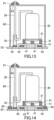
FIG. 13 is a front view illustrating a configuration of a refrigeration cycle apparatus of a second embodiment. -
FIG. 14 is a front view illustrating a first variation of the second embodiment. -
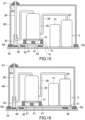
FIG. 15 is a front view illustrating a second variation of the second embodiment. -
FIG. 16 is a front view illustrating a third variation of the second embodiment. -
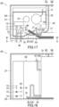
FIG. 17 is a sectional plan view illustrating pipes penetrating a soundproof box of another embodiment. -
FIG. 18 is a cross-sectional view in the direction of arrows on line A-AinFIG. 17 . -
FIG. 19 is a side view illustrating a configuration of a gas-liquid separator. - As illustrated in
FIG. 1 , a refrigeration cycle apparatus (1) includes an air conditioner unit (10) and an outdoor unit (20). The outdoor unit (20) includes a refrigerant circuit (2). The refrigerant circuit (2) is filled with, for example, a flammable natural refrigerant. The refrigerant circuit (2) circulates the refrigerant to perform a refrigeration cycle. - The air conditioner unit (10) includes an air conditioner (11). The air conditioner (11) is connected to a fluid circuit (12). A temperature adjustment fluid flows through the fluid circuit (12). The temperature adjustment fluid is, for example, water. The air conditioner (11) is installed in an indoor space to be air-conditioned.
- The fluid circuit (12) includes the air conditioner (11), a fluid pump (16), and a water heat exchanger (15) connected by a fluid pipe (17). The fluid pump (16) circulates water in the fluid circuit (12).
- The outdoor unit (20) includes the water heat exchanger (15), an outdoor heat exchanger (21), an outdoor fan (22), an outdoor expansion valve (23), a four-way switching valve (24), an accumulator (25), and a compressor (30). The outdoor heat exchanger (21), the outdoor expansion valve (23), the four-way switching valve (24), and the compressor (30) are connected by a pipe (26). The refrigerant flows through the pipe (26).
- The outdoor heat exchanger (21) is, for example, a cross-fin type fin-and-tube heat exchanger. In the outdoor heat exchanger (21), heat exchange occurs between the refrigerant flowing through the outdoor heat exchanger (21) and air blown by the outdoor fan (22). The outdoor expansion valve (23) is, for example, an electronic expansion valve.
- The compressor (30) is, for example, a rotary compressor such as a scroll compressor. The four-way switching valve (24) is connected to the pipe (26) on the discharge side of the compressor (30). The accumulator (25) is connected to the pipe (26) on the suction side of the compressor (30).
- The pipe (26) of the refrigerant circuit (2) is connected to the water heat exchanger (15). The water heat exchanger (15) causes heat exchange between the refrigerant flowing through the pipe (26) and water flowing through the fluid pipe (17).
- The four-way switching valve (24) has a first port (P1), a second port (P2), a third port (P3), and a fourth port (P4). The four-way switching valve (24) is in a state (indicated by the solid line in
FIG. 1 ) where the first port (P1) and the third port (P3) are in communication with each other, and the second port (P2) and the fourth port (P4) are in communication with each other. - The air conditioner (11) is a heat exchanger that functions as a radiator of the temperature adjustment fluid circulating in the fluid circuit (12). The air conditioner (11) is an example of a target for temperature adjustment. The air conditioner (11) is specifically a device such as a radiator or a floor cooling/heating panel. For example, when the air conditioner (11) is a radiator, the air conditioner (11) is provided near a wall or the like in the room. For example, when the air conditioner (11) is a floor cooling/heating panel, the air conditioner (11) is provided under the floor or the like of the room.
- In this embodiment, the refrigeration cycle apparatus (1) is described as a device including the refrigerant circuit (2) and the fluid circuit (12), but the refrigeration cycle apparatus (1) is not limited to this configuration. For example, the refrigeration cycle apparatus (1) may be an air conditioner including a single refrigerant circuit (2).
- As illustrated in
FIG. 2 , the outdoor unit (20) includes a body casing (27). The body casing (27) is formed in a box shape. A partitioning member (28) is disposed upright in the body casing (27). The partitioning member (28) partitions the body casing (27) into a machine chamber (S 1) and a fan chamber (S2). - The machine chamber (S1) is a space in the body casing (27) on the right side of the partitioning member (28) in
FIG. 2 . The compressor (30), the water heat exchanger (15), the four-way switching valve (24), the accumulator (25), and the pipe (26) are placed in the machine chamber (S1). - The fan chamber (S2) is a space in the body casing (27) on the left side of the partitioning member (28) in
FIG. 2 . The outdoor fan (22) and the outdoor heat exchanger (21) are placed in the fan chamber (S2). - As illustrated in
FIG. 3 , the compressor (30) includes a support leg (31). The support leg (31) is supported by a plurality of first vibration isolating members (41). The first vibration isolating members (41) are made of, for example, rubber or urethane. The first vibration isolating members (41) are supported by a first support member (51). The first support member (51) is supported by a plurality of second vibration isolating members (42). - The second vibration isolating members (42) are made of, for example, rubber or urethane. The first vibration isolating members (41) and the second vibration isolating members (42) may be made of the same material or different materials, and may have the same spring constant or different spring constants. The second vibration isolating members (42) are supported by a second support member (52). In the example shown in
FIG. 3 , the second support member (52) is a bottom plate of the body casing (27). Thus, even when the compressor (30) vibrates while the refrigeration cycle apparatus (1) is in operation, the vibration is damped by the first vibration isolating members (41) and the second vibration isolating members (42) before being transmitted to the second support member (52). - A soundproof box (60) is formed in the shape of a box that opens downward. A pipe hole (63) is formed in an upper surface of the soundproof box (60). The pipe (26) of the compressor (30) is drawn out of the soundproof box (60) through the pipe hole (63). The soundproof box (60) is supported by the second support member (52).
- According to the features of the first embodiment, the compressor (30) is covered with the soundproof box (60), keeping radiated sound and vibration sound caused by the compressor (30) from leaking outside. The compressor (30) is supported by a two-layer antivibration structure made by stacking the first vibration isolating members (41) and the second vibration isolating members (42), and the soundproof box (60) is supported by the second support member (52) to which the vibration of the compressor (30) is less transmitted. This can keep the soundproof box (60) from vibrating.
- When the bottom plate (29) of the body casing (27) of the outdoor unit (20) has an uneven top surface as illustrated in
FIG. 4 , a second support member (52) different from the bottom plate (29) may be placed on the bottom plate (29). - The support leg (31) of the compressor (30) is supported by the plurality of first vibration isolating members (41). The first vibration isolating members (41) are supported by the first support member (51). The first support member (51) is supported by the plurality of second vibration isolating members (42). The second vibration isolating members (42) are supported by the second support member (52). The second support member (52) is supported by the bottom plate (29).
- The soundproof box (60) is formed in the shape of a box that opens downward. The pipe hole (63) is formed in the upper surface of the soundproof box (60). The pipe (26) of the compressor (30) is drawn out of the soundproof box (60) through the pipe hole (63). The soundproof box (60) is supported by the second support member (52).
- According to the features of the first variation of the first embodiment, the compressor (30) can be supported by the flat surface of the first support member (51) even when the bottom plate (29) has an uneven top surface.
- As illustrated in
FIG. 5 , the soundproof box (60) may be supported by a second elastic member (65). - The support leg (31) of the compressor (30) is supported by the plurality of first vibration isolating members (41). The first vibration isolating members (41) are supported by the first support member (51). The first support member (51) is supported by the plurality of second vibration isolating members (42). The second vibration isolating members (42) are supported by the second support member (52).
- The soundproof box (60) is supported by the second elastic member (65). The second elastic member (65) is made of, for example, rubber or urethane. The second elastic member (65) is supported by the second support member (52). The pipe (26) of the compressor (30) is drawn out of the soundproof box (60) through the pipe hole (63).
- According to the features of the second variation of the first embodiment, the second elastic member (65) reduces the vibration transmitted from the compressor (30) to the second support member (52), keeping the vibration from being transmitted to the soundproof box (60).
- As illustrated in
FIG. 6 , a rigid member (35) may be provided on the pipe (26) of the compressor (30). - The support leg (31) of the compressor (30) is supported by the plurality of first vibration isolating members (41). The first vibration isolating members (41) are supported by the first support member (51). The first support member (51) is supported by the plurality of second vibration isolating members (42). The second vibration isolating members (42) are supported by the second support member (52).
- The pipe (26) is connected to the compressor (30). The pipe (26) is formed of, for example, a copper pipe. The pipe (26) is provided with the rigid member (35). The rigid member (35) is made of a material that is more rigid than the pipe (26). The rigid member (35) is made of, for example, a metal material having a specific gravity of 2.5 or more. The rigid member (35) is supported by the first support member (51).
- The soundproof box (60) is supported by the second elastic member (65). The second elastic member (65) is made of rubber or urethan. The second elastic member (65) is supported by the second support member (52). The pipe (26) of the compressor (30) is drawn out of the soundproof box (60) through the pipe hole (63).
- According to the features of the third variation of the first embodiment, the rigid member (35) reduces the vibration transmitted from the compressor (30) to the pipe (26), reducing the vibration sound generated by the vibration of the pipe (26).
- As illustrated in
FIG. 7 , the rigid member (35) may be supported by a first elastic member (36). - The support leg (31) of the compressor (30) is supported by the plurality of first vibration isolating members (41). The first vibration isolating members (41) are supported by the first support member (51). The first support member (51) is supported by the plurality of second vibration isolating members (42). The second vibration isolating members (42) are supported by the second support member (52).
- The rigid member (35) is provided on the pipe (26) of the compressor (30). The rigid member (35) is supported by the first elastic member (36). The first elastic member (36) is supported by the first support member (51).
- The soundproof box (60) is supported by the second elastic member (65). The second elastic member (65) is made of rubber or urethan. The second elastic member (65) is supported by the second support member (52). The pipe (26) of the compressor (30) is drawn out of the soundproof box (60) through the pipe hole (63).
- According to the features of the fourth variation of the first embodiment, the first elastic member (36) reduces, via the rigid member (35), the vibration transmitted from the compressor (30) to the pipe (26), reducing the transmission of the vibration to the second support member (52).
- The second elastic member (65) reduces the vibration transmitted from the compressor (30) to the second support member (52), reducing the transmission of the vibration to the soundproof box (60).
- When the vibration of the soundproof box (60) is reduced, the pipe (26) passing through the pipe hole (63) is less likely to make contact with the soundproof box (60). Thus, the diameter of the pipe hole (63) can be reduced. This can reduce sound leakage from the pipe hole (63) of the soundproof box (60).
- As illustrated in
FIG. 8 , a gap between the pipe (26) of the compressor (30) and the pipe hole (63) of the soundproof box (60) may be closed by a first lid member (61). - The support leg (31) of the compressor (30) is supported by the plurality of first vibration isolating members (41). The first vibration isolating members (41) are supported by the first support member (51). The first support member (51) is supported by the plurality of second vibration isolating members (42). The second vibration isolating members (42) are supported by the second support member (52).
- The rigid member (35) is provided on the pipe (26) of the compressor (30). The rigid member (35) is supported by the first elastic member (36). The first elastic member (36) is supported by the first support member (51).
- The soundproof box (60) is supported by the second elastic member (65). The second elastic member (65) is supported by the second support member (52). The pipe (26) of the compressor (30) is drawn out of the soundproof box (60) through the pipe hole (63).
- The first lid member (61) is attached to the pipe (26). The first lid member (61) is disposed on the upper surface of the soundproof box (60). The first lid member (61) closes the gap between the pipe (26) and the pipe hole (63). The first lid member (61) is movable along the upper surface of the soundproof box (60) as the pipe (26) vibrates.
- According to the features of the fifth variation of the first embodiment, the first lid member (61) can keep the radiated sound and the vibration sound caused by the compressor (30) from leaking from the pipe hole (63) of the soundproof box (60). Even when the pipe (26) vibrates in the pipe hole (63), the first lid member (61) moves along the surface of the soundproof box (60), keeping the gap closed.
- As illustrated in
FIG. 9 , a gap between the pipe (26) of the compressor (30) and the pipe hole (63) of the soundproof box (60) may be closed by a second lid member (62). - The support leg (31) of the compressor (30) is supported by the plurality of first vibration isolating members (41). The first vibration isolating members (41) are supported by the first support member (51). The first support member (51) is supported by the plurality of second vibration isolating members (42). The second vibration isolating members (42) are supported by the second support member (52).
- The rigid member (35) is provided on the pipe (26) of the compressor (30). The rigid member (35) is supported by the first elastic member (36). The first elastic member (36) is supported by the first support member (51).
- The soundproof box (60) is supported by the second elastic member (65). The second elastic member (65) is supported by the second support member (52). The pipe (26) of the compressor (30) is drawn out of the soundproof box (60) through the pipe hole (63).
- The second lid member (62) is attached to the pipe (26). The second lid member (62) is fitted into the pipe hole (63). The second lid member (62) closes the gap between the pipe (26) and the pipe hole (63). The second lid member (62) is formed of an elastically deformable member. The second lid member (62) is made of, for example, rubber or urethane. The second lid member (62) elastically deforms as the pipe (26) vibrates.
- According to the features of the sixth variation of the first embodiment, the second lid member (62) can keep the pipe (26) and the soundproof box (60) from making contact with each other, and can also keep the radiated sound and the vibration sound caused by the compressor (30) from leaking out of the pipe hole (63) of the soundproof box (60).
- As illustrated in
FIG. 10 , the soundproof box (60) may be provided with a sound absorber (66). - The support leg (31) of the compressor (30) is supported by the plurality of first vibration isolating members (41). The first vibration isolating members (41) are supported by the first support member (51). The first support member (51) is supported by the plurality of second vibration isolating members (42). The second vibration isolating members (42) are supported by the second support member (52).
- The rigid member (35) is provided on the pipe (26) of the compressor (30). The rigid member (35) is supported by the first elastic member (36). The first elastic member (36) is supported by the first support member (51).
- The soundproof box (60) is supported by the second elastic member (65). The second elastic member (65) is supported by the second support member (52). The pipe (26) of the compressor (30) is drawn out of the soundproof box (60) through the pipe hole (63).
- The first lid member (61) is attached to the pipe (26). The first lid member (61) is disposed on the upper surface of the soundproof box (60). The first lid member (61) closes the gap between the pipe (26) and the pipe hole (63). The first lid member (61) is movable along the upper surface of the soundproof box (60) as the pipe (26) vibrates.
- The sound absorber (66) is provided on an inner surface of the soundproof box (60). The sound absorber (66) may be provided on an outer surface of the soundproof box (60).
- According to the features of the seventh variation of the first embodiment, the sound absorber (66) provided for the soundproof box (60) can absorb the radiated sound and the vibration sound caused by the compressor (30), keeping the sounds from leaking outside.
- The soundproof box (60) provided with the sound absorber (66) is applicable to the other embodiments and variations in the same manner.
- As illustrated in
FIG. 11 , components (5) of the refrigerant circuit (2) may be disposed in the soundproof box (60). - The support leg (31) of the compressor (30) is supported by the plurality of first vibration isolating members (41). The first vibration isolating members (41) are supported by the first support member (51). The first support member (51) is supported by the plurality of second vibration isolating members (42). The second vibration isolating members (42) are supported by the second support member (52).
- The rigid member (35) is provided on the pipe (26) of the compressor (30). The rigid member (35) is supported by the first elastic member (36). The first elastic member (36) is supported by the first support member (51).
- The components (5) of the refrigerant circuit (2) include the water heat exchanger (15) and the accumulator (25). The water heat exchanger (15) and the accumulator (25) are supported by the second support member (52). The accumulator (25) is connected to the compressor (30) by the pipe (26).
- The components (5) of the refrigerant circuit (2) disposed in the soundproof box (60) may further include, for example, other components such as the four-way switching valve (24), and an electromagnetic valve, an electric valve, an economizer, and a muffler which are not shown, in addition to the water heat exchanger (15) and the accumulator (25).
- The pipe (26) connecting the compressor (30) and the accumulator (25) is covered with the soundproof box (60). The soundproof box (60) is supported by the second elastic member (65). The second elastic member (65) is supported by the second support member (52). The pipe (26) of the compressor (30) is drawn out of the soundproof box (60) through the pipe hole (63).
- The whole part of the pipe (26) connecting the compressor (30) and the accumulator (25) does not need to be disposed inside the soundproof box (60), and part of the pipe (26) may be drawn out of the soundproof box (60).
- The first lid member (61) is attached to the pipe (26). The first lid member (61) is disposed on the upper surface of the soundproof box (60). The first lid member (61) closes the gap between the pipe (26) and the pipe hole (63). The first lid member (61) is movable along the upper surface of the soundproof box (60) as the pipe (26) vibrates.
- According to the features of the eighth variation of the first embodiment, the components (5) of the refrigerant circuit (2) are disposed inside the soundproof box (60), keeping the sound of the refrigerant flowing through the refrigerant circuit (2) from leaking outside.
- According to the features of the eighth variation of the first embodiment, the pipe (26) of the compressor (30) is disposed inside the soundproof box (60). Thus, even when the vibration sound is generated by the vibration transmitted from the compressor (30) to the pipe (26), the vibration sound can be kept from leaking outside.
- As illustrated in
FIG. 12 , the components (5) of the refrigerant circuit (2) may be supported by the first support member (51). - The support leg (31) of the compressor (30) is supported by the plurality of first vibration isolating members (41). The first vibration isolating members (41) are supported by the first support member (51). The first support member (51) is supported by the plurality of second vibration isolating members (42). The second vibration isolating members (42) are supported by the second support member (52).
- The rigid member (35) is provided on the pipe (26) of the compressor (30). The rigid member (35) is supported by the first elastic member (36). The first elastic member (36) is supported by the first support member (51).
- The components (5) of the refrigerant circuit (2) include the water heat exchanger (15) and the accumulator (25). The water heat exchanger (15) and the accumulator (25) are supported by the first support member (51). The accumulator (25) is connected to the compressor (30) by the pipe (26).
- The pipe (26) connecting the compressor (30) and the accumulator (25) is covered with the soundproof box (60). The soundproof box (60) is supported by the second elastic member (65). The second elastic member (65) is supported by the second support member (52). The pipe (26) of the compressor (30) is drawn out of the soundproof box (60) through the pipe hole (63).
- The first lid member (61) is attached to the pipe (26). The first lid member (61) is disposed on the upper surface of the soundproof box (60). The first lid member (61) closes the gap between the pipe (26) and the pipe hole (63). The first lid member (61) is movable along the upper surface of the soundproof box (60) as the pipe (26) vibrates.
- According to the features of the ninth variation of the first embodiment, the components (5) of the refrigerant circuit (2) are disposed inside the soundproof box (60), keeping the sound of the refrigerant flowing through the refrigerant circuit (2) from leaking outside. Further, the overall weight of the structure supported by the first vibration isolating members (41) and the second vibration isolating members (42) is increased, improving the effect of damping the vibration.
- According to the features of the ninth variation of the first embodiment, the pipe (26) of the compressor (30) is disposed inside the soundproof box (60). Thus, even when the vibration sound is generated by the vibration transmitted from the compressor (30) to the pipe (26), the vibration sound can be kept from leaking outside.
- In the following description, the same reference characters designate the same components as those of the first embodiment, and the description will be focused only on the differences.
- As illustrated in
FIG. 13 , the rigid member (35) may be supported by the second support member (52). - The support leg (31) of the compressor (30) is supported by the plurality of first vibration isolating members (41). The first vibration isolating members (41) are supported by the first support member (51). The first support member (51) is supported by the plurality of second vibration isolating members (42). The second vibration isolating members (42) are supported by the second support member (52).
- The rigid member (35) is provided on the pipe (26) of the compressor (30). The rigid member (35) is supported by the first elastic member (36). The first elastic member (36) is supported by the second support member (52).
- The soundproof box (60) is formed in the shape of a box that opens downward. The pipe hole (63) is formed in the upper surface of the soundproof box (60). The pipe (26) of the compressor (30) is drawn out of the soundproof box (60) through the pipe hole (63). The soundproof box (60) is supported by the second support member (52).
- The first lid member (61) is attached to the pipe (26). The first lid member (61) is disposed on the upper surface of the soundproof box (60). The first lid member (61) closes the gap between the pipe (26) and the pipe hole (63). The first lid member (61) is movable along the upper surface of the soundproof box (60) as the pipe (26) vibrates.
- According to the features of the second embodiment, the compressor (30) is supported by a two-layer antivibration structure made by stacking the first vibration isolating members (41) and the second vibration isolating members (42), reducing the vibration transmitted from the compressor (30) to the second support member (52) and the vibration transmitted from the compressor (30) to the pipe (26). This can reduce the vibration sound generated by the vibration of the second support member (52) and the pipe (26).
- According to the features of the second embodiment, the rigid member (35) reduces the vibration transmitted from the compressor (30) to the pipe (26), keeping the vibration from being transmitted to the second support member (52).
- According to the features of the second embodiment, the compressor (30) is covered with the soundproof box (60), keeping the radiated sound and the vibration sound caused by the compressor (30) from leaking outside.
- As illustrated in
FIG. 14 , the soundproof box (60) may be supported by a second elastic member (65). - The support leg (31) of the compressor (30) is supported by the plurality of first vibration isolating members (41). The first vibration isolating members (41) are supported by the first support member (51). The first support member (51) is supported by the plurality of second vibration isolating members (42). The second vibration isolating members (42) are supported by the second support member (52).
- The rigid member (35) is provided on the pipe (26) of the compressor (30). The rigid member (35) is supported by the first elastic member (36). The first elastic member (36) is supported by the second support member (52).
- The soundproof box (60) is supported by the second elastic member (65). The second elastic member (65) is made of, for example, rubber or urethane. The second elastic member (65) is supported by the second support member (52). The pipe (26) of the compressor (30) is drawn out of the soundproof box (60) through the pipe hole (63).
- The first lid member (61) is attached to the pipe (26). The first lid member (61) is disposed on the upper surface of the soundproof box (60). The first lid member (61) closes the gap between the pipe (26) and the pipe hole (63). The first lid member (61) is movable along the upper surface of the soundproof box (60) as the pipe (26) vibrates.
- According to the features of the first variation of the second embodiment, the second elastic member (65) reduces the vibration transmitted from the compressor (30) to the second support member (52), keeping the vibration from being transmitted to the soundproof box (60).
- When the vibration of the soundproof box (60) is reduced, the pipe (26) passing through the pipe hole (63) is less likely to make contact with the soundproof box (60). Thus, the diameter of the pipe hole (63) can be reduced. This can reduce sound leakage from the pipe hole (63) of the soundproof box (60).
- As illustrated in
FIG. 15 , components (5) of the refrigerant circuit (2) may be disposed in the soundproof box (60). - The support leg (31) of the compressor (30) is supported by the plurality of first vibration isolating members (41). The first vibration isolating members (41) are supported by the first support member (51). The first support member (51) is supported by the plurality of second vibration isolating members (42). The second vibration isolating members (42) are supported by the second support member (52).
- The rigid member (35) is provided on the pipe (26) of the compressor (30). The rigid member (35) is supported by the first elastic member (36). The first elastic member (36) is supported by the second support member (52).
- The components (5) of the refrigerant circuit (2) include the water heat exchanger (15) and the accumulator (25). The water heat exchanger (15) and the accumulator (25) are supported by the second support member (52). The accumulator (25) is connected to the compressor (30) by the pipe (26).
- The pipe (26) connecting the compressor (30) and the accumulator (25) is covered with the soundproof box (60). The soundproof box (60) is supported by the second elastic member (65). The second elastic member (65) is supported by the second support member (52). The pipe (26) of the compressor (30) is drawn out of the soundproof box (60) through the pipe hole (63).
- The first lid member (61) is attached to the pipe (26). The first lid member (61) is disposed on the upper surface of the soundproof box (60). The first lid member (61) closes the gap between the pipe (26) and the pipe hole (63). The first lid member (61) is movable along the upper surface of the soundproof box (60) as the pipe (26) vibrates.
- According to the features of the second variation of the second embodiment, the components (5) of the refrigerant circuit (2) are disposed inside the soundproof box (60), keeping the sound of the refrigerant flowing through the refrigerant circuit (2) from leaking outside.
- According to the features of the second variation of the second embodiment, the pipe (26) of the compressor (30) is disposed inside the soundproof box (60). Thus, even when the vibration sound is generated by the vibration transmitted from the compressor (30) to the pipe (26), the vibration sound can be kept from leaking outside.
- As illustrated in
FIG. 16 , the components (5) of the refrigerant circuit (2) may be supported by the first support member (51). - The support leg (31) of the compressor (30) is supported by the plurality of first vibration isolating members (41). The first vibration isolating members (41) are supported by the first support member (51). The first support member (51) is supported by the plurality of second vibration isolating members (42). The second vibration isolating members (42) are supported by the second support member (52).
- The rigid member (35) is provided on the pipe (26) of the compressor (30). The rigid member (35) is supported by the first elastic member (36). The first elastic member (36) is supported by the second support member (52).
- The components (5) of the refrigerant circuit (2) include the water heat exchanger (15) and the accumulator (25). The water heat exchanger (15) and the accumulator (25) are supported by the first support member (51). The accumulator (25) is connected to the compressor (30) by the pipe (26).
- The pipe (26) connecting the compressor (30) and the accumulator (25) is covered with the soundproof box (60). The soundproof box (60) is supported by the second elastic member (65). The second elastic member (65) is supported by the second support member (52). The pipe (26) of the compressor (30) is drawn out of the soundproof box (60) through the pipe hole (63).
- The first lid member (61) is attached to the pipe (26). The first lid member (61) is disposed on the upper surface of the soundproof box (60). The first lid member (61) closes the gap between the pipe (26) and the pipe hole (63). The first lid member (61) is movable along the upper surface of the soundproof box (60) as the pipe (26) vibrates.
- According to the features of the third variation of the second embodiment, the components (5) of the refrigerant circuit (2) are disposed inside the soundproof box (60), keeping the sound of the refrigerant flowing through the refrigerant circuit (3) from leaking outside. Further, the overall weight of the structure supported by the first vibration isolating members (41) and the second vibration isolating members (42) is increased, improving the effect of damping the vibration.
- According to the features of the third variation of the second embodiment, the pipe (26) of the compressor (30) is disposed inside the soundproof box (60). Thus, even when the vibration sound is generated by the vibration transmitted from the compressor (30) to the pipe (26), the vibration sound can be kept from leaking outside.
- The above-described embodiments may be modified as follows.
- In this embodiment, the pipe (26) of the compressor (30) passes through the pipe hole (63) formed in the soundproof box (60). However, the present invention is not limited to this configuration.
- For example, as illustrated in
FIGS. 17 and 18 , a first pipe hole (71) may be formed in the upper surface of the soundproof box (60), and a first connection pipe (81) of the outdoor heat exchanger (21), which is an air heat exchanger, may pass through the first pipe hole (71). Here, the first connection pipe (81) is a pipe (26) connected to an outlet of an evaporator during heating operation. - Alternatively, a gap (75) may be provided between the lower edge of the soundproof box (60) and the second support member (52) serving as the bottom plate of the body casing (27), and a second connection pipe (82) of the outdoor heat exchanger (21) may pass through the gap (75). Here, the second connection pipe (82) is a pipe (26) connected to an inlet of the evaporator during heating operation. The second connection pipe (82) may have any structure of a subcooling path inlet, a flow divider inlet, and a pipe downstream of the flow divider. Note that a pipe hole (not shown) may be formed in a lower portion of a back wall surface of the soundproof box (60), and the second connection pipe (82) of the outdoor heat exchanger (21) may pass through the pipe hole.
- Alternatively, a gap (75) may be provided between the lower edge of the soundproof box (60) and the second support member (52) serving as the bottom plate of the main casing (27), and a bypass pipe (83) for bypassing hot gas may pass through the gap (75). A pipe hole (not shown) may be formed in a lower portion of a side wall surface of the soundproof box (60), and the bypass pipe (83) may pass through the pipe hole. This can avoid melting of snow or ice-up on the second support member (52) which is the bottom plate of the body casing (27).
- A water pipe hole (72) may be formed in a lower portion of the back wall surface of the soundproof box (60), and the fluid pipe (17) of the water heat exchanger (15) may pass through the water pipe hole (72).
- Further, a wire hole (73) may be formed in a front wall surface of the soundproof box (60), and a wire (85) connected to various components contained in the soundproof box (60) may be drawn out of the soundproof box (60) through the wire hole (73).
- In this case, it is preferable to attach a rubber bushing or a cable gland to the wire hole (73) to keep dust or any other foreign matters from entering the soundproof box (60) through the wire hole (73). The wire hole (73) may be formed in the back wall surface of the soundproof box (60).
- When the refrigerant circuit (2) includes the gas-liquid separator (90), the second pipe hole (74) may be formed in the back wall surface of the soundproof box (60) so that a gas release pipe (94) of the gas-liquid separator (90) passes through the second pipe hole (74).
- As illustrated in
FIG. 19 , the gas-liquid separator (90) includes a separator body (91), a pressure relief valve (92), a gas release valve (93), and a gas release pipe (94). The gas-liquid separator (90) is disposed between the water heat exchanger (15) and the air conditioner (11) in the fluid circuit (12). - The separator body (91) has a space into which water flows. The separator body (91) is, for example, a cylindrical container extending in the vertical direction. A fluid pipe (17) on the inlet side into which water having passed through the water heat exchanger (15) flows is connected to an upper portion of a side surface of the separator body (91). A fluid pipe (17) on the outlet side from which water flows toward the air conditioner (11) is connected to a lower portion of a side surface of the separator body (91).
- The pressure relief valve (92) operates to release water in the separator body (91) to the outside when the pressure in the separator body (91) reaches or exceeds a predetermined value. This regulates the pressure in the separator body (91).
- The gas release valve (93) discharges the gas flowing into the separator body (91) to the outside of the separator body (91). The gas release valve (93) includes, for example, a float-shaped valve body (not shown). The gas release valve (93) closes a discharge port (not shown) when the valve body is pushed up by water, and discharges gas from the discharge port when the gas flows into the separator body (91) to lower the liquid level and the valve body opens the discharge port.
- Here, the gas flowing into the separator body (91) is a refrigerant which has leaked from the pipe (26) connected to the water heat exchanger (15) and has entered the fluid pipe (17) of the water heat exchanger (15). The gas-liquid separator (90) is provided to discharge the refrigerant that has entered the fluid pipe (17).
- Although the configuration with only one gas release valve (93) is described in the example shown in
FIG. 19 , two gas release valves (93) may be provided. - The gas release pipe (94) is connected to the gas release valve (93). The gas release pipe (94) is, for example, a copper pipe, a resin pipe, or a hose. The gas release pipe (94) is drawn out of the soundproof box (60) through the second pipe hole (74) of the soundproof box (60).
- In this embodiment, the rigid member (35) is provided at some midpoint of the pipe (26), but the present invention is not limited to this configuration. For example, the rigid member (35) may be a manifold having a flow path hole, and the pipe (26) may be connected to the flow path hole of the rigid member (35).
- In this embodiment, the rigid member (35) is made of a block-shaped metal material, but the present invention is not limited to this configuration. For example, the accumulator (25) arranged away from the compressor (30) may be used as the rigid member (35). Specifically, the pipe (26) on the discharge side of the compressor (30) may be fixed to a side surface of the accumulator (25) so that the accumulator (25) reduces the vibration transmitted from the compressor (30) to the pipe (26) on the discharge side.
- While the embodiments and variations have been described above, it will be understood that various changes in form and details can be made without departing from the spirit and scope of the claims. The elements of the embodiments, the variations thereof, and the other embodiments may be combined and replaced with each other. In addition, the expressions of "first," "second," "third," ... , in the specification and claims are used to distinguish the terms to which these expressions are given, and do not limit the number and order of the terms.
- As can be seen in the foregoing, the present disclosure is useful for a refrigeration cycle apparatus.
-
- 1
- Refrigeration Cycle Apparatus
- 2
- Refrigerant Circuit
- 5
- Component
- 25
- Accumulator
- 26
- Pipe
- 30
- Compressor
- 35
- Rigid Member
- 36
- First Elastic Member
- 41
- First Vibration Isolating Member
- 42
- Second Vibration Isolating Member
- 51
- First Support Member
- 52
- Second Support Member
- 60
- Soundproof Box
- 61
- First Lid Member
- 62
- Second Lid Member
- 63
- Pipe Hole
- 65
- Second Elastic Member
- 66
- Sound Absorber
Claims (9)
- A refrigeration cycle apparatus including a compressor (30) and a refrigerant circuit (2) to which the compressor (30) is connected, the refrigeration cycle apparatus comprising:a first vibration isolating member (41) configured to support the compressor (30);a first support member (51) configured to support the first vibration isolating member (41);a second vibration isolating member (42) configured to support the first support member (51);a second support member (52) configured to support the second vibration isolating member (42); anda soundproof box (60) configured to cover the compressor (30),whereinthe soundproof box (60) is supported by the second support member (52).
- The refrigeration cycle apparatus of claim 1, further comprising:a second elastic member (65) configured to support the soundproof box (60),whereinthe soundproof box (60) is supported by the second elastic member (65), andthe second elastic member (65) is supported by the second support member (52).
- The refrigeration cycle apparatus of claim 1 or 2, further comprising:a rigid member (35) provided on a pipe (26) connected to the compressor (30),whereinthe rigid member (35) is supported by the first support member (51) or the second support member (52).
- The refrigeration cycle apparatus of claim 3, further comprising:a first elastic member (36) configured to support the rigid member (35),whereinthe first elastic member (36) is supported by the second support member (52).
- The refrigeration cycle apparatus of any one of claims 1 to 4, whereinthe soundproof box (60) is provided with a pipe hole (63) through which a pipe (26) of the compressor (30) passes, andthe refrigeration cycle apparatus further comprises a first lid member (61) configured to be movable along a surface of the soundproof box (60) to close a gap between the pipe (26) and the pipe hole (63).
- The refrigeration cycle apparatus of any one of claims 1 to 4, whereinthe soundproof box (60) is provided with a pipe hole (63) through which a pipe (26) of the compressor (30) passes, andthe refrigeration cycle apparatus further comprises a second lid member (62) configured to be fitted into the pipe hole (63) to close a gap between the pipe (26) and the pipe hole (63).
- The refrigeration cycle apparatus of any one of claims 1 to 6, whereina component (5) of the refrigerant circuit (2) is disposed inside the soundproof box (60), andthe component (5) includes an accumulator (25).
- The refrigeration cycle apparatus of any one of claims 1 to 7, whereina component (5) of the refrigerant circuit (2) is connected to a pipe (26) of the compressor (30), andthe pipe (26) is disposed inside the soundproof box (60).
- The refrigeration cycle apparatus of any one of claims 1 to 8, wherein
the soundproof box (60) is provided with a sound absorber (66).
Applications Claiming Priority (2)
| Application Number | Priority Date | Filing Date | Title |
|---|---|---|---|
| JP2022059342 | 2022-03-31 | ||
| PCT/JP2023/013689 WO2023191092A1 (en) | 2022-03-31 | 2023-03-31 | Refrigeration cycle device |
Publications (2)
| Publication Number | Publication Date |
|---|---|
| EP4491953A1 true EP4491953A1 (en) | 2025-01-15 |
| EP4491953A4 EP4491953A4 (en) | 2025-06-11 |
Family
ID=88202439
Family Applications (1)
| Application Number | Title | Priority Date | Filing Date |
|---|---|---|---|
| EP23781100.5A Pending EP4491953A4 (en) | 2022-03-31 | 2023-03-31 | REFRIGERATION CYCLE DEVICE |
Country Status (5)
| Country | Link |
|---|---|
| US (1) | US20250020373A1 (en) |
| EP (1) | EP4491953A4 (en) |
| JP (1) | JP2023153086A (en) |
| CN (1) | CN118765360A (en) |
| WO (1) | WO2023191092A1 (en) |
Families Citing this family (2)
| Publication number | Priority date | Publication date | Assignee | Title |
|---|---|---|---|---|
| US12616984B2 (en) * | 2023-10-16 | 2026-05-05 | Glorymakeup Inc. | Programmable air supply system with liquid cooling and noise suppression |
| DE102024138635A1 (en) * | 2024-12-18 | 2026-06-18 | Stiebel Eltron Gmbh & Co. Kg | Vibrating plate and heat pump with vibrating plate |
Family Cites Families (13)
| Publication number | Priority date | Publication date | Assignee | Title |
|---|---|---|---|---|
| JPS4852910U (en) * | 1971-10-15 | 1973-07-09 | ||
| JPS5299509U (en) * | 1976-01-26 | 1977-07-27 | ||
| JPH0297833A (en) * | 1988-10-04 | 1990-04-10 | Mitsubishi Electric Corp | Outdoor device for air conditioner |
| JPH0510843U (en) * | 1991-07-22 | 1993-02-12 | 株式会社富士通ゼネラル | Anti-vibration support device for compressor |
| JP4063112B2 (en) * | 2002-03-20 | 2008-03-19 | アイシン精機株式会社 | Engine-driven air conditioner |
| JP2004143975A (en) * | 2002-10-23 | 2004-05-20 | Hitachi Home & Life Solutions Inc | Compressor soundproofing |
| JP2005241197A (en) | 2004-02-27 | 2005-09-08 | Kimura Kohki Co Ltd | Heat pump air conditioner |
| JP5287614B2 (en) * | 2009-08-31 | 2013-09-11 | 三菱電機株式会社 | Heat pump outdoor unit |
| KR102047691B1 (en) * | 2013-02-05 | 2019-11-22 | 엘지전자 주식회사 | Air-conditioner |
| CN106091454A (en) * | 2016-07-19 | 2016-11-09 | 广东美的制冷设备有限公司 | Refrigerating plant |
| CN112074695B (en) * | 2018-05-01 | 2022-04-26 | 三菱电机株式会社 | Geothermal heat pump system |
| JPWO2022003869A1 (en) * | 2020-07-01 | 2022-01-06 | ||
| CN214619843U (en) * | 2021-04-16 | 2021-11-05 | 青岛海信日立空调系统有限公司 | An air conditioner outdoor unit |
-
2023
- 2023-03-31 JP JP2023058393A patent/JP2023153086A/en active Pending
- 2023-03-31 EP EP23781100.5A patent/EP4491953A4/en active Pending
- 2023-03-31 CN CN202380023948.6A patent/CN118765360A/en active Pending
- 2023-03-31 WO PCT/JP2023/013689 patent/WO2023191092A1/en not_active Ceased
-
2024
- 2024-09-27 US US18/898,752 patent/US20250020373A1/en active Pending
Also Published As
| Publication number | Publication date |
|---|---|
| US20250020373A1 (en) | 2025-01-16 |
| JP2023153086A (en) | 2023-10-17 |
| WO2023191092A1 (en) | 2023-10-05 |
| EP4491953A4 (en) | 2025-06-11 |
| CN118765360A (en) | 2024-10-11 |
Similar Documents
| Publication | Publication Date | Title |
|---|---|---|
| US20250020373A1 (en) | Refrigeration cycle apparatus | |
| JP6614389B1 (en) | Refrigeration equipment indoor unit | |
| CN1329638C (en) | compressor enclosure | |
| US10760796B2 (en) | Outdoor unit of air-conditioning apparatus | |
| JP2011052842A (en) | Heat pump outdoor unit | |
| EP4113019A1 (en) | Refrigeration cycle device | |
| WO2019211894A1 (en) | Geothermal heat pump system | |
| EP3745033A1 (en) | Heat pump hot water supply outdoor unit | |
| US11661941B2 (en) | Sound control for a heating, ventilation, and air conditioning unit | |
| JP4314934B2 (en) | Outdoor unit electric unit and outdoor unit of air conditioner equipped with the same | |
| US20250383100A1 (en) | Sound and vibration damping enclosures for refrigerant compressors of climate control systems | |
| JPWO2019130439A1 (en) | Heat pump hot water outdoor unit | |
| EP3514457B1 (en) | Heat source unit | |
| CN206637752U (en) | Outdoor unit of air conditioner | |
| EP4498007A1 (en) | Refrigeration cycle device | |
| US12590737B2 (en) | Refrigeration cycle apparatus | |
| KR20170064255A (en) | Outdoor unit of airconditioner | |
| JP2010261622A (en) | Air conditioning unit use side unit | |
| JP7841055B1 (en) | Outdoor unit and heat pump system equipped therewith | |
| JP7684592B2 (en) | Heat source unit and refrigeration cycle device | |
| KR20190030346A (en) | Window type air conditioner | |
| JP2025060569A (en) | Heat source unit and refrigeration cycle device | |
| JP2026049881A (en) | heat source device | |
| JP2024000765A (en) | air conditioner |
Legal Events
| Date | Code | Title | Description |
|---|---|---|---|
| STAA | Information on the status of an ep patent application or granted ep patent |
Free format text: STATUS: THE INTERNATIONAL PUBLICATION HAS BEEN MADE |
|
| PUAI | Public reference made under article 153(3) epc to a published international application that has entered the european phase |
Free format text: ORIGINAL CODE: 0009012 |
|
| STAA | Information on the status of an ep patent application or granted ep patent |
Free format text: STATUS: REQUEST FOR EXAMINATION WAS MADE |
|
| 17P | Request for examination filed |
Effective date: 20241009 |
|
| AK | Designated contracting states |
Kind code of ref document: A1 Designated state(s): AL AT BE BG CH CY CZ DE DK EE ES FI FR GB GR HR HU IE IS IT LI LT LU LV MC ME MK MT NL NO PL PT RO RS SE SI SK SM TR |
|
| A4 | Supplementary search report drawn up and despatched |
Effective date: 20250514 |
|
| RIC1 | Information provided on ipc code assigned before grant |
Ipc: F16F 15/08 20060101ALI20250508BHEP Ipc: F04B 39/00 20060101ALI20250508BHEP Ipc: F24F 13/24 20060101ALI20250508BHEP Ipc: F25B 31/00 20060101ALI20250508BHEP Ipc: F24F 1/12 20110101AFI20250508BHEP |
|
| DAV | Request for validation of the european patent (deleted) | ||
| DAX | Request for extension of the european patent (deleted) | ||
| P01 | Opt-out of the competence of the unified patent court (upc) registered |
Free format text: CASE NUMBER: UPC_APP_3798_4491953/2025 Effective date: 20250820 |
|
| STAA | Information on the status of an ep patent application or granted ep patent |
Free format text: STATUS: EXAMINATION IS IN PROGRESS |
|
| 17Q | First examination report despatched |
Effective date: 20260205 |