EP4491944A1 - Vehicle light - Google Patents
Vehicle light Download PDFInfo
- Publication number
- EP4491944A1 EP4491944A1 EP23766654.0A EP23766654A EP4491944A1 EP 4491944 A1 EP4491944 A1 EP 4491944A1 EP 23766654 A EP23766654 A EP 23766654A EP 4491944 A1 EP4491944 A1 EP 4491944A1
- Authority
- EP
- European Patent Office
- Prior art keywords
- light
- optical system
- distribution pattern
- light distribution
- main
- Prior art date
- Legal status (The legal status is an assumption and is not a legal conclusion. Google has not performed a legal analysis and makes no representation as to the accuracy of the status listed.)
- Withdrawn
Links
Images




Classifications
-
- F—MECHANICAL ENGINEERING; LIGHTING; HEATING; WEAPONS; BLASTING
- F21—LIGHTING
- F21S—NON-PORTABLE LIGHTING DEVICES; SYSTEMS THEREOF; VEHICLE LIGHTING DEVICES SPECIALLY ADAPTED FOR VEHICLE EXTERIORS
- F21S41/00—Illuminating devices specially adapted for vehicle exteriors, e.g. headlamps
- F21S41/60—Illuminating devices specially adapted for vehicle exteriors, e.g. headlamps characterised by a variable light distribution
- F21S41/67—Illuminating devices specially adapted for vehicle exteriors, e.g. headlamps characterised by a variable light distribution by acting on reflectors
- F21S41/675—Illuminating devices specially adapted for vehicle exteriors, e.g. headlamps characterised by a variable light distribution by acting on reflectors by moving reflectors
-
- B—PERFORMING OPERATIONS; TRANSPORTING
- B60—VEHICLES IN GENERAL
- B60Q—ARRANGEMENT OF SIGNALLING OR LIGHTING DEVICES, THE MOUNTING OR SUPPORTING THEREOF OR CIRCUITS THEREFOR, FOR VEHICLES IN GENERAL
- B60Q1/00—Arrangement of optical signalling or lighting devices, the mounting or supporting thereof or circuits therefor
- B60Q1/02—Arrangement of optical signalling or lighting devices, the mounting or supporting thereof or circuits therefor the devices being primarily intended to illuminate the way ahead or to illuminate other areas of way or environments
- B60Q1/04—Arrangement of optical signalling or lighting devices, the mounting or supporting thereof or circuits therefor the devices being primarily intended to illuminate the way ahead or to illuminate other areas of way or environments the devices being headlights
- B60Q1/14—Arrangement of optical signalling or lighting devices, the mounting or supporting thereof or circuits therefor the devices being primarily intended to illuminate the way ahead or to illuminate other areas of way or environments the devices being headlights having dimming means
- B60Q1/1415—Dimming circuits
- B60Q1/1423—Automatic dimming circuits, i.e. switching between high beam and low beam due to change of ambient light or light level in road traffic
- B60Q1/143—Automatic dimming circuits, i.e. switching between high beam and low beam due to change of ambient light or light level in road traffic combined with another condition, e.g. using vehicle recognition from camera images or activation of wipers
-
- F—MECHANICAL ENGINEERING; LIGHTING; HEATING; WEAPONS; BLASTING
- F21—LIGHTING
- F21S—NON-PORTABLE LIGHTING DEVICES; SYSTEMS THEREOF; VEHICLE LIGHTING DEVICES SPECIALLY ADAPTED FOR VEHICLE EXTERIORS
- F21S41/00—Illuminating devices specially adapted for vehicle exteriors, e.g. headlamps
- F21S41/10—Illuminating devices specially adapted for vehicle exteriors, e.g. headlamps characterised by the light source
- F21S41/14—Illuminating devices specially adapted for vehicle exteriors, e.g. headlamps characterised by the light source characterised by the type of light source
- F21S41/141—Light emitting diodes [LED]
- F21S41/143—Light emitting diodes [LED] the main emission direction of the LED being parallel to the optical axis of the illuminating device
-
- F—MECHANICAL ENGINEERING; LIGHTING; HEATING; WEAPONS; BLASTING
- F21—LIGHTING
- F21S—NON-PORTABLE LIGHTING DEVICES; SYSTEMS THEREOF; VEHICLE LIGHTING DEVICES SPECIALLY ADAPTED FOR VEHICLE EXTERIORS
- F21S41/00—Illuminating devices specially adapted for vehicle exteriors, e.g. headlamps
- F21S41/10—Illuminating devices specially adapted for vehicle exteriors, e.g. headlamps characterised by the light source
- F21S41/14—Illuminating devices specially adapted for vehicle exteriors, e.g. headlamps characterised by the light source characterised by the type of light source
- F21S41/141—Light emitting diodes [LED]
- F21S41/151—Light emitting diodes [LED] arranged in one or more lines
- F21S41/153—Light emitting diodes [LED] arranged in one or more lines arranged in a matrix
-
- F—MECHANICAL ENGINEERING; LIGHTING; HEATING; WEAPONS; BLASTING
- F21—LIGHTING
- F21S—NON-PORTABLE LIGHTING DEVICES; SYSTEMS THEREOF; VEHICLE LIGHTING DEVICES SPECIALLY ADAPTED FOR VEHICLE EXTERIORS
- F21S41/00—Illuminating devices specially adapted for vehicle exteriors, e.g. headlamps
- F21S41/20—Illuminating devices specially adapted for vehicle exteriors, e.g. headlamps characterised by refractors, transparent cover plates, light guides or filters
- F21S41/25—Projection lenses
- F21S41/255—Lenses with a front view of circular or truncated circular outline
-
- F—MECHANICAL ENGINEERING; LIGHTING; HEATING; WEAPONS; BLASTING
- F21—LIGHTING
- F21S—NON-PORTABLE LIGHTING DEVICES; SYSTEMS THEREOF; VEHICLE LIGHTING DEVICES SPECIALLY ADAPTED FOR VEHICLE EXTERIORS
- F21S41/00—Illuminating devices specially adapted for vehicle exteriors, e.g. headlamps
- F21S41/20—Illuminating devices specially adapted for vehicle exteriors, e.g. headlamps characterised by refractors, transparent cover plates, light guides or filters
- F21S41/25—Projection lenses
- F21S41/265—Composite lenses; Lenses with a patch-like shape
-
- F—MECHANICAL ENGINEERING; LIGHTING; HEATING; WEAPONS; BLASTING
- F21—LIGHTING
- F21S—NON-PORTABLE LIGHTING DEVICES; SYSTEMS THEREOF; VEHICLE LIGHTING DEVICES SPECIALLY ADAPTED FOR VEHICLE EXTERIORS
- F21S41/00—Illuminating devices specially adapted for vehicle exteriors, e.g. headlamps
- F21S41/20—Illuminating devices specially adapted for vehicle exteriors, e.g. headlamps characterised by refractors, transparent cover plates, light guides or filters
- F21S41/29—Attachment thereof
- F21S41/295—Attachment thereof specially adapted to projection lenses
-
- F—MECHANICAL ENGINEERING; LIGHTING; HEATING; WEAPONS; BLASTING
- F21—LIGHTING
- F21S—NON-PORTABLE LIGHTING DEVICES; SYSTEMS THEREOF; VEHICLE LIGHTING DEVICES SPECIALLY ADAPTED FOR VEHICLE EXTERIORS
- F21S41/00—Illuminating devices specially adapted for vehicle exteriors, e.g. headlamps
- F21S41/30—Illuminating devices specially adapted for vehicle exteriors, e.g. headlamps characterised by reflectors
- F21S41/32—Optical layout thereof
-
- F—MECHANICAL ENGINEERING; LIGHTING; HEATING; WEAPONS; BLASTING
- F21—LIGHTING
- F21S—NON-PORTABLE LIGHTING DEVICES; SYSTEMS THEREOF; VEHICLE LIGHTING DEVICES SPECIALLY ADAPTED FOR VEHICLE EXTERIORS
- F21S41/00—Illuminating devices specially adapted for vehicle exteriors, e.g. headlamps
- F21S41/30—Illuminating devices specially adapted for vehicle exteriors, e.g. headlamps characterised by reflectors
- F21S41/32—Optical layout thereof
- F21S41/321—Optical layout thereof the reflector being a surface of revolution or a planar surface, e.g. truncated
-
- F—MECHANICAL ENGINEERING; LIGHTING; HEATING; WEAPONS; BLASTING
- F21—LIGHTING
- F21S—NON-PORTABLE LIGHTING DEVICES; SYSTEMS THEREOF; VEHICLE LIGHTING DEVICES SPECIALLY ADAPTED FOR VEHICLE EXTERIORS
- F21S41/00—Illuminating devices specially adapted for vehicle exteriors, e.g. headlamps
- F21S41/30—Illuminating devices specially adapted for vehicle exteriors, e.g. headlamps characterised by reflectors
- F21S41/32—Optical layout thereof
- F21S41/36—Combinations of two or more separate reflectors
-
- F—MECHANICAL ENGINEERING; LIGHTING; HEATING; WEAPONS; BLASTING
- F21—LIGHTING
- F21S—NON-PORTABLE LIGHTING DEVICES; SYSTEMS THEREOF; VEHICLE LIGHTING DEVICES SPECIALLY ADAPTED FOR VEHICLE EXTERIORS
- F21S41/00—Illuminating devices specially adapted for vehicle exteriors, e.g. headlamps
- F21S41/60—Illuminating devices specially adapted for vehicle exteriors, e.g. headlamps characterised by a variable light distribution
- F21S41/65—Illuminating devices specially adapted for vehicle exteriors, e.g. headlamps characterised by a variable light distribution by acting on light sources
- F21S41/663—Illuminating devices specially adapted for vehicle exteriors, e.g. headlamps characterised by a variable light distribution by acting on light sources by switching light sources
-
- B—PERFORMING OPERATIONS; TRANSPORTING
- B60—VEHICLES IN GENERAL
- B60Q—ARRANGEMENT OF SIGNALLING OR LIGHTING DEVICES, THE MOUNTING OR SUPPORTING THEREOF OR CIRCUITS THEREFOR, FOR VEHICLES IN GENERAL
- B60Q2300/00—Indexing codes for automatically adjustable headlamps or automatically dimmable headlamps
- B60Q2300/05—Special features for controlling or switching of the light beam
- B60Q2300/056—Special anti-blinding beams, e.g. a standard beam is chopped or moved in order not to blind
-
- B—PERFORMING OPERATIONS; TRANSPORTING
- B60—VEHICLES IN GENERAL
- B60Q—ARRANGEMENT OF SIGNALLING OR LIGHTING DEVICES, THE MOUNTING OR SUPPORTING THEREOF OR CIRCUITS THEREFOR, FOR VEHICLES IN GENERAL
- B60Q2300/00—Indexing codes for automatically adjustable headlamps or automatically dimmable headlamps
- B60Q2300/40—Indexing codes relating to other road users or special conditions
- B60Q2300/42—Indexing codes relating to other road users or special conditions oncoming vehicle
-
- F—MECHANICAL ENGINEERING; LIGHTING; HEATING; WEAPONS; BLASTING
- F21—LIGHTING
- F21S—NON-PORTABLE LIGHTING DEVICES; SYSTEMS THEREOF; VEHICLE LIGHTING DEVICES SPECIALLY ADAPTED FOR VEHICLE EXTERIORS
- F21S41/00—Illuminating devices specially adapted for vehicle exteriors, e.g. headlamps
- F21S41/30—Illuminating devices specially adapted for vehicle exteriors, e.g. headlamps characterised by reflectors
-
- F—MECHANICAL ENGINEERING; LIGHTING; HEATING; WEAPONS; BLASTING
- F21—LIGHTING
- F21S—NON-PORTABLE LIGHTING DEVICES; SYSTEMS THEREOF; VEHICLE LIGHTING DEVICES SPECIALLY ADAPTED FOR VEHICLE EXTERIORS
- F21S41/00—Illuminating devices specially adapted for vehicle exteriors, e.g. headlamps
- F21S41/60—Illuminating devices specially adapted for vehicle exteriors, e.g. headlamps characterised by a variable light distribution
- F21S41/67—Illuminating devices specially adapted for vehicle exteriors, e.g. headlamps characterised by a variable light distribution by acting on reflectors
-
- F—MECHANICAL ENGINEERING; LIGHTING; HEATING; WEAPONS; BLASTING
- F21—LIGHTING
- F21W—INDEXING SCHEME ASSOCIATED WITH SUBCLASSES F21K, F21L, F21S and F21V, RELATING TO USES OR APPLICATIONS OF LIGHTING DEVICES OR SYSTEMS
- F21W2102/00—Exterior vehicle lighting devices for illuminating purposes
- F21W2102/10—Arrangement or contour of the emitted light
- F21W2102/13—Arrangement or contour of the emitted light for high-beam region or low-beam region
- F21W2102/135—Arrangement or contour of the emitted light for high-beam region or low-beam region the light having cut-off lines, i.e. clear borderlines between emitted regions and dark regions
- F21W2102/14—Arrangement or contour of the emitted light for high-beam region or low-beam region the light having cut-off lines, i.e. clear borderlines between emitted regions and dark regions having vertical cut-off lines; specially adapted for adaptive high beams, i.e. wherein the beam is broader but avoids glaring other road users
- F21W2102/15—Arrangement or contour of the emitted light for high-beam region or low-beam region the light having cut-off lines, i.e. clear borderlines between emitted regions and dark regions having vertical cut-off lines; specially adapted for adaptive high beams, i.e. wherein the beam is broader but avoids glaring other road users wherein the light is emitted under L-shaped cut-off lines, i.e. vertical and horizontal cutoff lines
-
- F—MECHANICAL ENGINEERING; LIGHTING; HEATING; WEAPONS; BLASTING
- F21—LIGHTING
- F21W—INDEXING SCHEME ASSOCIATED WITH SUBCLASSES F21K, F21L, F21S and F21V, RELATING TO USES OR APPLICATIONS OF LIGHTING DEVICES OR SYSTEMS
- F21W2102/00—Exterior vehicle lighting devices for illuminating purposes
- F21W2102/10—Arrangement or contour of the emitted light
- F21W2102/17—Arrangement or contour of the emitted light for regions other than high beam or low beam
- F21W2102/18—Arrangement or contour of the emitted light for regions other than high beam or low beam for overhead signs
-
- F—MECHANICAL ENGINEERING; LIGHTING; HEATING; WEAPONS; BLASTING
- F21—LIGHTING
- F21W—INDEXING SCHEME ASSOCIATED WITH SUBCLASSES F21K, F21L, F21S and F21V, RELATING TO USES OR APPLICATIONS OF LIGHTING DEVICES OR SYSTEMS
- F21W2102/00—Exterior vehicle lighting devices for illuminating purposes
- F21W2102/20—Illuminance distribution within the emitted light
-
- F—MECHANICAL ENGINEERING; LIGHTING; HEATING; WEAPONS; BLASTING
- F21—LIGHTING
- F21Y—INDEXING SCHEME ASSOCIATED WITH SUBCLASSES F21K, F21L, F21S and F21V, RELATING TO THE FORM OR THE KIND OF THE LIGHT SOURCES OR OF THE COLOUR OF THE LIGHT EMITTED
- F21Y2105/00—Planar light sources
- F21Y2105/10—Planar light sources comprising a two-dimensional [2D] array of point-like light-generating elements
- F21Y2105/14—Planar light sources comprising a two-dimensional [2D] array of point-like light-generating elements characterised by the overall shape of the two-dimensional [2D] array
- F21Y2105/16—Planar light sources comprising a two-dimensional [2D] array of point-like light-generating elements characterised by the overall shape of the two-dimensional [2D] array square or rectangular, e.g. for light panels
-
- F—MECHANICAL ENGINEERING; LIGHTING; HEATING; WEAPONS; BLASTING
- F21—LIGHTING
- F21Y—INDEXING SCHEME ASSOCIATED WITH SUBCLASSES F21K, F21L, F21S and F21V, RELATING TO THE FORM OR THE KIND OF THE LIGHT SOURCES OR OF THE COLOUR OF THE LIGHT EMITTED
- F21Y2115/00—Light-generating elements of semiconductor light sources
- F21Y2115/10—Light-emitting diodes [LED]
Definitions
- the present invention relates to a vehicle lamp, and particularly to a vehicle lamp suitable for use in a headlight of an automobile.
- ADB light distribution control For a headlight (headlamp) of a vehicle such as an automobile, adaptive driving beam (ADB) light distribution control has been proposed as a technique for controlling light distribution.
- the ADB light distribution control is a technique of controlling light distribution so as not to dazzle other vehicles such as oncoming vehicles and preceding vehicles and pedestrians, which are detected from, e.g., an image captured by a camera.
- a headlamp using a multi-divided light emitting element (multi-divided LED array) in which ⁇ m-order micro LEDs are arranged in a matrix as a light source has been proposed.
- Patent Literature 1 proposes a technique of using a multi-divided LED array as a light source and projecting light emitted from the multi-divided LED array by an optical system to form a light distribution pattern.
- selective light emission control is performed on micro LEDs of the multi-divided LED array so that the ADB light distribution control for forming a desired light distribution pattern can be performed.
- Patent Literature 1 JP-A-2021-068513
- Patent Literature 1 illumination by the plurality of multi-divided LED arrays is combined to illuminate a desired region with a desired brightness, but a cost is increased by the number of multi-divided LED arrays, and a composite projection lens for projecting each of the plurality of multi-divided LED arrays is required as an optical system. On this point, the cost is also increased.
- An object of the present invention is to provide a vehicle lamp capable of illuminating a desired region with a desired brightness without a complicated optical system even when a light source includes one multi-divided LED array.
- the present invention is a vehicle lamp including a light source configured such that a large number of light emitting elements are arranged, the light source selecting a light emitting element to emit light of a desired pattern, a main optical system that projects the light emitted from the light source to form a main light distribution pattern, and an auxiliary optical system that causes light which has been emitted from the light source and does not directly enter the main optical system to enter the main optical system, in which the light incident from the auxiliary optical system forms an auxiliary light distribution pattern in an external region adjacent to the main light distribution pattern.
- the auxiliary optical system is a reflecting mirror that reflects the light which has been emitted from the light source and does not directly enter the main optical system and causes the light to enter the main optical system.
- the reflecting mirror is disposed below the lens optical axis of the main optical system, and when the reflected light enters the main optical system, an upper auxiliary light distribution pattern is formed in an external region above the main light distribution pattern.
- the reflecting mirror is disposed at the side of the lens optical axis of the main optical system, and when the reflected light enters the main optical system, a right auxiliary light distribution pattern or a left auxiliary light distribution pattern is formed in an external region on the right or left side of the main light distribution pattern.
- the vehicle lamp may further include a drive mechanism that moves the reflecting mirror.
- the drive mechanism moves the reflecting mirror to a position at which the light from the light source enters the main optical system or a position at which the light from the light source does not enter the main optical system.
- the light source includes a multi-divided LED array in which a large number of micro LEDs are arranged.
- the vehicle lamp includes a controller that selectively controls light emission from the large number of micro LEDs according to a vehicle surrounding situation. The controller preferably controls a tilting mechanism.
- the main light distribution pattern is limited to a region having a required size, so that a desired brightness of the main light distribution pattern can be ensured.
- the auxiliary light distribution pattern is formed adjacent to the main light distribution pattern by light which does not contribute to formation of the main light distribution pattern, so that the main light distribution pattern and the auxiliary light distribution pattern can be combined and a region wider than a required region can be illuminated.
- FIG. 1 is a perspective view of a first embodiment in which the present invention is applied to a headlamp of an automobile, and right and left headlamps R-HL, L-HL are each attached to right and left front portions of a vehicle body of an automobile CAR.
- Each of the headlamps R-HL, L-HL includes an ADB lamp unit (hereinafter, ADB unit) ALU capable of performing ADB light distribution control, a clearance lamp unit (hereinafter, clearance unit) CLU, and a turn signal lamp unit (hereinafter, turn unit) TSLU, which are integrally arranged in a lamp housing 100.
- ADB unit ADB lamp unit
- clearance lamp unit hereinafter, clearance unit
- turn unit turn signal lamp unit
- the right and left headlamps R-HL, L-HL are configured to be bilaterally symmetrical, and Fig. 1 shows an enlarged view in which part of the right headlamp R-HL is cut away.
- the lamp housing 100 includes a lamp body 101 opened forward of the automobile and a translucent cover 102 attached to the opening, and the ADB unit ALU, the clearance unit CLU, and the turn unit TSLU are arranged in the lamp housing 100 as described above. In a region where these lamp units are not arranged, a so-called extension is disposed such that the inside of the housing is not exposed.
- a light source 3, a main optical system 2, and an auxiliary optical system 4 are incorporated into a unit case 1 of the ADB unit ALU, and the ADB unit ALU is fixed to and supported by the lamp body 101. Since the present invention relates to the ADB unit ALU, the detailed description of the clearance unit CLU and the turn unit TSLU will be omitted, but both these units have a configuration in which an LED is used as a light source and white light and amber light emitted from the LED are emitted through an inner lens made of translucent resin and are further emitted to the outside through the translucent cover 102.
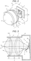
- Fig. 2 is an enlarged perspective view of the ADB unit ALU, and the unit case 1 is indicated by a chain line to show the configuration of a main portion of the ADB unit ALU.
- Fig. 3 is a longitudinal sectional view of the ADB unit ALU.
- the unit case 1 includes a lens holder 11 partially having a tubular shape and a light source box 12 integrated with the lens holder 11.
- a projection lens 2 forming the main optical system is housed in the lens holder 11, and a multi-divided LED array 3 as a light source and the auxiliary optical system 4 are arranged in the light source box 12.
- the projection lens 2 includes a triplet lens having a three-lens configuration of a convex lens 21, a concave lens 22, and a convex lens 23 having positive, negative, and positive refractive powers, and at least one lens surface of each lens is an aspherical surface. With this configuration, aberration in the projection lens 2 is suppressed, and when light from the multi-divided LED array 3 is projected through the projection lens 2, a high-resolution high-definition ADB light distribution pattern can be obtained.
- the multi-divided LED array 3 as the light source has a configuration in which hundreds to thousands of ⁇ m-order micro LEDs 31 having substantially square light emitting surfaces are planarly arranged in a matrix with the light emitting surfaces facing the same direction.
- the multi-divided LED array 3 is connected to a lamp electronic control unit (ECU) 201, and the lamp ECU 201 selectively controls the micro LEDs 31 to emit light and stop light emission.
- ECU lamp electronic control unit
- Each micro LED 31 emits white light when controlled to emit light, and the directional angle (angle at which a light intensity is halved) thereof is approximately ⁇ 30° with respect to the center axis of the light emitting surface.
- the directional angle of the entire multi-divided LED array 3 in which the plurality of micro LEDs 31 is arranged is also set to the same angle.
- the multi-divided LED array 3 is mounted on a light source substrate 30, and at a position near the focal point of the projection lens 2, an array light emitting surface (surface obtained by connecting the light emitting surfaces of the plurality of micro LEDs 31) is disposed substantially perpendicular to a lens optical axis Lx of the projection lens 2.
- the upper-lower and right-left positions of the multi-divided LED array 3 are set such that the lens optical axis Lx is located slightly shifted upward with respect to the intermediate position of the array light emitting surface in the upper-lower direction at the intermediate position of the array light emitting surface in the right-left direction.
- the ADB control unit 5 may be mounted on the light source substrate 30.
- the auxiliary optical system 4 includes a downward reflecting mirror 41 disposed on the lower front side of the array light emitting surface of the multi-divided LED array 3.
- the downward reflecting mirror 41 is formed of a cylindrical concave mirror having a gentle curvature, and is fixed and supported in the light source box 12 with its reflecting surface facing upward.
- the downward reflecting mirror 41 is disposed at a position outside the directional angle of the multi-divided LED array 3, and does not hinder light within the directional angle, which has been emitted from the multi-divided LED array 3, from entering the projection lens 2.
- the downward reflecting mirror 41 is disposed at a position at which light emitted downward at an angle greater than the directional angle enters.
- the downward reflecting mirror 41 reflects light, which has been emitted downward from the multi-divided LED array 3 at an angle outside the directional angle, in a somewhat convergent state in the upper-lower direction, and causes the light to enter the projection lens 2. At this time, the downward reflecting mirror 41 is configured to cause the light to enter a region below the optical axis Lx of the projection lens 2 at a required incident angle.
- a control switch 203 is connected to the lamp ECU 201, and when the control switch 203 is operated, the ADB unit ALU is turned on and off. When the ADB unit ALU is turned on, the ADB light distribution control is executed.
- the control switch 203 can switch auxiliary light distribution control in the ADB unit ALU to a fixed mode, an automatic mode, or a manual mode, but in the first embodiment, only the fixed mode is available.
- the lamp ECU 201 is connected to a vehicle ECU 202, and can perform the ADB light distribution control based on a signal from the vehicle ECU 202.
- the vehicle ECU 202 outputs an ADB control signal to the lamp ECU 201 based on an image of the periphery of the automobile captured by an in-vehicle camera 204, particularly an image of a front region.
- the vehicle ECU 202 analyzes the image captured by the in-vehicle camera 204 to detect an object present in front of or on the front lateral side of the automobile, such as other vehicles, a pedestrian, and a sign.
- the lamp ECU 201 In addition, information on the light distribution pattern to be controlled based on the detected object is output as the ADB control signal to the lamp ECU 201. In response to this ADB control signal, the lamp ECU 201 selects the micro LEDs 31 of the multi-divided LED array 3 and emits light.
- the lamp ECU 201 and the vehicle ECU 202 may have either a hardware configuration or a software configuration.
- the left headlamp L-HL shown in Fig. 1 has a configuration bilaterally symmetrical to the right headlamp R-HL described above, but the ADB units ALU, the clearance lamp units CLU, and the turn signal lamp units TSLU forming the right and left headlamps have basically the same configuration except for partially including a bilaterally symmetrical configuration in, e.g., a light distribution direction and a light distribution pattern.
- the control switch 203 is set to the fixed mode, and the normal ADB light distribution control is executed. That is, when the control switch 203 is turned on, the lamp ECU 201 causes the micro LEDs 31 of the multi-divided LED array 3 to emit light. As shown in some optical paths of Fig. 3 , light emitted from the multi-divided LED array 3 enters the projection lens 2, and is projected in front of the automobile by the projection lens 2. In this manner, a required light distribution pattern is formed.
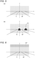
- a main light distribution pattern MP in which unit illumination cells illuminated by the micro LEDs 31 are combined is formed, as schematically shown in Fig. 5(a) .
- V is a vertical line passing through the optical axis Lx of the projection lens 2
- H is a horizontal line. That is, in the light distribution pattern, the unit illumination cells corresponding to the micro LEDs 31 forming the multi-divided LED array 3 are arranged in a matrix.
- the projection magnification of the projection lens 2 is set corresponding to the luminous intensity (luminance) of the multi-divided LED array 3 such that each unit illumination cell has a brightness required for light distribution.
- the main light distribution pattern MP is a high beam light distribution pattern which illuminates the minimum required region in normal driving, for example, a region including a subject lane and the opposite lane thereof on a road, and the brightness of the illumination region is sufficiently high.
- the ADB control signal for preventing dazzlement against the detected other vehicles is output to the lamp ECU 201.
- the lamp ECU 201 turns off the micro LEDs corresponding to the unit illumination cells in which a detected object Ob is present to prevent dazzlement against the object Ob, as schematically shown in Fig. 5(b) .
- the formed upper auxiliary light distribution pattern USP is light outside the directional angle of the multi-divided LED array, and therefore, the brightness thereof is somewhat reduced. However, since the light is converged by the downward reflecting mirror 41, the brightness can be increased accordingly.
- the main light distribution pattern MP and the upper auxiliary light distribution pattern USP are combined, and the entire illumination region of the main light distribution pattern MP is expanded. As a result, it is possible not only to control the main light distribution pattern MP to have a desired brightness, but also to expand the illumination region by combining the upper auxiliary light distribution pattern USP.
- the upper auxiliary light distribution pattern USP at the time of illumination with the main light distribution pattern MP, for example, a road sign disposed at an overhead position on the road can be illuminated by the upper auxiliary light distribution pattern USP.
- the main light distribution pattern MP is controlled to a low beam light distribution pattern, light deviated downward with respect to the projection lens 2 is reduced, and for this reason, light entering the downward reflecting mirror 41 is also reduced and it is difficult to form the upper auxiliary light distribution pattern USP.
- the upper auxiliary light distribution pattern USP can be formed by such light emission from the micro LEDs.
- the main light distribution pattern MP formed by the main optical system 2 is limited to a region having a required size, so that the main light distribution pattern MP can be controlled to have a desired brightness.
- the upper auxiliary light distribution pattern USP is formed adjacent to the upper side of the main light distribution pattern MP by light from the light source 3, which does not contribute to formation of the main light distribution pattern MP, so that the main light distribution pattern MP and the upper auxiliary light distribution pattern USP can be combined and a region wider than a required region can be illuminated.
- an existing main optical system may be used, and may simply include a reflecting mirror, so that a complicated structure can be avoided.
- Fig. 7 is a schematic perspective view of an ADB unit ALU of a right headlamp R-HL in a second embodiment
- Fig. 8 is a plan sectional view thereof.
- Elements equivalent to those in the figures of the first embodiment are denoted by the same reference numerals.
- the second embodiment includes, as the auxiliary optical system 4, a side reflecting mirror 42 which is disposed on the left side (inside in a vehicle width direction) of the multi-divided LED array 3 and is fixed and supported in the light source box 12 with a reflecting surface facing the right side (outside in the vehicle width direction).
- the side reflecting mirror 42 is disposed at a position outside the directional angle of the multi-divided LED array 3, and does not hinder light within the directional angle, which has been emitted from the multi-divided LED array 3, from entering the projection lens 2.
- the side reflecting mirror 42 is disposed at a position at which light emitted leftward from the multi-divided LED array 3 at an angle greater than the directional angle enters, and reflects the incident light in a somewhat convergent state in the horizontal direction and causes the light to enter the projection lens 2.
- the side reflecting mirror 42 is configured to cause the reflected light to enter a region inside in the vehicle width direction with respect to the optical axis Lx of the projection lens 2 at a required incident angle.
- the left headlamp L-HL shown in Fig. 1 also includes a side reflecting mirror 42, but since the left headlamp L-HL is bilaterally symmetrical to the right headlamp R-HL, an arrangement position and an arrangement direction are different. That is, the side reflecting mirror 42 is disposed on the right side which is inside the multi-divided LED array 3 in the vehicle width direction.
- the side reflecting mirror 42 reflects light, which has been emitted rightward from the multi-divided LED array 3 at an angle greater than the directional angle, in a somewhat convergent state in the horizontal direction, and causes the light to enter the projection lens 2.
- the side reflecting mirror 42 is configured to cause the reflected light to enter a region inside in the vehicle width direction with respect to the optical axis Lx of the projection lens 2 at a required incident angle.
- the main light distribution pattern MP is formed by the ADB unit ALU of the right headlamp R-HL, and a right auxiliary light distribution pattern RSP is formed on the right side of the main light distribution pattern by the side reflecting mirror 42. That is, in the ADB unit ALU, light having the directional angle deviated inward in the vehicle width direction out of light emitted from the multi-divided LED array 3 enters the side reflecting mirror 42, is reflected thereon, and enters the projection lens 2. Then, the light is emitted outward in the vehicle width direction with respect to the lens optical axis Lx from the projection lens 2, and this light forms the right auxiliary light distribution pattern RSP in an external region on the right side of the main light distribution pattern MP.
- a main light distribution pattern is formed by the ADB unit ALU of the left headlamp L-HL, and a left auxiliary light distribution pattern LSP is formed on the left side of the main light distribution pattern MP by the side reflecting mirror 42. That is, although the right and left are opposite to the ADB unit ALU of the right headlamp R-HL, light having the directional angle deviated inward in the vehicle width direction out of light emitted from the multi-divided LED array 3 enters the side reflecting mirror 42, is reflected thereon, and enters the projection lens 2. Further, the light is emitted outward in the vehicle width direction with respect to the lens optical axis Lx from the projection lens 2, and forms the left auxiliary light distribution pattern LSP in an external region on the left side of the main light distribution pattern MP.
- the main light distribution patterns MP of the ADB units ALU and the right and left auxiliary light distribution patterns RSP, LSP are combined to form a light distribution pattern in which the auxiliary light distribution patterns are formed on both sides of the main light distribution pattern as shown in Fig. 9(c) .
- the illumination region is limited by setting the main light distribution pattern MP to have a required brightness, but since the auxiliary light distribution patterns RSP, LSP on the right and left sides of the main light distribution pattern MP are combined, the light distribution pattern illumination region is expanded as a whole. That is, it is possible not only to enhance the brightness of the illumination in the main light distribution pattern MP, but also to expand the illumination region by combining the main light distribution pattern MP and the auxiliary light distribution patterns RSP, LSP.
- illumination of the right and left auxiliary light distribution patterns RSP, LSP is continued even when the ADB light distribution control is performed. Accordingly, it is possible to illuminate a region where no target is present, for example, a side region or a shoulder region on a road, with the right and left auxiliary light distribution patterns RSP, LSP. For example, when the automobile changes its traveling direction to the right and left, it is possible to illuminate a traveling destination region.
- the main light distribution pattern MP formed by the main optical system 2 is limited to a region having a required size, so that the main light distribution pattern MP can be controlled to have a desired brightness.
- the right auxiliary light distribution pattern RSP and the left auxiliary light distribution pattern LSP are formed adjacent to the right and left sides of the main light distribution pattern MP by light from the light source 3, which does not contribute to formation of the main light distribution pattern MP, so that a region wider than a required region can be illuminated.
- Fig. 10 is a schematic perspective view of an ADB unit ALU of a right headlamp R-HL in a third embodiment
- Fig. 11 is a horizontal sectional view thereof.
- the auxiliary optical system includes both the downward reflecting mirror of the first embodiment and the side reflecting mirror of the second embodiment, and further includes a tilting mechanism 43 for tilting each reflecting mirror.
- the tilting mechanism 43 includes, for example, an electromagnetic actuator, and is configured to drive a coupling lever 44 to tilt each of the reflecting mirrors 41, 42 when energized.
- Energization of the tilting mechanism 43v for tilting the downward reflecting mirror 41 and the tilting mechanism 43h for tilting the side reflecting mirror 42 is controlled by the lamp ECU 201 shown in Fig. 4 .
- the downward reflecting mirror 41 is pivotally supported by the light source box 12 through rotary shafts 41a provided at both right and left ends, and the reflecting surface thereof is turnable in the vertical direction.
- the tilting mechanism 43v is supported by the light source box 12, and a tip end portion of the coupling lever 44 is coupled to part of the downward reflecting mirror 41.
- the coupling lever 44 is driven, and by drive of the coupling lever 44, the downward reflecting mirror 41 is tilted about the rotary shafts 41a such that the angle of the reflecting surface in the vertical direction is changed.
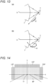
- the downward reflecting mirror 41 When the tilting mechanism 43v is not energized, the downward reflecting mirror 41 is tilted to a tilting position outside the directional angle of the multi-divided LED array 3, and not much light emitted from the multi-divided LED array 3 enters the reflecting surface, as shown in Fig. 13(a) .
- the tilting mechanism 43v when the tilting mechanism 43v is energized, the downward reflecting mirror 41 is tilted to a tilting position at which light emitted from the multi-divided LED array 3 at an angle outside the directional angle enters the reflecting surface, as shown in Fig. 13(b) . That is, the downward reflecting mirror 41 is at the same position as that of the first embodiment.
- the side reflecting mirror 42 also has a similar configuration, and is pivotally supported by the light source box 12 through rotary shafts provided at both upper and lower ends of the side reflecting mirror 42, and the reflecting surface thereof is turnable in the horizontal direction.
- a tip end portion of the coupling lever 44 of the tilting mechanism 43h is coupled to part of the side reflecting mirror 42.
- the side reflecting mirror 42 When the tilting mechanism 43h is energized, the side reflecting mirror 42 is at a tilting position at which light emitted from the multi-divided LED array 3 at an angle outside the directional angle enters the reflecting surface. That is, the side reflecting mirror 42 is at the same position as that of the second embodiment.
- a side reflecting mirror is disposed on the right side as in the second embodiment, and can be tilted by a tilting mechanism.
- the tilting mechanisms 43v, 43h of the downward reflecting mirror 41 and the side reflecting mirror 42 are energized, and the reflecting mirrors 41, 42 are brought into a state of receiving light from the multi-divided LED array 3, and the auxiliary light distribution patterns similar to those of the first embodiment and the second embodiment are formed. That is, as shown in a schematic view of Fig. 14 , the auxiliary light distribution patterns are formed on the right and left sides and upper side of the main light distribution pattern, and these are combined to form a light distribution pattern.
- the tilting mechanism 43 When the driver sets the control switch 203 to the manual mode, energization to the tilting mechanism 43 can be controlled by another switch operation by the driver. Thus, when the driver thinks necessary, the tilting mechanism 43 is driven to tilt at least one of the downward reflecting mirror 41, the side reflecting mirror 42 of the main lamp unit on the right side, or the reflecting mirror 42 of the ADB unit ALU on the left side such that light from the multi-divided LED array 3 enters the reflecting surface. Accordingly, the upper auxiliary light distribution pattern USP, the left auxiliary pattern LSP, and the right auxiliary pattern RSP shown in Fig. 14 can be arbitrarily formed.
- the side reflecting mirror 42 of the ADB unit ALU on the right side is tilted by the tilting mechanism 43h such that light from the multi-divided LED array 3 enters the reflecting surface. Accordingly, the right auxiliary light distribution pattern RSP is formed on the right side of the main light distribution pattern MP, and the illumination region of the traveling destination can be expanded.
- the lamp ECU 201 controls energization to the tilting mechanism 43 based on the ADB control signal from the vehicle ECU 202.
- the tilting mechanism 43 is driven according to the situation of an object present in front of the automobile, such as other vehicles, to tilt at least one of the downward reflecting mirror 41 or the right or left side reflecting mirror 42 such that light from the multi-divided LED array 3 enters the reflecting surface. Accordingly, the upper auxiliary light distribution pattern USP, the left auxiliary pattern LSP, and the right auxiliary pattern RSP shown in Fig. 14 can be automatically formed.
- the right or left side reflecting mirror 42 of the right or left ADB unit ALU is tilted by the tilting mechanism 43h such that light from the multi-divided LED array 3 enters the reflecting surface. Accordingly, the auxiliary light distribution patterns RSP, LSP are formed on the right and left sides of the main light distribution pattern MP, and the illumination region is expanded.
- the ADB light distribution control is performed, and energization to the tilting mechanism 43h of the side reflecting mirror 42 of each of the right and left ADB units ALU is stopped so as not to form the right and left auxiliary light distribution patterns.
- the downward reflecting mirror 41, the right and left side reflecting mirrors 42, and the tilting mechanism 43 described in the embodiment may be appropriately changed to those having other configurations. Further, the arrangement position and shape of each reflecting mirror may be set according to the light intensity characteristics of the multi-divided LED array 3.
- the downward reflecting mirror and the side reflecting mirror may be flat mirrors or convex mirrors according to the form of an auxiliary light distribution pattern to be formed.
- the downward reflecting mirror 41 may be tilted by a tilting mechanism.
- the side reflecting mirror 42 may be tilted by a tilting mechanism.
- only one of the downward reflecting mirror 41 or the side reflecting mirror 42 may include the tilting mechanism, or both the downward reflecting mirror 41 and the side reflecting mirror 42 may be reflecting mirrors having a fixed structure.
- the downward reflecting mirror 41 and the side reflecting mirror 42 only need to change their positions to positions at which light from the multi-divided LED array is not reflected, and therefore, are not necessarily tilted by the tilting mechanisms.
- these mirrors may be moved by drive mechanisms that linearly move the mirrors.
Landscapes
- Engineering & Computer Science (AREA)
- General Engineering & Computer Science (AREA)
- Physics & Mathematics (AREA)
- Microelectronics & Electronic Packaging (AREA)
- Optics & Photonics (AREA)
- Mathematical Physics (AREA)
- Mechanical Engineering (AREA)
- Non-Portable Lighting Devices Or Systems Thereof (AREA)
Abstract
Description
- The present invention relates to a vehicle lamp, and particularly to a vehicle lamp suitable for use in a headlight of an automobile.
- For a headlight (headlamp) of a vehicle such as an automobile, adaptive driving beam (ADB) light distribution control has been proposed as a technique for controlling light distribution. The ADB light distribution control is a technique of controlling light distribution so as not to dazzle other vehicles such as oncoming vehicles and preceding vehicles and pedestrians, which are detected from, e.g., an image captured by a camera. As one of the headlamps that perform the ADB light distribution control, a headlamp using a multi-divided light emitting element (multi-divided LED array) in which µm-order micro LEDs are arranged in a matrix as a light source has been proposed.
- For example,
Patent Literature 1 proposes a technique of using a multi-divided LED array as a light source and projecting light emitted from the multi-divided LED array by an optical system to form a light distribution pattern. In this technique, selective light emission control is performed on micro LEDs of the multi-divided LED array so that the ADB light distribution control for forming a desired light distribution pattern can be performed. - Patent Literature 1:
JP-A-2021-068513 - In a case where illumination is performed by one multi-divided LED array, when an illumination region is expanded by increasing a projection magnification by the optical system, the brightness (illuminance) of the illumination region decreases. In order to set the illumination region to a desired brightness, it is sufficient to reduce the projection magnification by the optical system. However, in this case, there is a trade-off that the illumination region is narrowed and an illumination region having a desired size cannot be ensured.
- In
Patent Literature 1, illumination by the plurality of multi-divided LED arrays is combined to illuminate a desired region with a desired brightness, but a cost is increased by the number of multi-divided LED arrays, and a composite projection lens for projecting each of the plurality of multi-divided LED arrays is required as an optical system. On this point, the cost is also increased. - An object of the present invention is to provide a vehicle lamp capable of illuminating a desired region with a desired brightness without a complicated optical system even when a light source includes one multi-divided LED array.
- The present invention is a vehicle lamp including a light source configured such that a large number of light emitting elements are arranged, the light source selecting a light emitting element to emit light of a desired pattern, a main optical system that projects the light emitted from the light source to form a main light distribution pattern, and an auxiliary optical system that causes light which has been emitted from the light source and does not directly enter the main optical system to enter the main optical system, in which the light incident from the auxiliary optical system forms an auxiliary light distribution pattern in an external region adjacent to the main light distribution pattern.
- In the present invention, for example, the auxiliary optical system is a reflecting mirror that reflects the light which has been emitted from the light source and does not directly enter the main optical system and causes the light to enter the main optical system. In this case, the reflecting mirror is disposed below the lens optical axis of the main optical system, and when the reflected light enters the main optical system, an upper auxiliary light distribution pattern is formed in an external region above the main light distribution pattern. The reflecting mirror is disposed at the side of the lens optical axis of the main optical system, and when the reflected light enters the main optical system, a right auxiliary light distribution pattern or a left auxiliary light distribution pattern is formed in an external region on the right or left side of the main light distribution pattern.
- In the present invention, the vehicle lamp may further include a drive mechanism that moves the reflecting mirror. The drive mechanism moves the reflecting mirror to a position at which the light from the light source enters the main optical system or a position at which the light from the light source does not enter the main optical system. In the present invention, for example, the light source includes a multi-divided LED array in which a large number of micro LEDs are arranged. Further, the vehicle lamp includes a controller that selectively controls light emission from the large number of micro LEDs according to a vehicle surrounding situation. The controller preferably controls a tilting mechanism.
- According to the present invention, the main light distribution pattern is limited to a region having a required size, so that a desired brightness of the main light distribution pattern can be ensured. On the other hand, the auxiliary light distribution pattern is formed adjacent to the main light distribution pattern by light which does not contribute to formation of the main light distribution pattern, so that the main light distribution pattern and the auxiliary light distribution pattern can be combined and a region wider than a required region can be illuminated.
-
-
Fig. 1 is a perspective view of an automobile according to a first embodiment; -
Fig. 2 is a perspective view of a main portion of a main lamp unit of the first embodiment; -
Fig. 3 is a horizontal sectional view of the main lamp unit of the first embodiment; -
Fig. 4 is a block configuration diagram of a control system of a multi-divided LED array; -
Fig. 5 is a schematic view of a main light distribution pattern and a light distribution pattern in ADB control; -
Fig. 6 is a schematic view of the main light distribution pattern combined with an upper auxiliary light distribution pattern; -
Fig. 7 is a perspective view of a main portion of a main lamp unit of a second embodiment; -
Fig. 8 is a horizontal sectional view of the main lamp unit of the second embodiment; -
Fig. 9 is a schematic view of a main light distribution pattern combined with right and left auxiliary light distribution patterns; -
Fig. 10 is a perspective view of the main portion of the main lamp unit of the second embodiment; -
Fig. 11 is a horizontal sectional view of the main lamp unit of the second embodiment; -
Fig. 12 is an enlarged perspective view of the main portion; -
Fig. 13 is a schematic view for describing operation of a reflecting mirror; and -
Fig. 14 is a schematic view of a main light distribution pattern combined with upper, right, and left auxiliary light distribution patterns. - An embodiment of the present invention will be described with reference to the drawings.
Fig. 1 is a perspective view of a first embodiment in which the present invention is applied to a headlamp of an automobile, and right and left headlamps R-HL, L-HL are each attached to right and left front portions of a vehicle body of an automobile CAR. Each of the headlamps R-HL, L-HL includes an ADB lamp unit (hereinafter, ADB unit) ALU capable of performing ADB light distribution control, a clearance lamp unit (hereinafter, clearance unit) CLU, and a turn signal lamp unit (hereinafter, turn unit) TSLU, which are integrally arranged in alamp housing 100. Note that hereinafter, the right-left direction is based on the right-left direction of the automobile. - The right and left headlamps R-HL, L-HL are configured to be bilaterally symmetrical, and
Fig. 1 shows an enlarged view in which part of the right headlamp R-HL is cut away. Thelamp housing 100 includes alamp body 101 opened forward of the automobile and atranslucent cover 102 attached to the opening, and the ADB unit ALU, the clearance unit CLU, and the turn unit TSLU are arranged in thelamp housing 100 as described above. In a region where these lamp units are not arranged, a so-called extension is disposed such that the inside of the housing is not exposed. - As will be described in detail later, a
light source 3, a mainoptical system 2, and an auxiliaryoptical system 4 are incorporated into aunit case 1 of the ADB unit ALU, and the ADB unit ALU is fixed to and supported by thelamp body 101. Since the present invention relates to the ADB unit ALU, the detailed description of the clearance unit CLU and the turn unit TSLU will be omitted, but both these units have a configuration in which an LED is used as a light source and white light and amber light emitted from the LED are emitted through an inner lens made of translucent resin and are further emitted to the outside through thetranslucent cover 102. -
Fig. 2 is an enlarged perspective view of the ADB unit ALU, and theunit case 1 is indicated by a chain line to show the configuration of a main portion of the ADB unit ALU.Fig. 3 is a longitudinal sectional view of the ADB unit ALU. As shown in these drawings, theunit case 1 includes alens holder 11 partially having a tubular shape and alight source box 12 integrated with thelens holder 11. Aprojection lens 2 forming the main optical system is housed in thelens holder 11, and amulti-divided LED array 3 as a light source and the auxiliaryoptical system 4 are arranged in thelight source box 12. - The
projection lens 2 includes a triplet lens having a three-lens configuration of aconvex lens 21, aconcave lens 22, and aconvex lens 23 having positive, negative, and positive refractive powers, and at least one lens surface of each lens is an aspherical surface. With this configuration, aberration in theprojection lens 2 is suppressed, and when light from themulti-divided LED array 3 is projected through theprojection lens 2, a high-resolution high-definition ADB light distribution pattern can be obtained. - As shown in a block configuration diagram of the multi-divided LED array and a control system thereof in
Fig. 4 , themulti-divided LED array 3 as the light source has a configuration in which hundreds to thousands of µm-order micro LEDs 31 having substantially square light emitting surfaces are planarly arranged in a matrix with the light emitting surfaces facing the same direction. Themulti-divided LED array 3 is connected to a lamp electronic control unit (ECU) 201, and thelamp ECU 201 selectively controls themicro LEDs 31 to emit light and stop light emission. Eachmicro LED 31 emits white light when controlled to emit light, and the directional angle (angle at which a light intensity is halved) thereof is approximately ±30° with respect to the center axis of the light emitting surface. Thus, the directional angle of the entiremulti-divided LED array 3 in which the plurality ofmicro LEDs 31 is arranged is also set to the same angle. - As shown in
Figs. 2 and 3 , themulti-divided LED array 3 is mounted on alight source substrate 30, and at a position near the focal point of theprojection lens 2, an array light emitting surface (surface obtained by connecting the light emitting surfaces of the plurality of micro LEDs 31) is disposed substantially perpendicular to a lens optical axis Lx of theprojection lens 2. In addition, in this embodiment, the upper-lower and right-left positions of themulti-divided LED array 3 are set such that the lens optical axis Lx is located slightly shifted upward with respect to the intermediate position of the array light emitting surface in the upper-lower direction at the intermediate position of the array light emitting surface in the right-left direction. By appropriately setting the aperture dimension of theprojection lens 2 and the dimension of the light emitting surface of themulti-divided LED array 3, light within the above-described directional angle out of light emitted from the array light emitting surface of themulti-divided LED array 3 enters theprojection lens 2. Note that the ADB control unit 5 may be mounted on thelight source substrate 30. - The auxiliary
optical system 4 includes a downward reflectingmirror 41 disposed on the lower front side of the array light emitting surface of themulti-divided LED array 3. The downward reflectingmirror 41 is formed of a cylindrical concave mirror having a gentle curvature, and is fixed and supported in thelight source box 12 with its reflecting surface facing upward. In addition, the downward reflectingmirror 41 is disposed at a position outside the directional angle of themulti-divided LED array 3, and does not hinder light within the directional angle, which has been emitted from themulti-divided LED array 3, from entering theprojection lens 2. On the other hand, the downward reflectingmirror 41 is disposed at a position at which light emitted downward at an angle greater than the directional angle enters. The downward reflectingmirror 41 reflects light, which has been emitted downward from themulti-divided LED array 3 at an angle outside the directional angle, in a somewhat convergent state in the upper-lower direction, and causes the light to enter theprojection lens 2. At this time, the downward reflectingmirror 41 is configured to cause the light to enter a region below the optical axis Lx of theprojection lens 2 at a required incident angle. - As shown in
Fig. 4 , acontrol switch 203 is connected to thelamp ECU 201, and when thecontrol switch 203 is operated, the ADB unit ALU is turned on and off. When the ADB unit ALU is turned on, the ADB light distribution control is executed. Thecontrol switch 203 can switch auxiliary light distribution control in the ADB unit ALU to a fixed mode, an automatic mode, or a manual mode, but in the first embodiment, only the fixed mode is available. - The
lamp ECU 201 is connected to avehicle ECU 202, and can perform the ADB light distribution control based on a signal from thevehicle ECU 202. Thevehicle ECU 202 outputs an ADB control signal to thelamp ECU 201 based on an image of the periphery of the automobile captured by an in-vehicle camera 204, particularly an image of a front region. Although the details of thevehicle ECU 202 will not be described, thevehicle ECU 202 analyzes the image captured by the in-vehicle camera 204 to detect an object present in front of or on the front lateral side of the automobile, such as other vehicles, a pedestrian, and a sign. In addition, information on the light distribution pattern to be controlled based on the detected object is output as the ADB control signal to thelamp ECU 201. In response to this ADB control signal, thelamp ECU 201 selects themicro LEDs 31 of themulti-divided LED array 3 and emits light. Thelamp ECU 201 and thevehicle ECU 202 may have either a hardware configuration or a software configuration. - The left headlamp L-HL shown in
Fig. 1 has a configuration bilaterally symmetrical to the right headlamp R-HL described above, but the ADB units ALU, the clearance lamp units CLU, and the turn signal lamp units TSLU forming the right and left headlamps have basically the same configuration except for partially including a bilaterally symmetrical configuration in, e.g., a light distribution direction and a light distribution pattern. - In the ADB unit ALU of the first embodiment, the
control switch 203 is set to the fixed mode, and the normal ADB light distribution control is executed. That is, when thecontrol switch 203 is turned on, thelamp ECU 201 causes themicro LEDs 31 of themulti-divided LED array 3 to emit light. As shown in some optical paths ofFig. 3 , light emitted from themulti-divided LED array 3 enters theprojection lens 2, and is projected in front of the automobile by theprojection lens 2. In this manner, a required light distribution pattern is formed. - When substantially all the
micro LEDs 31 of themulti-divided LED array 3 emit light, a main light distribution pattern MP in which unit illumination cells illuminated by themicro LEDs 31 are combined is formed, as schematically shown inFig. 5(a) . In the figure, V is a vertical line passing through the optical axis Lx of theprojection lens 2, and H is a horizontal line. That is, in the light distribution pattern, the unit illumination cells corresponding to themicro LEDs 31 forming themulti-divided LED array 3 are arranged in a matrix. In the main light distribution pattern MP, the projection magnification of theprojection lens 2 is set corresponding to the luminous intensity (luminance) of themulti-divided LED array 3 such that each unit illumination cell has a brightness required for light distribution. Thus, the main light distribution pattern MP is a high beam light distribution pattern which illuminates the minimum required region in normal driving, for example, a region including a subject lane and the opposite lane thereof on a road, and the brightness of the illumination region is sufficiently high. - When, e.g., other vehicles present in a region in front of a subject vehicle are detected by the
vehicle ECU 202 at the time of illumination with the main light distribution pattern MP, the ADB control signal for preventing dazzlement against the detected other vehicles is output to thelamp ECU 201. Based on the ADB control signal, thelamp ECU 201 turns off the micro LEDs corresponding to the unit illumination cells in which a detected object Ob is present to prevent dazzlement against the object Ob, as schematically shown inFig. 5(b) . - As shown in
Fig. 3 , light which has been emitted at an angle outside the directional angle and does not enter theprojection lens 2 out of light emitted from themulti-divided LED array 3 becomes light which does not contribute to formation of the main light distribution pattern. Of such light, light deviated to below theprojection lens 2 enters the downward reflectingmirror 41, is reflected thereon, and enters theprojection lens 2. Since this light enters a region below the lens optical axis Lx of theprojection lens 2, the light is emitted upward from theprojection lens 2 with respect to the lens optical axis Lx. Accordingly, as schematically shown inFig. 6 , this light forms an upper auxiliary light distribution pattern USP in an external region above the main light distribution pattern MP. - The same also applies to the ADB unit ALU of the left headlamp L-HL, and since the upper auxiliary light distribution pattern USP shown in
Fig. 6 is formed, a similar light distribution pattern is obtained by combining both light distribution. The formed upper auxiliary light distribution pattern USP is light outside the directional angle of the multi-divided LED array, and therefore, the brightness thereof is somewhat reduced. However, since the light is converged by the downward reflectingmirror 41, the brightness can be increased accordingly. Thus, the main light distribution pattern MP and the upper auxiliary light distribution pattern USP are combined, and the entire illumination region of the main light distribution pattern MP is expanded. As a result, it is possible not only to control the main light distribution pattern MP to have a desired brightness, but also to expand the illumination region by combining the upper auxiliary light distribution pattern USP. - In the first embodiment, at the time of illumination with the main light distribution pattern MP, for example, a road sign disposed at an overhead position on the road can be illuminated by the upper auxiliary light distribution pattern USP. Note that when the main light distribution pattern MP is controlled to a low beam light distribution pattern, light deviated downward with respect to the
projection lens 2 is reduced, and for this reason, light entering the downward reflectingmirror 41 is also reduced and it is difficult to form the upper auxiliary light distribution pattern USP. In this case, for example, if light emission from some of themicro LEDs 31 of themulti-divided LED array 3, particularly the micro LEDs illuminating an upper edge region of the main light distribution pattern MP, is continued, the upper auxiliary light distribution pattern USP can be formed by such light emission from the micro LEDs. - As described above, in the first embodiment, the main light distribution pattern MP formed by the main
optical system 2 is limited to a region having a required size, so that the main light distribution pattern MP can be controlled to have a desired brightness. On the other hand, the upper auxiliary light distribution pattern USP is formed adjacent to the upper side of the main light distribution pattern MP by light from thelight source 3, which does not contribute to formation of the main light distribution pattern MP, so that the main light distribution pattern MP and the upper auxiliary light distribution pattern USP can be combined and a region wider than a required region can be illuminated. In addition, an existing main optical system may be used, and may simply include a reflecting mirror, so that a complicated structure can be avoided. -
Fig. 7 is a schematic perspective view of an ADB unit ALU of a right headlamp R-HL in a second embodiment, andFig. 8 is a plan sectional view thereof. Elements equivalent to those in the figures of the first embodiment are denoted by the same reference numerals. The second embodiment includes, as the auxiliaryoptical system 4, aside reflecting mirror 42 which is disposed on the left side (inside in a vehicle width direction) of themulti-divided LED array 3 and is fixed and supported in thelight source box 12 with a reflecting surface facing the right side (outside in the vehicle width direction). - As in the downward reflecting
mirror 41 of the first embodiment, theside reflecting mirror 42 is disposed at a position outside the directional angle of themulti-divided LED array 3, and does not hinder light within the directional angle, which has been emitted from themulti-divided LED array 3, from entering theprojection lens 2. On the other hand, theside reflecting mirror 42 is disposed at a position at which light emitted leftward from themulti-divided LED array 3 at an angle greater than the directional angle enters, and reflects the incident light in a somewhat convergent state in the horizontal direction and causes the light to enter theprojection lens 2. At this time, theside reflecting mirror 42 is configured to cause the reflected light to enter a region inside in the vehicle width direction with respect to the optical axis Lx of theprojection lens 2 at a required incident angle. - Note that although not shown, the left headlamp L-HL shown in
Fig. 1 also includes aside reflecting mirror 42, but since the left headlamp L-HL is bilaterally symmetrical to the right headlamp R-HL, an arrangement position and an arrangement direction are different. That is, theside reflecting mirror 42 is disposed on the right side which is inside themulti-divided LED array 3 in the vehicle width direction. Theside reflecting mirror 42 reflects light, which has been emitted rightward from themulti-divided LED array 3 at an angle greater than the directional angle, in a somewhat convergent state in the horizontal direction, and causes the light to enter theprojection lens 2. At this time, theside reflecting mirror 42 is configured to cause the reflected light to enter a region inside in the vehicle width direction with respect to the optical axis Lx of theprojection lens 2 at a required incident angle. - According to the second embodiment, as shown in
Fig. 9(a) , the main light distribution pattern MP is formed by the ADB unit ALU of the right headlamp R-HL, and a right auxiliary light distribution pattern RSP is formed on the right side of the main light distribution pattern by theside reflecting mirror 42. That is, in the ADB unit ALU, light having the directional angle deviated inward in the vehicle width direction out of light emitted from themulti-divided LED array 3 enters theside reflecting mirror 42, is reflected thereon, and enters theprojection lens 2. Then, the light is emitted outward in the vehicle width direction with respect to the lens optical axis Lx from theprojection lens 2, and this light forms the right auxiliary light distribution pattern RSP in an external region on the right side of the main light distribution pattern MP. - As shown in
Fig. 9(b) , a main light distribution pattern is formed by the ADB unit ALU of the left headlamp L-HL, and a left auxiliary light distribution pattern LSP is formed on the left side of the main light distribution pattern MP by theside reflecting mirror 42. That is, although the right and left are opposite to the ADB unit ALU of the right headlamp R-HL, light having the directional angle deviated inward in the vehicle width direction out of light emitted from themulti-divided LED array 3 enters theside reflecting mirror 42, is reflected thereon, and enters theprojection lens 2. Further, the light is emitted outward in the vehicle width direction with respect to the lens optical axis Lx from theprojection lens 2, and forms the left auxiliary light distribution pattern LSP in an external region on the left side of the main light distribution pattern MP. - Since both the right and left headlamps R-HL, L-HL are simultaneously turned on, the main light distribution patterns MP of the ADB units ALU and the right and left auxiliary light distribution patterns RSP, LSP are combined to form a light distribution pattern in which the auxiliary light distribution patterns are formed on both sides of the main light distribution pattern as shown in
Fig. 9(c) . - As described above, in the second embodiment, the illumination region is limited by setting the main light distribution pattern MP to have a required brightness, but since the auxiliary light distribution patterns RSP, LSP on the right and left sides of the main light distribution pattern MP are combined, the light distribution pattern illumination region is expanded as a whole. That is, it is possible not only to enhance the brightness of the illumination in the main light distribution pattern MP, but also to expand the illumination region by combining the main light distribution pattern MP and the auxiliary light distribution patterns RSP, LSP.
- In the second embodiment, illumination of the right and left auxiliary light distribution patterns RSP, LSP is continued even when the ADB light distribution control is performed. Accordingly, it is possible to illuminate a region where no target is present, for example, a side region or a shoulder region on a road, with the right and left auxiliary light distribution patterns RSP, LSP. For example, when the automobile changes its traveling direction to the right and left, it is possible to illuminate a traveling destination region.
- In the second embodiment, the main light distribution pattern MP formed by the main
optical system 2 is limited to a region having a required size, so that the main light distribution pattern MP can be controlled to have a desired brightness. On the other hand, the right auxiliary light distribution pattern RSP and the left auxiliary light distribution pattern LSP are formed adjacent to the right and left sides of the main light distribution pattern MP by light from thelight source 3, which does not contribute to formation of the main light distribution pattern MP, so that a region wider than a required region can be illuminated. -
Fig. 10 is a schematic perspective view of an ADB unit ALU of a right headlamp R-HL in a third embodiment, andFig. 11 is a horizontal sectional view thereof. Elements equivalent to those in the second embodiment are denoted by the same reference numerals. In the third embodiment, the auxiliary optical system includes both the downward reflecting mirror of the first embodiment and the side reflecting mirror of the second embodiment, and further includes atilting mechanism 43 for tilting each reflecting mirror. Thetilting mechanism 43 includes, for example, an electromagnetic actuator, and is configured to drive acoupling lever 44 to tilt each of the reflecting mirrors 41, 42 when energized. Energization of thetilting mechanism 43v for tilting the downward reflectingmirror 41 and thetilting mechanism 43h for tilting theside reflecting mirror 42 is controlled by thelamp ECU 201 shown inFig. 4 . - For example, as shown in
Fig. 12 , the downward reflectingmirror 41 is pivotally supported by thelight source box 12 throughrotary shafts 41a provided at both right and left ends, and the reflecting surface thereof is turnable in the vertical direction. Thetilting mechanism 43v is supported by thelight source box 12, and a tip end portion of thecoupling lever 44 is coupled to part of the downward reflectingmirror 41. When thetilting mechanism 43v is energized, thecoupling lever 44 is driven, and by drive of thecoupling lever 44, the downward reflectingmirror 41 is tilted about therotary shafts 41a such that the angle of the reflecting surface in the vertical direction is changed. - When the
tilting mechanism 43v is not energized, the downward reflectingmirror 41 is tilted to a tilting position outside the directional angle of themulti-divided LED array 3, and not much light emitted from themulti-divided LED array 3 enters the reflecting surface, as shown inFig. 13(a) . On the other hand, when thetilting mechanism 43v is energized, the downward reflectingmirror 41 is tilted to a tilting position at which light emitted from themulti-divided LED array 3 at an angle outside the directional angle enters the reflecting surface, as shown inFig. 13(b) . That is, the downward reflectingmirror 41 is at the same position as that of the first embodiment. - Although not shown in detail, the
side reflecting mirror 42 also has a similar configuration, and is pivotally supported by thelight source box 12 through rotary shafts provided at both upper and lower ends of theside reflecting mirror 42, and the reflecting surface thereof is turnable in the horizontal direction. A tip end portion of thecoupling lever 44 of thetilting mechanism 43h is coupled to part of theside reflecting mirror 42. When thetilting mechanism 43h is not energized, theside reflecting mirror 42 is tilted to a tilting position outside the directional angle of themulti-divided LED array 3, and not much light emitted from themulti-divided LED array 3 enters the reflecting surface. When thetilting mechanism 43h is energized, theside reflecting mirror 42 is at a tilting position at which light emitted from themulti-divided LED array 3 at an angle outside the directional angle enters the reflecting surface. That is, theside reflecting mirror 42 is at the same position as that of the second embodiment. - Although not shown, in the ADB unit ALU of the left headlamp L-HL, a side reflecting mirror is disposed on the right side as in the second embodiment, and can be tilted by a tilting mechanism.
- According to the third embodiment, when a driver sets the
control switch 203 to the fixed mode, the tiltingmechanisms mirror 41 and theside reflecting mirror 42 are energized, and the reflecting mirrors 41, 42 are brought into a state of receiving light from themulti-divided LED array 3, and the auxiliary light distribution patterns similar to those of the first embodiment and the second embodiment are formed. That is, as shown in a schematic view ofFig. 14 , the auxiliary light distribution patterns are formed on the right and left sides and upper side of the main light distribution pattern, and these are combined to form a light distribution pattern. - When the driver sets the
control switch 203 to the manual mode, energization to thetilting mechanism 43 can be controlled by another switch operation by the driver. Thus, when the driver thinks necessary, thetilting mechanism 43 is driven to tilt at least one of the downward reflectingmirror 41, theside reflecting mirror 42 of the main lamp unit on the right side, or the reflectingmirror 42 of the ADB unit ALU on the left side such that light from themulti-divided LED array 3 enters the reflecting surface. Accordingly, the upper auxiliary light distribution pattern USP, the left auxiliary pattern LSP, and the right auxiliary pattern RSP shown inFig. 14 can be arbitrarily formed. For example, at the time of traveling rightward, theside reflecting mirror 42 of the ADB unit ALU on the right side is tilted by thetilting mechanism 43h such that light from themulti-divided LED array 3 enters the reflecting surface. Accordingly, the right auxiliary light distribution pattern RSP is formed on the right side of the main light distribution pattern MP, and the illumination region of the traveling destination can be expanded. - When the driver sets the
control switch 203 to the automatic mode, thelamp ECU 201 controls energization to thetilting mechanism 43 based on the ADB control signal from thevehicle ECU 202. Thus, thetilting mechanism 43 is driven according to the situation of an object present in front of the automobile, such as other vehicles, to tilt at least one of the downward reflectingmirror 41 or the right or leftside reflecting mirror 42 such that light from themulti-divided LED array 3 enters the reflecting surface. Accordingly, the upper auxiliary light distribution pattern USP, the left auxiliary pattern LSP, and the right auxiliary pattern RSP shown inFig. 14 can be automatically formed. For example, when no oncoming vehicle is present, the right or leftside reflecting mirror 42 of the right or left ADB unit ALU is tilted by thetilting mechanism 43h such that light from themulti-divided LED array 3 enters the reflecting surface. Accordingly, the auxiliary light distribution patterns RSP, LSP are formed on the right and left sides of the main light distribution pattern MP, and the illumination region is expanded. When an oncoming vehicle is present, the ADB light distribution control is performed, and energization to thetilting mechanism 43h of theside reflecting mirror 42 of each of the right and left ADB units ALU is stopped so as not to form the right and left auxiliary light distribution patterns. - The downward reflecting
mirror 41, the right and left side reflecting mirrors 42, and thetilting mechanism 43 described in the embodiment may be appropriately changed to those having other configurations. Further, the arrangement position and shape of each reflecting mirror may be set according to the light intensity characteristics of themulti-divided LED array 3. For example, the downward reflecting mirror and the side reflecting mirror may be flat mirrors or convex mirrors according to the form of an auxiliary light distribution pattern to be formed. - Here, in the first embodiment, the downward reflecting
mirror 41 may be tilted by a tilting mechanism. In the second embodiment, theside reflecting mirror 42 may be tilted by a tilting mechanism. In the third embodiment, only one of the downward reflectingmirror 41 or theside reflecting mirror 42 may include the tilting mechanism, or both the downward reflectingmirror 41 and theside reflecting mirror 42 may be reflecting mirrors having a fixed structure. - In the third embodiment of the present invention, the downward reflecting
mirror 41 and theside reflecting mirror 42 only need to change their positions to positions at which light from the multi-divided LED array is not reflected, and therefore, are not necessarily tilted by the tilting mechanisms. For example, these mirrors may be moved by drive mechanisms that linearly move the mirrors. - The present international application claims priority based on
Japanese Patent Application No. 2022-034093 filed on March 7, 2022 Japanese Patent Application No. 2022-034093 - The description of the specific embodiments of the present invention is presented for the purpose of illustration. The specific embodiments are not intended to be exhaustive or to limit the invention as it is in the form described. It is obvious to those skilled in the art that many modifications and alterations are possible in light of the contents of the description above.
-
- 1 Unit Case
- 2 Main Optical System
- 3 Light Source (Multi-Divided LED Array)
- 4 Auxiliary Optical System
- 21, 22, 23 Lens
- 41 Downward Reflecting Mirror
- 42 Side Reflecting Mirror
- 43 (43v, 43h) Tilting Mechanism (Drive Mechanism)
- 100 Lamp Housing
- 201 Lamp ECU
- 202 Vehicle ECU
- ALU ADB Lamp Unit
- MP Main Light Distribution Pattern
- USP Upper Auxiliary Light Distribution Pattern
- RSP Right Auxiliary Light Distribution Pattern
- LSP Left Auxiliary Light Distribution Pattern
- Lx Lens Optical Axis
Claims (9)
- A vehicle lamp comprising:a light source configured such that a large number of light emitting elements are arranged, the light source selecting a light emitting element to emit light of a desired pattern;a main optical system that projects the light emitted from the light source to form a main light distribution pattern; andan auxiliary optical system that causes light which has been emitted from the light source and does not directly enter the main optical system to enter the main optical system,wherein the light incident from the auxiliary optical system forms an auxiliary light distribution pattern in an external region adjacent to the main light distribution pattern.
- The vehicle lamp according to claim 1, wherein the auxiliary optical system is a reflecting mirror that reflects the light which has been emitted from the light source and does not directly enter the main optical system and causes the light to enter the main optical system.
- The vehicle lamp according to claim 2, wherein the reflecting mirror is disposed below a lens optical axis of the main optical system, and when the reflected light enters the main optical system, an upper auxiliary light distribution pattern is formed in an external region above the main light distribution pattern.
- The vehicle lamp according to claim 2, wherein the reflecting mirror is disposed at a side of a lens optical axis of the main optical system, and when the reflected light enters the main optical system, a right auxiliary light distribution pattern or a left auxiliary light distribution pattern is formed in an external region on a right or left side of the main light distribution pattern.
- The vehicle lamp according to any of claims 2 to 4, further comprising: a drive mechanism that moves the reflecting mirror, wherein the drive mechanism moves the reflecting mirror to a position at which the light from the light source enters the main optical system or a position at which the light from the light source does not enter the main optical system.
- The vehicle lamp according to any of claims 1 to 4, wherein the light source is a multi-divided LED array in which a large number of micro LEDs are arranged.
- The vehicle lamp according to claim 6, further comprising: a controller that selectively controls light emission from the large number of micro LEDs according to a vehicle surrounding situation.
- The vehicle lamp according to claim 7, wherein the controller controls the movement mechanism.
- The vehicle lamp according to any of claims 1 to 4, wherein the vehicle lamp is applied to a headlamp of an automobile.
Applications Claiming Priority (2)
| Application Number | Priority Date | Filing Date | Title |
|---|---|---|---|
| JP2022034093A JP7780986B2 (en) | 2022-03-07 | 2022-03-07 | Vehicle lighting fixtures |
| PCT/JP2023/007492 WO2023171477A1 (en) | 2022-03-07 | 2023-03-01 | Vehicle light |
Publications (2)
| Publication Number | Publication Date |
|---|---|
| EP4491944A1 true EP4491944A1 (en) | 2025-01-15 |
| EP4491944A4 EP4491944A4 (en) | 2025-07-02 |
Family
ID=87935188
Family Applications (1)
| Application Number | Title | Priority Date | Filing Date |
|---|---|---|---|
| EP23766654.0A Withdrawn EP4491944A4 (en) | 2022-03-07 | 2023-03-01 | VEHICLE LIGHT |
Country Status (5)
| Country | Link |
|---|---|
| US (1) | US20250198587A1 (en) |
| EP (1) | EP4491944A4 (en) |
| JP (1) | JP7780986B2 (en) |
| CN (1) | CN118843765A (en) |
| WO (1) | WO2023171477A1 (en) |
Family Cites Families (14)
| Publication number | Priority date | Publication date | Assignee | Title |
|---|---|---|---|---|
| EP2542833B1 (en) * | 2010-03-03 | 2020-07-08 | Lumileds Holding B.V. | Collimator |
| JP5758724B2 (en) * | 2011-07-07 | 2015-08-05 | 株式会社小糸製作所 | Vehicle headlamp |
| JP6105919B2 (en) * | 2012-12-19 | 2017-03-29 | 株式会社小糸製作所 | Vehicle headlamp |
| JP2015149122A (en) * | 2014-02-04 | 2015-08-20 | 株式会社小糸製作所 | Vehicle lighting |
| JP6689198B2 (en) * | 2014-07-23 | 2020-04-28 | 株式会社小糸製作所 | Lamp unit and vehicle headlight |
| JP6448306B2 (en) * | 2014-10-24 | 2019-01-09 | 株式会社小糸製作所 | Vehicle lighting |
| EP3379139B1 (en) * | 2015-11-20 | 2025-01-22 | Koito Manufacturing Co., Ltd. | Lamp fitting unit |
| KR101830662B1 (en) * | 2016-07-06 | 2018-02-21 | 엘지전자 주식회사 | Vehicle lamp and control metohd thereof |
| JP2018058412A (en) * | 2016-10-03 | 2018-04-12 | 株式会社小糸製作所 | Vehicle lighting |
| JP7002897B2 (en) * | 2017-09-20 | 2022-02-04 | 株式会社小糸製作所 | Vehicle lighting |
| JP2022034093A (en) | 2018-12-21 | 2022-03-03 | 株式会社トクヤマ | Method of producing alkane iodide derivative |
| DE102019123515B4 (en) * | 2019-09-03 | 2024-05-16 | Automotive Lighting Reutlingen Gmbh | Motor vehicle headlight with two projection light modules of different focal length and equally wide illuminated light exit lenses |
| JP2021068513A (en) | 2019-10-18 | 2021-04-30 | 株式会社小糸製作所 | Lighting device for vehicle |
| JP7406357B2 (en) * | 2019-11-27 | 2023-12-27 | 株式会社小糸製作所 | Vehicle lights |
-
2022
- 2022-03-07 JP JP2022034093A patent/JP7780986B2/en active Active
-
2023
- 2023-03-01 EP EP23766654.0A patent/EP4491944A4/en not_active Withdrawn
- 2023-03-01 CN CN202380025636.9A patent/CN118843765A/en active Pending
- 2023-03-01 WO PCT/JP2023/007492 patent/WO2023171477A1/en not_active Ceased
- 2023-03-01 US US18/843,360 patent/US20250198587A1/en not_active Abandoned
Also Published As
| Publication number | Publication date |
|---|---|
| EP4491944A4 (en) | 2025-07-02 |
| JP2023129810A (en) | 2023-09-20 |
| JP7780986B2 (en) | 2025-12-05 |
| US20250198587A1 (en) | 2025-06-19 |
| CN118843765A (en) | 2024-10-25 |
| WO2023171477A1 (en) | 2023-09-14 |
Similar Documents
| Publication | Publication Date | Title |
|---|---|---|
| US9765938B2 (en) | Vehicle headlamp | |
| JP6114653B2 (en) | Vehicle lighting | |
| US7510310B2 (en) | Vehicle lighting device | |
| CN108343925B (en) | Vehicle headlight | |
| JP6946352B2 (en) | Vehicle lighting system, vehicle lighting control device, and vehicle lighting control method | |
| US7575352B2 (en) | Vehicular headlamp | |
| US8801242B2 (en) | Light module of motor vehicle for generating spot distribution of high-beam-light distribution and vehicle headlights having such module | |
| CN108302452B (en) | Lighting device for vehicle | |
| CN104603524B (en) | Head lamp light source and headlamp | |
| US20070041207A1 (en) | Vehicle lamp | |
| EP2772682A2 (en) | Vehicle lamp and vehicle lighting system | |
| US10480744B2 (en) | Lighting system for motor vehicles | |
| EP3733452A1 (en) | Vehicle lamp system, vehicle lamp control device, and vehicle lamp control method | |
| CN111376821A (en) | Vehicle lamp system, vehicle lamp control device, and vehicle lamp control method | |
| KR20180070750A (en) | Pixel light head lamp for vehicle | |
| EP3683495A1 (en) | Vehicle front headlight device | |
| CN114207351B (en) | Vehicle lighting | |
| CN113513734B (en) | Lamps for vehicles and vehicles including them | |
| US20250198587A1 (en) | Vehicle light | |
| JP3982411B2 (en) | Digital lighting device for vehicles | |
| EP4497633B1 (en) | Vehicular lamp system, light distribution control device, and light distribution control method | |
| KR102924117B1 (en) | Lamp for vehicle | |
| JP2015223887A (en) | Vehicle lighting fixture system | |
| WO2023176444A1 (en) | Vehicular lamp | |
| CN109476253B (en) | Motor vehicle and searchlight for motor vehicle |
Legal Events
| Date | Code | Title | Description |
|---|---|---|---|
| STAA | Information on the status of an ep patent application or granted ep patent |
Free format text: STATUS: THE INTERNATIONAL PUBLICATION HAS BEEN MADE |
|
| PUAI | Public reference made under article 153(3) epc to a published international application that has entered the european phase |
Free format text: ORIGINAL CODE: 0009012 |
|
| STAA | Information on the status of an ep patent application or granted ep patent |
Free format text: STATUS: REQUEST FOR EXAMINATION WAS MADE |
|
| 17P | Request for examination filed |
Effective date: 20240905 |
|
| AK | Designated contracting states |
Kind code of ref document: A1 Designated state(s): AL AT BE BG CH CY CZ DE DK EE ES FI FR GB GR HR HU IE IS IT LI LT LU LV MC ME MK MT NL NO PL PT RO RS SE SI SK SM TR |
|
| DAV | Request for validation of the european patent (deleted) | ||
| DAX | Request for extension of the european patent (deleted) | ||
| STAA | Information on the status of an ep patent application or granted ep patent |
Free format text: STATUS: THE APPLICATION HAS BEEN WITHDRAWN |
|
| A4 | Supplementary search report drawn up and despatched |
Effective date: 20250602 |
|
| RIC1 | Information provided on ipc code assigned before grant |
Ipc: F21W 102/13 20180101ALI20250526BHEP Ipc: F21S 41/675 20180101ALI20250526BHEP Ipc: F21S 41/663 20180101ALI20250526BHEP Ipc: F21S 41/255 20180101ALI20250526BHEP Ipc: F21Y 115/10 20160101ALI20250526BHEP Ipc: F21Y 105/10 20160101AFI20250526BHEP |
|
| 18W | Application withdrawn |
Effective date: 20250623 |