EP4491923A1 - Flow control valve - Google Patents
Flow control valve Download PDFInfo
- Publication number
- EP4491923A1 EP4491923A1 EP24178203.6A EP24178203A EP4491923A1 EP 4491923 A1 EP4491923 A1 EP 4491923A1 EP 24178203 A EP24178203 A EP 24178203A EP 4491923 A1 EP4491923 A1 EP 4491923A1
- Authority
- EP
- European Patent Office
- Prior art keywords
- throttling elements
- cross
- central part
- control element
- regulator
- Prior art date
- Legal status (The legal status is an assumption and is not a legal conclusion. Google has not performed a legal analysis and makes no representation as to the accuracy of the status listed.)
- Pending
Links
Images

Classifications
-
- F—MECHANICAL ENGINEERING; LIGHTING; HEATING; WEAPONS; BLASTING
- F16—ENGINEERING ELEMENTS AND UNITS; GENERAL MEASURES FOR PRODUCING AND MAINTAINING EFFECTIVE FUNCTIONING OF MACHINES OR INSTALLATIONS; THERMAL INSULATION IN GENERAL
- F16K—VALVES; TAPS; COCKS; ACTUATING-FLOATS; DEVICES FOR VENTING OR AERATING
- F16K3/00—Gate valves or sliding valves, i.e. cut-off apparatus with closing members having a sliding movement along the seat for opening and closing
- F16K3/02—Gate valves or sliding valves, i.e. cut-off apparatus with closing members having a sliding movement along the seat for opening and closing with flat sealing faces; Packings therefor
- F16K3/12—Gate valves or sliding valves, i.e. cut-off apparatus with closing members having a sliding movement along the seat for opening and closing with flat sealing faces; Packings therefor with wedge-shaped arrangements of sealing faces
-
- F—MECHANICAL ENGINEERING; LIGHTING; HEATING; WEAPONS; BLASTING
- F16—ENGINEERING ELEMENTS AND UNITS; GENERAL MEASURES FOR PRODUCING AND MAINTAINING EFFECTIVE FUNCTIONING OF MACHINES OR INSTALLATIONS; THERMAL INSULATION IN GENERAL
- F16K—VALVES; TAPS; COCKS; ACTUATING-FLOATS; DEVICES FOR VENTING OR AERATING
- F16K17/00—Safety valves; Equalising valves, e.g. pressure relief valves
- F16K17/20—Excess-flow valves
-
- F—MECHANICAL ENGINEERING; LIGHTING; HEATING; WEAPONS; BLASTING
- F16—ENGINEERING ELEMENTS AND UNITS; GENERAL MEASURES FOR PRODUCING AND MAINTAINING EFFECTIVE FUNCTIONING OF MACHINES OR INSTALLATIONS; THERMAL INSULATION IN GENERAL
- F16K—VALVES; TAPS; COCKS; ACTUATING-FLOATS; DEVICES FOR VENTING OR AERATING
- F16K3/00—Gate valves or sliding valves, i.e. cut-off apparatus with closing members having a sliding movement along the seat for opening and closing
- F16K3/02—Gate valves or sliding valves, i.e. cut-off apparatus with closing members having a sliding movement along the seat for opening and closing with flat sealing faces; Packings therefor
- F16K3/0209—Gate valves or sliding valves, i.e. cut-off apparatus with closing members having a sliding movement along the seat for opening and closing with flat sealing faces; Packings therefor the valve having a particular passage, e.g. provided with a filter, throttle or safety device
-
- F—MECHANICAL ENGINEERING; LIGHTING; HEATING; WEAPONS; BLASTING
- F16—ENGINEERING ELEMENTS AND UNITS; GENERAL MEASURES FOR PRODUCING AND MAINTAINING EFFECTIVE FUNCTIONING OF MACHINES OR INSTALLATIONS; THERMAL INSULATION IN GENERAL
- F16K—VALVES; TAPS; COCKS; ACTUATING-FLOATS; DEVICES FOR VENTING OR AERATING
- F16K3/00—Gate valves or sliding valves, i.e. cut-off apparatus with closing members having a sliding movement along the seat for opening and closing
- F16K3/02—Gate valves or sliding valves, i.e. cut-off apparatus with closing members having a sliding movement along the seat for opening and closing with flat sealing faces; Packings therefor
- F16K3/029—Gate valves or sliding valves, i.e. cut-off apparatus with closing members having a sliding movement along the seat for opening and closing with flat sealing faces; Packings therefor with two or more gates
-
- F—MECHANICAL ENGINEERING; LIGHTING; HEATING; WEAPONS; BLASTING
- F16—ENGINEERING ELEMENTS AND UNITS; GENERAL MEASURES FOR PRODUCING AND MAINTAINING EFFECTIVE FUNCTIONING OF MACHINES OR INSTALLATIONS; THERMAL INSULATION IN GENERAL
- F16K—VALVES; TAPS; COCKS; ACTUATING-FLOATS; DEVICES FOR VENTING OR AERATING
- F16K3/00—Gate valves or sliding valves, i.e. cut-off apparatus with closing members having a sliding movement along the seat for opening and closing
- F16K3/02—Gate valves or sliding valves, i.e. cut-off apparatus with closing members having a sliding movement along the seat for opening and closing with flat sealing faces; Packings therefor
- F16K3/03—Gate valves or sliding valves, i.e. cut-off apparatus with closing members having a sliding movement along the seat for opening and closing with flat sealing faces; Packings therefor with a closure member in the form of an iris-diaphragm
-
- F—MECHANICAL ENGINEERING; LIGHTING; HEATING; WEAPONS; BLASTING
- F16—ENGINEERING ELEMENTS AND UNITS; GENERAL MEASURES FOR PRODUCING AND MAINTAINING EFFECTIVE FUNCTIONING OF MACHINES OR INSTALLATIONS; THERMAL INSULATION IN GENERAL
- F16K—VALVES; TAPS; COCKS; ACTUATING-FLOATS; DEVICES FOR VENTING OR AERATING
- F16K47/00—Means in valves for absorbing fluid energy
- F16K47/08—Means in valves for absorbing fluid energy for decreasing pressure or noise level and having a throttling member separate from the closure member, e.g. screens, slots, labyrinths
Definitions
- the invention relates to devices for regulating the flow parameters of the working medium and can be used in equipment for the gas, petroleum, chemical, energy, metallurgical and coal industries.
- the closest to the claimed invention in terms of a set of essential features is the known ( RU 2682468, IPC F16K3/03, F16K 31/54, published on Feb 02, 2019 ) flow control valve (hereinafter referred to as the regulator) containing an actuator, a housing with a control element having inlet and outlet nozzles with through openings and movable and fixed control teeth (throttling elements), where the control teeth are located along the outer part of the flow; all the teeth are made of a streamlined shape and end in a wedge, in which the size of the angle in section is defined as 360/n, where n is the number of movable teeth, the passage of the regulator is symmetrical in cross-section in the form of a multiprong star and configured to taper to the center in the process of blocking the flow.
- the objective (technical problem) that the present invention is aimed at solving is to reduce the cost of pumping.
- the technical result attained in the implementation of the claimed invention consists in achieving optimal flow rate characteristics of the medium.
- a flow control valve containing an actuator and a housing with a control element having inlet and outlet nozzles with through openings of the same diameter and a central part located coaxially therewith between the nozzles with radially directed, longitudinally oriented throttling elements evenly located on its inner cylindrical surface: fixed ones - in the form of projections, each having the shape of a triangular tooth in cross-section, and movable throttling elements located between them, made in order to change the size of the through opening of the central part configured to enable radial (in the direction to/from the longitudinal axis of the control element) translational motion along the side walls (vertex faces) of fixed throttling elements, contacting them; where all throttling elements have a terminal part in the form of a triangular wedge with a vertex angle size of 360/n, where n is the number of movable throttling elements, the cross-section of the through opening of the central part of the control element
- the flow value is regulated as the size of the through opening of the central part of the control element changes due to the radial displacement of the movable throttling elements between the "open" and “closed” positions of the regulator.
- the cross-section of the through opening in the central part of the control element in the "open" position of the regulator is limited by the vertex faces (faces with a wedge-shaped vertex) of the throttling elements.
- the movable throttling elements move from the initial position (the "open” position of the regulator) until their vertex faces are completely closed on the longitudinal axis of the control element and their side faces are in full contact with the vertex faces of the fixed throttling elements within the central part of the control element (the "closed" position of the regulator).
- the regulator can be manufactured in both a control and an anti-surge design.
- the claimed device is the only control device that fully meets the criterion of "axial symmetry”.
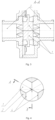
- the flow control valve contains an actuator (not shown) and a housing with control element 6 having inlet and outlet nozzles (3 and 4, respectively) of the same diameter D.
- control element 6 having inlet and outlet nozzles (3 and 4, respectively) of the same diameter D.
- central part 5 of control element 6 six radially directed longitudinally oriented throttling elements (control teeth) are evenly arranged: fixed throttling elements 2 having the shape of a triangular tooth in cross section each, made in the form of protrusions on the inner cylindrical surface of central part 5 of control element 6; and movable throttling elements 1 located between them. All throttling elements 1 and 2 have a streamlined shape and end in a wedge, whose vertex angle in section is 120°.
- the regulator is in the "open" position ( FIG. 1,2 ) when the cross-section of the through hole of central part 5 of control element 6 has the shape of a symmetrical multiprong star with an even number of prongs ( FIG. 2 ).
- the regulator is in the "closed" position ( FIG. 3, 4 ) when the vertex faces of movable throttling elements 1 are closed with each other on the longitudinal axis of control element 6.
- the inner diameter D1 of central part 5 of control element 6 is increased compared to the inner diameter D of nozzles 3 of the regulator by an amount at which the area of any cross-section of central part 5 of control element 6, taking into account the cross-sectional area of throttling elements 1, 2 in the "open" position of the regulator ( Fig. 1, 2 ) is kept within +/- 2% of the cross-sectional area of the flow part of any 3 (4) of the nozzles.
- the flow value is regulated as the size of the through opening in central part 5 of control element 6 changes as a result of radial displacement of fixed throttling elements 2 along and in contact with the side walls (vertex faces) 4 of fixed throttling elements 2 in the direction to/from its longitudinal axis.
- the translational movement of movable throttling elements 1 is ensured by rotating the wheel of the regulator actuator and transmitting this movement through a gear system to the actuator disc, with which each of movable throttling elements 1 is engaged through a mating bar.
Landscapes
- Engineering & Computer Science (AREA)
- General Engineering & Computer Science (AREA)
- Mechanical Engineering (AREA)
- Lift Valve (AREA)
Abstract
A flow control valve containing an actuator and a housing with a control element having inlet and outlet nozzles with through openings of the same diameter and a central part located coaxial therewith between the nozzles with radially directed, longitudinally oriented throttling elements evenly located on its inner cylindrical surface: fixed throttling elements (2) in the form of projections, each having the shape of a triangular tooth in cross-section, and movable throttling elements (1) located between them, made in order to change the size of the through opening of the central part configured to enable radial translational motion along the side walls of the fixed throttling elements, contacting them; where all throttling elements have a terminal part in the form of a triangular wedge with a vertex angle size of 360/n, where n is the number of movable throttling elements, the cross-section of the through opening of the central part of the control element in the "open" position of the regulator has the shape of a symmetrical multiprong star, and the inner diameter of the central part of the control element is larger than the inner diameter of any of the nozzles by an amount at which the area of any cross-section of the specified central part, taking into account the cross-sectional area of the throttling elements in the "open" position of the regulator, has a deviation from the cross-sectional area of the flow part of any of the nozzles of no more than 2%.
Description
- The invention relates to devices for regulating the flow parameters of the working medium and can be used in equipment for the gas, petroleum, chemical, energy, metallurgical and coal industries.
- The closest to the claimed invention in terms of a set of essential features is the known (
RU 2682468, IPC F16K3/03, F16K 31/54, published on Feb 02, 2019 - Attaining the technical result stated below in the known invention is impossible because of the tapering of the flow part due to the arrangement of the throttling elements. During the movement of the medium in any control mode, including in the "open" position, a change in the cross-sectional area of the flow occurs, which leads to a change in its characteristics even if this is not necessary at the moment. This results in a decrease in the flow rate characteristics of the regulator.
- The objective (technical problem) that the present invention is aimed at solving is to reduce the cost of pumping.
- The technical result attained in the implementation of the claimed invention consists in achieving optimal flow rate characteristics of the medium.
- The specified technical result is attained due to the fact that there is a flow control valve containing an actuator and a housing with a control element having inlet and outlet nozzles with through openings of the same diameter and a central part located coaxially therewith between the nozzles with radially directed, longitudinally oriented throttling elements evenly located on its inner cylindrical surface: fixed ones - in the form of projections, each having the shape of a triangular tooth in cross-section, and movable throttling elements located between them, made in order to change the size of the through opening of the central part configured to enable radial (in the direction to/from the longitudinal axis of the control element) translational motion along the side walls (vertex faces) of fixed throttling elements, contacting them; where all throttling elements have a terminal part in the form of a triangular wedge with a vertex angle size of 360/n, where n is the number of movable throttling elements, the cross-section of the through opening of the central part of the control element in the "open" position of the regulator has the shape of a symmetrical multiprong star, and the inner diameter of the central part of the control element is larger than the inner diameter of any of the nozzles by an amount at which the area of any cross-section of the specified central part, taking into account the cross-sectional area of the throttling elements in the "open" position of the regulator, has a deviation from the cross-sectional area of the flow part of any of the nozzles of no more than 2%.
- The flow value is regulated as the size of the through opening of the central part of the control element changes due to the radial displacement of the movable throttling elements between the "open" and "closed" positions of the regulator.
- The cross-section of the through opening in the central part of the control element in the "open" position of the regulator is limited by the vertex faces (faces with a wedge-shaped vertex) of the throttling elements. In the process of regulating the flow value, the movable throttling elements move from the initial position (the "open" position of the regulator) until their vertex faces are completely closed on the longitudinal axis of the control element and their side faces are in full contact with the vertex faces of the fixed throttling elements within the central part of the control element (the "closed" position of the regulator).
- An increase in the volume of the central part of the control element due to an increase in its inner diameter compensates for the volume occupied in this part by the throttling elements. As a result of such compensation, the cross-sectional area of the through opening at any point along the entire control zone (the central part of the control element) in the "open" position of the regulator remains the same or has minor (within 2%) deviations. At the same time, equal or very similar characteristics of the change in the shape and cross-sectional area of the through opening are achieved, which leads to optimization of the flow of the medium through the regulator in the "open" position to the characteristics of the medium flow in the pipe. In other words, in the open state, the throughput of the regulator is equal to (or differs by no more than 2% from) the throughput of the pipeline on which the regulator is installed.
- These changes in the through opening, characterized by a throughput coefficient, allow the flow of the medium to retain exactly the same characteristics (volume and speed) both upstream and downstream the control element. Due to the absence of changes in the specified characteristics of the medium flow in the "open" position of the regulator, pumping costs are reduced many times over.
- Depending on the actuator used, the regulator can be manufactured in both a control and an anti-surge design.
- The claimed device is the only control device that fully meets the criterion of "axial symmetry".
- To clarify the essence of the claimed invention, the following graphic materials are presented:
-
FIG. 1 is a longitudinal section of the regulator housing, with the through opening of the flow part in the "open" position of the regulator; -
FIG. 2 is section B-B of the central part of the regulator, with the through hole of the flow part in the "open" position of the regulator; -
FIG. 3 is a longitudinal section of the central part of the regulator, with the through hole of the flow part in the "closed" position of the regulator; -
FIG. 4 is section A-A of the central part of the control element, with the through opening of the flow part in the "closed" position of the regulator; - To prove the industrial implementation of the claimed invention, a description of a particular design of the flow control valve and the way of its functioning are presented.
- The flow control valve contains an actuator (not shown) and a housing with
control element 6 having inlet and outlet nozzles (3 and 4, respectively) of the same diameter D. In central part 5 ofcontrol element 6, six radially directed longitudinally oriented throttling elements (control teeth) are evenly arranged: fixedthrottling elements 2 having the shape of a triangular tooth in cross section each, made in the form of protrusions on the inner cylindrical surface of central part 5 ofcontrol element 6; andmovable throttling elements 1 located between them. Allthrottling elements - The regulator is in the "open" position (
FIG. 1,2 ) when the cross-section of the through hole of central part 5 ofcontrol element 6 has the shape of a symmetrical multiprong star with an even number of prongs (FIG. 2 ). - The regulator is in the "closed" position (
FIG. 3, 4 ) when the vertex faces ofmovable throttling elements 1 are closed with each other on the longitudinal axis ofcontrol element 6. - The inner diameter D1 of central part 5 of
control element 6 is increased compared to the inner diameter D ofnozzles 3 of the regulator by an amount at which the area of any cross-section of central part 5 ofcontrol element 6, taking into account the cross-sectional area ofthrottling elements Fig. 1, 2 ) is kept within +/- 2% of the cross-sectional area of the flow part of any 3 (4) of the nozzles. - The flow value is regulated as the size of the through opening in central part 5 of
control element 6 changes as a result of radial displacement of fixedthrottling elements 2 along and in contact with the side walls (vertex faces) 4 of fixedthrottling elements 2 in the direction to/from its longitudinal axis. The translational movement ofmovable throttling elements 1 is ensured by rotating the wheel of the regulator actuator and transmitting this movement through a gear system to the actuator disc, with which each ofmovable throttling elements 1 is engaged through a mating bar.
Claims (1)
- A flow control valve (regulator) containing an actuator and a housing with a control element having inlet and outlet nozzles with through openings of the same diameter and a central part located coaxial therewith between the nozzles with radially directed, longitudinally oriented throttling elements evenly located on its inner cylindrical surface: fixed ones - in the form of projections, each having the shape of a triangular tooth in cross-section, and movable throttling elements located between them, made in order to change the size of the through opening of the central part configured to enable radial (in the direction to/from the longitudinal axis of the control element) translational motion along the side walls (vertex faces) of fixed throttling elements, contacting them; where all throttling elements have a terminal part in the form of a triangular wedge with a vertex angle size of 360/n, where n is the number of movable throttling elements, the cross-section of the through opening of the central part of the control element in the "open" position of the regulator has the shape of a symmetrical multiprong star, and the inner diameter of the central part of the control element is larger than the inner diameter of any of the nozzles by an amount at which the area of any cross-section of the specified central part, taking into account the cross-sectional area of the throttling elements in the "open" position of the regulator, has a deviation from the cross-sectional area of the flow part of any of the nozzles of no more than 2%.
Applications Claiming Priority (1)
| Application Number | Priority Date | Filing Date | Title |
|---|---|---|---|
| RU2023118418A RU2806943C1 (en) | 2023-07-12 | Flow control valve |
Publications (1)
| Publication Number | Publication Date |
|---|---|
| EP4491923A1 true EP4491923A1 (en) | 2025-01-15 |
Family
ID=91375231
Family Applications (1)
| Application Number | Title | Priority Date | Filing Date |
|---|---|---|---|
| EP24178203.6A Pending EP4491923A1 (en) | 2023-07-12 | 2024-05-27 | Flow control valve |
Country Status (3)
| Country | Link |
|---|---|
| US (1) | US12535142B2 (en) |
| EP (1) | EP4491923A1 (en) |
| CN (1) | CN119309042A (en) |
Citations (3)
| Publication number | Priority date | Publication date | Assignee | Title |
|---|---|---|---|---|
| KR20050014360A (en) * | 2003-07-31 | 2005-02-07 | 양현태 | Flow control valve |
| RU2682468C2 (en) * | 2017-08-18 | 2019-03-19 | Вадим Михайлович Сакизчи | Flow control valve |
| US11415231B2 (en) * | 2018-05-03 | 2022-08-16 | Vadim M. SAKIZCHI | Flow regulating valve |
Family Cites Families (12)
| Publication number | Priority date | Publication date | Assignee | Title |
|---|---|---|---|---|
| US1999699A (en) * | 1933-11-22 | 1935-04-30 | Koch Robert | Well capping device |
| US2132037A (en) * | 1936-03-30 | 1938-10-04 | Macclatchie Mfg Company Of Cal | Blow-out preventer |
| US2333423A (en) * | 1941-09-29 | 1943-11-02 | Thompson Prod Inc | Quick disconnect coupling |
| US3084898A (en) * | 1960-02-04 | 1963-04-09 | Charles W Mccallum | Fluid actuated valve |
| US3136525A (en) * | 1962-02-19 | 1964-06-09 | Walworth Co | Center flow in-line valve |
| US5524863A (en) * | 1994-06-08 | 1996-06-11 | Daniel Industries, Inc. | Quarter turn rotatable flow control valve |
| GB9521252D0 (en) * | 1995-10-17 | 1995-12-20 | Bishopbarn Ltd | Improvements in and relating to weighing machines |
| US5680889A (en) * | 1996-09-23 | 1997-10-28 | Dresser Industries, Inc. | Low noise ball valve assembly |
| US20150083943A1 (en) * | 2013-09-24 | 2015-03-26 | Tokyo Electron Limited | Quadruple RAM BOP |
| BE1022401B1 (en) * | 2014-09-19 | 2016-03-24 | Atlas Copco Airpower, Naamloze Vennootschap | INTAKE VALVE FOR A COMPRESSOR |
| CA2999364C (en) * | 2017-05-19 | 2023-02-21 | Vadim Mihajlovich SAKIZCHI | Flow control valve |
| US11261975B2 (en) * | 2020-05-08 | 2022-03-01 | Fisher Controls International, Llc | Pressure-reduction devices for fluid systems |
-
2024
- 2024-03-28 CN CN202410363982.4A patent/CN119309042A/en active Pending
- 2024-05-27 EP EP24178203.6A patent/EP4491923A1/en active Pending
- 2024-07-01 US US18/761,108 patent/US12535142B2/en active Active
Patent Citations (3)
| Publication number | Priority date | Publication date | Assignee | Title |
|---|---|---|---|---|
| KR20050014360A (en) * | 2003-07-31 | 2005-02-07 | 양현태 | Flow control valve |
| RU2682468C2 (en) * | 2017-08-18 | 2019-03-19 | Вадим Михайлович Сакизчи | Flow control valve |
| US11415231B2 (en) * | 2018-05-03 | 2022-08-16 | Vadim M. SAKIZCHI | Flow regulating valve |
Also Published As
| Publication number | Publication date |
|---|---|
| US20250020220A1 (en) | 2025-01-16 |
| US12535142B2 (en) | 2026-01-27 |
| CN119309042A (en) | 2025-01-14 |
Similar Documents
| Publication | Publication Date | Title |
|---|---|---|
| EP2310731B1 (en) | Choke valve with flow impeding recesses | |
| US10605370B2 (en) | Valve trim apparatus for use with control valves | |
| EP2914889B1 (en) | Valve cage having zero dead band between noise abatement and high capacity flow sections | |
| EP2547936B1 (en) | Valves having ceramic trim with protected shut-off surfaces | |
| US8585011B2 (en) | Control valve trim | |
| US11261975B2 (en) | Pressure-reduction devices for fluid systems | |
| EP2888512B1 (en) | Axial fluid valves with annular flow control members | |
| US11209100B2 (en) | Valve trim apparatus for use with valves | |
| US11015721B2 (en) | Flow control valve | |
| EP3433521A1 (en) | Cage apparatus having fluid passageways to affect flow characteristics of valves | |
| CN109519580B (en) | Control valve with guide vanes | |
| US10378309B2 (en) | Choke valve trim | |
| US5890505A (en) | Low noise ball valve assembly with downstream airfoil insert | |
| RU2422709C1 (en) | Control valve for hot gas flow rate | |
| EP4491923A1 (en) | Flow control valve | |
| RU2806943C1 (en) | Flow control valve | |
| US20250043870A1 (en) | Fluid flow control devices and related systems and methods | |
| US20210180704A1 (en) | Flow Regulating Valve | |
| RU2842877C1 (en) | Flow control valve | |
| CN121594193A (en) | Regulating valve |
Legal Events
| Date | Code | Title | Description |
|---|---|---|---|
| PUAI | Public reference made under article 153(3) epc to a published international application that has entered the european phase |
Free format text: ORIGINAL CODE: 0009012 |
|
| STAA | Information on the status of an ep patent application or granted ep patent |
Free format text: STATUS: REQUEST FOR EXAMINATION WAS MADE |
|
| 17P | Request for examination filed |
Effective date: 20240528 |
|
| AK | Designated contracting states |
Kind code of ref document: A1 Designated state(s): AL AT BE BG CH CY CZ DE DK EE ES FI FR GB GR HR HU IE IS IT LI LT LU LV MC ME MK MT NL NO PL PT RO RS SE SI SK SM TR |