EP4491907A1 - Nut for actuator system and actuator system comprising the same - Google Patents
Nut for actuator system and actuator system comprising the same Download PDFInfo
- Publication number
- EP4491907A1 EP4491907A1 EP24187703.4A EP24187703A EP4491907A1 EP 4491907 A1 EP4491907 A1 EP 4491907A1 EP 24187703 A EP24187703 A EP 24187703A EP 4491907 A1 EP4491907 A1 EP 4491907A1
- Authority
- EP
- European Patent Office
- Prior art keywords
- nut portion
- nut
- threads
- screw
- outer nut
- Prior art date
- Legal status (The legal status is an assumption and is not a legal conclusion. Google has not performed a legal analysis and makes no representation as to the accuracy of the status listed.)
- Pending
Links
Images


Classifications
-
- F—MECHANICAL ENGINEERING; LIGHTING; HEATING; WEAPONS; BLASTING
- F16—ENGINEERING ELEMENTS AND UNITS; GENERAL MEASURES FOR PRODUCING AND MAINTAINING EFFECTIVE FUNCTIONING OF MACHINES OR INSTALLATIONS; THERMAL INSULATION IN GENERAL
- F16H—GEARING
- F16H25/00—Gearings comprising primarily only cams, cam-followers and screw-and-nut mechanisms
- F16H25/18—Gearings comprising primarily only cams, cam-followers and screw-and-nut mechanisms for conveying or interconverting oscillating or reciprocating motions
- F16H25/20—Screw mechanisms
- F16H25/24—Elements essential to such mechanisms, e.g. screws, nuts
-
- F—MECHANICAL ENGINEERING; LIGHTING; HEATING; WEAPONS; BLASTING
- F16—ENGINEERING ELEMENTS AND UNITS; GENERAL MEASURES FOR PRODUCING AND MAINTAINING EFFECTIVE FUNCTIONING OF MACHINES OR INSTALLATIONS; THERMAL INSULATION IN GENERAL
- F16B—DEVICES FOR FASTENING OR SECURING CONSTRUCTIONAL ELEMENTS OR MACHINE PARTS TOGETHER, e.g. NAILS, BOLTS, CIRCLIPS, CLAMPS, CLIPS OR WEDGES; JOINTS OR JOINTING
- F16B33/00—Features common to bolt and nut
- F16B33/002—Means for preventing rotation of screw-threaded elements
-
- F—MECHANICAL ENGINEERING; LIGHTING; HEATING; WEAPONS; BLASTING
- F16—ENGINEERING ELEMENTS AND UNITS; GENERAL MEASURES FOR PRODUCING AND MAINTAINING EFFECTIVE FUNCTIONING OF MACHINES OR INSTALLATIONS; THERMAL INSULATION IN GENERAL
- F16B—DEVICES FOR FASTENING OR SECURING CONSTRUCTIONAL ELEMENTS OR MACHINE PARTS TOGETHER, e.g. NAILS, BOLTS, CIRCLIPS, CLAMPS, CLIPS OR WEDGES; JOINTS OR JOINTING
- F16B39/00—Locking of screws, bolts or nuts
- F16B39/02—Locking of screws, bolts or nuts in which the locking takes place after screwing down
- F16B39/12—Locking of screws, bolts or nuts in which the locking takes place after screwing down by means of locknuts
- F16B39/16—Locking of screws, bolts or nuts in which the locking takes place after screwing down by means of locknuts in which the screw-thread of the locknut differs from that of the nut
-
- F—MECHANICAL ENGINEERING; LIGHTING; HEATING; WEAPONS; BLASTING
- F16—ENGINEERING ELEMENTS AND UNITS; GENERAL MEASURES FOR PRODUCING AND MAINTAINING EFFECTIVE FUNCTIONING OF MACHINES OR INSTALLATIONS; THERMAL INSULATION IN GENERAL
- F16H—GEARING
- F16H25/00—Gearings comprising primarily only cams, cam-followers and screw-and-nut mechanisms
- F16H25/18—Gearings comprising primarily only cams, cam-followers and screw-and-nut mechanisms for conveying or interconverting oscillating or reciprocating motions
- F16H25/20—Screw mechanisms
-
- B—PERFORMING OPERATIONS; TRANSPORTING
- B64—AIRCRAFT; AVIATION; COSMONAUTICS
- B64D—EQUIPMENT FOR FITTING IN OR TO AIRCRAFT; FLIGHT SUITS; PARACHUTES; ARRANGEMENT OR MOUNTING OF POWER PLANTS OR PROPULSION TRANSMISSIONS IN AIRCRAFT
- B64D29/00—Power-plant nacelles, fairings or cowlings
- B64D29/06—Attaching of nacelles, fairings or cowlings
-
- F—MECHANICAL ENGINEERING; LIGHTING; HEATING; WEAPONS; BLASTING
- F16—ENGINEERING ELEMENTS AND UNITS; GENERAL MEASURES FOR PRODUCING AND MAINTAINING EFFECTIVE FUNCTIONING OF MACHINES OR INSTALLATIONS; THERMAL INSULATION IN GENERAL
- F16H—GEARING
- F16H25/00—Gearings comprising primarily only cams, cam-followers and screw-and-nut mechanisms
- F16H25/18—Gearings comprising primarily only cams, cam-followers and screw-and-nut mechanisms for conveying or interconverting oscillating or reciprocating motions
- F16H25/20—Screw mechanisms
- F16H25/24—Elements essential to such mechanisms, e.g. screws, nuts
- F16H2025/2481—Special features for facilitating the manufacturing of spindles, nuts, or sleeves of screw devices
-
- F—MECHANICAL ENGINEERING; LIGHTING; HEATING; WEAPONS; BLASTING
- F16—ENGINEERING ELEMENTS AND UNITS; GENERAL MEASURES FOR PRODUCING AND MAINTAINING EFFECTIVE FUNCTIONING OF MACHINES OR INSTALLATIONS; THERMAL INSULATION IN GENERAL
- F16H—GEARING
- F16H25/00—Gearings comprising primarily only cams, cam-followers and screw-and-nut mechanisms
- F16H25/18—Gearings comprising primarily only cams, cam-followers and screw-and-nut mechanisms for conveying or interconverting oscillating or reciprocating motions
- F16H25/20—Screw mechanisms
- F16H25/24—Elements essential to such mechanisms, e.g. screws, nuts
- F16H2025/249—Materials or coatings for screws or nuts
Definitions
- Embodiments of the present disclosure relate to an actuator assembly, and more particularly to a nut of an actuator assembly used for opening and closing of the cowl doors of an aircraft engine.
- Leadscrews and nuts may be used in aircraft and avionic application for various actuations.
- Such actuators can include, for example, doors, flaps, thrust reverses, and the like.
- Such actuators may be formed of metallic screws and nuts.
- metal-to-metal configurations can cause excess wear and/or may require additional features, such as lubrication and the like.
- One alternative to such metal-metal actuators is to use self-lubricating plastics.
- engineered plastic nuts against metallic screws may have a low wear rate, etc., as compared to metal-metal configurations (e.g., bronze nut and metallic screws). There is therefore a need for an improved screw-shaft and nut configuration within an actuator assembly.
- a nut for use in an actuator assembly having a rotatable screw includes an outer nut portion and an inner nut portion removably coupled to the outer nut portion.
- the inner nut portion is rotatably couplable to the rotatable screw.
- At least one anti-rotation pin is positionable between the outer nut portion and the inner nut portion to restrict rotation of the inner nut portion relative to the outer nut portion.
- the nut is fixedly mounted within the actuator assembly such that the rotatable screw is movable relative to the nut.
- the nut is translatable along an axis relative to the rotatable screw.
- the outer nut portion has a flange arranged at an exterior surface thereof.
- the flange is connectable to a component to be moved by the actuator assembly.
- outer nut portion and the inner nut portion are formed different materials.
- the inner nut portion is formed from a polymer.
- the outer nut portion is formed from a metal.
- first plurality of threads and the second plurality of threads are microthreads.
- further embodiments including another plurality of threads arranged at an outer surface of the inner nut portion.
- the plurality of threads has a first threads per inch and the another plurality of threads has a second threads per inch.
- the second threads per inch is greater than the first threads per inch.
- an actuator assembly for controlling movement of an aircraft engine door includes a screw rotatable about an axis and a nut rotatably engaged with the screw.
- the nut includes an outer nut portion and an inner nut portion removably coupled to the outer nut portion.
- the inner nut portion is rotatably fixed to the outer nut portion.
- the nut includes at least one anti-rotation pin positioned between the outer nut portion and the inner nut portion to restrict rotation of the inner nut portion relative to the outer nut portion.
- outer nut portion and the inner nut portion are formed different materials.
- the inner nut portion is formed from a polymer.
- the outer nut portion is formed from a metal.
- a first plurality of threads is arranged at an outer surface of the inner nut portion and a second plurality of threads is arranged at an inner surface of the outer nut portion.
- first plurality of threads and the second plurality of threads are microthreads.
- the nut is coupled to a cowl door, the actuator assembly being operable to move the aircraft engine door between an open position and a closed position.
- FIG. 1 a schematic illustration of an aircraft 20 that may incorporate embodiment of the present disclosure is shown.
- the aircraft includes a fuselage 22, wings 24, and a tail 26.
- the aircraft 20 includes wing-mounted aircraft power systems 28.
- the wing-mounted aircraft power systems 28 may be conventional gas turbine engines or other propulsion systems known in the art.
- aircraft employing embodiments of the present disclosure may include fuselage-mounted and/or tail-mounted configurations.
- the aircraft power systems 28 may be used to generate thrust for flight and may also be used to generate onboard electrical power.
- the aircraft 20 may also include one or more auxiliary power units 30 that may be configured to generate power.
- the aircraft 20 includes doors 32 and aircraft flight control surfaces 34 (e.g., ailerons, flaps, flaperons, stabilizers, etc.). Additionally, the aircraft power systems 28 may include thrust reversers 36, as will be appreciated by those of skill in the art.
- aircraft flight control surfaces 34 e.g., ailerons, flaps, flaperons, stabilizers, etc.
- the aircraft power systems 28 may include thrust reversers 36, as will be appreciated by those of skill in the art.
- Actuators onboard aircraft can be used for, for example, actuating the doors 32, the flight control surfaces 34, the thrust reversers 36, landing gear, interior doors, seats, and the like.
- the actuators may be configured as leadscrew and nut configurations. These actuators are typically linear actuators that rotate a nut to drive the leadscrew in an axial direction along an axis of the leadscrew or rotate screw to drive the nut in axial direction.
- FIG. 2 shows part of an engine housing 40 including a door 42, such as a cowl door for example, moveable between a closed position and an open position.
- a door 42 such as a cowl door for example, moveable between a closed position and an open position.
- the door 42 is shown in its open position.
- the actuator 50 is arranged to drive the door 42 between the closed position and the open position.
- the actuator 50 is in the form of a linear actuator including a housing 52 that contains a nut 54.
- the nut 54 is rotatable within the housing 52 and drives linear motion of a screw 56, such as a ball screw for example.
- the screw 56 By rotating the nut 54, the screw 56 will translate, such as extend and retracted, to drive the door 42 between the closed position and the open position.
- the screw 56 is rotatable in a fixed axial position such that the nut 54 will translate along the axis of the screw 56 between an extended and retracted position.
- This type of actuation may be used for any controllable component onboard an aircraft, such as the various components described above and as appreciated by those of skill in the art.
- the nut 54 may be an assembly having an inner nut portion 60 and an outer nut portion 62 formed from different materials.
- the inner nut portion 60 is formed from a compliant material, such as a polymer for example, and the outer nut portion is formed from a rigid material, such as a metal material.
- the inner nut portion 60 also referred to herein as a bush nut, may have a generally annular body 64. The inner nut portion 60 is movably coupled to the rotatable screw 56.
- the inner nut portion 60 includes a first plurality of threads 66 formed at an interior surface 68 of the body 64.
- the first plurality of threads 66 is complementary to and configured to rotatably engage the plurality of threads 70 formed about an exterior surface of the screw 56.
- the outer nut portion 62 also referred to herein as a casing, may also have a generally annular body 72.
- an axial length of the outer nut portion 62 is greater than the axial length of the inner nut portion 60.
- at least one flange 74 extends radially outward from an exterior surface 76 of the outer nut portion 62.
- the outer nut portion 62 may be arranged within a support structure 100 of a movable component.
- the flange 74 may be configured to abut or contact one or more adjacent protrusions or surfaces 102 such that this engagement between the flange 74 and a surface 102 of the support structure 100 transfers axial movement of the nut to the movable component.
- one or more grooves 77 such as semi-circular recesses for example, may be formed in the exterior surface 76 of the outer nut portion 62.
- a plurality of elongated recesses 104 may be formed at an inner surface of the support structure 100.
- a plurality of engagement members (not shown) are receivable within a groove 77 and a corresponding elongated recess 104, respectively. Such a connection restricts rotation of the outer nut portion 62 relative to the support structure 100 while allowing translation of the outer nut portion 62 relative to the support structure 100.
- the limited axial motion of the outer nut portion 62 allowable relative to the support structure 100 may be referred to as "lost motion.”
- This clearance or lost motion gap defining the allowed lost motion movement is intended to accommodate movement resulting from vibration deflection that occurs when the movable component, such as a cowl door for example, is in a stowed state. Accordingly, translational motion of the outer nut portion 62 resulting from rotation of the screw 56 does not cause a corresponding movement of the support structure 100 and movable component until after travelling the lost motion gap.
- the flange 74 may be coupled directly or indirectly to a movable component.
- the translational movement of the nut 54 resulting from rotation of the screw 56 about an axis causes corresponding component connected to the nut 54, such as a cowl door 42 of an engine for example, to move.
- the inner nut portion 60 is removably couplable to the outer nut portion 62.
- the inner diameter of outer nut portion 62 may be generally equal to the outer diameter of the inner nut portion 60 such that the inner nut portion 60 is receivable within the hollow interior of the outer nut portion 62.
- the inner and outer nut portions 60, 62 are coupled, the inner and outer nut portions 60, 62 are mounted concentrically about an axis X.
- the inner and outer nut portions 60, 62 are selectively coupled by a coupling mechanism.
- the coupling mechanism includes a first plurality of threads 80 arranged at the exterior surface 82 of the inner nut portion 60 and a complementary second plurality of threads 84 formed at the interior surface 86 of the outer nut portion 62. Accordingly, relative rotation of the inner and outer nut portions 60, 62 causes the first and second plurality of threads to engage.
- the first and second plurality of threads 80, 84 connecting the inner and outer nut portions 60, 62 are microthreads having a pitch of at least 16 threads per inch and can range up to 80 threads per inch in other embodiments.
- the total number of threads 66 arranged at the interior surface 68 of the inner nut portion 60 may be significantly less than the threads 80 arranged at the outer surface 82 thereof.
- the microthreads 80, 84 may have a first threads per inch and the threads 66 may have a second threads per inch, substantially smaller than the first threads per inch.
- the pitch of the threads 66 may be less than about 20 threads per inch, and in some embodiments, less than 15 threads per inch, less than about 10 threads per inch, or less than about 5 threads per inch.
- the overall size of the threads 80 is small compared to the size of the threads 66.
- the overall ratio of at least one of the first and second plurality of threads 80, 84 to the threads 66 may be greater than or equal to about 10:1, and in some embodiments, greater than or equal to about 11:1, 12:1, 13:1, 14:1, 15:1, 16:1, 17:1, 18:1, 19:1, and 20:1.
- At least one anti-rotation pin 90 may be arranged at the interface between the exterior surface 82 of the inner nut portion 60 and the inner surface 86 of the outer nut portion 62. As shown, at least one outer groove or slot 92 is formed in the inner surface 86 of the outer nut portion 62 and a corresponding inner groove or slot 94 is formed in outer surface 82 of the inner nut portion 60. The inner and outer grooves 92, 94 are sized to receive a portion of an anti-rotation pin 90 therein, similar to a key and keyway.
- the inner and outer grooves 92, 94 may be radially aligned and an anti-rotation pin 90 is received therebetween to restrict relative rotation of the inner and outer nut portions 60, 62.
- the number of outer grooves 92 formed in the outer nut portion 62 may but need not be equal to the number of inner grooves 94 formed in the inner nut portion 64. Having different numbers of inner and outer grooves 94, 92 may enable finer adjustment of the positioning of the inner nut portion 60 relative to the outer nut portion 62 while still engaging a minimum number of anti-rotation pins 90.
- the outer nut portion 62 may include six outer grooves 92 and the inner nut portion 60 may include four inner grooves 94 will enable assembly of two anti-rotation pins 90 with an angular mismatch of 15° of less between the outer and inner grooves 92, 94 that do not have an anti-rotation pin 90.
- the load acting on the flange 74 of the outer nut portion 62 is transferred to the inner nut portion 60 via the microthreads 80, 84.
- the load is then transferred from the inner nut portion 60 to the screw 56 via the threads 66, 70.
- the load applied thereto is distributed over the length of the threads 80, 66.
- a nut 54 as described herein provides enhanced flexibility in transferring the load applied to the flange across the length of the nut, resulting in improved wear performance.
- the weight of the nut is reduced.
Landscapes
- Engineering & Computer Science (AREA)
- General Engineering & Computer Science (AREA)
- Mechanical Engineering (AREA)
- Transmission Devices (AREA)
Abstract
Description
- This application claims priority to
Indian Patent Application No. 202311047163 filed July 13, 2023 - Embodiments of the present disclosure relate to an actuator assembly, and more particularly to a nut of an actuator assembly used for opening and closing of the cowl doors of an aircraft engine.
- Leadscrews and nuts may be used in aircraft and avionic application for various actuations. Such actuators can include, for example, doors, flaps, thrust reverses, and the like. Conventionally, such actuators may be formed of metallic screws and nuts. However, such metal-to-metal configurations can cause excess wear and/or may require additional features, such as lubrication and the like. One alternative to such metal-metal actuators is to use self-lubricating plastics. However, engineered plastic nuts against metallic screws may have a low wear rate, etc., as compared to metal-metal configurations (e.g., bronze nut and metallic screws). There is therefore a need for an improved screw-shaft and nut configuration within an actuator assembly.
- According to an embodiment, a nut for use in an actuator assembly having a rotatable screw includes an outer nut portion and an inner nut portion removably coupled to the outer nut portion. The inner nut portion is rotatably couplable to the rotatable screw. At least one anti-rotation pin is positionable between the outer nut portion and the inner nut portion to restrict rotation of the inner nut portion relative to the outer nut portion.
- In addition to one or more of the features described above, or as an alternative, in further embodiments the nut is fixedly mounted within the actuator assembly such that the rotatable screw is movable relative to the nut.
- In addition to one or more of the features described above, or as an alternative, in further embodiments the nut is translatable along an axis relative to the rotatable screw.
- In addition to one or more of the features described above, or as an alternative, in further embodiments the outer nut portion has a flange arranged at an exterior surface thereof. The flange is connectable to a component to be moved by the actuator assembly.
- In addition to one or more of the features described above, or as an alternative, in further embodiments the outer nut portion and the inner nut portion are formed different materials.
- In addition to one or more of the features described above, or as an alternative, in further embodiments the inner nut portion is formed from a polymer.
- In addition to one or more of the features described above, or as an alternative, in further embodiments the outer nut portion is formed from a metal.
- In addition to one or more of the features described above, or as an alternative, in further embodiments including a first plurality of threads arranged at an outer surface of the inner nut portion and a second plurality of threads arranged at an inner surface of the outer nut portion.
- In addition to one or more of the features described above, or as an alternative, in further embodiments the first plurality of threads and the second plurality of threads are microthreads.
- In addition to one or more of the features described above, or as an alternative, in further embodiments including a plurality of threads arranged at an inner surface of the inner nut portion. The plurality of threads being couplable to the rotatable screw.
- In addition to one or more of the features described above, or as an alternative, in further embodiments including another plurality of threads arranged at an outer surface of the inner nut portion. The plurality of threads has a first threads per inch and the another plurality of threads has a second threads per inch. The second threads per inch is greater than the first threads per inch.
- According to an embodiment, an actuator assembly for controlling movement of an aircraft engine door includes a screw rotatable about an axis and a nut rotatably engaged with the screw. The nut includes an outer nut portion and an inner nut portion removably coupled to the outer nut portion. The inner nut portion is rotatably fixed to the outer nut portion.
- In addition to one or more of the features described above, or as an alternative, in further embodiments the nut includes at least one anti-rotation pin positioned between the outer nut portion and the inner nut portion to restrict rotation of the inner nut portion relative to the outer nut portion.
- In addition to one or more of the features described above, or as an alternative, in further embodiments the outer nut portion and the inner nut portion are formed different materials.
- In addition to one or more of the features described above, or as an alternative, in further embodiments the inner nut portion is formed from a polymer.
- In addition to one or more of the features described above, or as an alternative, in further embodiments the outer nut portion is formed from a metal.
- In addition to one or more of the features described above, or as an alternative, in further embodiments including a plurality of threads arranged at an inner surface of the inner nut portion. The plurality of threads is couplable the screw.
- In addition to one or more of the features described above, or as an alternative, in further embodiments a first plurality of threads is arranged at an outer surface of the inner nut portion and a second plurality of threads is arranged at an inner surface of the outer nut portion.
- In addition to one or more of the features described above, or as an alternative, in further embodiments the first plurality of threads and the second plurality of threads are microthreads.
- In addition to one or more of the features described above, or as an alternative, in further embodiments the nut is coupled to a cowl door, the actuator assembly being operable to move the aircraft engine door between an open position and a closed position.
- The subject matter which is regarded as the present disclosure is particularly pointed out and distinctly claimed in the claims at the conclusion of the specification. The foregoing and other features, and advantages of the present disclosure are apparent from the following detailed description taken in conjunction with the accompanying drawings in which:
-
FIG. 1 is a schematic illustration of a perspective view of an aircraft; -
FIG. 2 is a schematic illustrated of an actuator for opening and closing an aircraft engine door according to an embodiment; -
FIG. 3 is a cross-sectional view of a nut of the actuator ofFIG. 2 according to an embodiment; -
FIG. 4 is a cross-sectional view of an outer nut portion of the nut ofFIG. 3 according to an embodiment; and -
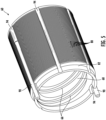
FIG. 5 is a perspective view of an inner nut portion of the nut ofFIG. 3 according to an embodiment. - With reference to
FIG. 1 , a schematic illustration of anaircraft 20 that may incorporate embodiment of the present disclosure is shown. The aircraft includes afuselage 22,wings 24, and atail 26. In the illustrated, non-limiting embodiment, theaircraft 20 includes wing-mountedaircraft power systems 28. The wing-mountedaircraft power systems 28 may be conventional gas turbine engines or other propulsion systems known in the art. In other configurations, aircraft employing embodiments of the present disclosure may include fuselage-mounted and/or tail-mounted configurations. Theaircraft power systems 28 may be used to generate thrust for flight and may also be used to generate onboard electrical power. Theaircraft 20 may also include one or moreauxiliary power units 30 that may be configured to generate power. Theaircraft 20 includesdoors 32 and aircraft flight control surfaces 34 (e.g., ailerons, flaps, flaperons, stabilizers, etc.). Additionally, theaircraft power systems 28 may includethrust reversers 36, as will be appreciated by those of skill in the art. - Control or actuation of various components of the
aircraft 20 may be enabled through the use of actuators. Actuators onboard aircraft can be used for, for example, actuating thedoors 32, theflight control surfaces 34, thethrust reversers 36, landing gear, interior doors, seats, and the like. The actuators may be configured as leadscrew and nut configurations. These actuators are typically linear actuators that rotate a nut to drive the leadscrew in an axial direction along an axis of the leadscrew or rotate screw to drive the nut in axial direction. - Referring now to
FIG. 2 , anactuator 50 that may incorporate embodiments of the present disclosure is illustrated.FIG. 2 shows part of anengine housing 40 including adoor 42, such as a cowl door for example, moveable between a closed position and an open position. InFIG. 2 , thedoor 42 is shown in its open position. Theactuator 50 is arranged to drive thedoor 42 between the closed position and the open position. In the example shown, theactuator 50 is in the form of a linear actuator including ahousing 52 that contains anut 54. Thenut 54 is rotatable within thehousing 52 and drives linear motion of ascrew 56, such as a ball screw for example. By rotating thenut 54, thescrew 56 will translate, such as extend and retracted, to drive thedoor 42 between the closed position and the open position. However, in other embodiments, thescrew 56 is rotatable in a fixed axial position such that thenut 54 will translate along the axis of thescrew 56 between an extended and retracted position. This type of actuation may be used for any controllable component onboard an aircraft, such as the various components described above and as appreciated by those of skill in the art. - With reference now to
FIG. 3-5 , an example of thenut 54 of theactuator 50 is illustrated in more detail. As shown, thenut 54 may be an assembly having aninner nut portion 60 and anouter nut portion 62 formed from different materials. In the illustrated, non-limiting embodiment, theinner nut portion 60 is formed from a compliant material, such as a polymer for example, and the outer nut portion is formed from a rigid material, such as a metal material. However, it should be understood that other suitable materials are also within the scope of the disclosure. Theinner nut portion 60, also referred to herein as a bush nut, may have a generallyannular body 64. Theinner nut portion 60 is movably coupled to therotatable screw 56. In the illustrated, non-limiting embodiment, theinner nut portion 60 includes a first plurality ofthreads 66 formed at aninterior surface 68 of thebody 64. The first plurality ofthreads 66 is complementary to and configured to rotatably engage the plurality ofthreads 70 formed about an exterior surface of thescrew 56. - The
outer nut portion 62, also referred to herein as a casing, may also have a generallyannular body 72. In an embodiment, an axial length of theouter nut portion 62 is greater than the axial length of theinner nut portion 60. However, embodiments where the inner andouter nut portions inner nut portion 60 has a greater length than theouter nut portion 62 are also within the scope of the disclosure. In an embodiment, at least oneflange 74 extends radially outward from anexterior surface 76 of theouter nut portion 62. As shown, theouter nut portion 62 may be arranged within asupport structure 100 of a movable component. Theflange 74 may be configured to abut or contact one or more adjacent protrusions orsurfaces 102 such that this engagement between theflange 74 and asurface 102 of thesupport structure 100 transfers axial movement of the nut to the movable component. - As shown in
FIG. 4 , one ormore grooves 77, such as semi-circular recesses for example, may be formed in theexterior surface 76 of theouter nut portion 62. In such embodiments, a plurality ofelongated recesses 104 may be formed at an inner surface of thesupport structure 100. A plurality of engagement members (not shown) are receivable within agroove 77 and a correspondingelongated recess 104, respectively. Such a connection restricts rotation of theouter nut portion 62 relative to thesupport structure 100 while allowing translation of theouter nut portion 62 relative to thesupport structure 100. The limited axial motion of theouter nut portion 62 allowable relative to thesupport structure 100 may be referred to as "lost motion." This clearance or lost motion gap defining the allowed lost motion movement is intended to accommodate movement resulting from vibration deflection that occurs when the movable component, such as a cowl door for example, is in a stowed state. Accordingly, translational motion of theouter nut portion 62 resulting from rotation of thescrew 56 does not cause a corresponding movement of thesupport structure 100 and movable component until after travelling the lost motion gap. - In other embodiments, the
flange 74 may be coupled directly or indirectly to a movable component. In such embodiments, the translational movement of thenut 54 resulting from rotation of thescrew 56 about an axis causes corresponding component connected to thenut 54, such as acowl door 42 of an engine for example, to move. - As shown in
FIG. 3 , theinner nut portion 60 is removably couplable to theouter nut portion 62. The inner diameter ofouter nut portion 62 may be generally equal to the outer diameter of theinner nut portion 60 such that theinner nut portion 60 is receivable within the hollow interior of theouter nut portion 62. In the illustrated, non-limiting embodiment, when the inner andouter nut portions outer nut portions - The inner and
outer nut portions threads 80 arranged at theexterior surface 82 of theinner nut portion 60 and a complementary second plurality ofthreads 84 formed at theinterior surface 86 of theouter nut portion 62. Accordingly, relative rotation of the inner andouter nut portions threads outer nut portions threads 66 arranged at theinterior surface 68 of theinner nut portion 60 may be significantly less than thethreads 80 arranged at theouter surface 82 thereof. Themicrothreads threads 66 may have a second threads per inch, substantially smaller than the first threads per inch. For example, the pitch of thethreads 66 may be less than about 20 threads per inch, and in some embodiments, less than 15 threads per inch, less than about 10 threads per inch, or less than about 5 threads per inch. As a result, the overall size of thethreads 80 is small compared to the size of thethreads 66. In an embodiment, the overall ratio of at least one of the first and second plurality ofthreads threads 66 may be greater than or equal to about 10:1, and in some embodiments, greater than or equal to about 11:1, 12:1, 13:1, 14:1, 15:1, 16:1, 17:1, 18:1, 19:1, and 20:1. - At least one
anti-rotation pin 90 may be arranged at the interface between theexterior surface 82 of theinner nut portion 60 and theinner surface 86 of theouter nut portion 62. As shown, at least one outer groove orslot 92 is formed in theinner surface 86 of theouter nut portion 62 and a corresponding inner groove orslot 94 is formed inouter surface 82 of theinner nut portion 60. The inner andouter grooves anti-rotation pin 90 therein, similar to a key and keyway. Accordingly, when the microthreads of the inner andouter nut portions outer grooves anti-rotation pin 90 is received therebetween to restrict relative rotation of the inner andouter nut portions - The number of
outer grooves 92 formed in theouter nut portion 62 may but need not be equal to the number ofinner grooves 94 formed in theinner nut portion 64. Having different numbers of inner andouter grooves inner nut portion 60 relative to theouter nut portion 62 while still engaging a minimum number of anti-rotation pins 90. For example, theouter nut portion 62 may include sixouter grooves 92 and theinner nut portion 60 may include fourinner grooves 94 will enable assembly of twoanti-rotation pins 90 with an angular mismatch of 15° of less between the outer andinner grooves anti-rotation pin 90. Although twoanti-rotation pins 90 are illustrated in the non-limiting embodiment, it should be appreciated that embodiments having one or more than two anti-rotation pins, such as three, four, or more than fouranti-rotation pins 90 are also within the scope of the disclosure. - During operation of the
actuator 50, the load acting on theflange 74 of theouter nut portion 62 is transferred to theinner nut portion 60 via themicrothreads inner nut portion 60 to thescrew 56 via thethreads inner nut portion 60 from a compliant material, the load applied thereto is distributed over the length of thethreads - A
nut 54 as described herein provides enhanced flexibility in transferring the load applied to the flange across the length of the nut, resulting in improved wear performance. In addition, by using a compliant material for theinner nut portion 60, the weight of the nut is reduced. - While the present disclosure has been described in detail in connection with only a limited number of embodiments, it should be readily understood that the present disclosure is not limited to such disclosed embodiments. Rather, the present disclosure can be modified to incorporate any number of variations, alterations, substitutions, or equivalent arrangements not heretofore described, but which are commensurate with the spirit and scope of the present disclosure. Additionally, while various embodiments of the present disclosure have been described, it is to be understood that aspects of the present disclosure may include only some of the described embodiments. Accordingly, the present disclosure is not to be seen as limited by the foregoing description but is only limited by the scope of the appended claims.
Claims (15)
- A nut for use in an actuator assembly having a rotatable screw, the nut comprising:an outer nut portion (62);an inner nut portion (60) removably coupled to the outer nut portion (62), the inner nut portion (60) being rotatably couplable to the rotatable screw; andat least one anti-rotation pin (90) positionable between the outer nut portion (62) and the inner nut portion (60) to restrict rotation of the inner nut portion (60) relative to the outer nut portion (62).
- The nut of claim 1, wherein the nut is fixedly mounted within the actuator assembly such that the rotatable screw is movable relative to the nut.
- The nut of claim 1 or 2, wherein the nut is translatable along an axis relative to the rotatable screw.
- The nut of any preceding claim, wherein the outer nut portion (62) has a flange arranged at an exterior surface thereof, the flange being connectable to a component to be moved by the actuator assembly.
- The nut of any preceding claim, wherein the outer nut portion (62) and the inner nut portion (60) are formed different materials.
- The nut of claim 5, wherein the inner nut portion (60) is formed from a polymer, and/or wherein the outer nut portion (62) is formed from a metal.
- The nut of any preceding claim, further comprising a first plurality of threads arranged at an outer surface of the inner nut portion (60) and a second plurality of threads arranged at an inner surface of the outer nut portion (62).
- The nut of claim 7, wherein the first plurality of threads and the second plurality of threads are microthreads.
- The nut of any preceding claim, further comprising a plurality of threads arranged at an inner surface of the inner nut portion (60), the plurality of threads being couplable to the rotatable screw, and optionally further comprising another plurality of threads arranged at an outer surface of the inner nut portion (60), wherein the plurality of threads has a first threads per inch and the another plurality of threads has a second threads per inch, the second threads per inch being greater than the first threads per inch.
- An actuator assembly for controlling movement of an aircraft engine door comprising:a screw rotatable about an axis;a nut rotatably engaged with the screw, the nut further comprising:an outer nut portion (62); andan inner nut portion (60) removably coupled to the outer nut portion (62), the inner nut portion (60) being rotatably fixed to the outer nut portion (62).
- The system of claim 10, wherein the nut further comprises at least one anti-rotation pin (90) positioned between the outer nut portion (62) and the inner nut portion (60) to restrict rotation of the inner nut portion (60) relative to the outer nut portion (62).
- The system of claim 10 or 11, wherein the outer nut portion (62) and the inner nut portion (60) are formed different materials, and optionally wherein the inner nut portion (60) is formed from a polymer, and/or wherein the outer nut portion (62) is formed from a metal.
- The system of any of claims 10 to 12, further comprising a plurality of threads arranged at an inner surface of the inner nut portion (60), the plurality of threads being couplable the screw.
- The system of any of claims 10 to 13, further comprising a first plurality of threads arranged at an outer surface of the inner nut portion (60) and a second plurality of threads arranged at an inner surface of the outer nut portion (62), and optionally wherein the first plurality of threads and the second plurality of threads are microthreads.
- The system of claim 12, wherein the nut is coupled to a cowl door, the actuator assembly being operable to move the aircraft engine door between an open position and a closed position.
Applications Claiming Priority (1)
| Application Number | Priority Date | Filing Date | Title |
|---|---|---|---|
| IN202311047163 | 2023-07-13 |
Publications (1)
| Publication Number | Publication Date |
|---|---|
| EP4491907A1 true EP4491907A1 (en) | 2025-01-15 |
Family
ID=91898847
Family Applications (1)
| Application Number | Title | Priority Date | Filing Date |
|---|---|---|---|
| EP24187703.4A Pending EP4491907A1 (en) | 2023-07-13 | 2024-07-10 | Nut for actuator system and actuator system comprising the same |
Country Status (3)
| Country | Link |
|---|---|
| US (1) | US20250020156A1 (en) |
| EP (1) | EP4491907A1 (en) |
| CA (1) | CA3244853A1 (en) |
Citations (4)
| Publication number | Priority date | Publication date | Assignee | Title |
|---|---|---|---|---|
| CN201772035U (en) * | 2010-07-16 | 2011-03-23 | 浙江新益控制系统有限公司 | A drive nut for a linear drive |
| US20130160586A1 (en) * | 2011-04-15 | 2013-06-27 | Ball Screws And Actuators Co. | Self lubricating linear motion guided screw assembly |
| CN112923035A (en) * | 2021-01-29 | 2021-06-08 | 义乌市长新传动科技有限公司 | Novel transmission nut |
| US20230078972A1 (en) * | 2021-09-16 | 2023-03-16 | Hamilton Sundstrand Corporation | Drive-through friction clutch as a tensile load disconnect |
Family Cites Families (4)
| Publication number | Priority date | Publication date | Assignee | Title |
|---|---|---|---|---|
| US3516696A (en) * | 1968-08-21 | 1970-06-23 | Amsted Ind Inc | Slack adjuster |
| US7992456B2 (en) * | 2007-12-10 | 2011-08-09 | Pacific Bearing Company | Anti-backlash nut, lead screw assembly and method |
| US11236778B2 (en) * | 2019-03-12 | 2022-02-01 | Earl Allen Size, JR. | Multi-piece anti-vibration locking fastener having coaxially arranged inner and outer opposite threaded bolts in combination with successive and opposite threaded profiles within a thickened base layer |
| US11821498B2 (en) * | 2021-09-28 | 2023-11-21 | Hamilton Sundstrand Corporation | Polymeric thread insert for high load leadscrew and nut |
-
2023
- 2023-10-27 US US18/496,422 patent/US20250020156A1/en active Pending
-
2024
- 2024-06-28 CA CA3244853A patent/CA3244853A1/en active Pending
- 2024-07-10 EP EP24187703.4A patent/EP4491907A1/en active Pending
Patent Citations (4)
| Publication number | Priority date | Publication date | Assignee | Title |
|---|---|---|---|---|
| CN201772035U (en) * | 2010-07-16 | 2011-03-23 | 浙江新益控制系统有限公司 | A drive nut for a linear drive |
| US20130160586A1 (en) * | 2011-04-15 | 2013-06-27 | Ball Screws And Actuators Co. | Self lubricating linear motion guided screw assembly |
| CN112923035A (en) * | 2021-01-29 | 2021-06-08 | 义乌市长新传动科技有限公司 | Novel transmission nut |
| US20230078972A1 (en) * | 2021-09-16 | 2023-03-16 | Hamilton Sundstrand Corporation | Drive-through friction clutch as a tensile load disconnect |
Also Published As
| Publication number | Publication date |
|---|---|
| CA3244853A1 (en) | 2025-06-06 |
| US20250020156A1 (en) | 2025-01-16 |
Similar Documents
| Publication | Publication Date | Title |
|---|---|---|
| US5092539A (en) | Jam resistant ball screw actuator | |
| US11181073B2 (en) | Actuator equipped with a no back system with inhibition zone | |
| CA2657474C (en) | Flap actuator | |
| EP1832509B1 (en) | Controlled propeller pitch lock actuation system | |
| US9086035B2 (en) | Integrated thrust reverser actuator and variable area fan nozzle actuator | |
| US10605199B2 (en) | Cylinder with integrated locking | |
| US20170335932A1 (en) | Hydraulic rotary ball screw actuator | |
| US10724477B2 (en) | Tertiary lock system for a thrust reverser | |
| US20050001095A1 (en) | Self-aligning thrust reverser system lock assembly | |
| EP3931434B1 (en) | Traveling finger lock for an actuator | |
| EP3480116B1 (en) | Electro-mechanical actuator systems for opening and closing of aircraft engine cowl doors | |
| EP4155581B1 (en) | Polymeric thread insert for high load leadscrew and nut | |
| EP1288478B1 (en) | Synchronization cross-feed system | |
| US20250020156A1 (en) | Nut design for actuator system | |
| US11788490B1 (en) | Traveling finger lock for an actuator | |
| US11555470B2 (en) | Multiple piece piston | |
| BR102024014184A2 (en) | NUT FOR USE IN AN ACTUATOR ASSEMBLY WITH A ROTARY SCREW, AND, ACTUATOR ASSEMBLY FOR CONTROLLING THE MOVEMENT OF AN AIRCRAFT ENGINE DOOR | |
| EP3489547B1 (en) | Thrust reverser with motion control device | |
| CA3187078A1 (en) | Actuator overtravel stop assembly |
Legal Events
| Date | Code | Title | Description |
|---|---|---|---|
| PUAI | Public reference made under article 153(3) epc to a published international application that has entered the european phase |
Free format text: ORIGINAL CODE: 0009012 |
|
| STAA | Information on the status of an ep patent application or granted ep patent |
Free format text: STATUS: THE APPLICATION HAS BEEN PUBLISHED |
|
| AK | Designated contracting states |
Kind code of ref document: A1 Designated state(s): AL AT BE BG CH CY CZ DE DK EE ES FI FR GB GR HR HU IE IS IT LI LT LU LV MC ME MK MT NL NO PL PT RO RS SE SI SK SM TR |
|
| STAA | Information on the status of an ep patent application or granted ep patent |
Free format text: STATUS: REQUEST FOR EXAMINATION WAS MADE |
|
| 17P | Request for examination filed |
Effective date: 20250714 |
|
| STAA | Information on the status of an ep patent application or granted ep patent |
Free format text: STATUS: EXAMINATION IS IN PROGRESS |
|
| 17Q | First examination report despatched |
Effective date: 20260305 |