EP4491882A1 - Pump with reduced noise emission - Google Patents
Pump with reduced noise emission Download PDFInfo
- Publication number
- EP4491882A1 EP4491882A1 EP24187588.9A EP24187588A EP4491882A1 EP 4491882 A1 EP4491882 A1 EP 4491882A1 EP 24187588 A EP24187588 A EP 24187588A EP 4491882 A1 EP4491882 A1 EP 4491882A1
- Authority
- EP
- European Patent Office
- Prior art keywords
- pump
- sound shield
- sound
- centrifugal pump
- shield
- Prior art date
- Legal status (The legal status is an assumption and is not a legal conclusion. Google has not performed a legal analysis and makes no representation as to the accuracy of the status listed.)
- Pending
Links
Images



Classifications
-
- F—MECHANICAL ENGINEERING; LIGHTING; HEATING; WEAPONS; BLASTING
- F04—POSITIVE - DISPLACEMENT MACHINES FOR LIQUIDS; PUMPS FOR LIQUIDS OR ELASTIC FLUIDS
- F04B—POSITIVE-DISPLACEMENT MACHINES FOR LIQUIDS; PUMPS
- F04B53/00—Component parts, details or accessories not provided for in, or of interest apart from, groups F04B1/00 - F04B23/00 or F04B39/00 - F04B47/00
- F04B53/16—Casings; Cylinders; Cylinder liners or heads; Fluid connections
-
- F—MECHANICAL ENGINEERING; LIGHTING; HEATING; WEAPONS; BLASTING
- F04—POSITIVE - DISPLACEMENT MACHINES FOR LIQUIDS; PUMPS FOR LIQUIDS OR ELASTIC FLUIDS
- F04B—POSITIVE-DISPLACEMENT MACHINES FOR LIQUIDS; PUMPS
- F04B53/00—Component parts, details or accessories not provided for in, or of interest apart from, groups F04B1/00 - F04B23/00 or F04B39/00 - F04B47/00
- F04B53/001—Noise damping
-
- F—MECHANICAL ENGINEERING; LIGHTING; HEATING; WEAPONS; BLASTING
- F04—POSITIVE - DISPLACEMENT MACHINES FOR LIQUIDS; PUMPS FOR LIQUIDS OR ELASTIC FLUIDS
- F04B—POSITIVE-DISPLACEMENT MACHINES FOR LIQUIDS; PUMPS
- F04B53/00—Component parts, details or accessories not provided for in, or of interest apart from, groups F04B1/00 - F04B23/00 or F04B39/00 - F04B47/00
- F04B53/001—Noise damping
- F04B53/002—Noise damping by encapsulation
-
- F—MECHANICAL ENGINEERING; LIGHTING; HEATING; WEAPONS; BLASTING
- F04—POSITIVE - DISPLACEMENT MACHINES FOR LIQUIDS; PUMPS FOR LIQUIDS OR ELASTIC FLUIDS
- F04D—NON-POSITIVE-DISPLACEMENT PUMPS
- F04D29/00—Details, component parts, or accessories
- F04D29/02—Selection of particular materials
- F04D29/026—Selection of particular materials especially adapted for liquid pumps
-
- F—MECHANICAL ENGINEERING; LIGHTING; HEATING; WEAPONS; BLASTING
- F04—POSITIVE - DISPLACEMENT MACHINES FOR LIQUIDS; PUMPS FOR LIQUIDS OR ELASTIC FLUIDS
- F04D—NON-POSITIVE-DISPLACEMENT PUMPS
- F04D29/00—Details, component parts, or accessories
- F04D29/40—Casings; Connections of working fluid
- F04D29/42—Casings; Connections of working fluid for radial or helico-centrifugal pumps
- F04D29/426—Casings; Connections of working fluid for radial or helico-centrifugal pumps especially adapted for liquid pumps
-
- F—MECHANICAL ENGINEERING; LIGHTING; HEATING; WEAPONS; BLASTING
- F04—POSITIVE - DISPLACEMENT MACHINES FOR LIQUIDS; PUMPS FOR LIQUIDS OR ELASTIC FLUIDS
- F04D—NON-POSITIVE-DISPLACEMENT PUMPS
- F04D29/00—Details, component parts, or accessories
- F04D29/66—Combating cavitation, whirls, noise, vibration or the like; Balancing
- F04D29/669—Combating cavitation, whirls, noise, vibration or the like; Balancing especially adapted for liquid pumps
-
- F—MECHANICAL ENGINEERING; LIGHTING; HEATING; WEAPONS; BLASTING
- F05—INDEXING SCHEMES RELATING TO ENGINES OR PUMPS IN VARIOUS SUBCLASSES OF CLASSES F01-F04
- F05D—INDEXING SCHEME FOR ASPECTS RELATING TO NON-POSITIVE-DISPLACEMENT MACHINES OR ENGINES, GAS-TURBINES OR JET-PROPULSION PLANTS
- F05D2260/00—Function
- F05D2260/96—Preventing, counteracting or reducing vibration or noise
-
- F—MECHANICAL ENGINEERING; LIGHTING; HEATING; WEAPONS; BLASTING
- F05—INDEXING SCHEMES RELATING TO ENGINES OR PUMPS IN VARIOUS SUBCLASSES OF CLASSES F01-F04
- F05D—INDEXING SCHEME FOR ASPECTS RELATING TO NON-POSITIVE-DISPLACEMENT MACHINES OR ENGINES, GAS-TURBINES OR JET-PROPULSION PLANTS
- F05D2300/00—Materials; Properties thereof
- F05D2300/40—Organic materials
- F05D2300/43—Synthetic polymers, e.g. plastics; Rubber
Definitions
- the invention relates to a pump, such as a booster pump or a circulator pump, which generates less noise during operation.
- a housing of the pump can even increase this noise, because it also starts to vibrate and acts effectively like a loudspeaker.
- a conventional booster pump for increasing water pressure can generate noise above 55 dB(A) during operation.
- Such a noise level can be perceived as disruptive and can make it difficult to work in the vicinity of the pump for long periods of time.
- the invention relates to a pump, comprising: a pump casing which comprises a casing section which is made of a first material, and a sound shield which is made of a second material; wherein the second material has higher sound dampening properties than the first material.
- the sound shield can cover the parts of the pump which generate most of the noise, for instance, the water carrying parts of the pump and/or the pump head.
- the sound shield can form a second casing section made from the second material.
- the sound shield can be a sound dampening element.
- the second material having higher sound dampening properties than the first material means that a component which is made of the second material (such as the sound shield) is less permeable to noise compared to a component which is made of the first material (such as the casing section). This can be due to an enhanced absorption of noise by the second material compared to the first material.
- the pump can be a booster pump, a circulator pump, a jet pump or a different type of pump for pumping fluids.
- the pump can be a centrifugal pump.
- the pump can comprise a rotating impeller to transport the fluid (e.g., water).
- the second material is a thermoplastic elastomer (TPE).
- TPE thermoplastic elastomer
- TPU thermoplastic polyurethane
- the first material can be a plastic, such as polycarbonate (PC), or a composite material, e.g. a composite plastic.
- the first material can be a polymer composite.
- the first material could also be a metal, such as cast iron or aluminum.
- the sound shield is made from one part.
- the sound shield is fabricated by injection molding.
- the sound shield is non-planar shaped.
- the sound shield has a three-dimensional and/or warped shape.
- the sound shield is arranged to cover at least one side of the pump, preferably multiple sides of the pump, at least partially.
- the sound shield and the casing section are arranged to cover different sections of the pump.
- the sound shield is arranged above the casing section.
- the sound shield can surround and/or cover at least a part of the casing section.
- the sound shield is arranged to at least partially cover a pump motor and/or a fluid carrying element of the pump.
- the sound shield is arranged to cover one or more hydraulic components of the pump, i.e., components which have fluid (e.g., water) flowing through them.
- the sound shield can block hydraulic noise (which stems from the fluids and/or from pump components which move the fluid). If the sound shield additionally covers the motor, it can block motor generated noise.
- the sound shield comprises at least one opening, wherein an inlet and/or outlet of the pump extend(s) through the at least one opening.
- the sound shield is not in contact with a fluid to be pumped.
- the pump shield may not be part of a fluid enclosure of the pump.
- the sound shield can be arranged above the fluid enclosure, e.g. at least partially covering the fluid enclosure.
- the sound shield is removably attached to the casing section and/or to the pump.
- the sound shield can be attached to the casing section at the rim.
- the pump is fully operative if the sound shield is removed.
- the sound shield reduces a noise level of the pump by at least 3 dB(A), preferably by at least 5 dB(A), when mounted to the pump.
- the invention relates to a use of a sound shield for absorbing noise in a pump according to the first aspect of the invention.
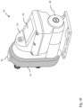
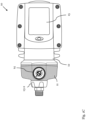
- Figs. 1A-C show different views of a pump 10 according to an embodiment.
- the pump 10 has a pump casing which comprises a casing section 12 made of a first material, and a sound shield 11 made of a second material; wherein the second material has higher sound dampening properties than the first material.
- the exemplary pump 10 shown in Figs. 1A-C is a booster pump.
- a casing which comprises the casing section 12 and the sound shield 11, can be used in different types of pumps, e.g. in circulatory pumps or in jet pumps (as shown in Figs. 2A-B and 3 ).
- the pump 10 is a centrifugal pump for pumping water.
- the first material is a plastic material, such as polycarbonate (PC).
- the first material can also be a composite plastic, e.g. a polymer composite.
- the first material could be a metal, such as cast iron or aluminum.
- the casing section 12 which is made of the first material, can comprise different sub-sections or casing parts which cover different components of the pump.
- the casing section 12 can comprise an electronics housing/box and/or a stator housing.
- the second material can be a thermoplastic elastomer (TPE) material, in particular thermoplastic polyurethane (TPU).
- TPE thermoplastic elastomer
- TPU thermoplastic polyurethane
- this material is relatively soft (e.g., softer than the first material) which results in improved vibration absorbing properties and, thus, sound dampening.
- TPU has a relatively high mass which further enhances its sound dampening properties.
- the sound shield 11 (highlighted in gray in Figs. 1A-C ) can have a non-planar shape, in particular a warped and/or 3D shape.
- the sound shield 11 can cover at least one side of the pump 10, preferably multiple sides of the pump 10, at least partially.
- the sound shield 11 can further be made from one part and/or can be free standing. This can enhance its stability and further improve its sound-dampening properties.
- the sound shield 11 is fabricated as a one-piece component from a TPE material (e.g., TPU) via injection molding.
- a TPE material e.g., TPU
- the sound shield 11 and the casing section 12 can cover different sections of the pump.
- the sound shield 11 and the casing section 12 can be in contact which each other, e.g. at their respective rims where they are mounted to each other and/or to other (internal) pump components.
- the sound shield 11 is in close proximity to at least one element of the pump 10 which is a source of noise during operation of the pump 10.
- this element can be a hydraulic part (i.e., a part through which the fluid flows).
- the sound shield 11 can block hydraulic noise caused by the movement of fluids through the pump.
- the sound shield 11 can form a cover for the hydraulic components of the pump 10.
- the pump casing 12 can form a cover for the pump motor.
- the sound shield 11 may also be arranged to cover the motor of the pump.
- the casing can be an external cover or a housing of the pump 10.
- the casing, especially the sound shield 11 is not in contact with a fluid (e.g., water) to be pumped.
- the pump 10 can have one or more fluid enclosures which are covered by the casing and, in particular, by the sound shield 11.
- the sound shield 11 can comprise a number of openings to allow access to internal components of the pump, e.g. to the fluid enclosure, and/or to allow connecting external elements, such as hoses or tubes.
- a pump inlet 13-1 and a pump outlet 13-2 can be arranged to pass through two respective openings in the sound shield 11, as shown in Figs. 1A-C . Further openings in the sound shield 11 can be arranged for mounting a valve 14 in the internal fluid enclosure of the pump 10 and/or a drain plug 17.
- the casing section 12 may comprise or accommodate further optional elements, such as an interface 15 and a plug 16 for accessing a pump shaft.
- the sound shield 11 can further be mounted removably and/or replaceably to the casing section 12 and/or to the pump 10. Thereby, the pump 10 can stay fully operative if the sound shield 11 is removed.
- the sound shield 11 reduces a noise level of the pump 10 by at least 3 dB(A), preferably by at least 5 dB(A), when mounted to the pump 10, e.g. from ca. 50 dB(A) to ca. 45 dB(A).
- the sound shield 11 reduces the sound energy, which is emitted by the pump, by at least half.
- the sound shield 11 reduces the noise level of the pump 10 by at least 3 dB(A), preferably by at least 5 dB(A), compared to a pump where the entire casing is made from the first material (e.g., where a further casing section made from the first material is mounted in place of the sound shield 11).
- Figs. 2A-B show schematic diagrams of pumps 10 according to an embodiment.
- the pumps 10 shown in Figs. 2A and 2B are circulator pumps.
- the sound shield 11 is arranged to cover at least a part of a pump motor and/or pump electronics.
- the sound shield 11 can cover a control box of the pump 10 which is mounted on top of and around a pump head (which includes the motor).
- the sound shield 11 can thereby reduce noised generated by vibrations from the pump head. In this way, noise generated from the motor in the pump head can be efficiently reduced.
- the casing of these pumps can comprise additional casing sections 12, 21 made from different materials.
- a casing section 12 which also covers a part of the pump electronics can be made from polycarbonate (PC) and a further casing section 21, which carries the fluid, can be made from cast iron.
- Figs. 3 shows a schematic diagram of a pump 10 according to an embodiment.
- the pump 10 shown in Fig. 3 is a jet pump.
- the sound shield 11 (indicated by a dashed line) is arranged on top of at least a part of the casing section 12, i.e., it covers and/or surrounds at least a part of the casing section 12.
- the casing section 12 is thereby, for instance, made of a polymer composite.
- the sound shield 11 can comprise several openings to connect further components to the casing section 12 and/or to a fluid carrying element below, for instance, a pressure control unit 32.
- the pump motor can be covered by a further casing section 31, which can be made from the same material as the casing section 12.
Landscapes
- Engineering & Computer Science (AREA)
- Mechanical Engineering (AREA)
- General Engineering & Computer Science (AREA)
- Structures Of Non-Positive Displacement Pumps (AREA)
Abstract
The invention relates to a pump (10) which comprises a pump casing. The pump casing comprises a casing section (12) which is made of a first material, and a sound shield (11) which is made of a second material; wherein the second material has higher sound dampening properties than the first material.
Description
- The invention relates to a pump, such as a booster pump or a circulator pump, which generates less noise during operation.
- Many pumps generate a significant amount of noise when being operated due to vibrations of hydraulic components or of the pump motor. Thereby, a housing of the pump can even increase this noise, because it also starts to vibrate and acts effectively like a loudspeaker. For instance, a conventional booster pump for increasing water pressure can generate noise above 55 dB(A) during operation.
- Such a noise level can be perceived as disruptive and can make it difficult to work in the vicinity of the pump for long periods of time.
- Thus, it is an objective to reduce the noise generated by a pump during operation.
- The object of the present invention is achieved by the solution provided in the enclosed independent claims. Advantageous implementations of the present invention are further defined in the dependent claims.
- According to a first aspect, the invention relates to a pump, comprising: a pump casing which comprises a casing section which is made of a first material, and a sound shield which is made of a second material; wherein the second material has higher sound dampening properties than the first material.
- This achieves the advantage that the pump emits less noise during operation. The sound shield can cover the parts of the pump which generate most of the noise, for instance, the water carrying parts of the pump and/or the pump head.
- The sound shield can form a second casing section made from the second material. The sound shield can be a sound dampening element.
- In particular, the second material having higher sound dampening properties than the first material means that a component which is made of the second material (such as the sound shield) is less permeable to noise compared to a component which is made of the first material (such as the casing section). This can be due to an enhanced absorption of noise by the second material compared to the first material.
- The pump can be a booster pump, a circulator pump, a jet pump or a different type of pump for pumping fluids.
- The pump can be a centrifugal pump. For instance, the pump can comprise a rotating impeller to transport the fluid (e.g., water).
- In an embodiment, the second material is a thermoplastic elastomer (TPE). For example, the second material is thermoplastic polyurethane (TPU).
- The first material can be a plastic, such as polycarbonate (PC), or a composite material, e.g. a composite plastic. For instance, the first material can be a polymer composite. Alternatively, the first material could also be a metal, such as cast iron or aluminum.
- In an embodiment, the sound shield is made from one part.
- For example, the sound shield is fabricated by injection molding.
- In an embodiment, the sound shield is non-planar shaped.
- For instance, the sound shield has a three-dimensional and/or warped shape.
- In an embodiment, the sound shield is arranged to cover at least one side of the pump, preferably multiple sides of the pump, at least partially.
- In an embodiment, the sound shield and the casing section are arranged to cover different sections of the pump.
- In an embodiment, the sound shield is arranged above the casing section. For example, the sound shield can surround and/or cover at least a part of the casing section.
- In an embodiment, the sound shield is arranged to at least partially cover a pump motor and/or a fluid carrying element of the pump.
- For instance, the sound shield is arranged to cover one or more hydraulic components of the pump, i.e., components which have fluid (e.g., water) flowing through them. In this way, the sound shield can block hydraulic noise (which stems from the fluids and/or from pump components which move the fluid). If the sound shield additionally covers the motor, it can block motor generated noise.
- In an embodiment, the sound shield comprises at least one opening, wherein an inlet and/or outlet of the pump extend(s) through the at least one opening.
- In an embodiment, the sound shield is not in contact with a fluid to be pumped.
- In other words, the pump shield may not be part of a fluid enclosure of the pump. However, the sound shield can be arranged above the fluid enclosure, e.g. at least partially covering the fluid enclosure.
- In an embodiment, the sound shield is removably attached to the casing section and/or to the pump.
- For example, the sound shield can be attached to the casing section at the rim.
- In an embodiment, the pump is fully operative if the sound shield is removed.
- In an embodiment, the sound shield reduces a noise level of the pump by at least 3 dB(A), preferably by at least 5 dB(A), when mounted to the pump.
- According to a second aspect, the invention relates to a use of a sound shield for absorbing noise in a pump according to the first aspect of the invention.
- The invention will be explained in the following together with the figures.
- Figs. 1A-C
- shows different views of a pump according to an embodiment;
- Figs. 2A-B
- show schematic diagrams of pumps according to an embodiment; and
- Fig. 3
- shows a schematic diagram of a pump according to an embodiment.
-
Figs. 1A-C show different views of apump 10 according to an embodiment. - The
pump 10 has a pump casing which comprises acasing section 12 made of a first material, and asound shield 11 made of a second material; wherein the second material has higher sound dampening properties than the first material. - The
exemplary pump 10 shown inFigs. 1A-C is a booster pump. However, such a casing, which comprises thecasing section 12 and thesound shield 11, can be used in different types of pumps, e.g. in circulatory pumps or in jet pumps (as shown inFigs. 2A-B and3 ). - For example, the
pump 10 is a centrifugal pump for pumping water. - For instance, the first material is a plastic material, such as polycarbonate (PC). The first material can also be a composite plastic, e.g. a polymer composite. Alternatively, the first material could be a metal, such as cast iron or aluminum.
- The
casing section 12, which is made of the first material, can comprise different sub-sections or casing parts which cover different components of the pump. For example, thecasing section 12 can comprise an electronics housing/box and/or a stator housing. - The second material can be a thermoplastic elastomer (TPE) material, in particular thermoplastic polyurethane (TPU). For instance, this material is relatively soft (e.g., softer than the first material) which results in improved vibration absorbing properties and, thus, sound dampening. At the same time, TPU has a relatively high mass which further enhances its sound dampening properties.
- The sound shield 11 (highlighted in gray in
Figs. 1A-C ) can have a non-planar shape, in particular a warped and/or 3D shape. When mounted to thepump 10, thesound shield 11 can cover at least one side of thepump 10, preferably multiple sides of thepump 10, at least partially. - The
sound shield 11 can further be made from one part and/or can be free standing. This can enhance its stability and further improve its sound-dampening properties. - For instance, the
sound shield 11 is fabricated as a one-piece component from a TPE material (e.g., TPU) via injection molding. - As shown for the
exemplary pump 10 inFigs. 1A-C , thesound shield 11 and thecasing section 12 can cover different sections of the pump. However, thesound shield 11 and thecasing section 12 can be in contact which each other, e.g. at their respective rims where they are mounted to each other and/or to other (internal) pump components. - Preferably, the
sound shield 11 is in close proximity to at least one element of thepump 10 which is a source of noise during operation of thepump 10. For instance, this element can be a hydraulic part (i.e., a part through which the fluid flows). In this way, thesound shield 11 can block hydraulic noise caused by the movement of fluids through the pump. Thus, thesound shield 11 can form a cover for the hydraulic components of thepump 10. In contrast, thepump casing 12 can form a cover for the pump motor. - The
sound shield 11 may also be arranged to cover the motor of the pump. - The casing can be an external cover or a housing of the
pump 10. For instance, the casing, especially thesound shield 11, is not in contact with a fluid (e.g., water) to be pumped. Thepump 10 can have one or more fluid enclosures which are covered by the casing and, in particular, by thesound shield 11. - The
sound shield 11 can comprise a number of openings to allow access to internal components of the pump, e.g. to the fluid enclosure, and/or to allow connecting external elements, such as hoses or tubes. - For instance, a pump inlet 13-1 and a pump outlet 13-2 can be arranged to pass through two respective openings in the
sound shield 11, as shown inFigs. 1A-C . Further openings in thesound shield 11 can be arranged for mounting avalve 14 in the internal fluid enclosure of thepump 10 and/or adrain plug 17. - Also, the
casing section 12 may comprise or accommodate further optional elements, such as aninterface 15 and aplug 16 for accessing a pump shaft. - The
sound shield 11 can further be mounted removably and/or replaceably to thecasing section 12 and/or to thepump 10. Thereby, thepump 10 can stay fully operative if thesound shield 11 is removed. - For instance, the
sound shield 11 reduces a noise level of thepump 10 by at least 3 dB(A), preferably by at least 5 dB(A), when mounted to thepump 10, e.g. from ca. 50 dB(A) to ca. 45 dB(A). For example, thesound shield 11 reduces the sound energy, which is emitted by the pump, by at least half. - In particular, the
sound shield 11 reduces the noise level of thepump 10 by at least 3 dB(A), preferably by at least 5 dB(A), compared to a pump where the entire casing is made from the first material (e.g., where a further casing section made from the first material is mounted in place of the sound shield 11). -
Figs. 2A-B show schematic diagrams ofpumps 10 according to an embodiment. For instance, thepumps 10 shown inFigs. 2A and 2B are circulator pumps. - In the example shown in
Figs. 2A-B , thesound shield 11 is arranged to cover at least a part of a pump motor and/or pump electronics. - For instance, the
sound shield 11 can cover a control box of thepump 10 which is mounted on top of and around a pump head (which includes the motor). Thesound shield 11 can thereby reduce noised generated by vibrations from the pump head. In this way, noise generated from the motor in the pump head can be efficiently reduced. - Besides the
sound shield 11, the casing of these pumps can compriseadditional casing sections casing section 12 which also covers a part of the pump electronics can be made from polycarbonate (PC) and afurther casing section 21, which carries the fluid, can be made from cast iron. -
Figs. 3 shows a schematic diagram of apump 10 according to an embodiment. For instance, thepump 10 shown inFig. 3 is a jet pump. - In the exemplary pump shown in
Fig. 3 , the sound shield 11 (indicated by a dashed line) is arranged on top of at least a part of thecasing section 12, i.e., it covers and/or surrounds at least a part of thecasing section 12. Thecasing section 12 is thereby, for instance, made of a polymer composite. - The
sound shield 11 can comprise several openings to connect further components to thecasing section 12 and/or to a fluid carrying element below, for instance, apressure control unit 32. - The pump motor can be covered by a
further casing section 31, which can be made from the same material as thecasing section 12. - It is to be noted that the respective arrangements of the casing and, in particular, of the
sound shield 11 in the exemplary pumps ofFigs. 1A-C ,2A-B and3 is not limited to the shown pump types, but can be implemented for other pumps and pump types as well.
Claims (13)
- A centrifugal pump (10) for pumping water, comprising:a pump casing which comprises:- a casing section (12) which is made of a first material, and- a sound shield (11) which is made of a second material;wherein the second material has higher sound dampening properties than the first material;wherein the sound shield (11) is arranged to at least partially cover a water carrying element of the pump (10); andwherein the sound shield (11) is made from one part.
- The centrifugal pump (10) of claim 1,
wherein the second material is a thermoplastic elastomer. - The centrifugal pump (10) of any one of the preceding claims,
wherein the sound shield (11) is non-planar shaped. - The centrifugal pump (10) of any one of the preceding claims,
wherein the sound shield (11) is arranged to cover at least one side of the pump (10), preferably to cover multiple sides of the pump (10), at least partially. - The centrifugal pump (10) of any one of the preceding claims,
wherein the sound shield (11) and the casing section (12) are arranged to cover different sections of the pump (10). - The centrifugal pump (10) of any one of claims 1 to 4,
wherein the sound shield (11) is arranged above the casing section (12). - The centrifugal pump (10) of any one of the preceding claims,
wherein the sound shield (11) is further arranged to at least partially cover a pump motor. - The centrifugal pump (10) of any one of the preceding claims,
wherein the sound shield (11) comprises at least one opening, wherein an inlet (13-1) and/or outlet (13-2) of the pump (10) extend(s) through the at least one opening. - The centrifugal pump (10) of any one of the preceding claims,
wherein the sound shield (11) is not in contact with the water to be pumped. - The centrifugal pump (10) of any one of the preceding claims,
wherein the sound shield (11) is removably attached to the casing section (12) and/or to the pump (10). - The centrifugal pump (10) of any one of the preceding claims,
wherein the centrifugal pump (10) is fully operative if the sound shield (11) is removed. - The centrifugal pump (10) of any one of the preceding claims,
wherein the sound shield (11) reduces a noise level of the pump (10) by at least 3 dB(A) , preferably by at least 5 dB(A), when mounted to the pump (10). - Use of a sound shield (11) for absorbing noise in a centrifugal pump (10) of any one of the preceding claims.
Applications Claiming Priority (1)
| Application Number | Priority Date | Filing Date | Title |
|---|---|---|---|
| DKPA202370374 | 2023-07-10 |
Publications (1)
| Publication Number | Publication Date |
|---|---|
| EP4491882A1 true EP4491882A1 (en) | 2025-01-15 |
Family
ID=91899033
Family Applications (1)
| Application Number | Title | Priority Date | Filing Date |
|---|---|---|---|
| EP24187588.9A Pending EP4491882A1 (en) | 2023-07-10 | 2024-07-10 | Pump with reduced noise emission |
Country Status (2)
| Country | Link |
|---|---|
| EP (1) | EP4491882A1 (en) |
| CN (1) | CN119288851A (en) |
Citations (4)
| Publication number | Priority date | Publication date | Assignee | Title |
|---|---|---|---|---|
| DE3109624A1 (en) * | 1981-03-13 | 1982-10-14 | Wilo-Werk Gmbh & Co Pumpen- Und Apparatebau, 4600 Dortmund | Circulation pump |
| EP0516926A1 (en) * | 1991-06-01 | 1992-12-09 | WILO GmbH | Packaging of a pump |
| CN204692186U (en) * | 2015-05-27 | 2015-10-07 | 江门市地尔汉宇电器股份有限公司 | A kind ofly reduce noise and prevent the water pump cover that leaks and water pump |
| CN111237257A (en) * | 2018-11-28 | 2020-06-05 | 宁波海大嘉华汽车零部件制造有限公司 | Anti-drop automobile water pump |
-
2024
- 2024-07-10 CN CN202410923000.2A patent/CN119288851A/en active Pending
- 2024-07-10 EP EP24187588.9A patent/EP4491882A1/en active Pending
Patent Citations (4)
| Publication number | Priority date | Publication date | Assignee | Title |
|---|---|---|---|---|
| DE3109624A1 (en) * | 1981-03-13 | 1982-10-14 | Wilo-Werk Gmbh & Co Pumpen- Und Apparatebau, 4600 Dortmund | Circulation pump |
| EP0516926A1 (en) * | 1991-06-01 | 1992-12-09 | WILO GmbH | Packaging of a pump |
| CN204692186U (en) * | 2015-05-27 | 2015-10-07 | 江门市地尔汉宇电器股份有限公司 | A kind ofly reduce noise and prevent the water pump cover that leaks and water pump |
| CN111237257A (en) * | 2018-11-28 | 2020-06-05 | 宁波海大嘉华汽车零部件制造有限公司 | Anti-drop automobile water pump |
Also Published As
| Publication number | Publication date |
|---|---|
| CN119288851A (en) | 2025-01-10 |
Similar Documents
| Publication | Publication Date | Title |
|---|---|---|
| JP5581061B2 (en) | Flow-controllable cell pump with oscillating slide control valve | |
| US8272838B2 (en) | Impeller and pump including the same | |
| CN100590304C (en) | engine driven working machine | |
| US5145335A (en) | Low-noise vacuum pump | |
| US20190162187A1 (en) | Vacuum pumping system provided with a soundproofing arrangement | |
| CN104121163A (en) | Compressor silencer and compressor having the compressor silencer | |
| JPH07189996A (en) | Pump assembly | |
| CN114127418A (en) | Silencing device for rocking piston pump and compressor | |
| WO2000015963A1 (en) | Fluid pumps | |
| JPH0893693A (en) | Turbo fluid machinery | |
| US3720914A (en) | Electric motors | |
| KR20210013593A (en) | Water pump | |
| US8647086B2 (en) | Enclosed compressor | |
| CN110863981B (en) | Modular motor pump unit | |
| JP5186799B2 (en) | air compressor | |
| EP2240064B1 (en) | Drain pump assembly for a dishwasher | |
| US3101891A (en) | Hermetic reciprocating compressor unit | |
| CN119288851A (en) | Pumps with reduced noise emissions | |
| Fiebig | Location of noise sources in fluid power machines | |
| KR102271439B1 (en) | Compressor | |
| US6308691B1 (en) | Fuel supply aggregate with a rotary pump | |
| Fiebig | Noise control of fluid power units | |
| CN214788009U (en) | Environment-friendly centrifugal pump | |
| CN210371367U (en) | Novel air pump silencer | |
| CN115507012B (en) | Low-noise reciprocating pump |
Legal Events
| Date | Code | Title | Description |
|---|---|---|---|
| PUAI | Public reference made under article 153(3) epc to a published international application that has entered the european phase |
Free format text: ORIGINAL CODE: 0009012 |
|
| STAA | Information on the status of an ep patent application or granted ep patent |
Free format text: STATUS: THE APPLICATION HAS BEEN PUBLISHED |
|
| AK | Designated contracting states |
Kind code of ref document: A1 Designated state(s): AL AT BE BG CH CY CZ DE DK EE ES FI FR GB GR HR HU IE IS IT LI LT LU LV MC ME MK MT NL NO PL PT RO RS SE SI SK SM TR |
|
| STAA | Information on the status of an ep patent application or granted ep patent |
Free format text: STATUS: REQUEST FOR EXAMINATION WAS MADE |
|
| 17P | Request for examination filed |
Effective date: 20250702 |
|
| STAA | Information on the status of an ep patent application or granted ep patent |
Free format text: STATUS: EXAMINATION IS IN PROGRESS |