EP4491881A1 - Vacuum pump - Google Patents
Vacuum pump Download PDFInfo
- Publication number
- EP4491881A1 EP4491881A1 EP23766742.3A EP23766742A EP4491881A1 EP 4491881 A1 EP4491881 A1 EP 4491881A1 EP 23766742 A EP23766742 A EP 23766742A EP 4491881 A1 EP4491881 A1 EP 4491881A1
- Authority
- EP
- European Patent Office
- Prior art keywords
- bolts
- axial force
- bolt
- outer cylinder
- reducing means
- Prior art date
- Legal status (The legal status is an assumption and is not a legal conclusion. Google has not performed a legal analysis and makes no representation as to the accuracy of the status listed.)
- Pending
Links
Images





Classifications
-
- F—MECHANICAL ENGINEERING; LIGHTING; HEATING; WEAPONS; BLASTING
- F04—POSITIVE - DISPLACEMENT MACHINES FOR LIQUIDS; PUMPS FOR LIQUIDS OR ELASTIC FLUIDS
- F04D—NON-POSITIVE-DISPLACEMENT PUMPS
- F04D19/00—Axial-flow pumps
- F04D19/02—Multi-stage pumps
- F04D19/04—Multi-stage pumps specially adapted to the production of a high vacuum, e.g. molecular pumps
-
- F—MECHANICAL ENGINEERING; LIGHTING; HEATING; WEAPONS; BLASTING
- F04—POSITIVE - DISPLACEMENT MACHINES FOR LIQUIDS; PUMPS FOR LIQUIDS OR ELASTIC FLUIDS
- F04D—NON-POSITIVE-DISPLACEMENT PUMPS
- F04D19/00—Axial-flow pumps
- F04D19/02—Multi-stage pumps
- F04D19/04—Multi-stage pumps specially adapted to the production of a high vacuum, e.g. molecular pumps
- F04D19/042—Turbomolecular vacuum pumps
-
- F—MECHANICAL ENGINEERING; LIGHTING; HEATING; WEAPONS; BLASTING
- F04—POSITIVE - DISPLACEMENT MACHINES FOR LIQUIDS; PUMPS FOR LIQUIDS OR ELASTIC FLUIDS
- F04D—NON-POSITIVE-DISPLACEMENT PUMPS
- F04D29/00—Details, component parts, or accessories
- F04D29/40—Casings; Connections of working fluid
- F04D29/403—Casings; Connections of working fluid especially adapted for elastic fluid pumps
-
- F—MECHANICAL ENGINEERING; LIGHTING; HEATING; WEAPONS; BLASTING
- F04—POSITIVE - DISPLACEMENT MACHINES FOR LIQUIDS; PUMPS FOR LIQUIDS OR ELASTIC FLUIDS
- F04D—NON-POSITIVE-DISPLACEMENT PUMPS
- F04D29/00—Details, component parts, or accessories
- F04D29/40—Casings; Connections of working fluid
- F04D29/52—Casings; Connections of working fluid for axial pumps
- F04D29/522—Casings; Connections of working fluid for axial pumps especially adapted for elastic fluid pumps
-
- F—MECHANICAL ENGINEERING; LIGHTING; HEATING; WEAPONS; BLASTING
- F04—POSITIVE - DISPLACEMENT MACHINES FOR LIQUIDS; PUMPS FOR LIQUIDS OR ELASTIC FLUIDS
- F04D—NON-POSITIVE-DISPLACEMENT PUMPS
- F04D29/00—Details, component parts, or accessories
- F04D29/60—Mounting; Assembling; Disassembling
- F04D29/64—Mounting; Assembling; Disassembling of axial pumps
- F04D29/644—Mounting; Assembling; Disassembling of axial pumps especially adapted for elastic fluid pumps
-
- F—MECHANICAL ENGINEERING; LIGHTING; HEATING; WEAPONS; BLASTING
- F05—INDEXING SCHEMES RELATING TO ENGINES OR PUMPS IN VARIOUS SUBCLASSES OF CLASSES F01-F04
- F05D—INDEXING SCHEME FOR ASPECTS RELATING TO NON-POSITIVE-DISPLACEMENT MACHINES OR ENGINES, GAS-TURBINES OR JET-PROPULSION PLANTS
- F05D2260/00—Function
- F05D2260/30—Retaining components in desired mutual position
- F05D2260/31—Retaining bolts or nuts
-
- F—MECHANICAL ENGINEERING; LIGHTING; HEATING; WEAPONS; BLASTING
- F05—INDEXING SCHEMES RELATING TO ENGINES OR PUMPS IN VARIOUS SUBCLASSES OF CLASSES F01-F04
- F05D—INDEXING SCHEME FOR ASPECTS RELATING TO NON-POSITIVE-DISPLACEMENT MACHINES OR ENGINES, GAS-TURBINES OR JET-PROPULSION PLANTS
- F05D2260/00—Function
- F05D2260/30—Retaining components in desired mutual position
- F05D2260/38—Retaining components in desired mutual position by a spring, i.e. spring loaded or biased towards a certain position
Definitions
- the present invention relates to a vacuum pump.
- an aspect of the present invention is a vacuum pump, including: a rotating body; an outer cylinder that accommodates the rotating body; a peripheral part that is disposed on an outer perimeter side of the rotating body and concentrically with the outer cylinder; a plurality of bolts that fasten the outer cylinder and the peripheral part; and an axial force reducing means for reducing bolt axial force acting on the outer cylinder.
- the axial force reducing means is provided to at least one of the plurality of bolts.
- a plurality of through holes, through which the plurality of bolts are passed, are provided in the outer cylinder, a plurality of screw holes, into which the plurality of bolts are screwed, are provided in the peripheral part, a cylindrically shaped spacer serving as the axial force reducing means is inserted into at least one of the plurality of through holes, and the gap is formed between the head portion of the bolt and the bolt fastening face across the spacer.
- a plurality of through holes, through which the plurality of bolts are passed, are provided in the outer cylinder
- a plurality of through holes, through which the plurality of bolts are passed, are provided in the outer cylinder, a plurality of screw holes, into which the plurality of bolts are screwed, are provided in the peripheral part, a stopper serving as the axial force reducing means is disposed at a bottom portion of at least one of the plurality of screw holes, and the gap is formed between the head portion of the bolt and the bolt fastening face by a tip end portion of the bolt coming into contact with the stopper.
- the axial force reducing means preferably further includes an elastic member disposed in the gap.
- a count of the bolts to which the axial force reducing means is provided is preferably greater than a count of the bolts to which the axial force reducing means is not provided.
- the plurality of bolts are preferably same bolts.
- FIG. 1 is a longitudinal-sectional view of a turbomolecular pump 100.
- FIG. 1 is a configuration diagram of a turbomolecular pump used in the embodiment of the present invention.
- an inlet port 101 is formed at an upper end of an outer cylinder 127, which is cylindrically shaped, in the turbomolecular pump 100.
- a rotating body 103 is provided on an inner side of the outer cylinder 127.
- a plurality of rotor blades 102 (102a, 102b, 102c...) serving as turbine blades for suction and exhaust of gas, the rotor blades 102 are provided in a plurality of stages.
- a rotor shaft 113 is attached to a center of the rotating body 103, and the rotor shaft 113 is made to be supported by levitation in air and to be position-controlled by a five-axis control magnetic bearing, for example.
- the rotating body 103 is generally made of a metal such as aluminum, aluminum alloy, stainless, or the like.
- a water cooling spacer 128 and an outer wall 126 which are peripheral parts, are disposed on an outer perimeter side of a rotating body 103.
- the water cooling spacer 128 is a ring-shaped member in which an annular cooling pipe 110 (see FIG. 6 ) is built in. Supplying coolant water to this cooling pipe 110 cools parts in the vicinity of the water cooling spacer 128. That is to say, heat generated by rotation of the rotating body 103 is cooled by the water cooling spacer 128.
- the outer wall 126 is a cylindrically shaped member that surrounds substantially a lower half of the turbomolecular pump 100.
- the water cooling spacer 128 and the outer wall 126 are disposed below the outer cylinder 127, concentrically with the outer cylinder 127 and in that order.
- the outer cylinder 127, the water cooling spacer 128, and the outer wall 126 are integrated by being fastened by a plurality of bolts 115 and 116, thus making up a housing (casing) of the turbomolecular pump 100 accommodating the rotating body 103, along with a base portion 129.
- Upper-side radial-direction electromagnets 104 are four electromagnets, disposed in pairs on an X axis and a Y axis.
- Four upper-side radial-direction sensors 107 are provided in close proximity to the upper-side radial-direction electromagnets 104 and corresponding to each of the upper-side radial-direction electromagnets 104.
- Inductance sensors, eddy current sensors, or the like, having conducting windings are used as the upper-side radial-direction sensors 107, for example.
- a position of the rotor shaft 113 is detected on the basis of change in inductance of the conducting windings that changes in accordance with the position of the rotor shaft 113.
- These upper-side radial-direction sensors 107 are configured to detect radial-direction displacement of the rotor shaft 113, i.e., of the rotating body 103 fixed thereto, to be sent to a control device 200.
- a compensating circuit having differential (PID) adjusting functions for example, generates excitation control command signals for the upper-side radial-direction electromagnets 104 on the basis of position signals detected by the upper-side radial-direction sensors 107, and an amplifier circuit 150 (described later) illustrated in FIG. 2 performs excitation control of the upper-side radial-direction electromagnets 104 on the basis of these excitation control command signals, thereby adjusting a radial-direction position of an upper side of the rotor shaft 113.
- PID differential
- This rotor shaft 113 is formed of a material having high magnetic permeability (iron, stainless steel, etc.) or the like, and is arranged to be suctioned by magnetic force of the upper-side radial-direction electromagnets 104. This adjustment is performed independently for an X-axial direction and a Y-axial direction.
- Lower-side radial-direction electromagnets 105 and lower-side radial-direction sensors 108 are also disposed in the same way as the upper-side radial-direction electromagnets 104 and the upper-side radial-direction sensors 107, and adjust the radial-direction position of a lower side of the rotor shaft 113 in the same way as with the radial-direction position of the upper side.
- axial-direction electromagnets 106A and 106B are disposed across a metal disc 111 that is disc-shaped and is provided at a lower portion of the rotor shaft 113, above and below.
- the metal disc 111 is made of a high magnetic permeability material such as iron or the like.
- An axial-direction sensor 109 is provided in order to detect displacement of the rotor shaft 113 in the axial direction, and is configured to send axial-direction position signals thereof to the control device 200.
- the compensating circuit having PID controller functions for example, generates excitation control command signals for each of the axial-direction electromagnet 106A and the axial-direction electromagnet 106B on the basis of axial-direction position signals detected by the axial-direction sensor 109, and the amplifier circuit 150 performs excitation control of each of the axial-direction electromagnet 106A and the axial-direction electromagnet 106B on the basis of these excitation control command signals, whereby the axial-direction electromagnet 106A suctions the metal disc 111 upward by magnetic force and the axial-direction electromagnet 106B suctions the metal disc 111 downward, thereby adjusting the axial-direction position of the rotor shaft 113.
- control device 200 adjusts the magnetic force that the axial-direction electromagnets 106A and 106B apply to the metal disc 111 as appropriate, causing magnetic levitation of the rotor shaft 113 in the axial direction, so as to be held in air without contact.
- amplifier circuit 150 that performs excitation control of the upper-side radial-direction electromagnets 104, the lower-side radial-direction electromagnets 105, and the axial-direction electromagnets 106A and 106B, will be described later.
- a motor 121 is provided with a plurality of magnetic poles disposed perimetrically surrounding the rotor shaft 113. Each magnetic pole is controlled by the control device 200 so as to rotationally drive the rotor shaft 113 through electromagnetic force acting between itself and the rotor shaft 113.
- An unshown rotational velocity sensor such a Hall device, a resolver, an encoder, or the like, for example, is assembled into the motor 121, and rotational velocity of the rotor shaft 113 is detected by detection signals from this rotational velocity sensor.
- phase sensor is attached in a proximity of the lower-side radial-direction sensors 108 for example, and is arranged to detect a phase of rotation of the rotor shaft 113.
- the control device 200 uses both of detection signals of this phase sensor and the rotational velocity sensor to detect the position of the magnetic poles.
- a plurality of stator blades 123 (123a, 123b, 123c%) is disposed with a slight spacing as to the rotor blades 102 (102a, 102b, 102c).
- the rotor blades 102 (102a, 102b, 102c%) are each formed inclined at a predetermined angle from a plane perpendicular to an axial line of the rotor shaft 113, in order to transport molecules of exhaust gas downward through collision therewith.
- the stator blades 123 (123a, 123b, 123c%) are made of a metal such as, for example, aluminum, iron, stainless steel, copper, or the like, or a metal such as an alloy containing any of these metals as a component.
- the stator blades 123 are also formed inclined at a predetermined angle from the plane perpendicular to the axial line of the rotor shaft 113 in the same way, and are disposed extending toward the inner side of the outer cylinder 127, alternating with the stages of rotor blades 102. Outer circumferential ends of the stator blades 123 are supported in a state of being inserted between a plurality of stator blade spacers 125 (125a, 125b, 125c...) that are stacked up.
- the stator blade spacers 125 are ring-shaped members, and are made of a metal such as, for example, aluminum, iron, stainless steel, copper, or the like, or a metal such as an alloy containing any of these metals as a component.
- the outer cylinder 127 is fixed on outer perimeters of the stator blade spacers 125, with a slight gap therebetween.
- a base portion 129 is disposed at a bottom portion of the outer cylinder 127 (more specifically, a bottom portion of the outer wall 126).
- An outlet port 133 is formed above the base portion 129 so as to externally communicate. Exhaust gas that enters the inlet port 101 from a chamber (a vacuum chamber) side and is transported toward the base portion 129 is sent to the outlet port 133.
- a cylindrical portion 102d that extends downward continuing from the rotor blades 102 (102a, 102b, 102c...) is provided at a bottommost portion of the rotating body 103.
- An outer circumferential face of this cylindrical portion 102d is cylindrically shaped and is enlarged toward the inner circumferential face of the threaded spacer 131, and is in close proximity with the inner circumferential face of the threaded spacer 131 across a predetermined gap. Exhaust gas transported to the thread grooves 131a by the rotor blades 102 and the stator blades 123 is sent to the base portion 129, being guided by the thread grooves 131a.
- This annular space 135 is a space that is annular in form, and is defined by the cylindrical portion 102d of the rotating body 103 (rotor), the threaded spacer (stator portion) 131, a heater spacer 153, and the base portion 129.
- the heater spacer 153 is a cylindrically shaped member, and is integrally configured with the threaded spacer 131 in the present embodiment.
- the heater spacer 153 and the threaded spacer 131 may be configured separately.
- the heater spacer 153 is made of a metal such as, for example, aluminum, stainless steel, or the like.
- a heater 195 serving as heating means is inserted into the heater spacer 153, and the threaded spacer 131 is heated via the heater spacer 153 by the heater 195 generating heat. Exhaust gas flowing through the annular space 135 is also heated by the heater 195. This suppresses deposited matter from being produced due to the temperature of the exhaust gas becoming lower.
- the base portion 129 is a disc-shaped member making up a base portion of the turbomolecular pump 100, and generally is made of a metal such as iron, aluminum, stainless steel, or the like.
- the base portion 129 serves to physically hold the turbomolecular pump 100, and also has functions of a thermal conduction path. Accordingly, a metal that has rigidity, and also has high thermal conductivity, such as iron, aluminum, copper, or the like, is preferably used for the base portion 129.
- the temperature of the rotor blades 102 rises due to frictional heat generated at the time of the exhaust gas coming into contact with the rotor blades 102, conduction of heat generated at the motor 121, and this heat is conveyed to the side of the stator blades 123 by radiance, conduction by gas molecules of the exhaust gas, and so forth.
- stator blade spacers 125 are joined with each other on an outer perimeter portion, and externally convey heat that the stator blades 123 receive from the rotor blades 102, friction heat generated at the time of the exhaust gas coming into contact with the stator blades 123, and so forth.
- the threaded spacer 131 is disposed on an outer perimeter of the cylindrical portion 102d of the rotating body 103, with the thread grooves 131a ditched in the inner circumferential face of the threaded spacer 131.
- thread grooves are ditched in the outer circumferential face of the cylindrical portion 102d, and a spacer having a cylindrically shaped inner circumferential face is disposed therearound.
- a perimeter of an electrical component portion configured of the upper-side radial-direction electromagnets 104, the upper-side radial-direction sensors 107, the motor 121, the lower-side radial-direction electromagnets 105, the lower-side radial-direction sensors 108, the axial-direction electromagnets 106A and 106B, the axial-direction sensor 109, and so forth, is covered by a stator column 122, so that gas suctioned through the inlet port 101 does not intrude into the electrical component portion, and inside of this stator column 122 is maintained at a predetermined pressure by a purge gas.
- unshown piping is disposed in the base portion 129, and the purge gas is introduced through this piping.
- the introduced purge gas is sent out to the outlet port 133 through gaps between a protective bearing 120 and the rotor shaft 113, between a rotor and a stator of the motor 121, and between the stator column 122 and inner-circumferential-side cylindrical portions of the rotor blades 102.
- the stator column 122 is erected at a center portion of the base portion 129, as illustrated in FIG. 1 .
- a coolant pipe 149 is provided to the base portion 129 in the present embodiment, as cooling means. Supplying coolant water to the coolant pipe 149 maintains the base portion 129 and the stator column 122 at a suitable temperature.
- the turbomolecular pump 100 requires control based on identification of model, and individually-adjusted unique parameters (e.g., various characteristics corresponding to the model).
- the turbomolecular pump 100 is provided with an electronic circuit portion 141 within a main unit thereof, in order to store these control parameters.
- the electronic circuit portion 141 is configured of electronic parts such as semiconductor memory like electrically erasable programmable read-only memory (EEPROM), semiconductor devices for access thereto and so forth, a substrate 143 on which these are mounted, and so forth.
- EEPROM electrically erasable programmable read-only memory
- the electronic circuit portion 141 is accommodated below an unshown rotational velocity sensor near a middle, for example, of the base portion 129 that makes up a lower portion of the turbomolecular pump 100, and is closed off by a bottom cover 145 that is airtight.
- process gasses introduced into the chamber during manufacturing processes of semiconductors that have a nature of solidifying when a pressure thereof becomes higher than a predetermined value or a temperature thereof becoming lower than a predetermined value.
- the pressure of exhaust gas is lowest at the inlet port 101 and highest at the outlet port 133.
- the process gas solidifies, and adheres to the inside of the turbomolecular pump 100 and thus is deposited.
- tetrachlorosilane SiCl4
- a solid product e.g., aluminum chloride (AlCl3)
- AlCl3 aluminum chloride
- the deposited matter narrows pump channels, causing deterioration in performance of the turbomolecular pump 100.
- the aforementioned product tends to solidify and adhere at portions where pressure is high, such as around the outlet port 133 and around the threaded spacer 131.
- an arrangement is conventionally made in which an unshown heater, and a coolant pipe 149 that is annular in shape, are wound onto an outer perimeter of the base portion 129 or the like, and also an unshown temperature sensor (e.g., a thermistor) is embedded in the base portion 129, for example.
- an unshown temperature sensor e.g., a thermistor
- Control of heating by the heater and cooling by the coolant pipe 149 so as to maintain the temperature of the base portion 129 at a constant high temperature (set temperature) on the basis of signals from this temperature sensor is performed (hereinafter referred to as "temperature management system” (TMS)).
- TMS temperature management system
- the amplifier circuit 150 that performs excitation control of the upper-side radial-direction electromagnets 104, the lower-side radial-direction electromagnets 105, and the axial-direction electromagnets 106A and 106B, will be described with regard to the turbomolecular pump 100 configured thus.
- a circuit diagram of this amplifier circuit 150 is shown in FIG. 2 .
- one end of an electromagnet winding 151 that makes up the upper-side radial-direction electromagnets 104 or the like is connected to a positive terminal 171a of an electric power source 171 via a transistor 161, and another end thereof is connected to a negative terminal 171b of the electric power source 171 via an electric current detecting circuit 181 and a transistor 162.
- the transistors 161 and 162 are so-called power metal-oxide-semiconductor field-effect transistors (MOSFETs), having a structure in which a diode is connected between a source and a drain thereof.
- MOSFETs power metal-oxide-semiconductor field-effect transistors
- the transistor 161 is arranged such that a cathode terminal 161a of the diode thereof is connected to the positive terminal 171a, and an anode terminal 161b is connected to one end of the electromagnet winding 151.
- the transistor 162 is arranged such that a cathode terminal 162a of the diode thereof is connected to the electric current detecting circuit 181, and an anode terminal 162b is connected to the negative terminal 171b.
- a cathode terminal 165a of a current-regenerative diode 165 is connected to one end of the electromagnet winding 151, and an anode terminal 165b thereof is connected to the negative terminal 171b.
- a cathode terminal 166a of a current-regenerative diode 166 is connected to the positive terminal 171a, and an anode terminal 166b thereof is connected to the other end of the electromagnet winding 151 via the electric current detecting circuit 181.
- the electric current detecting circuit 181 is made up of, for example, a Hall sensor type current sensor, an electrical resistance component, or the like.
- the amplifier circuit 150 configured as described above corresponds to a single electromagnet. Accordingly, in a case in which the magnetic bearing is a five-axis control magnetic bearing, and there is a total of ten electromagnets 104, 105, 106A, and 106B, the amplifier circuits 150 are configured in the same way for each of the electromagnets, and there will be ten amplifier circuits 150 that are connected in parallel with respect to the electric power source 171.
- an amplifier control circuit 191 is made up of an unshown digital signal processor unit (hereinafter referred to as "DSP unit") of the control device 200, for example, and this amplifier control circuit 191 is arranged to switch on/off of the transistors 161 and 162.
- DSP unit digital signal processor unit
- the amplifier control circuit 191 is arranged to compare an electric current value detected by the electric current detecting circuit 181 (a signal in which this electric current value is reflected will be referred to as "electric current detection signal 191c") with a predetermined electric current instruction value.
- the amplifier control circuit 191 is arranged to decide a magnitude of a pulse width (pulse width time Tpl, Tp2) to be generated in a control cycle Ts, which is one cycle under pulse-width modulation (PWM) control, on the basis of a result of this comparison. Consequently, gate drive signals 191a and 191b that have these pulse widths are output from the amplifier control circuit 191 to gate terminals of the transistors 161 and 162.
- PWM pulse-width modulation
- a high voltage around 50 V is used for the electric power source 171, so that sudden increase (or decrease) of electric current flowing through the electromagnet winding 151 can be performed.
- a capacitor (omitted from illustration) is usually connected between the positive terminal 171a and the negative terminal 171b of the electric power source 171, for stability of the electric power source 171.
- electromagnet current iL electric current flowing to the electromagnet winding 151
- flywheel current when one of the transistors 161 and 162 is turned on and the other is turned off, so-called flywheel current is maintained. Applying flywheel current to the amplifier circuit 150 in this way enables hysteresis loss at the amplifier circuit 150 to be reduced, and electric power consumption can be kept low for the overall circuit. Also, controlling the transistors 161 and 162 in this way enables high-frequency noise such as harmonics generated in the turbomolecular pump 100 to be reduced. Further, measuring the flywheel current at the electric current detecting circuit 181 enables detection of the electromagnet current iL flowing at the electromagnet winding 151.
- both of the transistors 161 and 162 are turned on for an amount of time equivalent to the pulse width time Tp1, just once in the control cycle Ts (e.g., 100 ⁇ s), as shown in FIG. 3 . Accordingly, the electromagnet current iL during this period increases toward an electric current value iLmax (omitted from illustration) that can be made to flow from the positive terminal 171a to the negative terminal 171b via the transistors 161 and 162.
- both of the transistors 161 and 162 are turned off for an amount of time equivalent to the pulse width time Tp2, just once in the control cycle Ts, as shown in FIG. 4 . Accordingly, the electromagnet current iL during this period decreases toward an electric current value iLmin (omitted from illustration) that can be regenerated from the negative terminal 171b to the positive terminal 171a via the diodes 165 and 166.
- one of the transistors 161 and 162 is then turned on after the pulse width time Tp1 or Tp2 elapses. Accordingly, during this period, the flywheel current is maintained at the amplifier circuit 150.
- the outer cylinder 127, the water cooling spacer 128, and the outer wall 126 are fixed by the plurality of bolts 115 and 116, the method of fixing differing between first bolts 115 and second bolts 116. Note that the first bolts 115 and the second bolts 116 are the same.
- FIG. 5 is a diagram schematically illustrating positions of the first bolts 115 and the second bolts 116 as viewed from above the turbomolecular pump 100.
- the first bolts 115 and the second bolts 116 are disposed equidistantly on a concentric circle as a center O of the outer cylinder 127, as illustrated in FIG. 5 , but do not have to be disposed equidistantly, and the first bolts 115 and the second bolts 116 do not necessarily have to be disposed on a concentric circle.
- the count of the first bolts 115 is 12 and the count of the second bolts 116 is four in the present embodiment, with the count of the second bolts 116 being smaller than the count of the first bolts 115.
- the count of the second bolts 116 may be greater than the count of the first bolts 115, and the count of both may be the same.
- a suitable count of bolts can be selected taking into consideration an axial force necessary to fasten the outer cylinder 127, the water cooling spacer 128, and the outer wall 126 by bolting, and destructive torque that the turbomolecular pump 100 is subjected to at the time of the rotating body 103 failing.
- the first bolts 115 are tightened by a normal technique, and the second bolts 116 are tightened via later-described axial force reducing means (spacers 117).
- FIG. 6 is an enlarged view of primary portions of a fastening portion of the first bolt 115
- FIG. 7 is an enlarged view of primary portions of a fastening portion of the second bolt 116.
- through holes 127a through which the first bolts 115 and the second bolts 116 pass are provided in the outer cylinder 127.
- through holes 128a are provided in the water cooling spacer 128.
- screw holes 126a to which screw portions 115b of the first bolts 115 and screw portions 116b of the second bolts 116 are screwed, are provided in the outer wall 126.
- the outer cylinder 127, the water cooling spacer 128, and the outer wall 126 are integrally fixed.
- the through holes 127a and 128a through which the second bolts 116 pass are formed with a greater diameter than a diameter of the through holes 127a and 128a through which the first bolts 115 pass, due to the later-described spacers 117 being inserted therein.
- the first bolt 115 is inserted into the screw hole 126a via the through holes 127a and 128a, and is tightened by the same technique as conventionally used. Accordingly, a head portion 115a of the first bolt 115 comes into contact with a bolt fastening face 127b, and the axial force of the first bolt 115 acts on the outer cylinder 127 and the water cooling spacer 128.
- the second bolt 116 is arranged to be tightened via the spacer 117, as illustrated in FIG. 7 .
- a configuration of the spacer 117 serving as the axial force reducing means will be described in detail below.
- the spacer 117 is a member that is tubularly formed and made of metal, and is inserted in the through hole 127a of the outer cylinder 127 and the through hole 128a of the water cooling spacer 128, as illustrated in FIG. 7 .
- the spacer 117 may be made of a material other than metal, metal is more preferable since deformation of the spacer 117 due to change over time following fastening of the bolt, which can lead to loosening of bolt fastening, does not readily occur.
- the spacer 117 has an outer diameter such that the spacer 117 is smoothly removably insertable into the through holes 127a and 128a and has an internal diameter such that the screw portion 116b of the second bolt 116 is precisely removably insertable therein.
- the spacer 117 is formed having a dimension that is slightly longer than a total of a length of the through hole 127a and a length of the through hole 128a. Accordingly, when inserted into the through holes 127a and 128a, the spacer 117 is in a state of slightly protruding from a surface (bolt fastening face 127b) of the outer cylinder 127, as illustrated in FIG. 7 .
- the length of the spacer 117 impedes so that a head portion 116a of the second bolt 116 cannot come into contact with the bolt fastening face 127b. Accordingly, a gap C is formed between the head portion 116a of the second bolt 116, and the bolt fastening face 127b that is the portion of the surface of the outer cylinder 127 that faces the head portion 116a. Accordingly, the axial force of the second bolt 116 acts only on the outer wall 126, and does not act on the outer cylinder 127 and the water cooling spacer 128. That is to say, the spacer 117 reduces (prevents) the axial force of the second bolt 116 from acting on the outer cylinder 127 and the water cooling spacer 128.
- the destructive torque increases, as a matter of course.
- the increase in destructive torque can be absorbed by using special bolts, increasing the PCD of the bolts, or the like.
- the count of the bolts 115 and 116 has to be increased to absorb the increase in destructive torque.
- the axial force of the second bolt 116 also acts on the outer cylinder 127, and accordingly the outer cylinder 127 is subjected to downward axial force illustrated in FIG. 6 . Accordingly, a flange portion 127f (see FIG. 1 ) at an upper end of the outer cylinder 127 is also subjected to downward axial force.
- the flange portion 127f of the outer cylinder 127 and the stator blade spacer 125a at an uppermost tier are in contact, and the stator blade spacers 125 (125a, 125b, 125c ...) of each tier are also each in contact.
- the axial force of the second bolts 116 is applied to the outer cylinder 127
- the axial force is conveyed to the stator blade spacers 125. That is to say, the flange portion 127f of the outer cylinder 127 presses the stator blade spacers 125 downward under the axial force of the second bolts 116.
- the stator blade spacers 125 and the water cooling spacer 128 are in contact in the axial direction, and accordingly axial force applied to the outer cylinder 127 acts on an inner circumferential side portion of the water cooling spacer 128 (portion indicated by hatching A in FIG. 6 ) via the stator blade spacers 125, as illustrated in FIG. 6 .
- the outer perimeter side portion of the water cooling spacer 128 becomes a fixed end
- the inner circumferential side becomes a free end
- the axial force of the second bolts 116 acts downward on this free end side.
- bending moment acts on the water cooling spacer 128 with the fixed end serving as a fulcrum, and the portion on the inner circumferential side is deformed (bent) downwards.
- simply increasing the count of bolts to absorb the increase in destructive torque will lead to deformation of the water cooling spacer 128, and accordingly is not necessarily preferable.
- the second bolts 116 fasten the outer cylinder 127, the water cooling spacer 128, and the outer wall 126 via the spacers 117, as illustrated in FIG. 7 , and accordingly the axial force of the second bolts 116 does not act on the water cooling spacer 128. That is to say, downward force is not applied to the hatched portion in FIG. 7 .
- the increase in destructive torque can be absorbed by increasing the count of bolts, while preventing deformation of the water cooling spacer 128.
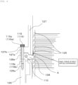
- a feature of the axial force reducing means according to Modification 1 is a configuration in which a nominal length L of the second bolt 116 is made longer, so that the gap C is formed between the head portion 116a of the second bolt 116 and the bolt fastening face 127b of the outer cylinder 127. This will be described in detail with reference to FIG. 8.
- FIG. 8 is an enlarged view of primary portions of the fastening portion of the second bolt 116 according to Modification 1.
- the nominal length L of the second bolt 116 is greater than a total value D of the length of the through hole 127a of the outer cylinder 127, the length of the through hole 128a of the water cooling spacer 128, and the screwing depth of the screw hole 126a of the outer wall 126, as illustrated in FIG. 8 . Accordingly, when tightening the second bolt 116, a tip end of the screw portion 116b of the second bolt 116 abuts a bottom portion of the screw hole 126a before the head portion 116a of the second bolt 116 comes into contact with the bolt fastening face 127b of the outer cylinder 127. As a result, the gap C is formed between the head portion 116a of the second bolt 116 and the bolt fastening face 127b.
- the axial force of the second bolt 116 does not act on the outer cylinder 127 and the water cooling spacer 128, due to the gap C being formed. That is to say, in Modification 1, the second bolt 116 itself functions as the axial force reducing means. Accordingly, the same effects and advantages as the above-described embodiment are exhibited. That is to say, deformation of the water cooling spacer 128 can be prevented. Also, the spacer 117 becomes unnecessary, thereby contributing to reduction in parts count.
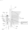
- FIG. 9 is an enlarged view of primary portions of the fastening portion of the second bolt 116 according to Modification 2.
- the stopper 118 that is made of metal is embedded being screwed into the bottom portion of the screw hole 126a.
- the stopper 118 may be made of a material other than metal, metal is more preferable since deformation of the stopper 118 due to change over time following fastening of the bolt, which can lead to loosening of bolt fastening, does not readily occur. Due to this stopper 118, the gap C is formed between the head portion 116a of the second bolt 116 and the bolt fastening face 127b of the outer cylinder 127 at the time of the tip end portion of the screw portion 116b of the second bolt 116 coming into contact with the stopper 118.
- the gap C is formed by the stopper 118, and thus the axial force of the second bolt 116 does not act on the outer cylinder 127 and the water cooling spacer 128.
- the same effects and advantages as the above-described embodiment are exhibited. That is to say, deformation of the water cooling spacer 128 can be prevented.
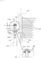
- FIG. 10 is an enlarged view of primary portions of the fastening portion of the second bolt 116 according to Modification 3.
- spring washers 159 which are elastic members, are disposed in the gap C.
- a recessed portion 127c is formed in the outer cylinder 127, and three spring washers 159 are disposed in the recessed portion 127c on top of each other. Accordingly, the recessed portion 127c is a space for accommodating the spring washers 159.
- the spring washers 159 can absorb thermal expansions, which is effective in preventing loosening of the second bolt 116.
- a configuration may be made in which a foamed material, urethane rubber, or the like, is provided in the recessed portion 127c as the elastic member, instead of the spring washers 159.
- the elastic member such as the spring washers 159 and so forth can be applied to all embodiments and modifications disclosed in the present specification.
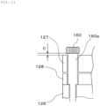
- a feature of Modification 4 is a point of using a stepped bolt 160 as the second bolt, as illustrated in FIG. 11 .
- a cylindrical portion (stepped portion) 160a of the stepped bolt 160 comes into contact with the outer wall 126, and accordingly has the same function as the spacer 117. That is to say, in Modification 4, the axial force reducing means are made up of the stepped bolt 160 in which the second bolt 116 and the spacer 117 are integrated, instead of the configuration of the second bolt 116 and the spacer 117, such that axial force does not act on the outer cylinder 127. Accordingly, the same effects and advantages as the present embodiment are exhibited by this Modification 4 as well. Also reduction in part count can be anticipated, since the spacer 117 is unnecessary. A further advantage is improved efficiency of work, since assembly is easy.
- the present invention is applicable to any vacuum pump, such as for example, a turbomolecular pump in which the water cooling spacer 128 and the outer wall 126 are integrated and make up a peripheral part, a turbomolecular pump of a configuration in which there is no water cooling spacer 128 with the outer cylinder 127 and the outer wall 126 being directly fastened, and so forth. That is to say, the present invention is applicable to portions where applying excessive axial force by bolts to a peripheral part is undesirable in a vacuum pump having a configuration in which an outer cylinder and a peripheral part are fastened by bolts.
Landscapes
- Engineering & Computer Science (AREA)
- Mechanical Engineering (AREA)
- General Engineering & Computer Science (AREA)
- Non-Positive Displacement Air Blowers (AREA)
Abstract
Description
- The present invention relates to a vacuum pump.
- Generally, in vacuum pumps represented by, for instance, turbomolecular pumps, a casing (outer cylinder) and peripheral parts (e.g., cooling spacer, base, etc.) are fastened by bolts, thus making up a housing of the vacuum pump. A rotating body that has rotor blades is accommodated within this casing, and rotates at a high speed (see PTL 1). When the rotating body fails during operation of the vacuum pump, a great tortional torque (hereinafter referred to as "destructive torque") is generated in a rotating direction of the rotating body. The destructive torque acts on the bolts fastening the casing and the peripheral parts, and accordingly the bolts need to absorb this destructive torque.
- [PTL 1]
WO 2014/045438 - In recent years, weight of the rotating body is in an increasing trend, due to increased size associated with increased workloads of pumps and change of materials to high-temperature tolerant materials associated with high-temperature demands. Greater weight of the rotating body means increased destructive torque, and the size and count of bolts increase accordingly as well. Accordingly, great axial force of the bolts is applied to the casing and the peripheral parts, and there is a possibility that the peripheral parts may be deformed. Particularly, in a case in which there is a gap between the casing and the peripheral parts in an axial direction as in PTL 1, bending moment is applied to the peripheral parts under the axial force of the bolts, and there is a concern that the peripheral parts may be deformed.
- Absorbing the increase in destructive torque without changing the axial force of the bolts can be realized by increasing a pitch circle diameter (PCD) of the bolts, for example, but this is undesirable since the vacuum pump will increase in size. Using special high-strength bolts does away with the need to increase the count of bolts, but this has problems in that versatility is poor and costs increase.
- Accordingly, it is an object of the present invention to provide a vacuum pump in which deformation of peripheral parts fastened to the outer cylinder can be prevented even if the count of bolts increases.
- In order to achieve the above object, an aspect of the present invention is a vacuum pump, including: a rotating body; an outer cylinder that accommodates the rotating body; a peripheral part that is disposed on an outer perimeter side of the rotating body and concentrically with the outer cylinder; a plurality of bolts that fasten the outer cylinder and the peripheral part; and an axial force reducing means for reducing bolt axial force acting on the outer cylinder. The axial force reducing means is provided to at least one of the plurality of bolts.
- Also, in the above configuration, the axial force reducing means preferably has a structure that forms a gap between a head portion of the bolt and a bolt fastening face that is an outer face of the outer cylinder and that faces the head portion of the bolt.
- Also, in the above configuration, preferably, a plurality of through holes, through which the plurality of bolts are passed, are provided in the outer cylinder, a plurality of screw holes, into which the plurality of bolts are screwed, are provided in the peripheral part, a cylindrically shaped spacer serving as the axial force reducing means is inserted into at least one of the plurality of through holes, and the gap is formed between the head portion of the bolt and the bolt fastening face across the spacer.
- Also, in the above configuration, preferably, a plurality of through holes, through which the plurality of bolts are passed, are provided in the outer cylinder, a plurality of screw holes, into which the plurality of bolts are screwed, are provided in the peripheral part, and the gap is formed between the head portion of the bolt and the bolt fastening face by at least one of the plurality of bolts functioning as the axial force reducing means by being formed to have a nominal length that is greater than a total value of a length of the through hole and a screwing depth of the screw hole.
- Also, in the above configuration, preferably, a plurality of through holes, through which the plurality of bolts are passed, are provided in the outer cylinder, a plurality of screw holes, into which the plurality of bolts are screwed, are provided in the peripheral part, a stopper serving as the axial force reducing means is disposed at a bottom portion of at least one of the plurality of screw holes, and the gap is formed between the head portion of the bolt and the bolt fastening face by a tip end portion of the bolt coming into contact with the stopper.
- Also, in the above configuration, the axial force reducing means preferably further includes an elastic member disposed in the gap.
- Also, in the above configuration, a count of the bolts to which the axial force reducing means is provided is preferably smaller than a count of the bolts to which the axial force reducing means is not provided.
- Also, in the above configuration, a count of the bolts to which the axial force reducing means is provided is preferably greater than a count of the bolts to which the axial force reducing means is not provided.
- Also, in the above configuration, the plurality of bolts are preferably same bolts.
- According to the vacuum pump of the present invention, deformation of peripheral parts fastened to the outer cylinder can be prevented even if the count of bolts increases. Note that problems, configurations and advantages, other than those described above, will become clear by description of an embodiment below.
-
- [
FIG. 1] FIG. 1 is a longitudinal-sectional view of a turbomolecular pump according to an embodiment of the present invention; - [
FIG. 2] FIG. 2 is a circuit diagram of an amplifier circuit of the turbomolecular pump illustrated inFIG. 1 ; - [
FIG. 3] FIG. 3 is a timing chart showing control of an amplifier control circuit in a case in which an electric current instruction value is greater than a detected value; - [
FIG. 4] FIG. 4 is a timing chart showing control of the amplifier control circuit in a case in which the electric current instruction value is smaller than a detected value; - [
FIG. 5] FIG. 5 is a diagram schematically illustrating positions of first bolts and second bolts as viewed from above the turbomolecular pump; - [
FIG. 6] FIG. 6 is an enlarged view of primary portions of a fastening portion of a first bolt; - [
FIG. 7] FIG. 7 is an enlarged view of primary portions of a fastening portion of a second bolt; - [
FIG. 8] FIG. 8 is an enlarged view of primary portions of a fastening portion of a second bolt according to Modification 1; - [
FIG. 9] FIG. 9 is an enlarged view of primary portions of a fastening portion of a second bolt according to Modification 2; - [
FIG. 10] FIG. 10 is an enlarged view of primary portions of a fastening portion of a second bolt according to Modification 3; and - [
FIG. 11] FIG. 11 is a diagram schematically illustrating a fastening portion of a second bolt according to Modification 4. - An embodiment of a vacuum pump according to the present invention will be described below with reference to the Figures, by way of example of a turbomolecular pump.
-
FIG. 1 is a longitudinal-sectional view of aturbomolecular pump 100.FIG. 1 is a configuration diagram of a turbomolecular pump used in the embodiment of the present invention. InFIG. 1 , aninlet port 101 is formed at an upper end of anouter cylinder 127, which is cylindrically shaped, in theturbomolecular pump 100. On an inner side of theouter cylinder 127, a rotatingbody 103 is provided. Provided extending radially on a peripheral portion of the rotatingbody 103 is a plurality of rotor blades 102 (102a, 102b, 102c...) serving as turbine blades for suction and exhaust of gas, the rotor blades 102 are provided in a plurality of stages. Arotor shaft 113 is attached to a center of the rotatingbody 103, and therotor shaft 113 is made to be supported by levitation in air and to be position-controlled by a five-axis control magnetic bearing, for example. The rotatingbody 103 is generally made of a metal such as aluminum, aluminum alloy, stainless, or the like. - Also, as illustrated in
FIG. 1 , awater cooling spacer 128 and anouter wall 126, which are peripheral parts, are disposed on an outer perimeter side of a rotatingbody 103. Thewater cooling spacer 128 is a ring-shaped member in which an annular cooling pipe 110 (seeFIG. 6 ) is built in. Supplying coolant water to thiscooling pipe 110 cools parts in the vicinity of thewater cooling spacer 128. That is to say, heat generated by rotation of the rotatingbody 103 is cooled by thewater cooling spacer 128. Theouter wall 126 is a cylindrically shaped member that surrounds substantially a lower half of theturbomolecular pump 100. Thewater cooling spacer 128 and theouter wall 126 are disposed below theouter cylinder 127, concentrically with theouter cylinder 127 and in that order. Theouter cylinder 127, thewater cooling spacer 128, and theouter wall 126 are integrated by being fastened by a plurality ofbolts turbomolecular pump 100 accommodating the rotatingbody 103, along with abase portion 129. - Upper-side radial-
direction electromagnets 104 are four electromagnets, disposed in pairs on an X axis and a Y axis. Four upper-side radial-direction sensors 107 are provided in close proximity to the upper-side radial-direction electromagnets 104 and corresponding to each of the upper-side radial-direction electromagnets 104. Inductance sensors, eddy current sensors, or the like, having conducting windings, are used as the upper-side radial-direction sensors 107, for example. A position of therotor shaft 113 is detected on the basis of change in inductance of the conducting windings that changes in accordance with the position of therotor shaft 113. These upper-side radial-direction sensors 107 are configured to detect radial-direction displacement of therotor shaft 113, i.e., of the rotatingbody 103 fixed thereto, to be sent to acontrol device 200. - In this
control device 200, a compensating circuit having differential (PID) adjusting functions, for example, generates excitation control command signals for the upper-side radial-direction electromagnets 104 on the basis of position signals detected by the upper-side radial-direction sensors 107, and an amplifier circuit 150 (described later) illustrated inFIG. 2 performs excitation control of the upper-side radial-direction electromagnets 104 on the basis of these excitation control command signals, thereby adjusting a radial-direction position of an upper side of therotor shaft 113. - This
rotor shaft 113 is formed of a material having high magnetic permeability (iron, stainless steel, etc.) or the like, and is arranged to be suctioned by magnetic force of the upper-side radial-direction electromagnets 104. This adjustment is performed independently for an X-axial direction and a Y-axial direction. Lower-side radial-direction electromagnets 105 and lower-side radial-direction sensors 108 are also disposed in the same way as the upper-side radial-direction electromagnets 104 and the upper-side radial-direction sensors 107, and adjust the radial-direction position of a lower side of therotor shaft 113 in the same way as with the radial-direction position of the upper side. - Further, axial-
direction electromagnets metal disc 111 that is disc-shaped and is provided at a lower portion of therotor shaft 113, above and below. Themetal disc 111 is made of a high magnetic permeability material such as iron or the like. An axial-direction sensor 109 is provided in order to detect displacement of therotor shaft 113 in the axial direction, and is configured to send axial-direction position signals thereof to thecontrol device 200. - In the
control device 200, the compensating circuit having PID controller functions, for example, generates excitation control command signals for each of the axial-direction electromagnet 106A and the axial-direction electromagnet 106B on the basis of axial-direction position signals detected by the axial-direction sensor 109, and theamplifier circuit 150 performs excitation control of each of the axial-direction electromagnet 106A and the axial-direction electromagnet 106B on the basis of these excitation control command signals, whereby the axial-direction electromagnet 106A suctions themetal disc 111 upward by magnetic force and the axial-direction electromagnet 106B suctions themetal disc 111 downward, thereby adjusting the axial-direction position of therotor shaft 113. - Thus, the
control device 200 adjusts the magnetic force that the axial-direction electromagnets metal disc 111 as appropriate, causing magnetic levitation of therotor shaft 113 in the axial direction, so as to be held in air without contact. Note that theamplifier circuit 150 that performs excitation control of the upper-side radial-direction electromagnets 104, the lower-side radial-direction electromagnets 105, and the axial-direction electromagnets - Also, a
motor 121 is provided with a plurality of magnetic poles disposed perimetrically surrounding therotor shaft 113. Each magnetic pole is controlled by thecontrol device 200 so as to rotationally drive therotor shaft 113 through electromagnetic force acting between itself and therotor shaft 113. An unshown rotational velocity sensor, such a Hall device, a resolver, an encoder, or the like, for example, is assembled into themotor 121, and rotational velocity of therotor shaft 113 is detected by detection signals from this rotational velocity sensor. - Further, an unshown phase sensor is attached in a proximity of the lower-side radial-
direction sensors 108 for example, and is arranged to detect a phase of rotation of therotor shaft 113. Thecontrol device 200 uses both of detection signals of this phase sensor and the rotational velocity sensor to detect the position of the magnetic poles. - A plurality of stator blades 123 (123a, 123b, 123c...) is disposed with a slight spacing as to the rotor blades 102 (102a, 102b, 102c...). The rotor blades 102 (102a, 102b, 102c...) are each formed inclined at a predetermined angle from a plane perpendicular to an axial line of the
rotor shaft 113, in order to transport molecules of exhaust gas downward through collision therewith. The stator blades 123 (123a, 123b, 123c...) are made of a metal such as, for example, aluminum, iron, stainless steel, copper, or the like, or a metal such as an alloy containing any of these metals as a component. - The stator blades 123 are also formed inclined at a predetermined angle from the plane perpendicular to the axial line of the
rotor shaft 113 in the same way, and are disposed extending toward the inner side of theouter cylinder 127, alternating with the stages of rotor blades 102. Outer circumferential ends of the stator blades 123 are supported in a state of being inserted between a plurality of stator blade spacers 125 (125a, 125b, 125c...) that are stacked up. - The
stator blade spacers 125 are ring-shaped members, and are made of a metal such as, for example, aluminum, iron, stainless steel, copper, or the like, or a metal such as an alloy containing any of these metals as a component. Theouter cylinder 127 is fixed on outer perimeters of thestator blade spacers 125, with a slight gap therebetween. Abase portion 129 is disposed at a bottom portion of the outer cylinder 127 (more specifically, a bottom portion of the outer wall 126). Anoutlet port 133 is formed above thebase portion 129 so as to externally communicate. Exhaust gas that enters theinlet port 101 from a chamber (a vacuum chamber) side and is transported toward thebase portion 129 is sent to theoutlet port 133. - Further, depending on the use of the
turbomolecular pump 100, a threadedspacer 131 is disposed between a bottom portion of thestator blade spacers 125 and thebase portion 129. The threadedspacer 131 is a cylindrically shaped member made of aluminum, copper, stainless steel, or iron, or a metal such as an alloy containing any of these metals as a component, or the like, with a plurality ofthread grooves 131a that is spiral-like and that is ditched in an inner circumferential face thereof. A direction of spiraling of thethread grooves 131a is a direction in which molecules of exhaust gas are transported toward theoutlet port 133, when the molecules move in a rotational direction of therotating body 103. Acylindrical portion 102d that extends downward continuing from the rotor blades 102 (102a, 102b, 102c...) is provided at a bottommost portion of therotating body 103. An outer circumferential face of thiscylindrical portion 102d is cylindrically shaped and is enlarged toward the inner circumferential face of the threadedspacer 131, and is in close proximity with the inner circumferential face of the threadedspacer 131 across a predetermined gap. Exhaust gas transported to thethread grooves 131a by the rotor blades 102 and the stator blades 123 is sent to thebase portion 129, being guided by thethread grooves 131a. - More specifically, the exhaust gas guided to the
thread grooves 131a is fed to anannular space 135 formed above thebase portion 129, circles theannular space 135, and is externally discharged via theoutlet port 133. Thisannular space 135 is a space that is annular in form, and is defined by thecylindrical portion 102d of the rotating body 103 (rotor), the threaded spacer (stator portion) 131, aheater spacer 153, and thebase portion 129. - Now, the
heater spacer 153 is a cylindrically shaped member, and is integrally configured with the threadedspacer 131 in the present embodiment. As a matter of course, theheater spacer 153 and the threadedspacer 131 may be configured separately. Theheater spacer 153 is made of a metal such as, for example, aluminum, stainless steel, or the like. Aheater 195 serving as heating means is inserted into theheater spacer 153, and the threadedspacer 131 is heated via theheater spacer 153 by theheater 195 generating heat. Exhaust gas flowing through theannular space 135 is also heated by theheater 195. This suppresses deposited matter from being produced due to the temperature of the exhaust gas becoming lower. - The
base portion 129 is a disc-shaped member making up a base portion of theturbomolecular pump 100, and generally is made of a metal such as iron, aluminum, stainless steel, or the like. Thebase portion 129 serves to physically hold theturbomolecular pump 100, and also has functions of a thermal conduction path. Accordingly, a metal that has rigidity, and also has high thermal conductivity, such as iron, aluminum, copper, or the like, is preferably used for thebase portion 129. - In this configuration, upon the rotor blades 102 being rotationally driven by the
motor 121 along with therotor shaft 113, exhaust gas is sucked through theinlet port 101 from the unshown chamber, by operations of the rotor blades 102 and the stator blades 123. The rotational velocity of the rotor blades 102 normally is 20,000 rpm to 90,000 rpm, and peripheral velocity at tip ends of the rotor blades 102 reaches 200 m/s to 400 m/s. Exhaust gas sucked through theinlet port 101 passes between the rotor blades 102 and the stator blades 123, and is transported to thebase portion 129. At this time, the temperature of the rotor blades 102 rises due to frictional heat generated at the time of the exhaust gas coming into contact with the rotor blades 102, conduction of heat generated at themotor 121, and this heat is conveyed to the side of the stator blades 123 by radiance, conduction by gas molecules of the exhaust gas, and so forth. - The
stator blade spacers 125 are joined with each other on an outer perimeter portion, and externally convey heat that the stator blades 123 receive from the rotor blades 102, friction heat generated at the time of the exhaust gas coming into contact with the stator blades 123, and so forth. - Note that description has been made above that the threaded
spacer 131 is disposed on an outer perimeter of thecylindrical portion 102d of therotating body 103, with thethread grooves 131a ditched in the inner circumferential face of the threadedspacer 131. However, there are reverse cases in which thread grooves are ditched in the outer circumferential face of thecylindrical portion 102d, and a spacer having a cylindrically shaped inner circumferential face is disposed therearound. - Also, depending on the use of the
turbomolecular pump 100, there are cases in which a perimeter of an electrical component portion configured of the upper-side radial-direction electromagnets 104, the upper-side radial-direction sensors 107, themotor 121, the lower-side radial-direction electromagnets 105, the lower-side radial-direction sensors 108, the axial-direction electromagnets direction sensor 109, and so forth, is covered by astator column 122, so that gas suctioned through theinlet port 101 does not intrude into the electrical component portion, and inside of thisstator column 122 is maintained at a predetermined pressure by a purge gas. - In this case, unshown piping is disposed in the
base portion 129, and the purge gas is introduced through this piping. The introduced purge gas is sent out to theoutlet port 133 through gaps between aprotective bearing 120 and therotor shaft 113, between a rotor and a stator of themotor 121, and between thestator column 122 and inner-circumferential-side cylindrical portions of the rotor blades 102. Note that thestator column 122 is erected at a center portion of thebase portion 129, as illustrated inFIG. 1 . Also, acoolant pipe 149 is provided to thebase portion 129 in the present embodiment, as cooling means. Supplying coolant water to thecoolant pipe 149 maintains thebase portion 129 and thestator column 122 at a suitable temperature. - Now, the
turbomolecular pump 100 requires control based on identification of model, and individually-adjusted unique parameters (e.g., various characteristics corresponding to the model). Theturbomolecular pump 100 is provided with anelectronic circuit portion 141 within a main unit thereof, in order to store these control parameters. Theelectronic circuit portion 141 is configured of electronic parts such as semiconductor memory like electrically erasable programmable read-only memory (EEPROM), semiconductor devices for access thereto and so forth, asubstrate 143 on which these are mounted, and so forth. Theelectronic circuit portion 141 is accommodated below an unshown rotational velocity sensor near a middle, for example, of thebase portion 129 that makes up a lower portion of theturbomolecular pump 100, and is closed off by abottom cover 145 that is airtight. - Now, there are some process gasses introduced into the chamber during manufacturing processes of semiconductors that have a nature of solidifying when a pressure thereof becomes higher than a predetermined value or a temperature thereof becoming lower than a predetermined value. Inside of the
turbomolecular pump 100, the pressure of exhaust gas is lowest at theinlet port 101 and highest at theoutlet port 133. When the pressure of the process gas becomes higher than the predetermined value, or the temperature thereof becoming lower than the predetermined value, while being transported from theinlet port 101 to theoutlet port 133, the process gas solidifies, and adheres to the inside of theturbomolecular pump 100 and thus is deposited. - For example, in a case of using tetrachlorosilane (SiCl4) as a process gas in an aluminum etching device, it can be understood from a vapor gas curve that precipitation of a solid product (e.g., aluminum chloride (AlCl3)) will occur under low vacuum (760 torr to 10-2 torr) and low temperature (approximately 20°C), and become adhered to and deposited on the inside of the
turbomolecular pump 100. Accordingly, when deposition of a precipitate of a process gas on the inside of theturbomolecular pump 100 occurs, the deposited matter narrows pump channels, causing deterioration in performance of theturbomolecular pump 100. The aforementioned product tends to solidify and adhere at portions where pressure is high, such as around theoutlet port 133 and around the threadedspacer 131. - Accordingly, in order to solve this problem, an arrangement is conventionally made in which an unshown heater, and a
coolant pipe 149 that is annular in shape, are wound onto an outer perimeter of thebase portion 129 or the like, and also an unshown temperature sensor (e.g., a thermistor) is embedded in thebase portion 129, for example. Control of heating by the heater and cooling by thecoolant pipe 149 so as to maintain the temperature of thebase portion 129 at a constant high temperature (set temperature) on the basis of signals from this temperature sensor is performed (hereinafter referred to as "temperature management system" (TMS)). - Next, the
amplifier circuit 150 that performs excitation control of the upper-side radial-direction electromagnets 104, the lower-side radial-direction electromagnets 105, and the axial-direction electromagnets turbomolecular pump 100 configured thus. A circuit diagram of thisamplifier circuit 150 is shown inFIG. 2 . - In
FIG. 2 , one end of an electromagnet winding 151 that makes up the upper-side radial-direction electromagnets 104 or the like is connected to a positive terminal 171a of anelectric power source 171 via atransistor 161, and another end thereof is connected to anegative terminal 171b of theelectric power source 171 via an electric current detectingcircuit 181 and atransistor 162. Thetransistors - At this time, the
transistor 161 is arranged such that acathode terminal 161a of the diode thereof is connected to thepositive terminal 171a, and ananode terminal 161b is connected to one end of the electromagnet winding 151. Also, thetransistor 162 is arranged such that acathode terminal 162a of the diode thereof is connected to the electric current detectingcircuit 181, and ananode terminal 162b is connected to thenegative terminal 171b. - At the same time, a
cathode terminal 165a of a current-regenerative diode 165 is connected to one end of the electromagnet winding 151, and ananode terminal 165b thereof is connected to thenegative terminal 171b. In the same way, acathode terminal 166a of a current-regenerative diode 166 is connected to thepositive terminal 171a, and ananode terminal 166b thereof is connected to the other end of the electromagnet winding 151 via the electric current detectingcircuit 181. The electric current detectingcircuit 181 is made up of, for example, a Hall sensor type current sensor, an electrical resistance component, or the like. - The
amplifier circuit 150 configured as described above corresponds to a single electromagnet. Accordingly, in a case in which the magnetic bearing is a five-axis control magnetic bearing, and there is a total of tenelectromagnets amplifier circuits 150 are configured in the same way for each of the electromagnets, and there will be tenamplifier circuits 150 that are connected in parallel with respect to theelectric power source 171. - Further, an
amplifier control circuit 191 is made up of an unshown digital signal processor unit (hereinafter referred to as "DSP unit") of thecontrol device 200, for example, and thisamplifier control circuit 191 is arranged to switch on/off of thetransistors - The
amplifier control circuit 191 is arranged to compare an electric current value detected by the electric current detecting circuit 181 (a signal in which this electric current value is reflected will be referred to as "electriccurrent detection signal 191c") with a predetermined electric current instruction value. Theamplifier control circuit 191 is arranged to decide a magnitude of a pulse width (pulse width time Tpl, Tp2) to be generated in a control cycle Ts, which is one cycle under pulse-width modulation (PWM) control, on the basis of a result of this comparison. Consequently, gate drive signals 191a and 191b that have these pulse widths are output from theamplifier control circuit 191 to gate terminals of thetransistors - Note that at the time of passing a resonance point during acceleration operation of rotational velocity of the
rotating body 103, at the time of disturbance occurring during constant speed operation, or the like, there is a need to perform positional control of therotating body 103 at high speed and with a strong force. Accordingly, a high voltage around 50 V, for example, is used for theelectric power source 171, so that sudden increase (or decrease) of electric current flowing through the electromagnet winding 151 can be performed. Also, a capacitor (omitted from illustration) is usually connected between thepositive terminal 171a and thenegative terminal 171b of theelectric power source 171, for stability of theelectric power source 171. - In this configuration, when both of the
transistors - Also, when one of the
transistors amplifier circuit 150 in this way enables hysteresis loss at theamplifier circuit 150 to be reduced, and electric power consumption can be kept low for the overall circuit. Also, controlling thetransistors turbomolecular pump 100 to be reduced. Further, measuring the flywheel current at the electric current detectingcircuit 181 enables detection of the electromagnet current iL flowing at the electromagnet winding 151. - That is to say, in a case in which a detected current value is smaller than the electric current instruction value, both of the
transistors FIG. 3 . Accordingly, the electromagnet current iL during this period increases toward an electric current value iLmax (omitted from illustration) that can be made to flow from the positive terminal 171a to thenegative terminal 171b via thetransistors - Conversely, in a case in which a detected current value is greater than the electric current instruction value, both of the
transistors FIG. 4 . Accordingly, the electromagnet current iL during this period decreases toward an electric current value iLmin (omitted from illustration) that can be regenerated from thenegative terminal 171b to thepositive terminal 171a via thediodes 165 and 166. - In either case, one of the
transistors amplifier circuit 150. - Next, a feature portion of the
turbomolecular pump 100 according to the present embodiment will be described in detail. In the present embodiment, theouter cylinder 127, thewater cooling spacer 128, and theouter wall 126 are fixed by the plurality ofbolts first bolts 115 andsecond bolts 116. Note that thefirst bolts 115 and thesecond bolts 116 are the same. -
FIG. 5 is a diagram schematically illustrating positions of thefirst bolts 115 and thesecond bolts 116 as viewed from above theturbomolecular pump 100. Thefirst bolts 115 and thesecond bolts 116 are disposed equidistantly on a concentric circle as a center O of theouter cylinder 127, as illustrated inFIG. 5 , but do not have to be disposed equidistantly, and thefirst bolts 115 and thesecond bolts 116 do not necessarily have to be disposed on a concentric circle. Also, the count of thefirst bolts 115 is 12 and the count of thesecond bolts 116 is four in the present embodiment, with the count of thesecond bolts 116 being smaller than the count of thefirst bolts 115. As a matter of course, the count of thesecond bolts 116 may be greater than the count of thefirst bolts 115, and the count of both may be the same. A suitable count of bolts can be selected taking into consideration an axial force necessary to fasten theouter cylinder 127, thewater cooling spacer 128, and theouter wall 126 by bolting, and destructive torque that theturbomolecular pump 100 is subjected to at the time of therotating body 103 failing. InFIG. 5 , thefirst bolts 115 are tightened by a normal technique, and thesecond bolts 116 are tightened via later-described axial force reducing means (spacers 117). -
FIG. 6 is an enlarged view of primary portions of a fastening portion of thefirst bolt 115, andFIG. 7 is an enlarged view of primary portions of a fastening portion of thesecond bolt 116. As illustrated inFIGS. 6 and7 , throughholes 127a through which thefirst bolts 115 and thesecond bolts 116 pass are provided in theouter cylinder 127. In the same way, throughholes 128a are provided in thewater cooling spacer 128. Also, screwholes 126a, to whichscrew portions 115b of thefirst bolts 115 and screwportions 116b of thesecond bolts 116 are screwed, are provided in theouter wall 126. By inserting thebolts screw holes 126a through the throughholes outer cylinder 127, thewater cooling spacer 128, and theouter wall 126 are integrally fixed. Note that the throughholes second bolts 116 pass are formed with a greater diameter than a diameter of the throughholes first bolts 115 pass, due to the later-describedspacers 117 being inserted therein. - As illustrated in
FIG. 6 , thefirst bolt 115 is inserted into thescrew hole 126a via the throughholes head portion 115a of thefirst bolt 115 comes into contact with abolt fastening face 127b, and the axial force of thefirst bolt 115 acts on theouter cylinder 127 and thewater cooling spacer 128. - Conversely, the
second bolt 116 is arranged to be tightened via thespacer 117, as illustrated inFIG. 7 . A configuration of thespacer 117 serving as the axial force reducing means will be described in detail below. - The
spacer 117 is a member that is tubularly formed and made of metal, and is inserted in the throughhole 127a of theouter cylinder 127 and the throughhole 128a of thewater cooling spacer 128, as illustrated inFIG. 7 . Note that while thespacer 117 may be made of a material other than metal, metal is more preferable since deformation of thespacer 117 due to change over time following fastening of the bolt, which can lead to loosening of bolt fastening, does not readily occur. Thespacer 117 has an outer diameter such that thespacer 117 is smoothly removably insertable into the throughholes screw portion 116b of thesecond bolt 116 is precisely removably insertable therein. Thespacer 117 is formed having a dimension that is slightly longer than a total of a length of the throughhole 127a and a length of the throughhole 128a. Accordingly, when inserted into the throughholes spacer 117 is in a state of slightly protruding from a surface (bolt fastening face 127b) of theouter cylinder 127, as illustrated inFIG. 7 . - When the
second bolt 116 is inserted into thescrew hole 126a via thespacer 117 and tightened at the predetermined torque, the length of thespacer 117 impedes so that ahead portion 116a of thesecond bolt 116 cannot come into contact with thebolt fastening face 127b. Accordingly, a gap C is formed between thehead portion 116a of thesecond bolt 116, and thebolt fastening face 127b that is the portion of the surface of theouter cylinder 127 that faces thehead portion 116a. Accordingly, the axial force of thesecond bolt 116 acts only on theouter wall 126, and does not act on theouter cylinder 127 and thewater cooling spacer 128. That is to say, thespacer 117 reduces (prevents) the axial force of thesecond bolt 116 from acting on theouter cylinder 127 and thewater cooling spacer 128. - Advantages of the present embodiment configured in this way will be described next.
- When the weight of the
rotating body 103 increases due to specification changes or the like, for example, the destructive torque increases, as a matter of course. The increase in destructive torque can be absorbed by using special bolts, increasing the PCD of the bolts, or the like. However, if employing such measures is undesirable, the count of thebolts - In doing so, tightening not only the
first bolts 115 but thesecond bolts 116 as well using the conventional technique illustrated inFIG. 6 may cause deformation of thewater cooling spacer 128, due to excessive axial force being applied to theouter cylinder 127 and thewater cooling spacer 128. - To describe in further detail, when the
second bolts 116 are tightened by the conventional technique illustrated inFIG. 6 , axial force of thesecond bolts 116 acts on theouter cylinder 127 and thewater cooling spacer 128. Accordingly, an outer perimeter side portion of thewater cooling spacer 128 is tightened and fixed by thesecond bolts 116. That is to say, the outer perimeter side portion of thewater cooling spacer 128 becomes a fixed end. - The axial force of the
second bolt 116 also acts on theouter cylinder 127, and accordingly theouter cylinder 127 is subjected to downward axial force illustrated inFIG. 6 . Accordingly, aflange portion 127f (seeFIG. 1 ) at an upper end of theouter cylinder 127 is also subjected to downward axial force. Theflange portion 127f of theouter cylinder 127 and thestator blade spacer 125a at an uppermost tier are in contact, and the stator blade spacers 125 (125a, 125b, 125c ...) of each tier are also each in contact. Accordingly, when the axial force of thesecond bolts 116 is applied to theouter cylinder 127, the axial force is conveyed to thestator blade spacers 125. That is to say, theflange portion 127f of theouter cylinder 127 presses thestator blade spacers 125 downward under the axial force of thesecond bolts 116. Thestator blade spacers 125 and thewater cooling spacer 128 are in contact in the axial direction, and accordingly axial force applied to theouter cylinder 127 acts on an inner circumferential side portion of the water cooling spacer 128 (portion indicated by hatching A inFIG. 6 ) via thestator blade spacers 125, as illustrated inFIG. 6 . - That is to say, the outer perimeter side portion of the
water cooling spacer 128 becomes a fixed end, the inner circumferential side becomes a free end, and the axial force of thesecond bolts 116 acts downward on this free end side. Accordingly, bending moment acts on thewater cooling spacer 128 with the fixed end serving as a fulcrum, and the portion on the inner circumferential side is deformed (bent) downwards. Thus, there is a concern that simply increasing the count of bolts to absorb the increase in destructive torque will lead to deformation of thewater cooling spacer 128, and accordingly is not necessarily preferable. - Conversely, according to the present embodiment, the
second bolts 116 fasten theouter cylinder 127, thewater cooling spacer 128, and theouter wall 126 via thespacers 117, as illustrated inFIG. 7 , and accordingly the axial force of thesecond bolts 116 does not act on thewater cooling spacer 128. That is to say, downward force is not applied to the hatched portion inFIG. 7 . Thus, according to the present embodiment, even when the weight of therotating body 103 increases due to specification changes or the like of theturbomolecular pump 100, and the destructive torque increases, the increase in destructive torque can be absorbed by increasing the count of bolts, while preventing deformation of thewater cooling spacer 128. - That is to say, the present embodiment is capable of securing fastening of the
outer cylinder 127, thewater cooling spacer 128, and theouter wall 126 in the axial direction by the axial force of thefirst bolts 115, and can absorb the destructive torque by thefirst bolts 115 and thesecond bolts 116 while preventing deformation of thewater cooling spacer 128. - Thus, according to the present embodiment, even in a case in which there is demand for specification changes due to increased size of the
turbomolecular pump 100 and higher temperatures, this can be handled simply by design change in which the count ofbolts - Next, Modification 1 of the axial force reducing means will be described. A feature of the axial force reducing means according to Modification 1 is a configuration in which a nominal length L of the
second bolt 116 is made longer, so that the gap C is formed between thehead portion 116a of thesecond bolt 116 and thebolt fastening face 127b of theouter cylinder 127. This will be described in detail with reference toFIG. 8. FIG. 8 is an enlarged view of primary portions of the fastening portion of thesecond bolt 116 according to Modification 1. - In Modification 1, the nominal length L of the
second bolt 116 is greater than a total value D of the length of the throughhole 127a of theouter cylinder 127, the length of the throughhole 128a of thewater cooling spacer 128, and the screwing depth of thescrew hole 126a of theouter wall 126, as illustrated inFIG. 8 . Accordingly, when tightening thesecond bolt 116, a tip end of thescrew portion 116b of thesecond bolt 116 abuts a bottom portion of thescrew hole 126a before thehead portion 116a of thesecond bolt 116 comes into contact with thebolt fastening face 127b of theouter cylinder 127. As a result, the gap C is formed between thehead portion 116a of thesecond bolt 116 and thebolt fastening face 127b. - Also, a similar structure can be made by making the screwing depth of the
screw hole 126a for thesecond bolt 116 to be shorter than the screwing depth of thescrew hole 126a for thefirst bolt 115. - According to the configuration of this Modification 1, the axial force of the
second bolt 116 does not act on theouter cylinder 127 and thewater cooling spacer 128, due to the gap C being formed. That is to say, in Modification 1, thesecond bolt 116 itself functions as the axial force reducing means. Accordingly, the same effects and advantages as the above-described embodiment are exhibited. That is to say, deformation of thewater cooling spacer 128 can be prevented. Also, thespacer 117 becomes unnecessary, thereby contributing to reduction in parts count. - Next, Modification 2 of the axial force reducing means will be described. A feature of Modification 2 is a point of using a
stopper 118 as the axial force reducing means instead of thespacer 117. This will be described in detail with reference toFIG. 9. FIG. 9 is an enlarged view of primary portions of the fastening portion of thesecond bolt 116 according to Modification 2. - As illustrated in
FIG. 9 , thestopper 118 that is made of metal is embedded being screwed into the bottom portion of thescrew hole 126a. Note that while thestopper 118 may be made of a material other than metal, metal is more preferable since deformation of thestopper 118 due to change over time following fastening of the bolt, which can lead to loosening of bolt fastening, does not readily occur. Due to thisstopper 118, the gap C is formed between thehead portion 116a of thesecond bolt 116 and thebolt fastening face 127b of theouter cylinder 127 at the time of the tip end portion of thescrew portion 116b of thesecond bolt 116 coming into contact with thestopper 118. - According to this Modification 2, the gap C is formed by the
stopper 118, and thus the axial force of thesecond bolt 116 does not act on theouter cylinder 127 and thewater cooling spacer 128. Thus, the same effects and advantages as the above-described embodiment are exhibited. That is to say, deformation of thewater cooling spacer 128 can be prevented. - Next, Modification 3 of the axial force reducing means will be described. A feature of Modification 3 is a point of disposing a plurality of
spring washers 159 in the gap C, in addition to using thestopper 118 as the axial force reducing means. This will be described in detail with reference toFIG. 10. FIG. 10 is an enlarged view of primary portions of the fastening portion of thesecond bolt 116 according to Modification 3. - As illustrated in
FIG. 10 , in Modification 3,spring washers 159, which are elastic members, are disposed in the gap C. Specifically, a recessedportion 127c is formed in theouter cylinder 127, and threespring washers 159 are disposed in the recessedportion 127c on top of each other. Accordingly, the recessedportion 127c is a space for accommodating thespring washers 159. - According to this Modification 3, the
spring washers 159 can absorb thermal expansions, which is effective in preventing loosening of thesecond bolt 116. Note that a configuration may be made in which a foamed material, urethane rubber, or the like, is provided in the recessedportion 127c as the elastic member, instead of thespring washers 159. As a matter of course, the elastic member such as thespring washers 159 and so forth can be applied to all embodiments and modifications disclosed in the present specification. - Next, Modification 4 of the axial force reducing means will be described. A feature of Modification 4 is a point of using a stepped
bolt 160 as the second bolt, as illustrated inFIG. 11 . A cylindrical portion (stepped portion) 160a of the steppedbolt 160 comes into contact with theouter wall 126, and accordingly has the same function as thespacer 117. That is to say, in Modification 4, the axial force reducing means are made up of the steppedbolt 160 in which thesecond bolt 116 and thespacer 117 are integrated, instead of the configuration of thesecond bolt 116 and thespacer 117, such that axial force does not act on theouter cylinder 127. Accordingly, the same effects and advantages as the present embodiment are exhibited by this Modification 4 as well. Also reduction in part count can be anticipated, since thespacer 117 is unnecessary. A further advantage is improved efficiency of work, since assembly is easy. - It should be noted that the present invention is not limited to the above-described embodiment, various modifications can be made without departing from the spirit and scope of the present invention, and all technical matters encompassed by the technological concept described in the Claims are an object of the present invention. Although the embodiment shows a preferred example, one skilled in the art will be able to realize various substitutions, alterations, modifications, combinations, and improvements, from the content disclosed in the present specifications, and these are encompassed by the technical scope described in the attached Claims.
- The present invention is applicable to any vacuum pump, such as for example, a turbomolecular pump in which the
water cooling spacer 128 and theouter wall 126 are integrated and make up a peripheral part, a turbomolecular pump of a configuration in which there is nowater cooling spacer 128 with theouter cylinder 127 and theouter wall 126 being directly fastened, and so forth. That is to say, the present invention is applicable to portions where applying excessive axial force by bolts to a peripheral part is undesirable in a vacuum pump having a configuration in which an outer cylinder and a peripheral part are fastened by bolts. -
- 100 Turbomolecular pump (vacuum pump)
- 101 Inlet port
- 102 (102a, 102b, 102c) Rotor blade
- 102d Cylindrical portion
- 103 Rotating body
- 115 First bolt
- 116 Second bolt
- 116a Head portion
- 116b Screw portion
- 117 Spacer (axial force reducing means)
- 118 Stopper (axial force reducing means)
- 122 Stator column
- 123 (123a, 123b, 123c) Stator blade
- 125 (125a, 125b, 125c) Stator blade spacer
- 126 Outer wall (peripheral part)
- 126a Screw hole
- 127 Outer cylinder
- 127a Through hole
- 127b Bolt fastening face
- 127c Recessed portion
- 128 Water cooling spacer (peripheral part)
- 128a Through hole
- 129 Base portion
- 131 Threaded spacer
- 133 Outlet port
- 159 Spring washer
- 160 Stepped bolt (second bolt)
- C Gap
Claims (9)
- A vacuum pump, comprising:a rotating body;an outer cylinder that accommodates the rotating body;a peripheral part that is disposed on an outer perimeter side of the rotating body and concentrically with the outer cylinder; anda plurality of bolts that fasten the outer cylinder and the peripheral part; andan axial force reducing means for reducing bolt axial force acting on the outer cylinder, whereinthe axial force reducing means is provided to at least one of the plurality of bolts.
- The vacuum pump according to claim 1,
wherein the axial force reducing means has a structure that forms a gap between a head portion of the bolt and a bolt fastening face that is an outer face of the outer cylinder and that faces the head portion of the bolt. - The vacuum pump according to claim 2, whereina plurality of through holes, through which the plurality of bolts are passed, are provided in the outer cylinder,a plurality of screw holes into which the plurality of bolts are screwed are provided in the peripheral part,a cylindrically shaped spacer serving as the axial force reducing means is inserted into at least one of the plurality of through holes, andthe gap is formed between the head portion of the bolt and the bolt fastening face across the spacer.
- The vacuum pump according to claim 2, whereina plurality of through holes, through which the plurality of bolts are passed, are provided in the outer cylinder,a plurality of screw holes, into which the plurality of bolts are screwed, are provided in the peripheral part, andthe gap is formed between the head portion of the bolt and the bolt fastening face by at least one of the plurality of bolts functioning as the axial force reducing means by being formed to have a nominal length that is greater than a total value of a length of the through hole and a screwing depth of the screw hole.
- The vacuum pump according to claim 2, whereina plurality of through holes, through which the plurality of bolts are passed, are provided in the outer cylinder,a plurality of screw holes, into which the plurality of bolts are screwed, are provided in the peripheral part,a stopper serving as the axial force reducing means is disposed at a bottom portion of at least one of the plurality of screw holes, andthe gap is formed between the head portion of the bolt and the bolt fastening face by a tip end portion of the bolt coming into contact with the stopper.
- The vacuum pump according to any one of claims 2 to 5, wherein
the axial force reducing means further includes an elastic member disposed in the gap. - The vacuum pump according to any one of claims 1 to 6, wherein
a count of the bolts to which the axial force reducing means is provided is smaller than a count of the bolts to which the axial force reducing means is not provided. - The vacuum pump according to any one of claims 1 to 7, wherein
a count of the bolts to which the axial force reducing means is provided is greater than a count of the bolts to which the axial force reducing means is not provided. - The vacuum pump according to any one of claims 1 to 8, wherein
the plurality of bolts are same bolts.
Applications Claiming Priority (2)
| Application Number | Priority Date | Filing Date | Title |
|---|---|---|---|
| JP2022038281A JP7625548B2 (en) | 2022-03-11 | 2022-03-11 | Vacuum pump |
| PCT/JP2023/008069 WO2023171566A1 (en) | 2022-03-11 | 2023-03-03 | Vacuum pump |
Publications (2)
| Publication Number | Publication Date |
|---|---|
| EP4491881A1 true EP4491881A1 (en) | 2025-01-15 |
| EP4491881A4 EP4491881A4 (en) | 2026-03-04 |
Family
ID=82324094
Family Applications (1)
| Application Number | Title | Priority Date | Filing Date |
|---|---|---|---|
| EP23766742.3A Pending EP4491881A4 (en) | 2022-03-11 | 2023-03-03 | VACUUM PUMP |
Country Status (9)
| Country | Link |
|---|---|
| US (1) | US12510085B2 (en) |
| EP (1) | EP4491881A4 (en) |
| JP (1) | JP7625548B2 (en) |
| KR (1) | KR20240157020A (en) |
| CN (1) | CN119096059A (en) |
| GB (1) | GB202208031D0 (en) |
| IL (1) | IL314726A (en) |
| TW (1) | TW202342879A (en) |
| WO (1) | WO2023171566A1 (en) |
Family Cites Families (17)
| Publication number | Priority date | Publication date | Assignee | Title |
|---|---|---|---|---|
| JPH06260329A (en) | 1993-03-05 | 1994-09-16 | Toshiba Corp | Fixing structure for ground coil |
| JP3448370B2 (en) | 1994-10-25 | 2003-09-22 | 積水化学工業株式会社 | Edge detection method of workpiece to be applied to welding robot |
| JP2001241393A (en) * | 1999-12-21 | 2001-09-07 | Seiko Seiki Co Ltd | Vacuum pump |
| JP4126212B2 (en) * | 2001-11-19 | 2008-07-30 | エドワーズ株式会社 | Vacuum pump |
| JP2006063969A (en) * | 2004-07-30 | 2006-03-09 | Shimadzu Corp | Rotary vacuum pump, vacuum device and pump connection structure |
| FR2893094B1 (en) * | 2005-11-10 | 2011-11-11 | Cit Alcatel | FIXING DEVICE FOR A VACUUM PUMP |
| DE202008010092U1 (en) * | 2008-07-28 | 2009-12-10 | Sfs Intec Holding Ag | Device for connecting a threaded rod to steel parts |
| US8414258B2 (en) * | 2009-11-13 | 2013-04-09 | General Electric Company | Support bar for turbine diaphragm that facilitates reduced maintenance cycle time and cost |
| JP5832090B2 (en) * | 2010-12-15 | 2015-12-16 | 三菱重工業株式会社 | Turbocharger housing seal structure |
| CN104350283B (en) | 2012-09-24 | 2016-08-24 | 株式会社岛津制作所 | turbomolecular pump |
| JP6000077B2 (en) | 2012-11-09 | 2016-09-28 | 三菱重工業株式会社 | Exhaust turbine support structure |
| DE102013109637A1 (en) * | 2013-09-04 | 2015-03-05 | Pfeiffer Vacuum Gmbh | Vacuum pump and arrangement with a vacuum pump |
| DE102014103510B4 (en) * | 2014-03-14 | 2016-02-25 | Pfeiffer Vacuum Gmbh | Vacuum pump damper |
| US10316695B2 (en) * | 2015-12-10 | 2019-06-11 | General Electric Company | Metallic attachment system integrated into a composite structure |
| JP6934781B2 (en) * | 2017-09-06 | 2021-09-15 | 株式会社日立インダストリアルプロダクツ | Multi-stage centrifugal fluid machine |
| JP7514609B2 (en) | 2019-10-28 | 2024-07-11 | エドワーズ株式会社 | Vacuum pump |
| US11933346B1 (en) * | 2023-05-12 | 2024-03-19 | Nokia Solutions And Networks Oy | Removable shoulder screw |
-
2022
- 2022-03-11 JP JP2022038281A patent/JP7625548B2/en active Active
- 2022-05-31 GB GBGB2208031.1A patent/GB202208031D0/en not_active Ceased
-
2023
- 2023-03-02 TW TW112107488A patent/TW202342879A/en unknown
- 2023-03-03 IL IL314726A patent/IL314726A/en unknown
- 2023-03-03 WO PCT/JP2023/008069 patent/WO2023171566A1/en not_active Ceased
- 2023-03-03 KR KR1020247026995A patent/KR20240157020A/en active Pending
- 2023-03-03 CN CN202380022369.XA patent/CN119096059A/en active Pending
- 2023-03-03 US US18/836,721 patent/US12510085B2/en active Active
- 2023-03-03 EP EP23766742.3A patent/EP4491881A4/en active Pending
Also Published As
| Publication number | Publication date |
|---|---|
| JP7625548B2 (en) | 2025-02-03 |
| IL314726A (en) | 2024-10-01 |
| EP4491881A4 (en) | 2026-03-04 |
| JP2023132764A (en) | 2023-09-22 |
| GB202208031D0 (en) | 2022-07-13 |
| WO2023171566A1 (en) | 2023-09-14 |
| US20250163920A1 (en) | 2025-05-22 |
| CN119096059A (en) | 2024-12-06 |
| TW202342879A (en) | 2023-11-01 |
| US12510085B2 (en) | 2025-12-30 |
| KR20240157020A (en) | 2024-10-31 |
Similar Documents
| Publication | Publication Date | Title |
|---|---|---|
| US9093938B2 (en) | Motor driver circuit and vacuum pump having the motor driver circuit | |
| EP4325060A1 (en) | Turbo-molecular pump | |
| EP4283131A1 (en) | Vacuum pump, rotational solid, cover section, and method for manufacturing rotational solid | |
| EP4303446A1 (en) | Vacuum pump | |
| EP4357618A1 (en) | Vacuum pump | |
| US12510085B2 (en) | Vacuum pump | |
| JP7696210B2 (en) | Vacuum pump | |
| EP4261416A1 (en) | Vacuum pump | |
| JP7527266B2 (en) | Vacuum pump | |
| JP7764138B2 (en) | vacuum pump | |
| JP7641134B2 (en) | Vacuum pump and cover used therefor | |
| EP4435268A1 (en) | Vacuum pump, vacuum pump bearing protection structure, and vacuum pump rotating body | |
| EP4279746A1 (en) | Vacuum pump, and rotating body of same | |
| EP4641021A1 (en) | Vacuum pump | |
| EP4692561A1 (en) | Vacuum pump, control device, and temperature rising time control method | |
| EP4227537A1 (en) | Vacuum pump and vacuum exhaust system which uses same | |
| WO2022255202A1 (en) | Vacuum pump, spacer, and casing | |
| WO2023027084A1 (en) | Vacuum pump and fixation component | |
| WO2024225288A1 (en) | Vacuum pump and method for operating vacuum pump |
Legal Events
| Date | Code | Title | Description |
|---|---|---|---|
| STAA | Information on the status of an ep patent application or granted ep patent |
Free format text: STATUS: THE INTERNATIONAL PUBLICATION HAS BEEN MADE |
|
| PUAI | Public reference made under article 153(3) epc to a published international application that has entered the european phase |
Free format text: ORIGINAL CODE: 0009012 |
|
| STAA | Information on the status of an ep patent application or granted ep patent |
Free format text: STATUS: REQUEST FOR EXAMINATION WAS MADE |
|
| 17P | Request for examination filed |
Effective date: 20240731 |
|
| AK | Designated contracting states |
Kind code of ref document: A1 Designated state(s): AL AT BE BG CH CY CZ DE DK EE ES FI FR GB GR HR HU IE IS IT LI LT LU LV MC ME MK MT NL NO PL PT RO RS SE SI SK SM TR |
|
| DAV | Request for validation of the european patent (deleted) | ||
| DAX | Request for extension of the european patent (deleted) | ||
| A4 | Supplementary search report drawn up and despatched |
Effective date: 20260202 |
|
| RIC1 | Information provided on ipc code assigned before grant |
Ipc: F04D 19/04 20060101AFI20260127BHEP Ipc: F04D 29/52 20060101ALI20260127BHEP Ipc: F04D 29/64 20060101ALI20260127BHEP |