EP4491871A1 - A solar turbine system and a method thereof - Google Patents
A solar turbine system and a method thereof Download PDFInfo
- Publication number
- EP4491871A1 EP4491871A1 EP24187241.5A EP24187241A EP4491871A1 EP 4491871 A1 EP4491871 A1 EP 4491871A1 EP 24187241 A EP24187241 A EP 24187241A EP 4491871 A1 EP4491871 A1 EP 4491871A1
- Authority
- EP
- European Patent Office
- Prior art keywords
- gas
- fluid
- condenser
- turbine
- solar
- Prior art date
- Legal status (The legal status is an assumption and is not a legal conclusion. Google has not performed a legal analysis and makes no representation as to the accuracy of the status listed.)
- Pending
Links
Images
Classifications
-
- F—MECHANICAL ENGINEERING; LIGHTING; HEATING; WEAPONS; BLASTING
- F03—MACHINES OR ENGINES FOR LIQUIDS; WIND, SPRING, OR WEIGHT MOTORS; PRODUCING MECHANICAL POWER OR A REACTIVE PROPULSIVE THRUST, NOT OTHERWISE PROVIDED FOR
- F03G—SPRING, WEIGHT, INERTIA OR LIKE MOTORS; MECHANICAL-POWER PRODUCING DEVICES OR MECHANISMS, NOT OTHERWISE PROVIDED FOR OR USING ENERGY SOURCES NOT OTHERWISE PROVIDED FOR
- F03G6/00—Devices for producing mechanical power from solar energy
- F03G6/003—Devices for producing mechanical power from solar energy having a Rankine cycle
-
- F—MECHANICAL ENGINEERING; LIGHTING; HEATING; WEAPONS; BLASTING
- F03—MACHINES OR ENGINES FOR LIQUIDS; WIND, SPRING, OR WEIGHT MOTORS; PRODUCING MECHANICAL POWER OR A REACTIVE PROPULSIVE THRUST, NOT OTHERWISE PROVIDED FOR
- F03G—SPRING, WEIGHT, INERTIA OR LIKE MOTORS; MECHANICAL-POWER PRODUCING DEVICES OR MECHANISMS, NOT OTHERWISE PROVIDED FOR OR USING ENERGY SOURCES NOT OTHERWISE PROVIDED FOR
- F03G6/00—Devices for producing mechanical power from solar energy
- F03G6/06—Devices for producing mechanical power from solar energy with solar energy concentrating means
- F03G6/065—Devices for producing mechanical power from solar energy with solar energy concentrating means having a Rankine cycle
-
- H—ELECTRICITY
- H02—GENERATION; CONVERSION OR DISTRIBUTION OF ELECTRIC POWER
- H02K—DYNAMO-ELECTRIC MACHINES
- H02K7/00—Arrangements for handling mechanical energy structurally associated with dynamo-electric machines, e.g. structural association with mechanical driving motors or auxiliary dynamo-electric machines
- H02K7/18—Structural association of electric generators with mechanical driving motors, e.g. with turbines
- H02K7/1807—Rotary generators
- H02K7/1823—Rotary generators structurally associated with turbines or similar engines
- H02K7/183—Rotary generators structurally associated with turbines or similar engines wherein the turbine is a wind turbine
-
- F—MECHANICAL ENGINEERING; LIGHTING; HEATING; WEAPONS; BLASTING
- F01—MACHINES OR ENGINES IN GENERAL; ENGINE PLANTS IN GENERAL; STEAM ENGINES
- F01K—STEAM ENGINE PLANTS; STEAM ACCUMULATORS; ENGINE PLANTS NOT OTHERWISE PROVIDED FOR; ENGINES USING SPECIAL WORKING FLUIDS OR CYCLES
- F01K27/00—Plants for converting heat or fluid energy into mechanical energy, not otherwise provided for
-
- F—MECHANICAL ENGINEERING; LIGHTING; HEATING; WEAPONS; BLASTING
- F01—MACHINES OR ENGINES IN GENERAL; ENGINE PLANTS IN GENERAL; STEAM ENGINES
- F01N—GAS-FLOW SILENCERS OR EXHAUST APPARATUS FOR MACHINES OR ENGINES IN GENERAL; GAS-FLOW SILENCERS OR EXHAUST APPARATUS FOR INTERNAL-COMBUSTION ENGINES
- F01N3/00—Exhaust or silencing apparatus having means for purifying, rendering innocuous, or otherwise treating exhaust
- F01N3/02—Exhaust or silencing apparatus having means for purifying, rendering innocuous, or otherwise treating exhaust for cooling, or for removing solid constituents of, exhaust
-
- F—MECHANICAL ENGINEERING; LIGHTING; HEATING; WEAPONS; BLASTING
- F02—COMBUSTION ENGINES; HOT-GAS OR COMBUSTION-PRODUCT ENGINE PLANTS
- F02C—GAS-TURBINE PLANTS; AIR INTAKES FOR JET-PROPULSION PLANTS; CONTROLLING FUEL SUPPLY IN AIR-BREATHING JET-PROPULSION PLANTS
- F02C1/00—Gas-turbine plants characterised by the use of hot gases or unheated pressurised gases, as the working fluid
- F02C1/04—Gas-turbine plants characterised by the use of hot gases or unheated pressurised gases, as the working fluid the working fluid being heated indirectly
- F02C1/05—Gas-turbine plants characterised by the use of hot gases or unheated pressurised gases, as the working fluid the working fluid being heated indirectly characterised by the type or source of heat, e.g. using nuclear or solar energy
-
- F—MECHANICAL ENGINEERING; LIGHTING; HEATING; WEAPONS; BLASTING
- F03—MACHINES OR ENGINES FOR LIQUIDS; WIND, SPRING, OR WEIGHT MOTORS; PRODUCING MECHANICAL POWER OR A REACTIVE PROPULSIVE THRUST, NOT OTHERWISE PROVIDED FOR
- F03G—SPRING, WEIGHT, INERTIA OR LIKE MOTORS; MECHANICAL-POWER PRODUCING DEVICES OR MECHANISMS, NOT OTHERWISE PROVIDED FOR OR USING ENERGY SOURCES NOT OTHERWISE PROVIDED FOR
- F03G6/00—Devices for producing mechanical power from solar energy
- F03G6/071—Devices for producing mechanical power from solar energy with energy storage devices
-
- F—MECHANICAL ENGINEERING; LIGHTING; HEATING; WEAPONS; BLASTING
- F03—MACHINES OR ENGINES FOR LIQUIDS; WIND, SPRING, OR WEIGHT MOTORS; PRODUCING MECHANICAL POWER OR A REACTIVE PROPULSIVE THRUST, NOT OTHERWISE PROVIDED FOR
- F03G—SPRING, WEIGHT, INERTIA OR LIKE MOTORS; MECHANICAL-POWER PRODUCING DEVICES OR MECHANISMS, NOT OTHERWISE PROVIDED FOR OR USING ENERGY SOURCES NOT OTHERWISE PROVIDED FOR
- F03G6/00—Devices for producing mechanical power from solar energy
- F03G6/098—Components, parts or details
-
- F—MECHANICAL ENGINEERING; LIGHTING; HEATING; WEAPONS; BLASTING
- F03—MACHINES OR ENGINES FOR LIQUIDS; WIND, SPRING, OR WEIGHT MOTORS; PRODUCING MECHANICAL POWER OR A REACTIVE PROPULSIVE THRUST, NOT OTHERWISE PROVIDED FOR
- F03G—SPRING, WEIGHT, INERTIA OR LIKE MOTORS; MECHANICAL-POWER PRODUCING DEVICES OR MECHANISMS, NOT OTHERWISE PROVIDED FOR OR USING ENERGY SOURCES NOT OTHERWISE PROVIDED FOR
- F03G6/00—Devices for producing mechanical power from solar energy
- F03G6/121—Controlling or monitoring
-
- F—MECHANICAL ENGINEERING; LIGHTING; HEATING; WEAPONS; BLASTING
- F24—HEATING; RANGES; VENTILATING
- F24S—SOLAR HEAT COLLECTORS; SOLAR HEAT SYSTEMS
- F24S90/00—Solar heat systems not otherwise provided for
-
- F—MECHANICAL ENGINEERING; LIGHTING; HEATING; WEAPONS; BLASTING
- F01—MACHINES OR ENGINES IN GENERAL; ENGINE PLANTS IN GENERAL; STEAM ENGINES
- F01N—GAS-FLOW SILENCERS OR EXHAUST APPARATUS FOR MACHINES OR ENGINES IN GENERAL; GAS-FLOW SILENCERS OR EXHAUST APPARATUS FOR INTERNAL-COMBUSTION ENGINES
- F01N1/00—Silencing apparatus characterised by method of silencing
- F01N1/08—Silencing apparatus characterised by method of silencing by reducing exhaust energy by throttling or whirling
-
- Y—GENERAL TAGGING OF NEW TECHNOLOGICAL DEVELOPMENTS; GENERAL TAGGING OF CROSS-SECTIONAL TECHNOLOGIES SPANNING OVER SEVERAL SECTIONS OF THE IPC; TECHNICAL SUBJECTS COVERED BY FORMER USPC CROSS-REFERENCE ART COLLECTIONS [XRACs] AND DIGESTS
- Y02—TECHNOLOGIES OR APPLICATIONS FOR MITIGATION OR ADAPTATION AGAINST CLIMATE CHANGE
- Y02E—REDUCTION OF GREENHOUSE GAS [GHG] EMISSIONS, RELATED TO ENERGY GENERATION, TRANSMISSION OR DISTRIBUTION
- Y02E10/00—Energy generation through renewable energy sources
- Y02E10/40—Solar thermal energy, e.g. solar towers
- Y02E10/46—Conversion of thermal power into mechanical power, e.g. Rankine, Stirling or solar thermal engines
Definitions
- the present invention relates to solar turbine systems, and more specifically, to a solar turbine system that utilizes phase change materials and incorporates various components to enhance efficiency and energy conversion.
- Solar energy is a renewable and abundant source of power.
- Various systems have been developed to harness solar energy for electricity generation.
- Solar turbine systems are one such approach, where solar radiation energy is collected and utilized to generate electricity through the expansion of a working fluid.
- existing solar turbine systems often suffer from low efficiency and limited energy storage capabilities.
- the present invention provides a solar turbine system that overcomes the limitations of the prior art.
- the system incorporates various components, including an energy collecting module, a high-pressure cylinder, a turbine, asymmetric bi-conical expansion chambers, a vector cancelling condenser, and a condensation chamber. These components work together to efficiently convert solar radiation energy into electricity and enable energy storage using phase change materials.
- the present invention is directed to a solar turbine system that overcomes the limitations of existing systems.
- the system comprises several components, including an energy collecting module, a high-pressure cylinder, a turbine, asymmetric bi-conical expansion chambers, a vector cancelling condenser, and a condensation chamber. These components work together to efficiently convert solar radiation energy into electricity.
- the energy collecting module receives solar radiation energy and utilizes it to convert a fluid of a phase change material into gas.
- the high-pressure cylinder is fluidically coupled with the energy collecting module and stores the gas at high pressure.
- the turbine fluidically coupled with the high-pressure cylinder, generates electricity from the expansion of the gas.
- the asymmetric bi-conical expansion chambers are fluidically coupled with the turbine and cool the gas received from the turbine.
- the vector cancelling condenser is fluidically coupled with one asymmetric bi-conical chamber and partially condenses the gas into the fluid form of the phase change material, delivering it back to the energy collecting module.
- the condensation chamber is fluidically coupled with the vector cancelling condenser and further condenses un-condensed gas into fluid, delivering it to the energy collecting module.
- the energy collecting module includes a transparent outer body, a transparent inner body separated from the outer body by a vacuum, a 3-dimensional metallic grid placed inside the transparent inner body, an inlet pipe fluidically coupled with the vector cancelling condenser and condensation chamber, and an outlet pipe fluidically coupled with the high-pressure cylinder.
- the inlet pipe provides fluidized phase change material from the vector cancelling condenser and condensation chamber to the transparent inner body, while the outlet pipe delivers the pressurized gas of the phase change material from the transparent inner body to the high-pressure cylinder.
- the vector cancelling condenser comprises a body defined by at least one wall and an enclosed space. It further includes at least one pair of delivery tubes with gas outlets facing each other. These delivery tubes cancel the velocity of gas coming out from the gas outlets, forming saturated vapor of the gas. The latent heat of condensation from the saturated vapors releases to form condensed fluid, which is stored in a fluid container fluidically coupled with the body.
- the fluid container is thermally insulated to reduce heat loss from the stored condensed fluid.
- the solar turbine system may also include a control system to regulate the flow of the phase change material and gas based on temperature, pressure, and electricity generation requirements. Additionally, a backup energy storage system may be incorporated to store excess electricity generated by the turbine for use during periods of low solar radiation.
- the system may further comprise a monitoring system for collecting and analyzing performance data.
- the phase change material used in the system can be selected from a group consisting of nitrogen, cryogenic liquids, refrigerants, paraffinn wax, fatty acids, and salts.
- the turbine is coupled to a generator for converting mechanical energy into electrical energy.
- the asymmetric bi-conical expansion chamber may include cooling fins or heat sinks to enhance heat dissipation from the gas.
- the inlet pipe of the energy collecting module may have a flow control valve to regulate the flow of the fluidized phase change material.
- the invention also encompasses a method for operating the solar turbine system.
- the method involves receiving solar radiation energy, converting a phase change material into gas, storing the gas at high pressure, generating electricity by expanding the gas in a turbine, cooling the gas using asymmetric bi-conical expansion chambers, partially condensing the gas into the fluid form of the phase change material using a vector cancelling condenser, and further condensing un-condensed gas into fluid using a condensation chamber.
- the invention encompasses a computer-readable medium containing instructions for controlling the solar turbine system, where the instructions include steps for receiving solar radiation energy, converting a phase change material into gas, storing the gas at high pressure, expanding the gas to generate electricity, cooling the gas, partially condensing the gas into fluid form, condensing un-condensed gas into fluid, and delivering the fluid to the energy collecting module.
- the present invention provides a solar turbine system that efficiently converts solar radiation energy into electricity, enables energy storage using phase change materials, and incorporates various components to enhance system performance.
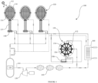
- FIG. 1 is a schematic diagram illustrating the solar turbine system according to an embodiment of the present invention.
- FIG 1 illustrates a solar turbine system 100 according to an embodiment of the present invention.
- the system 100 includes an energy collecting module 110, a high-pressure cylinder 120, a turbine 130, asymmetric bi-conical expansion chambers 140, a vector cancelling condenser 150, a condensation chamber 160, a control system (not shown in figure), a monitoring system (not shown in figure), a backup energy storage system (not shown in figure), and a generator (not shown in figure).
- the energy collecting module 110 is configured to receive solar radiation energy and convert a phase change material into gas.
- the energy collecting module 110 includes a transparent outer body 112 and a transparent inner body 114 separated by a vacuum.
- a 3-dimensional metallic grid 116 is placed inside the transparent inner body 114.
- the energy collecting module 110 further comprises an inlet pipe 118 fluidically coupled with the vector cancelling condenser 150 and the condensation chamber 150 to provide fluidized phase change material to the transparent inner body 114.
- An outlet pipe 119 fluidically coupled with the high-pressure cylinder 120 delivers the pressurized gas of the phase change material from the transparent inner body 114 to the high-pressure cylinder 120.
- the high-pressure cylinder 120 stores the gas at high pressure and supplies it to the turbine 130.
- the turbine 130 is coupled to the generator and generates electricity from the expansion of the gas received from the high-pressure cylinder 120.
- the asymmetric bi-conical expansion chambers 140 cool the gas from the turbine 130 and enhance heat dissipation using cooling fins or heat sinks.
- the vector cancelling condenser 150 partially condenses the gas into the fluid form of the phase change material and delivers the fluid back to the energy collecting module 110.
- the vector cancelling condenser 150 includes a body 152 defined by at least one wall and an enclosed space.
- the vector cancelling condenser 150 further comprises at least one pair of delivery tubes 154 with gas outlets 156 facing each other, canceling the velocity of gas to form saturated vapor.
- the vector cancelling condenser 150 also includes a fluid container 158 for storing the condensed fluid.
- the fluid container 158 is thermally insulated to reduce heat loss.
- the condensation chamber 160 receives the un-condensed gas from the vector cancelling condenser 150 and further condenses it into fluid form. The fluid is then delivered to the energy collecting module 110.
- the control system regulates the flow of the phase change material and the gas within the system based on temperature, pressure, and electricity generation requirements.
- the monitoring system collects and analyzes performance data of the solar turbine system 100.
- the backup energy storage system stores excess electricity generated by the turbine 130 for use during periods of low solar radiation.
- the phase change material used in the solar turbine system 100 can be selected from the group consisting of nitrogen, paraffin wax, fatty acids, and salts. The combination of these components and their interactions enable the efficient conversion of solar radiation energy into electricity, as well as the storage of excess energy.
- the present invention also encompasses a method for operating the solar turbine system described above.
- the method includes the following steps:
- the present invention also includes a computer-readable medium containing instructions for controlling the solar turbine system.
- the instructions comprise receiving solar radiation energy and converting a phase change material into gas, storing the gas at high pressure, expanding the gas to generate electricity, cooling the gas, partially condensing the gas into fluid form, condensing un-condensed gas into fluid, and delivering the fluid to the energy collecting module.
- the solar turbine system described in this patent specification provides an efficient and effective solution for converting solar radiation energy into electricity.
- the unique combination of components including the energy collecting module, high-pressure cylinder, turbine, asymmetric bi-conical expansion chambers, vector cancelling condenser, and condensation chamber, allows for improved heat dissipation, condensation of the working fluid, and overall system efficiency.
- the system's control system, backup energy storage, and monitoring capabilities further enhance its functionality and performance.
- the embodiments described above provide a solar turbine system and a method for efficiently converting solar radiation energy into electricity and enabling energy storage using phase change materials.
- the various components and features of the system work together to enhance performance and maximize energy conversion efficiency.
- the system is also equipped with control, monitoring, and backup energy storage capabilities to optimize operation and provide reliable power generation.
Landscapes
- Engineering & Computer Science (AREA)
- Chemical & Material Sciences (AREA)
- Combustion & Propulsion (AREA)
- Sustainable Development (AREA)
- Sustainable Energy (AREA)
- Life Sciences & Earth Sciences (AREA)
- Mechanical Engineering (AREA)
- General Engineering & Computer Science (AREA)
- Physics & Mathematics (AREA)
- Thermal Sciences (AREA)
- Power Engineering (AREA)
- High Energy & Nuclear Physics (AREA)
- Engine Equipment That Uses Special Cycles (AREA)
Abstract
A solar turbine system that utilizes solar radiation energy to generate electricity. The system comprises an energy collecting module, high-pressure cylinder, an asymmetric bi-conical expansion chamber, a vector cancelling condenser, a condensation chamber. The energy collecting module consists of a transparent outer body, a transparent inner body separated by a vacuum, and a 3-dimensional metallic grid. The vector cancelling condenser includes gas outlets facing each other to cancel gas velocity and form saturated vapor, which condenses to fluid.
Description
- The present invention relates to solar turbine systems, and more specifically, to a solar turbine system that utilizes phase change materials and incorporates various components to enhance efficiency and energy conversion.
- Solar energy is a renewable and abundant source of power. Various systems have been developed to harness solar energy for electricity generation. Solar turbine systems are one such approach, where solar radiation energy is collected and utilized to generate electricity through the expansion of a working fluid. However, existing solar turbine systems often suffer from low efficiency and limited energy storage capabilities. There is a need for an improved solar turbine system that maximizes energy conversion efficiency, enables energy storage, and enhances overall system performance.
- Further, existing solar turbine systems suffer from various drawbacks, including inefficiency in energy collection, limited cooling capabilities, and incomplete condensation of the expanded gas.
- Therefore, there is a need for an improved solar turbine system that overcomes the limitations of existing systems and provides enhanced energy collection, cooling, and condensation capabilities.
- The present invention provides a solar turbine system that overcomes the limitations of the prior art. The system incorporates various components, including an energy collecting module, a high-pressure cylinder, a turbine, asymmetric bi-conical expansion chambers, a vector cancelling condenser, and a condensation chamber. These components work together to efficiently convert solar radiation energy into electricity and enable energy storage using phase change materials.
- The present invention is directed to a solar turbine system that overcomes the limitations of existing systems. The system comprises several components, including an energy collecting module, a high-pressure cylinder, a turbine, asymmetric bi-conical expansion chambers, a vector cancelling condenser, and a condensation chamber. These components work together to efficiently convert solar radiation energy into electricity.
- The energy collecting module receives solar radiation energy and utilizes it to convert a fluid of a phase change material into gas. The high-pressure cylinder is fluidically coupled with the energy collecting module and stores the gas at high pressure. The turbine, fluidically coupled with the high-pressure cylinder, generates electricity from the expansion of the gas. The asymmetric bi-conical expansion chambers are fluidically coupled with the turbine and cool the gas received from the turbine. The vector cancelling condenser is fluidically coupled with one asymmetric bi-conical chamber and partially condenses the gas into the fluid form of the phase change material, delivering it back to the energy collecting module. The condensation chamber is fluidically coupled with the vector cancelling condenser and further condenses un-condensed gas into fluid, delivering it to the energy collecting module.
- In one embodiment, the energy collecting module includes a transparent outer body, a transparent inner body separated from the outer body by a vacuum, a 3-dimensional metallic grid placed inside the transparent inner body, an inlet pipe fluidically coupled with the vector cancelling condenser and condensation chamber, and an outlet pipe fluidically coupled with the high-pressure cylinder. The inlet pipe provides fluidized phase change material from the vector cancelling condenser and condensation chamber to the transparent inner body, while the outlet pipe delivers the pressurized gas of the phase change material from the transparent inner body to the high-pressure cylinder.
- The vector cancelling condenser comprises a body defined by at least one wall and an enclosed space. It further includes at least one pair of delivery tubes with gas outlets facing each other. These delivery tubes cancel the velocity of gas coming out from the gas outlets, forming saturated vapor of the gas. The latent heat of condensation from the saturated vapors releases to form condensed fluid, which is stored in a fluid container fluidically coupled with the body. The fluid container is thermally insulated to reduce heat loss from the stored condensed fluid.
- The solar turbine system may also include a control system to regulate the flow of the phase change material and gas based on temperature, pressure, and electricity generation requirements. Additionally, a backup energy storage system may be incorporated to store excess electricity generated by the turbine for use during periods of low solar radiation. The system may further comprise a monitoring system for collecting and analyzing performance data.
- The phase change material used in the system can be selected from a group consisting of nitrogen, cryogenic liquids, refrigerants, paraffinn wax, fatty acids, and salts. The turbine is coupled to a generator for converting mechanical energy into electrical energy. The asymmetric bi-conical expansion chamber may include cooling fins or heat sinks to enhance heat dissipation from the gas. The inlet pipe of the energy collecting module may have a flow control valve to regulate the flow of the fluidized phase change material.
- The invention also encompasses a method for operating the solar turbine system. The method involves receiving solar radiation energy, converting a phase change material into gas, storing the gas at high pressure, generating electricity by expanding the gas in a turbine, cooling the gas using asymmetric bi-conical expansion chambers, partially condensing the gas into the fluid form of the phase change material using a vector cancelling condenser, and further condensing un-condensed gas into fluid using a condensation chamber.
- Furthermore, the invention encompasses a computer-readable medium containing instructions for controlling the solar turbine system, where the instructions include steps for receiving solar radiation energy, converting a phase change material into gas, storing the gas at high pressure, expanding the gas to generate electricity, cooling the gas, partially condensing the gas into fluid form, condensing un-condensed gas into fluid, and delivering the fluid to the energy collecting module.
- In summary, the present invention provides a solar turbine system that efficiently converts solar radiation energy into electricity, enables energy storage using phase change materials, and incorporates various components to enhance system performance.
- To further clarify the above and other advantages and features of the present invention, a more particular description of the invention will be rendered by reference to specific embodiments thereof, which are illustrated in the accompanying drawings. It is appreciated that these drawings depict only typical embodiments of the invention and are therefore not to be considered limiting of its scope. The invention will be described and explained with additional specificity and detail through the use of the accompanying drawings, in which:
Figure 1 is a schematic diagram illustrating the solar turbine system according to an embodiment of the present invention. - The following detailed description of the invention refers to the accompanying drawings that illustrate specific embodiments in which the invention can be practiced. The embodiments are described in sufficient detail to enable those skilled in the art to practice the invention. It is to be understood that other embodiments may be utilized, and structural, functional, and procedural changes may be made without departing from the scope of the present invention.
-
Figure 1 illustrates asolar turbine system 100 according to an embodiment of the present invention. Thesystem 100 includes anenergy collecting module 110, a high-pressure cylinder 120, aturbine 130, asymmetricbi-conical expansion chambers 140, avector cancelling condenser 150, acondensation chamber 160, a control system (not shown in figure), a monitoring system (not shown in figure), a backup energy storage system (not shown in figure), and a generator (not shown in figure). - The
energy collecting module 110 is configured to receive solar radiation energy and convert a phase change material into gas. Theenergy collecting module 110 includes a transparentouter body 112 and a transparentinner body 114 separated by a vacuum. A 3-dimensionalmetallic grid 116 is placed inside the transparentinner body 114. Theenergy collecting module 110 further comprises aninlet pipe 118 fluidically coupled with thevector cancelling condenser 150 and thecondensation chamber 150 to provide fluidized phase change material to the transparentinner body 114. Anoutlet pipe 119 fluidically coupled with the high-pressure cylinder 120 delivers the pressurized gas of the phase change material from the transparentinner body 114 to the high-pressure cylinder 120. - The high-
pressure cylinder 120 stores the gas at high pressure and supplies it to theturbine 130. Theturbine 130 is coupled to the generator and generates electricity from the expansion of the gas received from the high-pressure cylinder 120. The asymmetricbi-conical expansion chambers 140 cool the gas from theturbine 130 and enhance heat dissipation using cooling fins or heat sinks. Thevector cancelling condenser 150 partially condenses the gas into the fluid form of the phase change material and delivers the fluid back to the energy collectingmodule 110. Thevector cancelling condenser 150 includes abody 152 defined by at least one wall and an enclosed space. Thevector cancelling condenser 150 further comprises at least one pair ofdelivery tubes 154 withgas outlets 156 facing each other, canceling the velocity of gas to form saturated vapor. Latent heat of condensation is released from the saturated vapors, resulting in the formation of condensed fluid. Thevector cancelling condenser 150 also includes afluid container 158 for storing the condensed fluid. Thefluid container 158 is thermally insulated to reduce heat loss. - The
condensation chamber 160 receives the un-condensed gas from thevector cancelling condenser 150 and further condenses it into fluid form. The fluid is then delivered to theenergy collecting module 110. The control system regulates the flow of the phase change material and the gas within the system based on temperature, pressure, and electricity generation requirements. The monitoring system collects and analyzes performance data of thesolar turbine system 100. The backup energy storage system stores excess electricity generated by theturbine 130 for use during periods of low solar radiation. - The phase change material used in the
solar turbine system 100 can be selected from the group consisting of nitrogen, paraffin wax, fatty acids, and salts. The combination of these components and their interactions enable the efficient conversion of solar radiation energy into electricity, as well as the storage of excess energy. - The present invention also encompasses a method for operating the solar turbine system described above. The method includes the following steps:
- a) Receiving solar radiation energy using the energy collecting module.
- b) Converting a phase change material into gas using the solar radiation energy received in step (a).
- c) Storing the gas at high pressure in the high-pressure cylinder fluidically coupled with the energy collecting module.
- d) Generating electricity by expanding the gas received from the high-pressure cylinder in the turbine.
- e) Cooling the gas received from the turbine using at least one asymmetric bi-conical expansion chamber fluidically coupled with the turbine.
- f) Partially condensing the gas received from the asymmetric bi-conical chamber into the fluid form of the phase change material using the vector cancelling condenser fluidically coupled with the asymmetric bi-conical chamber, and delivering the fluid to the energy collecting module.
- g) Further condensing the un-condensed gas from the vector cancelling condenser into fluid form using the condensation chamber fluidically coupled with the vector cancelling condenser, and delivering the fluid to the energy collecting module.
- In addition to the method of operating the solar turbine system, the present invention also includes a computer-readable medium containing instructions for controlling the solar turbine system. The instructions comprise receiving solar radiation energy and converting a phase change material into gas, storing the gas at high pressure, expanding the gas to generate electricity, cooling the gas, partially condensing the gas into fluid form, condensing un-condensed gas into fluid, and delivering the fluid to the energy collecting module.
- The solar turbine system described in this patent specification provides an efficient and effective solution for converting solar radiation energy into electricity. The unique combination of components, including the energy collecting module, high-pressure cylinder, turbine, asymmetric bi-conical expansion chambers, vector cancelling condenser, and condensation chamber, allows for improved heat dissipation, condensation of the working fluid, and overall system efficiency. The system's control system, backup energy storage, and monitoring capabilities further enhance its functionality and performance.
- The embodiments described above provide a solar turbine system and a method for efficiently converting solar radiation energy into electricity and enabling energy storage using phase change materials. The various components and features of the system work together to enhance performance and maximize energy conversion efficiency. The system is also equipped with control, monitoring, and backup energy storage capabilities to optimize operation and provide reliable power generation.
-
100 - Solar turbine system 110 - Energy collecting module 112 - Transparent outer body 114 - Transparent inner body 116 - 3-dimensional metallic grid 118 - Inlet pipe 119 - Outlet pipe 120 - High-pressure cylinder 130 - Turbine 140 - Asymmetric bi-conical expansion chamber 150 - Vector cancelling condenser 152 - Body 154 - Delivery tube 156 - Gas outlet 158 - Fluid container 160 - Condensation chamber
Claims (14)
- A solar turbine system comprising:an energy collecting module configured to receive solar radiation energy and utilize that solar radiation energy to convert a fluid of a phase change material into gas;a high-pressure cylinder fluidically coupled with the energy collecting module, and the high-pressure cylinder is configured to store the gas at high pressure;a turbine fluidically coupled with the high-pressure cylinder and the turbine is configured to generate electricity from the expansion of gas received from the high-pressure cylinder;at least one asymmetric bi-conical expansion chamber fluidically coupled with the turbine and the asymmetric bi-conical expansion chamber is configured to cool the gas received from the turbine;a vector cancelling condenser fluidically coupled with one asymmetric biconical chamber and the vector cancelling condenser is configured to partially condense the gas received from the asymmetric biconical chamber into fluid form of the phase change material and deliver the fluid to energy collecting module; anda condensation chamber fluidically coupled with the vector cancelling condenser and the condensation chamber is configured to receive un-condensed gas from the vector cancelling condenser and condense it to fluid and deliver the fluid to the energy collecting module.
- The solar turbine system as claimed in claim 1, wherein the energy collecting module further comprises:a transparent outer body;a transparent inner body separated from the outer body by a vacuum;a 3-dimensional metallic grid placed inside the transparent inner body;an inlet pipe fluidically coupled with the vector cancelling condenser and condensation chamber, the inlet pipe configured to provide fluidized phase change material from the vector cancelling condenser and condensation chamber to the transparent inner body;andan outlet pipe fluidically coupled with the high-pressure cylinder, the outlet pipe configured to deliver the pressurized gas of the phase change material from the transparent inner body to the high-pressure cylinder.
- The solar turbine system as claimed in claim 1, wherein the vector cancelling condenser comprises:a body defined by at least one wall and an enclosed space;at least one pair of delivery tubes having a pair of gas outlets in the body, wherein the pair of gas outlets are facing each other and configured to cancel the velocity of gas coming out from the gas outlets to form saturated vapor of the gas, and condensed fluid is formed by releasing latent heat of condensation from the saturated vapors;a fluid container fluidically coupled with the body, the fluid container configured to store the condensed fluid.
- The solar turbine system as claimed in claim 3, wherein the fluid container is thermally insulated to reduce heat loss from the stored condensed fluid.
- The solar turbine system as claimed in claim 1, further comprising a control system configured to regulate the flow of the phase change material and the gas within the system based on temperature, pressure, and electricity generation requirements.
- The solar turbine system as claimed in claim 1, wherein the phase change material is selected from the group consisting of nitrogen, paraffin wax, fatty acids, and salts.
- The solar turbine system as claimed in claim 1, wherein the turbine is coupled to a generator for converting mechanical energy into electrical energy.
- The solar turbine system as claimed in claim 1, wherein the asymmetric bi-conical expansion chamber comprises cooling fins or heat sinks to enhance heat dissipation from the gas.
- The solar turbine system as claimed in claim 1, further comprising a monitoring system for collecting and analyzing performance data of the system.
- The solar turbine system as claimed in claim 1, further comprising a backup energy storage system to store excess electricity generated by the turbine for use during periods of low solar radiation.
- The solar turbine system as claimed in claim 1, wherein the inlet pipe further comprises a flow control valve to regulate the flow of the fluidized phase change material to the transparent inner body.
- A method for operating a solar turbine system comprising:a) receiving solar radiation energy using an energy collecting module;b) converting a fluid of a phase change material into gas using the solar radiation energy received in step (a);c) storing the gas at high pressure in a high-pressure cylinder fluidically coupled with the energy collecting module;d) generating electricity by expanding the gas received from the high-pressure cylinder in a turbine;e) cooling the gas received from the turbine using at least one asymmetric bi-conical expansion chamber fluidically coupled with the turbine;f) partially condensing the gas received from the asymmetric bi-conical chamber into the fluid form of the phase change material using a vector cancelling condenser fluidically coupled with the asymmetric bi-conical chamber, and delivering the fluid to the energy collecting module;g) further condensing the un-condensed gas from the vector cancelling condenser into fluid form using a condensation chamber fluidically coupled with the vector cancelling condenser, and delivering the fluid to the energy collecting module.
- The method as claimed in claim 12, wherein the step of cooling the gas received from the turbine in the asymmetric bi-conical expansion chamber comprises utilizing the expansion of the gas to reduce its temperature.
- A computer-readable medium containing instructions for controlling a solar turbine system, the instructions comprising: receiving solar radiation energy and converting a phase change material into gas; storing the gas at high pressure; expanding the gas to generate electricity; cooling the gas; partially condensing the gas into fluid form; condensing un-condensed gas into fluid; and delivering the fluid to the energy collecting module.
Applications Claiming Priority (1)
| Application Number | Priority Date | Filing Date | Title |
|---|---|---|---|
| GB2310645.3A GB2631737A (en) | 2023-07-11 | 2023-07-11 | A solar turbine system and a method thereof |
Publications (1)
| Publication Number | Publication Date |
|---|---|
| EP4491871A1 true EP4491871A1 (en) | 2025-01-15 |
Family
ID=91898301
Family Applications (1)
| Application Number | Title | Priority Date | Filing Date |
|---|---|---|---|
| EP24187241.5A Pending EP4491871A1 (en) | 2023-07-11 | 2024-07-08 | A solar turbine system and a method thereof |
Country Status (3)
| Country | Link |
|---|---|
| US (1) | US12614951B2 (en) |
| EP (1) | EP4491871A1 (en) |
| GB (1) | GB2631737A (en) |
Citations (5)
| Publication number | Priority date | Publication date | Assignee | Title |
|---|---|---|---|---|
| US20050126170A1 (en) * | 2003-12-10 | 2005-06-16 | The Boeing Company | Solar power system and method for power generation |
| WO2007046855A2 (en) * | 2005-10-23 | 2007-04-26 | Wen-Show Ou | Method of generating power from naturally occurring heat |
| EP1890035A2 (en) * | 2006-08-04 | 2008-02-20 | Solucar, Investigacion Y Desarrollo (Solucar R&D), S.A. | Solar Concentrator plant |
| US20120167873A1 (en) * | 2009-07-08 | 2012-07-05 | Areva Solar, Inc. | Solar powered heating system for working fluid |
| US20120291433A1 (en) * | 2011-05-19 | 2012-11-22 | Ning Meng | Low temperature rankine cycle solar power system with low critical temperature hfc or hc working fluid |
Family Cites Families (2)
| Publication number | Priority date | Publication date | Assignee | Title |
|---|---|---|---|---|
| GB2606249B (en) * | 2022-01-12 | 2023-10-25 | Pravinchandra Budhdeo Shamir | Energy harnessing system and associated method |
| GB2630762B (en) * | 2023-06-06 | 2026-04-22 | Entropy Engines Ltd | A vector cancelling compressor device and a method thereof |
-
2023
- 2023-07-11 GB GB2310645.3A patent/GB2631737A/en active Pending
-
2024
- 2024-07-05 US US18/764,431 patent/US12614951B2/en active Active
- 2024-07-08 EP EP24187241.5A patent/EP4491871A1/en active Pending
Patent Citations (5)
| Publication number | Priority date | Publication date | Assignee | Title |
|---|---|---|---|---|
| US20050126170A1 (en) * | 2003-12-10 | 2005-06-16 | The Boeing Company | Solar power system and method for power generation |
| WO2007046855A2 (en) * | 2005-10-23 | 2007-04-26 | Wen-Show Ou | Method of generating power from naturally occurring heat |
| EP1890035A2 (en) * | 2006-08-04 | 2008-02-20 | Solucar, Investigacion Y Desarrollo (Solucar R&D), S.A. | Solar Concentrator plant |
| US20120167873A1 (en) * | 2009-07-08 | 2012-07-05 | Areva Solar, Inc. | Solar powered heating system for working fluid |
| US20120291433A1 (en) * | 2011-05-19 | 2012-11-22 | Ning Meng | Low temperature rankine cycle solar power system with low critical temperature hfc or hc working fluid |
Also Published As
| Publication number | Publication date |
|---|---|
| US12614951B2 (en) | 2026-04-28 |
| GB2631737A (en) | 2025-01-15 |
| US20250023424A1 (en) | 2025-01-16 |
Similar Documents
| Publication | Publication Date | Title |
|---|---|---|
| AU2008228211B2 (en) | Method and device for intermediate superheating in solar direct evaporation in a solar-thermal power plant | |
| CN101842557B (en) | Method and device for converting thermal energy of a low temperature heat source into mechanical energy | |
| AU2004267168B2 (en) | Method for increasing the efficiency of a gas turbine system, and gas turbine system suitable therefor | |
| US20090288695A1 (en) | Hybrid Solar Power Generator | |
| AU2007251575B2 (en) | Conversion of heat into mechanical energy by means of a jet compressor | |
| JP6302481B2 (en) | Concentrating solar power plant and method | |
| EP2574755A2 (en) | System and method for generating electric power | |
| JP3391515B2 (en) | Apparatus and method for obtaining power from high pressure geothermal fluid | |
| EP3728801B1 (en) | Bottoming cycle power system | |
| CN104185717B (en) | System and method for recovering waste heat from dual heat sources | |
| US5974804A (en) | Apparatus and method for converting thermal energy to mechanical energy | |
| US20150075210A1 (en) | Method for charging and discharging a heat accumulator and plant for storing and releasing thermal energy, suitable for this method | |
| CN114934825B (en) | Carbon dioxide energy storage system and method coupled with coal motor group | |
| CN115118017A (en) | Open type liquid carbon dioxide energy storage system | |
| KR20100097148A (en) | Vapor compression and expansion air conditioner | |
| US5469705A (en) | Heat recovery in a liquid ring pump seal liquid chiller system | |
| RU2425987C1 (en) | Method of power plant operation | |
| WO2009045117A2 (en) | A method of utilising low- and medium-temperature heat sources and media and a system for utilising low- and medium-temperature heat sources and media | |
| JP2016540913A (en) | Power generator with gear-integrated steam compressor | |
| US12614951B2 (en) | Solar turbine system and a method thereof | |
| EP2275650A1 (en) | Combined cycle power plant | |
| WO2021240534A1 (en) | A subcritical carbon dioxide rankine cycle for power generation | |
| CN114198159A (en) | Thermal power generating unit steam heat storage and LNG cold energy combined peak regulation system and use method | |
| JP2002122006A (en) | Power generation equipment utilizing low-temperature exhaust heat | |
| JP5976570B2 (en) | Superheated steam generator |
Legal Events
| Date | Code | Title | Description |
|---|---|---|---|
| PUAI | Public reference made under article 153(3) epc to a published international application that has entered the european phase |
Free format text: ORIGINAL CODE: 0009012 |
|
| STAA | Information on the status of an ep patent application or granted ep patent |
Free format text: STATUS: REQUEST FOR EXAMINATION WAS MADE |
|
| 17P | Request for examination filed |
Effective date: 20240708 |
|
| AK | Designated contracting states |
Kind code of ref document: A1 Designated state(s): AL AT BE BG CH CY CZ DE DK EE ES FI FR GB GR HR HU IE IS IT LI LT LU LV MC ME MK MT NL NO PL PT RO RS SE SI SK SM TR |