EP4491867A1 - Electromagnetic valve mechanism and fuel pump - Google Patents
Electromagnetic valve mechanism and fuel pump Download PDFInfo
- Publication number
- EP4491867A1 EP4491867A1 EP22945723.9A EP22945723A EP4491867A1 EP 4491867 A1 EP4491867 A1 EP 4491867A1 EP 22945723 A EP22945723 A EP 22945723A EP 4491867 A1 EP4491867 A1 EP 4491867A1
- Authority
- EP
- European Patent Office
- Prior art keywords
- recess
- fixed core
- fuel
- rod
- valve mechanism
- Prior art date
- Legal status (The legal status is an assumption and is not a legal conclusion. Google has not performed a legal analysis and makes no representation as to the accuracy of the status listed.)
- Pending
Links
Images








Classifications
-
- F—MECHANICAL ENGINEERING; LIGHTING; HEATING; WEAPONS; BLASTING
- F02—COMBUSTION ENGINES; HOT-GAS OR COMBUSTION-PRODUCT ENGINE PLANTS
- F02M—SUPPLYING COMBUSTION ENGINES IN GENERAL WITH COMBUSTIBLE MIXTURES OR CONSTITUENTS THEREOF
- F02M59/00—Pumps specially adapted for fuel-injection and not provided for in groups F02M39/00 -F02M57/00, e.g. rotary cylinder-block type of pumps
- F02M59/20—Varying fuel delivery in quantity or timing
- F02M59/36—Varying fuel delivery in quantity or timing by variably-timed valves controlling fuel passages to pumping elements or overflow passages
- F02M59/366—Valves being actuated electrically
- F02M59/368—Pump inlet valves being closed when actuated
-
- F—MECHANICAL ENGINEERING; LIGHTING; HEATING; WEAPONS; BLASTING
- F02—COMBUSTION ENGINES; HOT-GAS OR COMBUSTION-PRODUCT ENGINE PLANTS
- F02M—SUPPLYING COMBUSTION ENGINES IN GENERAL WITH COMBUSTIBLE MIXTURES OR CONSTITUENTS THEREOF
- F02M59/00—Pumps specially adapted for fuel-injection and not provided for in groups F02M39/00 -F02M57/00, e.g. rotary cylinder-block type of pumps
- F02M59/02—Pumps specially adapted for fuel-injection and not provided for in groups F02M39/00 -F02M57/00, e.g. rotary cylinder-block type of pumps of reciprocating-piston or reciprocating-cylinder type
- F02M59/025—Pumps specially adapted for fuel-injection and not provided for in groups F02M39/00 -F02M57/00, e.g. rotary cylinder-block type of pumps of reciprocating-piston or reciprocating-cylinder type characterised by a single piston
- F02M59/027—Unit-pumps, i.e. single piston and cylinder pump-units, e.g. for cooperating with a camshaft
-
- F—MECHANICAL ENGINEERING; LIGHTING; HEATING; WEAPONS; BLASTING
- F02—COMBUSTION ENGINES; HOT-GAS OR COMBUSTION-PRODUCT ENGINE PLANTS
- F02M—SUPPLYING COMBUSTION ENGINES IN GENERAL WITH COMBUSTIBLE MIXTURES OR CONSTITUENTS THEREOF
- F02M59/00—Pumps specially adapted for fuel-injection and not provided for in groups F02M39/00 -F02M57/00, e.g. rotary cylinder-block type of pumps
- F02M59/44—Details, components parts, or accessories not provided for in, or of interest apart from, the apparatus of groups F02M59/02 - F02M59/42; Pumps having transducers, e.g. to measure displacement of pump rack or piston
- F02M59/46—Valves
- F02M59/466—Electrically operated valves, e.g. using electromagnetic or piezoelectric operating means
-
- F—MECHANICAL ENGINEERING; LIGHTING; HEATING; WEAPONS; BLASTING
- F02—COMBUSTION ENGINES; HOT-GAS OR COMBUSTION-PRODUCT ENGINE PLANTS
- F02M—SUPPLYING COMBUSTION ENGINES IN GENERAL WITH COMBUSTIBLE MIXTURES OR CONSTITUENTS THEREOF
- F02M2200/00—Details of fuel-injection apparatus, not otherwise provided for
- F02M2200/04—Fuel-injection apparatus having means for avoiding effect of cavitation, e.g. erosion
Definitions
- the present invention relates to a solenoid valve mechanism and a fuel pump including the solenoid valve mechanism.
- a solenoid valve mechanism of a fuel pump is described in, for example, PTL 1.
- a rubber material is press-fitted into a housing part formed in a fixed core.
- the rubber material buffers impact caused by cavitation collapse that occurs in the fixed core. As a result, the occurrence of cavitation and erosion is suppressed.
- the housing part of the fixed core made of a metal material is filled with a fuel. For this reason, cavitation and erosion cannot be suppressed in the housing part of the fixed core as a whole.
- an object of the present invention is to provide a solenoid valve mechanism and a fuel pump that can suppress cavitation and erosion that occur in a fixed core.
- a solenoid valve mechanism of the present invention includes: a valve; a rod engaged with the valve; a movable core engaged with the rod; a fixed core that generates a magnetic attractive force between the fixed core and the movable core; and a rod biasing spring that biases the rod in the direction of separating the rod away from the fixed core.
- the fixed core includes: a first recess having a bottom surface with which one end of the rod biasing spring comes in contact; a second recess formed on the bottom surface of the first recess; and an elastic member housed in the second recess. The elastic member covers the whole of an inner wall surface of the second recess.
- a fuel pump of the present invention include: a body provided with a pressurized chamber; a plunger supported by the body in such a way as to be capable of reciprocation, the plunger increasing and decreasing a capacity of the pressurized chamber by the reciprocation; and the solenoid valve mechanism that discharges a fuel to the pressurized chamber.
- FIG. 1 is an overall configuration diagram of a fuel supply system using a high-pressure fuel supply pump according to the present embodiment of the present invention.
- the fuel supply system includes a high-pressure fuel supply pump (fuel pump) 100, an engine control unit (ECU) 101, a fuel tank 103, a common rail 106, and a plurality of injectors 107.
- the components of the high-pressure fuel supply pump 100 are incorporated integrally into a pump body 1(Hereinafter, "body 1".).
- a fuel in the fuel tank 103 is pumped up by a feed pump 102 that is driven based on a signal from the ECU 101.
- the pumped up fuel is pressurized by a pressure regulator (not illustrated) into the fuel with a proper pressure, which is sent through a low-pressure pipe 104 to a low-pressure fuel suction inlet 51 of the high-pressure fuel supply pump 100.
- the high-pressure fuel supply pump 100 pressurizes the fuel supplied from the fuel tank 103 and pressure-transfers the fuel to the common rail 106.
- the common rail 106 is fitted with the plurality of injectors 107 and with a fuel pressure sensor 105.
- the plurality of injectors 107 are fitted such that the number of the injectors matches the number of cylinders (combustion chambers).
- the plurality of injectors 107 inject the fuel according to a drive current outputted from the ECU 101.
- the fuel supply system of this embodiment is a so-called direct injection engine system in which the injectors 107 inject the fuel directly into cylinders of an engine.
- the fuel pressure sensor 105 outputs detected pressure data to the ECU 101. Based on engine status data (e.g., a crank rotation angle, a throttle opening degree, an engine rotating speed, a fuel pressure, etc.), the ECU 101 calculates a proper fuel injection amount (target fuel injection length), a proper fuel pressure (target fuel pressure), or the like.
- engine status data e.g., a crank rotation angle, a throttle opening degree, an engine rotating speed, a fuel pressure, etc.
- the ECU 101 calculates a proper fuel injection amount (target fuel injection length), a proper fuel pressure (target fuel pressure), or the like.
- the ECU 101 controls driving of the high-pressure fuel supply pump 100 and the plurality of injectors 107.
- the ECU 101 includes a pump control unit that controls the high-pressure fuel supply pump 100, and an injector control unit that controls the injectors 107.
- the high-pressure fuel supply pump 100 includes a pressure pulsation reducing mechanism 9, a solenoid suction valve mechanism (solenoid valve mechanism) 3 that is a variable capacity mechanism, a relief valve mechanism 4 (see FIG. 2 ), and a discharge valve mechanism 8.
- the fuel flowing in through the low-pressure fuel suction inlet 51 flows through the pressure pulsation reducing mechanism 9 and a suction pass 10b and finally reaches a suction port 31b of the solenoid suction valve mechanism 3.
- the fuel having flown into the solenoid suction valve mechanism 3 passes through a suction valve 32, flows through a suction pass 1a formed on the body 1, and then flows into a pressurized chamber 11.
- a plunger 2 is held in such a way as to be capable of reciprocating.
- power from a cam 91 (see FIG. 2 ) of the engine is transmitted, which causes the plunger 2 to reciprocate.
- the fuel is sucked in from the solenoid suction valve mechanism 3 in a moving down stroke of the plunger 2, whereas the fuel is pressurized in an moving up stroke of the plunger 2.
- the discharge valve mechanism 8 opens, and the high-pressure fuel is pressure-transferred through a fuel discharge opening 12a to the common rail 106.
- Fuel discharge by the high-pressure fuel supply pump 100 is adjusted by opening/closing of the solenoid suction valve mechanism 3. Opening/closing of the solenoid suction valve mechanism 3 is then controlled by the ECU 101.
- a configuration of the high-pressure fuel supply pump 100 will then be described with reference to FIGS. 2 to 4 .
- FIG. 2 is a vertical sectional view of the high-pressure fuel supply pump 100.
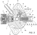
- FIG. 3 is a horizontal sectional view of the high-pressure fuel supply pump 100, showing a section perpendicular to the vertical direction of high-pressure fuel supply pump 100.
- FIG. 4 is a vertical sectional view of the high-pressure fuel supply pump 100, the vertical sectional view being seen from a direction different from a direction in which the vertical sectional view of FIG. 2 is seen.
- the body 1 of the high-pressure fuel supply pump 100 is provided with the above suction pass 1a and a mounting flange 1b (see FIG. 3 ).
- the mounting flange 1b is attached closely to a fuel pump mounting portion 90 of the engine (internal combustion engine).
- the mounting flange 1b is fixed to the fuel pump mounting portion 90, using a plurality of bolts or screws (not illustrated).
- the high-pressure fuel supply pump 100 is fixed to the fuel pump mounting portion 90 via the mounting flange 1b.
- an O-ring 93 which is a specific example of a seat member, is interposed between the fuel pump mounting portion 90 and the body 1. This O-ring 93 prevents engine oil from flowing through between the fuel pump mounting portion 90 and the body 1 and leaking out of the engine (internal combustion engine).
- a cylinder 6 is fitted, which guides the reciprocation of the plunger 2.
- the cylinder 6 is of a cylindrical shape.
- the outer periphery of the cylinder 6 is press-fitted in a cylinder housing recess formed on the body 1.
- the body 1 has a fixing part 1c engaged with a central part in the axial direction of the cylinder 6.
- the fixing part 1c of the body 1 pushes the cylinder 6 upward (the upper side in FIG. 2 ). This prevents the fuel pressurized in the pressurized chamber 11 from leaking from a gap between an upper end surface of the cylinder 6 and the body 1.
- a lower end of the plunger 2 is provided with a tappet 92.
- the tappet 92 converts the rotational movement of a cam 91 attached to a cam shaft of the engine into a vertical movement and transmits the vertical movement to the plunger 2.
- the plunger 2 is biased toward the cam 91 by a spring 16 via a retainer 15.
- the lower end of the plunger 2 is thus press-fitted to the tappet 92.
- the tappet 92 reciprocates as a result of rotation of the cam 91.
- the plunger 2 reciprocates together with the tappet 92 to change the capacity of the pressurized chamber 11.
- a seal holder 17 is disposed between the cylinder 6 and the retainer 15.
- the seal holder 17 is of a cylindrical shape into which the plunger 2 is inserted. Between an upper part of the seal holder 17 and the pump body 1, an auxiliary chamber 17a is formed.
- the seal holder 17 holds a plunger seal 18 on its lower end closer to the retainer 15.
- the plunger seal 18 is slidably in contact with the outer periphery of the plunger 2. When the plunger 2 reciprocates, the plunger seal 18 seals up the auxiliary chamber 17a to prevent the fuel in the auxiliary chamber 17a from flowing into the engine. The plunger seal 18 also prevents lubricating oil (including engine oil) lubricating sliding parts in the engine from flowing into the body 1.
- the plunger 2 reciprocates in the vertical direction.
- the capacity of the pressurized chamber 11 increases.
- the capacity of the pressurized chamber 11 decreases.
- the plunger 2 is disposed in such a way as to reciprocate in the direction of increasing and decreasing the capacity of the pressurized chamber 11.
- the plunger 2 has a large diameter part 2a and a small diameter part 2b.
- the large diameter part 2a and the small diameter part 2b are in the auxiliary chamber 17a.
- the volume of the auxiliary chamber 17a is, therefore, increased or decreased by the reciprocation of the plunger 2.
- the auxiliary chamber 17a communicates with a low-pressure fuel chamber 10 through a fuel pass 10c (see FIG. 3 ).
- a fuel pass 10c see FIG. 3 .
- the plunger 2 moves down, it creates a flow of the fuel from the auxiliary chamber 17a to the low-pressure fuel chamber 10.
- the plunger 2 moves up, it creates a flow of the fuel from the low-pressure fuel chamber 10 to the auxiliary chamber 17a. Because of these processes, a flow rate of the fuel pumped in and out by the pump can be reduced in a suction stroke or a return stroke of the high-pressure fuel supply pump 100. As a result, pressure pulsation that develops in the high-pressure fuel supply pump 100 can be reduced.
- a suction joint 5 is fitted to the side of the body 1.
- the suction joint 5 is connected to a low-pressure pipe 104 (see FIG. 1 ) through which the fuel supplied from the fuel tank 103 flows.
- the fuel in the fuel tank 103 is supplied from the suction joint 5 into the high-pressure fuel supply pump 100.
- the suction joint 5 includes a low-pressure fuel suction inlet 51 connected to the low-pressure pipe 104 and a suction channel 52 communicating with the low-pressure fuel suction inlet 51.
- a suction filter 53 is placed in a fuel pass communicating with the suction channel 52.
- the suction filter 53 removes foreign matter from the fuel and prevents entry of foreign matter in the high-pressure fuel supply pump 100.
- the fuel having passed through the suction channel 52 flows through the pressure pulsation reducing mechanism 9 and the suction pass 10b (see FIG. 2 ), which are provided in the low-pressure fuel chamber 10, and reaches the suction port 31b (see FIG. 2 ) of the solenoid suction valve mechanism 3.
- the body 1 of the high-pressure fuel supply pump 100 is provided with the low-pressure fuel chamber 10.
- the low-pressure fuel chamber 10 is covered with a damper cover 14.
- the low-pressure fuel chamber 10 is provided with a low-pressure fuel channel 10a and the suction pass 10b.
- the suction pass 10b communicates with a suction port 31b (see FIG. 2 ) of the solenoid suction valve mechanism 3.
- the fuel having flown through the low-pressure fuel channel 10a further flows through the suction pass 10b to reach the suction port 31b of the solenoid suction valve mechanism 3.
- the low-pressure fuel channel 10a is provided with the pressure pulsation reducing mechanism 9.
- the pressure pulsation reducing mechanism 9 reduces spread of the pressure pulsation having occurred in the high-pressure fuel supply pump 100 to the low-pressure pipe 104.
- the pressure pulsation reducing mechanism 9 has a metal diaphragm damper constructed by pasting together two corrugated-plate-like metal discs on their outer peripheries. An inert gas, such as argon, is injected into the metal diaphragm damper. The metal diaphragm damper expands and contracts to absorb or reduce pressure pulsation.
- An inert gas such as argon
- the discharge valve mechanism 8 is connected to the outlet side of the pressurized chamber 11.
- the discharge valve mechanism 8 is housed in a discharge valve chamber 1d formed in the body 1.
- the discharge valve mechanism 8 includes a discharge valve seat member 81, and a discharge valve 82 that comes into contact with and separates from the discharge valve seat member 81.
- the discharge valve mechanism 8 includes a discharge valve spring 83 that biases the discharge valve 82 toward the discharge valve seat member 81, and a discharge valve stopper 84 that determines an amount of lift (movement distance) of the discharge valve 82.
- the discharge valve stopper 84 and the body 1 are welled together at a contact part 85.
- the discharge valve chamber 1d is a substantially columnar space extending horizontally. One end of the discharge valve chamber 1d communicates with the pressurized chamber 11. The other end of the discharge valve chamber 1d is open on the side of the body 1. The opening on the other end of the discharge valve chamber 1d is sealed by the discharge valve stopper 84.
- a discharge joint 12 is welded by a welding part 12b.
- the discharge joint 12 has a fuel discharge opening 12a.
- the fuel discharge opening 12a communicates with the discharge valve chamber 1d via a discharge pass 1f.
- the discharge pass 1f extends horizontally inside the body 1.
- the fuel discharge opening 12a is connected to the common rail 106 (see FIG. 1 ).
- the discharge valve 82 In a state where a fuel pressure in the pressurized chamber 11 is lower than a fuel pressure in the discharge valve chamber 1d, the discharge valve 82 is brought into pressure contact with the discharge valve seat member 81 because of a pressure difference acting on the discharge valve 82 and a biasing force applied by the discharge valve spring 83. This puts the discharge valve mechanism 8 in a closed-valve state.
- the discharge valve 82 separates from the discharge valve seat member 81. This puts the discharge valve mechanism 8 in an open-valve state.
- the discharge valve mechanism 8 When the discharge valve mechanism 8 is put in the open-valve state, the fuel is discharged from the pressurized chamber 11 and flows through the discharge valve chamber 1d, the discharge pass 1f, and the fuel discharge opening 12a of the discharge joint 12 to reach the common rail 106 (see FIG. 1 ).
- the discharge valve mechanism 8 functions as a check valve that limits the direction of flow of the fuel.
- the body 1 is provided with a relief valve mechanism 4 communicating with the pressurized chamber 11.
- the relief valve mechanism 4 includes a relief spring 41, a relief valve holder 42, a relief valve 43, a seat member 44, and a spring support member 45.
- the seat member 44 is of a bottomed cylindrical shape.
- the seat member 44 holds therein the relief spring 41, the relief valve holder 42, the relief valve 43, and the support member 45.
- the support member 45 is disposed closer to the pressurized chamber 11.
- the bottom of the seat member 44 is located opposite to the pressurized chamber 11.
- the bottom of the seat member 44 has a through-hole serving as a fuel pass.
- One end of the relief spring 41 is in contact with the spring support member 45.
- the other end portion of the relief spring 41 is in contact with the relief valve holder 42.
- the relief spring 41 biases the relief valve holder 42 toward the bottom of the seat member 44.
- the relief valve 43 is disposed between the relief valve holder 42 and the bottom of the seat member 44.
- the relief valve 43 is engaged with the relief valve holder 42.
- the relief valve 43 together with the relief valve holder 42, is biased toward the bottom of the seat member 44.
- the relief valve 43 thus closes the fuel pass of the seat member 44.
- the fuel pass of the seat member 44 communicates with the discharge pass 1f (see FIG. 3 ). Fuel transfer between the pressurized chamber 11 (upstream side) and the seat member 44 (downstream side) is cut off by the relief valve 43 kept in contact with (firmly stuck to) the seat member 44.
- the configuration of the relief valve mechanism 4 is not limited to this case.
- the relief valve mechanism according to the present invention may communicate with, for example, a low-pressure pass (the low-pressure fuel suction inlet 51, the suction pass 10b, or the like).
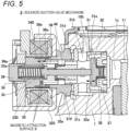
- FIG. 5 is an enlarged vertical sectional view of the solenoid suction valve mechanism 3 of the high-pressure fuel supply pump 100, showing the open-valve state of the solenoid suction valve mechanism 3.
- the solenoid suction valve mechanism 3 is inserted into a lateral hole formed in the body 1.
- the solenoid suction valve mechanism 3 includes a suction valve seat 31 press-fitted in the lateral hole formed on the body 1, a suction valve 32, a rod 33, a rod biasing spring 34, an electromagnetic coil 35, and an anchor 36.
- the suction valve 32 is a specific example of a valve according to the present invention.
- the anchor 36 is a specific example of a movable core according to the present invention.
- the suction valve seat 31 is of a cylindrical shape.
- the inner periphery of the suction valve seat 31 is provided with a seating part 31a.
- a suction port 31b is formed, which extends from the inner periphery to the outer periphery.
- the suction port 31b communicates with the suction pass 10b in the above-described low-pressure fuel chamber 10.
- the suction valve seat 31 has a rod guide 31c through which the rod 33 penetrates.
- the rod guide 31c is of a cylindrical shape.
- the rod guide 31c has a communication pass 31d penetrating it in the axial direction. Because of this configuration, when the anchor 36 moves in the axial direction, the anchor 36 does not hamper the movement of the fuel in the solenoid suction valve mechanism 3.
- a stopper 37 is placed, which is counter to the seating part 31a of the suction valve seat 31.
- the suction valve 32 is disposed between the stopper 37 and the seating part 31a.
- a valve biasing spring 38 is interposed between the stopper 37 and the suction valve 32.
- the valve biasing spring 38 biases the suction valve 32 toward the seating part 31a.
- the suction valve 32 By coming in contact with the seating part 31a, the suction valve 32 closes a communication portion between the suction port 31b and the pressurized chamber 11. This puts the solenoid suction valve mechanism 3 in the closed-valve state.
- the suction valve 32 By coming in contact with the stopper 37, on the other hand, the suction valve 32 opens the communication portion between the suction port 31b and the pressurized chamber 11. This puts the solenoid suction valve mechanism 3 in the open-valve state.
- the rod 33 penetrates the rod guide 31c of the suction valve seat 31 and the anchor 36.
- the rod 33 has a rod flange 33a formed thereon.
- the rod flange 33a is engaged with one end of the rod biasing spring 34.
- the other end of the rod biasing spring 34 is engaged with a fixed core 39 surrounding the rod biasing spring 34.
- the rod biasing spring 34 biases the suction valve 32 in a valve-open direction, i.e., toward the stopper 37 via the rod 33.
- the anchor 36 is formed in a substantially cylindrical shape. In addition to a cylindrical hole through which the rod 33 penetrates, the anchor 36 has a communication pass 36a penetrating it in the axial direction. Because of this configuration, when the anchor 36 moves in the axial direction, the anchor 36 does not hamper the movement of the fuel in the solenoid suction valve mechanism 3.
- one end of the anchor biasing spring 40 is in contact.
- the other end in the axial direction of the anchor 36 is counter to an end surface of the fixed core 39.
- a flange contact part is formed, with which the rod flange 33a of the rod 33 comes in contact.
- the other end of the anchor biasing spring 40 is in contact with a rod guide 31c.
- the anchor biasing spring 40 biases the anchor 36 toward the rod flange 33a of the rod 33.
- a movement allowed distance 36e of the anchor 36 is set longer than a movement allowed distance 32e of the suction valve 32. This allows the suction valve 32 to certainly come in contact with (to certainly sit on) the seating part 31a. As a result, the solenoid suction valve mechanism 3 can be certainly put in the closed-valve state.
- the fixed core 39 is of a bottomed cylindrical shape.
- the fixed core 39 has a recess extending in the axial direction.
- the rod biasing spring 34 is inserted in the recess of the fixed core 39. With the bottom surface of the recess of the fixed core 39, the other end of the rod biasing spring 34 is in contact.
- the recess of the fixed core 39 will be described later with reference to FIG. 11 .
- an outer core 310 is connected to the opening of the lateral hole formed in the body 1.
- the outer core 310 is of a substantially cylindrical shape.
- the outer periphery of one end in the axial direction of the outer core 310 is fitted into the lateral hole formed on the body 1.
- the outer core 310 is fixed to the body 1 by welding.
- the anchor 36 With the inner periphery of the outer core 310, the anchor 36 is slidably engaged. In other words, the anchor 36 is guided by the inner periphery of the outer core 310 and moves in the axial direction (open-valve direction and closed-valve direction). The other end in the axial direction of the outer core 310 projects from the body 1. On the outer periphery of the other end in the axial direction of the outer core 310, a first yoke 320 is fitted. The outer core 310 is press-fitted and fixed in the first yoke 320.
- the first yoke 320 is of a bottomed cylindrical shape surrounding an electromagnetic coil 35.
- the fixed core 39 projects from the opening side of the first yoke 320.
- a fitting hole is formed for fitting the first yoke 320 on the outer core 310.
- the opening of the first yoke 320 is closed with a second yoke 330.
- the second yoke 330 is a substantially annular plate material. Almost at the center of the second yoke 330, a circular through-hole is formed.
- the fixed core 39 penetrates the through-hole of the second yoke 330.
- a part of fixed core 39 that projects from the second yoke 330 has a fixing pin 39a fixed to the part.
- the fixing pin 39a biases the second yoke 330 toward the anchor 36.
- the first yoke 320 and the second yoke 330 jointly make up a magnetic circuit.
- the second yoke 330 is made of the same material as the first yoke 320 is made of.
- a magnetic stainless steel may be used as the material of the first yoke 320 and the second yoke 330.
- the electromagnetic coil 35 is disposed inside the first yoke 320 in such a way as to make a circle around the fixed core 39.
- the electromagnetic coil 35 is formed of a copper wire wound around a bobbin 35a multiple times.
- the terminal member 30 (see FIG. 2 ) is electrically connected.
- the electromagnetic coil 35 carries a flow of current supplied through the terminal member 30.
- the rod 33 In a non-energized state where the electromagnetic coil 35 carries no current flow, the rod 33 is biased in the open-valve direction by the rod biasing spring 34, thus pushing the suction valve 32 in the open-valve direction. As a result, the suction valve 32 separates from the seating part 31a and comes in contact with the stopper 37, which puts the solenoid suction valve mechanism 3 in the open-valve state.
- the solenoid suction valve mechanism 3 is a normal open type valve mechanism that opens in the non-energized state.
- the terminal member 30 is disposed in a recess of the connector 30a (see FIG. 2 ).
- the connector 30a is molded integrally with the terminal member 30 and the electromagnetic coil 35.
- the connector 30a penetrates a cutout of the first yoke 320.
- a lower part of the connector 30a is counter to the second yoke 330.
- the second yoke 330 has a cutout for avoiding interference with the connector 30a.
- a sealing 340 is disposed on the inner peripheral side of the electromagnetic coil 35.
- the sealing 340 is of a cylindrical shape. In one end in the axial direction of the sealing 340, the outer core 310 is inserted. In the other end in the axial direction of the sealing 340, the fixed core 39 is inserted.
- Outer peripheral surfaces of the fixed core 39 and outer core 310 form a peripheral surface matching a peripheral surface of the sealing 340 when the fixed core 39 and outer core 310 are inserted in the sealing 340. This facilitates attachment of other components, such as the bobbin 35a.
- the sealing 340 is made of a material that is thin and that can be changed in shape (expanded and contracted).
- the sealing 340 has a larger elongation percentage than the fixed core 39 and the anchor 36.
- the sealing 340 has, for example, an elongation percentage of 350 or more.
- the sealing 340 is a non-magnetic material.
- As the material of the sealing 340 for example, an austenitic stainless steel is preferable.
- the fuel in the suction port 31b flows through between the suction valve 32 and the seating part 31a and further flows through a plurality of fuel passage hole (not shown) of the stopper 37 and the suction pass 1a to enter the pressurized chamber 11.
- the solenoid suction valve mechanism 3 is in the open-valve state, the suction valve 32 comes in contact with the stopper 37 and therefore the position of the suction valve 32 in the open-valve direction is regulated.
- a gap between the suction valve 32 and the seating part 31a is equivalent to the movement allowed distance 32e of the suction valve 32, which movement allowed distance 32e is an open-valve stroke.
- a current flow in the electromagnetic coil 35 generates magnetic flux.
- the generated magnetic flux passes through the fixed core 39, the second yoke 330, the first yoke 320, the outer core 310, and the anchor 36, which make up a magnetic path. Because of this, a magnetic attractive force acts on respective magnetic attraction surfaces S of the anchor 36 and the fixed core 39. As a result, the anchor 36 overcomes the biasing force of the rod biasing spring 34 to move against the direction of the biasing force and comes in contact with the fixed core 39.
- a stroke in which the plunger 2 moves down will be referred to as a suction stroke.
- the fuel in the pressurized chamber 11 is pressurized.
- the fuel in the pressurized chamber 11 is pressure-transferred through the discharge valve mechanism 8 to the common rail 106 (see FIG. 1 ).
- a stroke in which the plunger 2 moves up will be referred to as a compression stroke.
- the capacity of the pressurized chamber 11 increases, resulting in a drop in a fuel pressure in the pressurized chamber 11.
- the fuel pressure in the pressurized chamber 11 becomes lower than a fuel pressure in the suction port 31b.
- the suction valve 32 separates from the seating part 31a. This puts the solenoid suction valve mechanism 3 in the open-valve state.
- the fuel in the suction port 31b flows through between the suction valve 32 and the seating part 31a and further flows through the plurality of holes formed on the stopper 37 to enter the pressurized chamber 11.
- the compression stroke starts.
- the electromagnetic coil 35 remains in the non-energized state and therefore no magnetic attractive force acts between the anchor 36 and the fixed core 39.
- a biasing force in the open-valve direction is applied, the biasing force corresponding to a difference in biasing force between the anchor biasing spring 40 and the rod biasing spring 34.
- a fluid pressure pressure in the closed-valve direction
- the fluid pressure being generated when the fuel flows from the pressurized chamber 11 back to the low-pressure fuel channel 10a.
- the difference in biasing force between the anchor biasing spring 40 and the rod biasing spring 34 is set larger than the fluid pressure.
- the capacity of the pressurized chamber 11 decreases as the plunger 2 moves up. This causes the fuel sucked into the pressurized chamber 11 to flow through between the suction valve 32 and the suction valve seat 31 and reenters the suction port 31b. The fuel pressure in the pressurized chamber 11, therefore, does not rise. This stroke is referred to as a return stroke.
- the anchor 36 overcomes the biasing force of the rod biasing spring 34 and moves toward the fixed core 39 (in the valve-closed direction).
- the rod 33 engaged with the anchor 36 moves in the direction of separating away from the suction valve 32.
- the biasing force by the valve biasing spring 38 and the fluid pressure by the fuel flowing into the suction pass 10b force the suction valve 32 to sit on the seating part 31a.
- the solenoid suction valve mechanism 3 is put in the closed-valve state.
- the fuel in the pressurized chamber 11 is pressurized as the plunger 2 moves up.
- the pressure to the fuel rises to a given pressure or higher pressure
- the fuel is discharged from the pressurized chamber 11 to flow through the discharge valve mechanism 8 into the common rail 106 (see FIG. 1 ).
- This process is referred to as a discharge process.
- the compression stroke in which the plunger 2 moves from a bottom dead center to a top dead center is made up of the return stroke and the discharge stroke.
- Advancing timing of supplying current to the electromagnetic coil 35 reduces the ratio of the return stroke while increasing the ratio of the discharge stroke during the compression stroke.
- the fuel returned to the suction pass 10b decreases as the fuel discharged under high pressure increases.
- Delaying timing of supplying current to the electromagnetic coil 35 increases the ratio of the return stroke while reducing the ratio of the discharge stroke during the compression stroke.
- the fuel returned to the suction pass 10b increases as the fuel discharged under high pressure decreases.
- the amount of the fuel discharged under high pressure can be adjusted to an amount the engine (internal combustion engine) needs.
- FIG. 6A depicts a state in which the fixed core 39 and the anchor 36 are separated from each other.
- FIG. 6B depicts a moment at which the anchor 36 comes in contact with the fixed core 39.
- FIG. 7A depicts a state in which the anchor 36 is in contact with the fixed core 39 and cavitation occurs.
- FIG. 7B is depicts a state in which erosion occurs.
- a fluid (fuel) present between the anchor 36 and the fixed core 39 flows into the communication pass 36a of the anchor 36 and into the recess of the fixed core 39 (hereinafter, the recess of the fixed core 39 will be referred to as "fixed core recess").
- the recess of the fixed core 39 will be referred to as "fixed core recess"
- an area V near the bottom surface of the fixed core recess provides no place for the fluid to escape.
- the fuel in the area V is highly pressurized.
- the anchor 36 moves in the direction of approaching the fixed core 39 and collides with the fixed core 39.
- the anchor 36 thus stops moving and becomes in a state of in contact with the fixed core 39.
- the pressure of the fluid in the area V recovers. This happens because of a pressure wave that is created when the fluid flowing out of the fixed core recess collides with a nearby component and is reflected by it or reentry of the fluid into the fixed core recess caused by a drop in the pressure of the fluid in the fixed core recess.
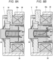
- FIG. 8A depicts a state in which the fixed core 39 and the anchor 36 are in contact with each other.
- FIG. 8B depicts a state in which the anchor 36 is in the middle of a process of separating away from the fixed core 39.
- FIG. 9A depicts a state in which cavitation occurs when the anchor 36 is in the middle of process of separating away from the fixed core 39.
- FIG. 9B depicts a state in which erosion occurs.
- the pressure of the fluid in the area V recovers. This happens because of a pressure wave created by stoppage of the moving anchor 36 or reentry of the fluid into the fixed core recess caused by a drop in the pressure of the fluid in the fixed core recess.
- the area V of the fixed core recess is under a severe environment where the risk of cavitation and erosion gets higher as the moving speed of the anchor 36 gets higher.
- a high-pressure fuel pump offering a higher discharge pressure and a higher flow rate is in demand. Meeting this demand requires an increase in the amount of lift of the cam 91.
- the moving speed of the anchor 36 is qualitatively correlated with the amount of lift of the cam 91. Therefore, to meet the demand for a high-pressure fuel pump offering a higher discharge pressure and a higher flow rate, it is necessary to improve robustness against cavitation and erosion in the area V of the fixed core recess.
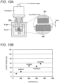
- FIG. 10 A is a conceptual diagram of a vibration-type cavitation test device.
- FIG. 10B is a diagram of a test result by the vibration-type cavitation test device.
- the vibration-type cavitation test device vibrates a horn 200 vertically to cause pressure fluctuations, thereby causing cavitation.
- a test piece 202 is set counter to a front end 201 of the horn 200.
- the vibration-type cavitation test device can check the progress of erosion resulting from cavitation of the test piece 202.
- a test result under certain test conditions is shown in a graph of 10B.
- the horizontal axis of the graph of FIG. 10B represents hardness (Vickers hardness), and the vertical axis of the graph of FIG. 10B represents a latent period preceding the occurrence of erosion.
- a material with hardness of Hv400 or more has a latent period of about 40 minutes to 60 minutes.
- a rubber material has a latent period of 120 minutes or more, which gives a confirmation that the rubber material has high erosion resistance.
- the rubber material does not possess hardness that can be expressed in Vickers hardness. Therefore, the latent period of the rubber material is not plotted on the graph of FIG. 10B .
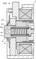
- a configuration of the fixed core 39 according to the first embodiment will then be described with reference to FIG. 11 .
- FIG. 11 is an enlarged vertical sectional view of the fixed core 39 according to the first embodiment.
- the fixed core 39 includes a fixed core body 391, and a rubber member 392 fitted to the fixed core body 391.
- the fixed core body 391, which is made of a metal material, is formed into a bottomed cylindrical shape.
- the fixed core body 391 has a first recess 391a, into which the rod biasing spring 34 is inserted, and a second recess 391b, which is opened to the bottom surface of the first recess 391a.
- the first recess 391a is of a substantially columnar shape. With the bottom surface of the first recess 391a, the other end of the above rod biasing spring 34 is in contact.
- the second recess 391b is open at the center of the bottom surface of the first recess 391a.
- the second recess 391b is counter to an axial hole of the rod biasing spring 34.
- the second recess 391b is of a substantially columnar shape.
- the rubber member 392 corresponds to an elastic member according to the present invention.
- the rubber member 392 is of a substantially columnar shape that is substantially the same in diameter as the second recess 391b.
- the rubber member 392 is press-fitted and fixed in the second recess 391b.
- the rubber member 392 covers the whole of an inner wall surface of the second recess 391b.
- the rubber member 392 is formed into the shape that is substantially the same as the second recess 391b. An end surface of rubber member 392 that is closer to the rod biasing spring 34 forms the same plane as the bottom surface of the first recess 391a forms.
- the rubber member 392 is of a shape that does not come in contact with the bottom surface of the first recess 391a. In other words, the rubber member 392 is not interposed between the bottom surface of the first recess 391a and the rod biasing spring 34.
- the rubber member 392 is provided with a recess 392a.
- the recess 392a is opened to the end surface of rubber member 392 that is closer to the rod biasing spring 34.
- the recess 392a is formed into a substantially egg shape in consideration of moldability of the rubber material.
- the fuel enters the first recess 391a of the fixed core body 391 and the recess 392a of the rubber member 392. The fuel, however, does not enter the second recess 391b of the fixed core body 391.
- the inner wall surface of the second recess 391b of the fixed core body 391 is not in contact with the fuel. This suppresses occurrence of erosion on the inner wall surface of the second recess 391b. In this manner, by fitting the rubber member 392 in the second recess 391b, occurrence of erosion in the fixed core body 391 made of the metal material can be suppressed.
- the bottom surface of the second recess 391b according to this embodiment is formed into a flat surface.
- the bottom surface of the second recess 391b according to the present invention may be formed into a curved surface or a tapered surface in consideration of easiness in processing.
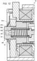
- a solenoid suction valve mechanism according to a second embodiment of the present invention will then be described with reference to FIG. 12 .
- FIG. 12 is an enlarged vertical sectional view of a fixed core according to the second embodiment.
- a solenoid suction valve mechanism 3A according to the second embodiment has a configuration similar to that of the solenoid suction valve mechanism 3 according to the first embodiment.
- the solenoid suction valve mechanism 3A is different from the solenoid suction valve mechanism 3 in that the solenoid suction valve mechanism 3A includes a fixed core 39A. Therefore, the fixed core 39A will be described, and description of the same configuration as that of the solenoid suction valve mechanism 3 will be omitted.
- the fixed core 39A includes the fixed core body 391, and a rubber member 393 fitted to the fixed core body 391.
- This fixed core body 391 is the same as the fixed core body 391 of the first embodiment.
- the rubber member 393 corresponds to the elastic member according to the present invention.
- the rubber member 393 is of a substantially columnar shape that is substantially the same in diameter as the second recess 391b.
- the rubber member 393 is press-fitted and fixed in the second recess 391b.
- the rubber member 393 covers the whole of the inner wall surface of the second recess 391b.
- the rubber member 393 is formed into the shape that is substantially the same as the second recess 391b. An end surface of rubber member 393 that is closer to the rod biasing spring 34 forms the same plane as the bottom surface of the first recess 391a forms.
- the rubber member 393 is of a shape that does not come in contact with the bottom surface of the first recess 391a. In other words, the rubber member 393 is not interposed between the bottom surface of the first recess 391a and the rod biasing spring 34.
- the rubber member 393 is provided with a recess 393a.
- the recess 393a is opened to the end surface of rubber member 392 that is closer to the rod biasing spring 34.
- the recess 393a is formed into a substantially columnar shape.
- the bottom surface of the recess 393a is formed into a hemispherical curved surface.
- a projection 393b projecting toward the opening is formed at the center of the bottom surface of the recess 393a.
- An end surface of the projection 393b is located in the recess 393a.
- the position of the projection 393b is set in consideration of a molding die for molding the rubber member 393 and a nozzle insertion position. In this manner, the rubber member according to the present invention is applicable when having the recess where cavitation and erosion concentrate, and the shape of the recess can be determined properly.
- the fuel enters the first recess 391a of the fixed core body 391 and the recess 393a of the rubber member 393.
- the fuel does not enter the second recess 391b of the fixed core body 391.
- cavitation and erosion concentrate in the recess 393a of the rubber member 393. Therefore, occurrence of cavitation and erosion in an area located closer to the rod biasing spring 34 (the first recess 391a) than the rubber member 393 can be suppressed.
- the inner wall surface of the second recess 391b of the fixed core body 391 is not in contact with the fuel. This suppresses occurrence of erosion on the inner wall surface of the second recess 391b. In this manner, by fitting the rubber member 393 in the second recess 391b, occurrence of erosion in the fixed core body 391 made of the metal material can be suppressed.
- a solenoid suction valve mechanism according to a third embodiment of the present invention will then be described with reference to FIG. 13 .
- FIG. 13 is an enlarged vertical sectional view of a fixed core according to the third embodiment.
- a solenoid suction valve mechanism 3B according to the third embodiment has a configuration similar to that of the solenoid suction valve mechanism 3 according to the first embodiment.
- the solenoid suction valve mechanism 3B is different from the solenoid suction valve mechanism 3 in that the solenoid suction valve mechanism 3B includes a fixed core 39B. Therefore, the fixed core 39B will be described, and description of the same configuration as that of the solenoid suction valve mechanism 3 will be omitted.
- the fixed core 39B includes a fixed core body 394, and a rubber member 395 fitted to the fixed core body 394.
- the fixed core body 394 which is made of a metal material, is formed into a bottomed cylindrical shape.
- the fixed core body 394 has a first recess 394a, into which the rod biasing spring 34 is inserted, and a second recess 394b, which is opened to the bottom surface of the first recess 394a, and a communication port 394c open to the bottom surface of the second recess 394b.
- the first recess 394a is of a substantially columnar shape. With the bottom surface of the first recess 394a, the other end of the above rod biasing spring 34 is in contact.
- the second recess 394b is open at the center of the bottom surface of the first recess 394a.
- the second recess 394b is counter to the axial hole of the rod biasing spring 34.
- the second recess 394b is of a substantially columnar shape.
- the communication port 394c extends to reach an end surface on the bottom side of the fixed core body 394.
- the rubber member 395 corresponds to the elastic member according to the present invention.
- the rubber member 395 is integrally molded (e.g., insert molding) with the fixed core body 394.
- the rubber material is injected from the communication port 394c toward the second recess 394b. This prevents a case where a nozzle that injects the rubber material and the fixed core body 394 interfere with each other. As a result, molding the rubber member 395 is made easy.
- the rubber member 395 fills the second recess 394b and the communication port 394c.
- the rubber member 395 therefore, covers the whole of an inner wall surface of the second recess 394b and of an inner wall surface of the communication port 394c.
- the rubber member 395 is formed into a shape substantially the same as the shape of the second recess 394b and the communication port 394c. An end surface of rubber member 395 that is closer to the rod biasing spring 34 forms the same plane as the bottom surface of the first recess 394a forms.
- the rubber member 395 is of a shape that does not come in contact with the bottom surface of the first recess 394a. In other words, the rubber member 395 is not interposed between the bottom surface of the first recess 394a and the rod biasing spring 34.
- the rubber member 395 is provided with a recess 395a.
- the recess 395a is opened to the end surface of rubber member 395 that is closer to the rod biasing spring 34.
- the recess 395a is formed into a substantially egg shape in consideration of moldability of the rubber material.
- the fuel enters the first recess 394a of the fixed core body 394 and the recess 395a of the rubber member 395. The fuel, however, does not enter the second recess 394b and the communication port 394c of the fixed core body 394.
- the inner wall surface of the second recess 394b of the fixed core body 394 is not in contact with the fuel. This suppresses occurrence of erosion on the inner wall surface of the second recess 394b. In this manner, by fitting the rubber member 395 in the second recess 394b, occurrence of erosion in the fixed core body 394 made of the metal material can be suppressed.
- a solenoid suction valve mechanism according to a fourth embodiment of the present invention will then be described with reference to FIG. 14 .
- FIG. 14 is an enlarged vertical sectional view of a fixed core according to the fourth embodiment.
- a solenoid suction valve mechanism 3C according to the fourth embodiment has a configuration similar to that of the solenoid suction valve mechanism 3 according to the first embodiment.
- the solenoid suction valve mechanism 3C is different from the solenoid suction valve mechanism 3 in that the solenoid suction valve mechanism 3C includes a fixed core 39C. Therefore, the fixed core 39C will be described, and description of the same configuration as that of the solenoid suction valve mechanism 3 will be omitted.
- the fixed core 39C includes a fixed core body 396, and a rubber member 397 fitted to the fixed core body 396.
- the fixed core body 396 which is made of a metal material, is formed into a bottomed cylindrical shape.
- the fixed core body 396 has a first recess 396a, into which the rod biasing spring 34 is inserted, and a second recess 396b, which is opened to the bottom surface of the first recess 396a, and a communication port 396c open to the bottom surface of the second recess 396b.
- the first recess 396a is of a substantially columnar shape. With the bottom surface of the first recess 396a, the other end of the above rod biasing spring 34 is in contact.
- the second recess 396b is open at the center of the bottom surface of the first recess 396a.
- the second recess 396b is counter to the axial hole of the rod biasing spring 34.
- the second recess 396b is of a substantially columnar shape.
- the communication port 396c extends to reach an end surface on the bottom side of the fixed core body 394.
- the communication port 396c is shaped such that two columns having different diameters are lined up in the axial direction.
- the communication port 396c has a large diameter part opened to the bottom side of the fixed core body 394, and a small diameter part communicating with the large diameter part and with the second recess 396b.
- the large diameter part is larger in diameter than the small diameter part.
- the rubber member 397 corresponds to the elastic member according to the present invention.
- the rubber member 397 is integrally molded (e.g., insert molding) with the fixed core body 396.
- the rubber material is injected from the communication port 396c toward the second recess 396b. This prevents a case where a nozzle that injects the rubber material and the fixed core body 394 interfere with each other. As a result, molding the rubber member 397 is made easy.
- the large diameter part on the inlet side of the communication port 396c (the side opposite to the second recess 396b) is a space larger than the small diameter part closer to the second recess 396b.
- the large diameter part thus accommodates nozzles of various sizes that inject the rubber material.
- the rubber member 397 fills the second recess 396b and the communication port 396c.
- the rubber member 397 therefore, covers the whole of an inner wall surface of the second recess 396b and of an inner wall surface of the communication port 396c.
- the rubber member 397 is formed into a shape that is substantially the same as the shape of the second recess 396b and communication port 396c. An end surface of rubber member 397 that is closer to the rod biasing spring 34 forms the same plane as the bottom surface of the first recess 396a forms.
- the rubber member 397 is of a shape that does not come in contact with the bottom surface of the first recess 396a. In other words, the rubber member 397 is not interposed between the bottom surface of the first recess 396a and the rod biasing spring 34.
- the rubber member 397 is provided with a recess 397a.
- the recess 397a is opened to the end surface of rubber member 397 that is closer to the rod biasing spring 34.
- the recess 397a is formed into a substantially egg shape in consideration of moldability of the rubber material.
- the fuel enters the first recess 396a of the fixed core body 396 and the recess 397a of the rubber member 397. The fuel, however, fuel does not enter the second recess 396b of the fixed core body 396 and the communication port 396c.
- the inner wall surface of the second recess 396b of the fixed core body 396 is not in contact with the fuel. This suppresses occurrence of erosion on the inner wall surface of the second recess 396b. In this manner, by fitting the rubber member 397 in the second recess 396b, occurrence of erosion in the fixed core body 396 made of the metal material can be suppressed.
- the above-described solenoid suction valve mechanism 3 (solenoid valve mechanism) includes the suction valve 32 (valve), the rod 33 engaged with the suction valve 32, and the anchor 36 (movable core) engaged with the rod 33.
- the solenoid suction valve mechanism 3 further includes the fixed core 39 that generates a magnetic attractive force between the fixed core 39 and the anchor 36, and the rod biasing spring 34 that biases the rod 33 in the direction of separating the rod 33 away from the fixed core 39.
- the fixed core 39 includes the first recess 391a having the bottom surface with which the one end of the rod biasing spring 34 comes in contact, the second recess 391b formed on the bottom surface of the first recess 391a, and the rubber member 392 (elastic member) housed in the second recess 391b.
- the rubber member 392 covers the whole of an inner wall surface of the second recess 391b.
- the rubber member 392 (elastic member) of the above-described solenoid suction valve mechanism 3 (solenoid valve mechanism) is provided with the recess 392a formed on a surface in contact with the fuel.
- the rubber member 392 (elastic member) of the above-described solenoid suction valve mechanism 3 may project in such a way as to be closer to the rod biasing spring 34 than the bottom surface of the first recess 391a.
- the rubber member 395 (elastic member) of the above-described solenoid suction valve mechanism 3B (solenoid valve mechanism) is filled into the second recess 394b and is fixed or bonded to the second recess 394b.
- the rubber member 395 covering the whole of the inner wall surface of the second recess 394b can be formed easily.
- the rubber member 392 (elastic member) of the above-described solenoid suction valve mechanism 3 is of the shape that is not in contact with the bottom surface of the first recess 391a.
- the rubber member 392 is not interposed between the bottom surface of the first recess 391a and the rod biasing spring 34. This prevents a case where the length of the rod biasing spring 34 in its compressed state is shorter than a set length. Hence the rod biasing spring 34 is able to bias the anchor 36 with a proper biasing force.
- the rubber member 392 (elastic member) of the above-described solenoid suction valve mechanism 3 is of the shape that is not interposed between the bottom surface of the first recess 391a and the rod biasing spring 34.
- the above-described high-pressure fuel supply pump 100 (fuel pump) includes the body 1 having the pressurized chamber 11, the plunger 2 that is supported by the body 1 in such a way as to be capable of reciprocation and that increases or decreases the capacity of the pressurized chamber 11 by the reciprocation, and the above-described solenoid suction valve mechanism 3 (solenoid valve mechanism) that discharges the fuel to the pressurized chamber 11.
- the rubber member 392 and 393 are each press-fitted and fixed in the second recess 391b.
- the rubber member (elastic member) according to the present invention may be bonded to the inner wall surface of the second recess, using an adhesive.
- the rubber members 392,393,395, and 397 are each used as the elastic member according to the present invention.
- the elastic member according to the present invention is not limited to the rubber member.
- An elastic member of a different material may be adopted properly, providing that the adopted elastic member can buffer shock waves caused by cavitation collapse.
- the elastic member according to the present invention for example, be a member having a Poisson's ratio of 0.45 or more and 0.55 or less.
Landscapes
- Engineering & Computer Science (AREA)
- Chemical & Material Sciences (AREA)
- Combustion & Propulsion (AREA)
- Mechanical Engineering (AREA)
- General Engineering & Computer Science (AREA)
- Physics & Mathematics (AREA)
- Electromagnetism (AREA)
- Fuel-Injection Apparatus (AREA)
Abstract
Description
- The present invention relates to a solenoid valve mechanism and a fuel pump including the solenoid valve mechanism.
- A solenoid valve mechanism of a fuel pump is described in, for example,
PTL 1. In the solenoid valve mechanism (solenoid mechanism) described inPTL 1, a rubber material is press-fitted into a housing part formed in a fixed core. The rubber material buffers impact caused by cavitation collapse that occurs in the fixed core. As a result, the occurrence of cavitation and erosion is suppressed. - PTL 1:
WO 2020/100398 A - However, in the solenoid valve mechanism described in
PTL 1, the housing part of the fixed core made of a metal material is filled with a fuel. For this reason, cavitation and erosion cannot be suppressed in the housing part of the fixed core as a whole. - In view of the above problem, an object of the present invention is to provide a solenoid valve mechanism and a fuel pump that can suppress cavitation and erosion that occur in a fixed core.
- In order to solve the above problem and achieve the object of the present invention, a solenoid valve mechanism of the present invention includes: a valve; a rod engaged with the valve; a movable core engaged with the rod; a fixed core that generates a magnetic attractive force between the fixed core and the movable core; and a rod biasing spring that biases the rod in the direction of separating the rod away from the fixed core. The fixed core includes: a first recess having a bottom surface with which one end of the rod biasing spring comes in contact; a second recess formed on the bottom surface of the first recess; and an elastic member housed in the second recess. The elastic member covers the whole of an inner wall surface of the second recess.
- A fuel pump of the present invention include: a body provided with a pressurized chamber; a plunger supported by the body in such a way as to be capable of reciprocation, the plunger increasing and decreasing a capacity of the pressurized chamber by the reciprocation; and the solenoid valve mechanism that discharges a fuel to the pressurized chamber.
- According to the solenoid valve mechanism and the fuel pump configured in the above manner, cavitation and erosion that occur in a fixed core can be suppressed.
- Problems, configurations, and effects other than those described above will be made clear by the following description of embodiments.
-
- [
FIG. 1] FIG. 1 is an overall configuration diagram of a fuel supply system using a high-pressure fuel supply pump according to a first embodiment of the present invention. - [
FIG. 2] FIG. 2 is a vertical sectional view of the high-pressure fuel supply pump according to the first embodiment of the present invention. - [
FIG. 3] FIG. 3 is a horizontal sectional view of the high-pressure fuel supply pump according to the first embodiment of the present invention, the horizontal sectional view being seen from above. - [
FIG. 4] FIG. 4 is a vertical sectional view of the high-pressure fuel supply pump according to the first embodiment of the present invention, the vertical sectional view being seen from a direction different from a direction in which the vertical sectional view ofFIG. 2 is seen. - [
FIG. 5] FIG. 5 is a vertical sectional view of a solenoid valve mechanism according to the first embodiment of the present invention. - [
FIG. 6] FIGS. 6A and 6B depict a mechanism by which cavitation and erosion occur in a recess of a fixed core when the fixed core and a movable core come in contact with each other. - [
FIG. 7] FIGS. 7A and 7B depict the mechanism by which cavitation and erosion occur in the recess of the fixed core when the fixed core and the movable core come in contact with each other. - [
FIG. 8] FIGS. 8A and 8B depict a mechanism by which cavitation and erosion occur in the recess of the fixed core when the fixed core and the movable core separate away from each other. - [
FIG. 9] FIGS. 9A and 9B depict the mechanism by which cavitation and erosion occur in the recess of the fixed core when the fixed core and the movable core separate away from each other. - [
FIG. 10] FIGS. 10A and 10B depict a conceptual view of a vibration-type cavitation test device and a test result, respectively. - [
FIG. 11] FIG. 11 is an enlarged vertical view of the fixed core of the solenoid valve mechanism according to the first embodiment of the present invention. - [
FIG. 12] FIG. 12 is an enlarged vertical view of a fixed core of a solenoid valve mechanism according to a second embodiment of the present invention. - [
FIG. 13] FIG. 13 is an enlarged vertical view of a fixed core of a solenoid valve mechanism according to a third embodiment of the present invention. - [
FIG. 14] FIG. 14 is an enlarged vertical view of a fixed core of a solenoid valve mechanism according to a fourth embodiment of the present invention. - Hereinafter, a solenoid valve mechanism and a high-pressure fuel supply pump according to a first embodiment of the present invention will be described. In the drawings, the same members are denoted by the same reference signs.
- First, a fuel supply system using a high-pressure fuel supply pump (fuel pump) according to the present embodiment will be described with reference to
FIG. 1 . -
FIG. 1 is an overall configuration diagram of a fuel supply system using a high-pressure fuel supply pump according to the present embodiment of the present invention. - As shown in
FIG. 1 , the fuel supply system includes a high-pressure fuel supply pump (fuel pump) 100, an engine control unit (ECU) 101, afuel tank 103, acommon rail 106, and a plurality ofinjectors 107. The components of the high-pressurefuel supply pump 100 are incorporated integrally into a pump body 1(Hereinafter, "body 1".). - A fuel in the
fuel tank 103 is pumped up by afeed pump 102 that is driven based on a signal from the ECU 101. The pumped up fuel is pressurized by a pressure regulator (not illustrated) into the fuel with a proper pressure, which is sent through a low-pressure pipe 104 to a low-pressurefuel suction inlet 51 of the high-pressurefuel supply pump 100. - The high-pressure
fuel supply pump 100 pressurizes the fuel supplied from thefuel tank 103 and pressure-transfers the fuel to thecommon rail 106. Thecommon rail 106 is fitted with the plurality ofinjectors 107 and with afuel pressure sensor 105. - The plurality of
injectors 107 are fitted such that the number of the injectors matches the number of cylinders (combustion chambers). The plurality ofinjectors 107 inject the fuel according to a drive current outputted from theECU 101. The fuel supply system of this embodiment is a so-called direct injection engine system in which theinjectors 107 inject the fuel directly into cylinders of an engine. - The
fuel pressure sensor 105 outputs detected pressure data to theECU 101. Based on engine status data (e.g., a crank rotation angle, a throttle opening degree, an engine rotating speed, a fuel pressure, etc.), the ECU 101 calculates a proper fuel injection amount (target fuel injection length), a proper fuel pressure (target fuel pressure), or the like. - Based on a result of calculation of the fuel pressure (target fuel pressure) or the like, the ECU 101 controls driving of the high-pressure
fuel supply pump 100 and the plurality ofinjectors 107. Specifically, the ECU 101 includes a pump control unit that controls the high-pressurefuel supply pump 100, and an injector control unit that controls theinjectors 107. - The high-pressure
fuel supply pump 100 includes a pressurepulsation reducing mechanism 9, a solenoid suction valve mechanism (solenoid valve mechanism) 3 that is a variable capacity mechanism, a relief valve mechanism 4 (seeFIG. 2 ), and adischarge valve mechanism 8. The fuel flowing in through the low-pressurefuel suction inlet 51 flows through the pressurepulsation reducing mechanism 9 and asuction pass 10b and finally reaches asuction port 31b of the solenoidsuction valve mechanism 3. - The fuel having flown into the solenoid
suction valve mechanism 3 passes through asuction valve 32, flows through asuction pass 1a formed on thebody 1, and then flows into a pressurizedchamber 11. In the pressurizedchamber 11, aplunger 2 is held in such a way as to be capable of reciprocating. To theplunger 2, power from a cam 91 (seeFIG. 2 ) of the engine is transmitted, which causes theplunger 2 to reciprocate. - In the
pressurized chamber 11, the fuel is sucked in from the solenoidsuction valve mechanism 3 in a moving down stroke of theplunger 2, whereas the fuel is pressurized in an moving up stroke of theplunger 2. When a fuel pressure in thepressurized chamber 11 exceeds a given value, thedischarge valve mechanism 8 opens, and the high-pressure fuel is pressure-transferred through a fuel discharge opening 12a to thecommon rail 106. Fuel discharge by the high-pressurefuel supply pump 100 is adjusted by opening/closing of the solenoidsuction valve mechanism 3. Opening/closing of the solenoidsuction valve mechanism 3 is then controlled by theECU 101. - A configuration of the high-pressure
fuel supply pump 100 will then be described with reference toFIGS. 2 to 4 . -
FIG. 2 is a vertical sectional view of the high-pressurefuel supply pump 100.FIG. 3 is a horizontal sectional view of the high-pressurefuel supply pump 100, showing a section perpendicular to the vertical direction of high-pressurefuel supply pump 100.FIG. 4 is a vertical sectional view of the high-pressurefuel supply pump 100, the vertical sectional view being seen from a direction different from a direction in which the vertical sectional view ofFIG. 2 is seen. - As shown in
FIGS. 2 and3 , thebody 1 of the high-pressurefuel supply pump 100 is provided with theabove suction pass 1a and a mountingflange 1b (seeFIG. 3 ). The mountingflange 1b is attached closely to a fuelpump mounting portion 90 of the engine (internal combustion engine). The mountingflange 1b is fixed to the fuelpump mounting portion 90, using a plurality of bolts or screws (not illustrated). In other words, the high-pressurefuel supply pump 100 is fixed to the fuelpump mounting portion 90 via the mountingflange 1b. - As shown in
FIGS. 2 and4 , an O-ring 93, which is a specific example of a seat member, is interposed between the fuelpump mounting portion 90 and thebody 1. This O-ring 93 prevents engine oil from flowing through between the fuelpump mounting portion 90 and thebody 1 and leaking out of the engine (internal combustion engine). - To the
body 1 of the high-pressurefuel supply pump 100, acylinder 6 is fitted, which guides the reciprocation of theplunger 2. Thecylinder 6 is of a cylindrical shape. The outer periphery of thecylinder 6 is press-fitted in a cylinder housing recess formed on thebody 1. Thebody 1 and thecylinder 6, together with the solenoidsuction valve mechanism 3, theplunger 2, and the discharge valve mechanism 8 (seeFIG. 3 ), form thepressurized chamber 11. - The
body 1 has a fixingpart 1c engaged with a central part in the axial direction of thecylinder 6. The fixingpart 1c of thebody 1 pushes thecylinder 6 upward (the upper side inFIG. 2 ). This prevents the fuel pressurized in thepressurized chamber 11 from leaking from a gap between an upper end surface of thecylinder 6 and thebody 1. - A lower end of the
plunger 2 is provided with atappet 92. Thetappet 92 converts the rotational movement of acam 91 attached to a cam shaft of the engine into a vertical movement and transmits the vertical movement to theplunger 2. Theplunger 2 is biased toward thecam 91 by aspring 16 via aretainer 15. The lower end of theplunger 2 is thus press-fitted to thetappet 92. Thetappet 92 reciprocates as a result of rotation of thecam 91. Theplunger 2 reciprocates together with thetappet 92 to change the capacity of thepressurized chamber 11. - A
seal holder 17 is disposed between thecylinder 6 and theretainer 15. Theseal holder 17 is of a cylindrical shape into which theplunger 2 is inserted. Between an upper part of theseal holder 17 and thepump body 1, anauxiliary chamber 17a is formed. Theseal holder 17 holds aplunger seal 18 on its lower end closer to theretainer 15. - The
plunger seal 18 is slidably in contact with the outer periphery of theplunger 2. When theplunger 2 reciprocates, theplunger seal 18 seals up theauxiliary chamber 17a to prevent the fuel in theauxiliary chamber 17a from flowing into the engine. Theplunger seal 18 also prevents lubricating oil (including engine oil) lubricating sliding parts in the engine from flowing into thebody 1. - In
FIG. 2 , theplunger 2 reciprocates in the vertical direction. When theplunger 2 moves down, the capacity of thepressurized chamber 11 increases. When theplunger 2 moves up, the capacity of thepressurized chamber 11 decreases. In this manner, theplunger 2 is disposed in such a way as to reciprocate in the direction of increasing and decreasing the capacity of thepressurized chamber 11. - The
plunger 2 has alarge diameter part 2a and asmall diameter part 2b. When theplunger 2 reciprocates, thelarge diameter part 2a and thesmall diameter part 2b are in theauxiliary chamber 17a. The volume of theauxiliary chamber 17a is, therefore, increased or decreased by the reciprocation of theplunger 2. - The
auxiliary chamber 17a communicates with a low-pressure fuel chamber 10 through afuel pass 10c (seeFIG. 3 ). When theplunger 2 moves down, it creates a flow of the fuel from theauxiliary chamber 17a to the low-pressure fuel chamber 10. When theplunger 2 moves up, it creates a flow of the fuel from the low-pressure fuel chamber 10 to theauxiliary chamber 17a. Because of these processes, a flow rate of the fuel pumped in and out by the pump can be reduced in a suction stroke or a return stroke of the high-pressurefuel supply pump 100. As a result, pressure pulsation that develops in the high-pressurefuel supply pump 100 can be reduced. - As shown in
FIGS. 3 and4 , asuction joint 5 is fitted to the side of thebody 1. Thesuction joint 5 is connected to a low-pressure pipe 104 (seeFIG. 1 ) through which the fuel supplied from thefuel tank 103 flows. The fuel in thefuel tank 103 is supplied from the suction joint 5 into the high-pressurefuel supply pump 100. - The
suction joint 5 includes a low-pressurefuel suction inlet 51 connected to the low-pressure pipe 104 and asuction channel 52 communicating with the low-pressurefuel suction inlet 51. As shown inFIG. 4 , asuction filter 53 is placed in a fuel pass communicating with thesuction channel 52. Thesuction filter 53 removes foreign matter from the fuel and prevents entry of foreign matter in the high-pressurefuel supply pump 100. The fuel having passed through thesuction channel 52 flows through the pressurepulsation reducing mechanism 9 and thesuction pass 10b (seeFIG. 2 ), which are provided in the low-pressure fuel chamber 10, and reaches thesuction port 31b (seeFIG. 2 ) of the solenoidsuction valve mechanism 3. - As shown in
FIG. 2 , thebody 1 of the high-pressurefuel supply pump 100 is provided with the low-pressure fuel chamber 10. The low-pressure fuel chamber 10 is covered with adamper cover 14. The low-pressure fuel chamber 10 is provided with a low-pressure fuel channel 10a and thesuction pass 10b. Thesuction pass 10b communicates with asuction port 31b (seeFIG. 2 ) of the solenoidsuction valve mechanism 3. The fuel having flown through the low-pressure fuel channel 10a further flows through thesuction pass 10b to reach thesuction port 31b of the solenoidsuction valve mechanism 3. - The low-
pressure fuel channel 10a is provided with the pressurepulsation reducing mechanism 9. When the fuel having entered thepressurized chamber 11 flows through the solenoidsuction valve mechanism 3 in an open-valve state again and is returned to thesuction pass 10b (seeFIG. 2 ), pressure pulsation occurs in the low-pressure fuel chamber 10. The pressure pulsation reducingmechanism 9 reduces spread of the pressure pulsation having occurred in the high-pressurefuel supply pump 100 to the low-pressure pipe 104. - The pressure pulsation reducing
mechanism 9 has a metal diaphragm damper constructed by pasting together two corrugated-plate-like metal discs on their outer peripheries. An inert gas, such as argon, is injected into the metal diaphragm damper. The metal diaphragm damper expands and contracts to absorb or reduce pressure pulsation. - As shown in
FIG. 3 , thedischarge valve mechanism 8 is connected to the outlet side of thepressurized chamber 11. Thedischarge valve mechanism 8 is housed in adischarge valve chamber 1d formed in thebody 1. Thedischarge valve mechanism 8 includes a dischargevalve seat member 81, and adischarge valve 82 that comes into contact with and separates from the dischargevalve seat member 81. Thedischarge valve mechanism 8 includes adischarge valve spring 83 that biases thedischarge valve 82 toward the dischargevalve seat member 81, and adischarge valve stopper 84 that determines an amount of lift (movement distance) of thedischarge valve 82. Thedischarge valve stopper 84 and thebody 1 are welled together at acontact part 85. - The
discharge valve chamber 1d is a substantially columnar space extending horizontally. One end of thedischarge valve chamber 1d communicates with thepressurized chamber 11. The other end of thedischarge valve chamber 1d is open on the side of thebody 1. The opening on the other end of thedischarge valve chamber 1d is sealed by thedischarge valve stopper 84. - To the
body 1, a discharge joint 12 is welded by awelding part 12b. The discharge joint 12 has afuel discharge opening 12a. Thefuel discharge opening 12a communicates with thedischarge valve chamber 1d via adischarge pass 1f. Thedischarge pass 1f extends horizontally inside thebody 1. Thefuel discharge opening 12a is connected to the common rail 106 (seeFIG. 1 ). - In a state where a fuel pressure in the
pressurized chamber 11 is lower than a fuel pressure in thedischarge valve chamber 1d, thedischarge valve 82 is brought into pressure contact with the dischargevalve seat member 81 because of a pressure difference acting on thedischarge valve 82 and a biasing force applied by thedischarge valve spring 83. This puts thedischarge valve mechanism 8 in a closed-valve state. When the fuel pressure in thepressurized chamber 11 becomes larger than the fuel pressure in thedischarge valve chamber 1d and a pressure difference acting on thedischarge valve 82 becomes larger than the biasing force applied by thedischarge valve spring 83, on the other hand, thedischarge valve 82 separates from the dischargevalve seat member 81. This puts thedischarge valve mechanism 8 in an open-valve state. - When the
discharge valve mechanism 8 is put in the open-valve state, the fuel is discharged from thepressurized chamber 11 and flows through thedischarge valve chamber 1d, thedischarge pass 1f, and the fuel discharge opening 12a of the discharge joint 12 to reach the common rail 106 (seeFIG. 1 ). In the configuration described above, thedischarge valve mechanism 8 functions as a check valve that limits the direction of flow of the fuel. - As shown in
FIGS. 2 and3 , thebody 1 is provided with arelief valve mechanism 4 communicating with thepressurized chamber 11. Therelief valve mechanism 4 includes arelief spring 41, arelief valve holder 42, arelief valve 43, aseat member 44, and aspring support member 45. - The
seat member 44 is of a bottomed cylindrical shape. Theseat member 44 holds therein therelief spring 41, therelief valve holder 42, therelief valve 43, and thesupport member 45. Thesupport member 45 is disposed closer to thepressurized chamber 11. The bottom of theseat member 44 is located opposite to thepressurized chamber 11. The bottom of theseat member 44 has a through-hole serving as a fuel pass. - One end of the
relief spring 41 is in contact with thespring support member 45. The other end portion of therelief spring 41 is in contact with therelief valve holder 42. Therelief spring 41 biases therelief valve holder 42 toward the bottom of theseat member 44. Therelief valve 43 is disposed between therelief valve holder 42 and the bottom of theseat member 44. - The
relief valve 43 is engaged with therelief valve holder 42. Therelief valve 43, together with therelief valve holder 42, is biased toward the bottom of theseat member 44. Therelief valve 43 thus closes the fuel pass of theseat member 44. The fuel pass of theseat member 44 communicates with thedischarge pass 1f (seeFIG. 3 ). Fuel transfer between the pressurized chamber 11 (upstream side) and the seat member 44 (downstream side) is cut off by therelief valve 43 kept in contact with (firmly stuck to) theseat member 44. - When the pressure of the fuel in the
common rail 106 and members downstream thereto rises, the fuel in theseat member 44 presses therelief valve 43. As a result, therelief valve 43 overcomes the biasing force of therelief spring 41 and moves in a direction against the biasing force. As a result, therelief valve mechanism 4 opens, and the fuel in thedischarge pass 1f flows through the fuel pass of theseat member 44 back to thepressurized chamber 11. In this manner, a pressure that forces therelief valve 43 to open is determined, depending on the biasing force of therelief spring 41. - While the
relief valve mechanism 4 of this embodiment communicates with thepressurized chamber 11, the configuration of therelief valve mechanism 4 is not limited to this case. The relief valve mechanism according to the present invention may communicate with, for example, a low-pressure pass (the low-pressurefuel suction inlet 51, thesuction pass 10b, or the like). - Next, the solenoid
suction valve mechanism 3 will then be described with reference toFIG. 5 . -
FIG. 5 is an enlarged vertical sectional view of the solenoidsuction valve mechanism 3 of the high-pressurefuel supply pump 100, showing the open-valve state of the solenoidsuction valve mechanism 3. - As shown in
FIG. 5 , the solenoidsuction valve mechanism 3 is inserted into a lateral hole formed in thebody 1. The solenoidsuction valve mechanism 3 includes asuction valve seat 31 press-fitted in the lateral hole formed on thebody 1, asuction valve 32, arod 33, arod biasing spring 34, anelectromagnetic coil 35, and ananchor 36. Thesuction valve 32 is a specific example of a valve according to the present invention. Theanchor 36 is a specific example of a movable core according to the present invention. - The
suction valve seat 31 is of a cylindrical shape. The inner periphery of thesuction valve seat 31 is provided with aseating part 31a. On thesuction valve seat 31, asuction port 31b is formed, which extends from the inner periphery to the outer periphery. Thesuction port 31b communicates with thesuction pass 10b in the above-described low-pressure fuel chamber 10. - The
suction valve seat 31 has arod guide 31c through which therod 33 penetrates. Therod guide 31c is of a cylindrical shape. In addition to a cylindrical hole through which therod 33 penetrates, therod guide 31c has acommunication pass 31d penetrating it in the axial direction. Because of this configuration, when theanchor 36 moves in the axial direction, theanchor 36 does not hamper the movement of the fuel in the solenoidsuction valve mechanism 3. - In the lateral hole formed in the
body 1, astopper 37 is placed, which is counter to theseating part 31a of thesuction valve seat 31. Thesuction valve 32 is disposed between thestopper 37 and theseating part 31a. Between thestopper 37 and thesuction valve 32, a valve biasing spring 38 is interposed. - The valve biasing spring 38 biases the
suction valve 32 toward theseating part 31a. - By coming in contact with the
seating part 31a, thesuction valve 32 closes a communication portion between thesuction port 31b and thepressurized chamber 11. This puts the solenoidsuction valve mechanism 3 in the closed-valve state. By coming in contact with thestopper 37, on the other hand, thesuction valve 32 opens the communication portion between thesuction port 31b and thepressurized chamber 11. This puts the solenoidsuction valve mechanism 3 in the open-valve state. - The
rod 33 penetrates therod guide 31c of thesuction valve seat 31 and theanchor 36. Therod 33 has arod flange 33a formed thereon. Therod flange 33a is engaged with one end of therod biasing spring 34. The other end of therod biasing spring 34 is engaged with a fixedcore 39 surrounding therod biasing spring 34. Therod biasing spring 34 biases thesuction valve 32 in a valve-open direction, i.e., toward thestopper 37 via therod 33. - The
anchor 36 is formed in a substantially cylindrical shape. In addition to a cylindrical hole through which therod 33 penetrates, theanchor 36 has acommunication pass 36a penetrating it in the axial direction. Because of this configuration, when theanchor 36 moves in the axial direction, theanchor 36 does not hamper the movement of the fuel in the solenoidsuction valve mechanism 3. - With one end in the axial direction of the
anchor 36, one end of theanchor biasing spring 40 is in contact. The other end in the axial direction of theanchor 36 is counter to an end surface of the fixedcore 39. On the other end in the axial direction of theanchor 36, a flange contact part is formed, with which therod flange 33a of therod 33 comes in contact. - The other end of the
anchor biasing spring 40 is in contact with arod guide 31c. Theanchor biasing spring 40 biases theanchor 36 toward therod flange 33a of therod 33. A movement alloweddistance 36e of theanchor 36 is set longer than a movement alloweddistance 32e of thesuction valve 32. This allows thesuction valve 32 to certainly come in contact with (to certainly sit on) theseating part 31a. As a result, the solenoidsuction valve mechanism 3 can be certainly put in the closed-valve state. - The fixed
core 39 is of a bottomed cylindrical shape. In other words, the fixedcore 39 has a recess extending in the axial direction. In the recess of the fixedcore 39, therod biasing spring 34 is inserted. With the bottom surface of the recess of the fixedcore 39, the other end of therod biasing spring 34 is in contact. The recess of the fixedcore 39 will be described later with reference toFIG. 11 . - To the opening of the lateral hole formed in the
body 1, anouter core 310 is connected. Theouter core 310 is of a substantially cylindrical shape. The outer periphery of one end in the axial direction of theouter core 310 is fitted into the lateral hole formed on thebody 1. Theouter core 310 is fixed to thebody 1 by welding. - With the inner periphery of the
outer core 310, theanchor 36 is slidably engaged. In other words, theanchor 36 is guided by the inner periphery of theouter core 310 and moves in the axial direction (open-valve direction and closed-valve direction). The other end in the axial direction of theouter core 310 projects from thebody 1. On the outer periphery of the other end in the axial direction of theouter core 310, afirst yoke 320 is fitted. Theouter core 310 is press-fitted and fixed in thefirst yoke 320. - The
first yoke 320 is of a bottomed cylindrical shape surrounding anelectromagnetic coil 35. The fixedcore 39 projects from the opening side of thefirst yoke 320. At the center of the bottom of thefirst yoke 320, a fitting hole is formed for fitting thefirst yoke 320 on theouter core 310. - The opening of the
first yoke 320 is closed with asecond yoke 330. Thesecond yoke 330 is a substantially annular plate material. Almost at the center of thesecond yoke 330, a circular through-hole is formed. The fixedcore 39 penetrates the through-hole of thesecond yoke 330. A part of fixedcore 39 that projects from thesecond yoke 330 has a fixingpin 39a fixed to the part. The fixingpin 39a biases thesecond yoke 330 toward theanchor 36. - The
first yoke 320 and thesecond yoke 330 jointly make up a magnetic circuit. Thesecond yoke 330 is made of the same material as thefirst yoke 320 is made of. For example, a magnetic stainless steel may be used as the material of thefirst yoke 320 and thesecond yoke 330. - The
electromagnetic coil 35 is disposed inside thefirst yoke 320 in such a way as to make a circle around the fixedcore 39. Theelectromagnetic coil 35 is formed of a copper wire wound around abobbin 35a multiple times. To theelectromagnetic coil 35, the terminal member 30 (seeFIG. 2 ) is electrically connected. Theelectromagnetic coil 35 carries a flow of current supplied through theterminal member 30. - In a non-energized state where the
electromagnetic coil 35 carries no current flow, therod 33 is biased in the open-valve direction by therod biasing spring 34, thus pushing thesuction valve 32 in the open-valve direction. As a result, thesuction valve 32 separates from theseating part 31a and comes in contact with thestopper 37, which puts the solenoidsuction valve mechanism 3 in the open-valve state. In other words, the solenoidsuction valve mechanism 3 is a normal open type valve mechanism that opens in the non-energized state. - The
terminal member 30 is disposed in a recess of theconnector 30a (seeFIG. 2 ). Theconnector 30a is molded integrally with theterminal member 30 and theelectromagnetic coil 35. Theconnector 30a penetrates a cutout of thefirst yoke 320. A lower part of theconnector 30a is counter to thesecond yoke 330. Thesecond yoke 330 has a cutout for avoiding interference with theconnector 30a. - On the inner peripheral side of the
electromagnetic coil 35, a sealing 340 is disposed. The sealing 340 is of a cylindrical shape. In one end in the axial direction of the sealing 340, theouter core 310 is inserted. In the other end in the axial direction of the sealing 340, the fixedcore 39 is inserted. - Outer peripheral surfaces of the fixed
core 39 andouter core 310 form a peripheral surface matching a peripheral surface of the sealing 340 when the fixedcore 39 andouter core 310 are inserted in the sealing 340. This facilitates attachment of other components, such as thebobbin 35a. - The sealing 340 is made of a material that is thin and that can be changed in shape (expanded and contracted). The sealing 340 has a larger elongation percentage than the fixed
core 39 and theanchor 36. The sealing 340 has, for example, an elongation percentage of 350 or more. The sealing 340 is a non-magnetic material. As the material of the sealing 340, for example, an austenitic stainless steel is preferable. - When the solenoid
suction valve mechanism 3 is in the open-valve state, the fuel in thesuction port 31b flows through between thesuction valve 32 and theseating part 31a and further flows through a plurality of fuel passage hole (not shown) of thestopper 37 and thesuction pass 1a to enter thepressurized chamber 11. When the solenoidsuction valve mechanism 3 is in the open-valve state, thesuction valve 32 comes in contact with thestopper 37 and therefore the position of thesuction valve 32 in the open-valve direction is regulated. When the solenoidsuction valve mechanism 3 is in the open-valve state, a gap between thesuction valve 32 and theseating part 31a is equivalent to the movement alloweddistance 32e of thesuction valve 32, which movement alloweddistance 32e is an open-valve stroke. - A current flow in the
electromagnetic coil 35 generates magnetic flux. The generated magnetic flux passes through the fixedcore 39, thesecond yoke 330, thefirst yoke 320, theouter core 310, and theanchor 36, which make up a magnetic path. Because of this, a magnetic attractive force acts on respective magnetic attraction surfaces S of theanchor 36 and the fixedcore 39. As a result, theanchor 36 overcomes the biasing force of therod biasing spring 34 to move against the direction of the biasing force and comes in contact with the fixedcore 39. - When the
anchor 36 moves toward the fixedcore 39, that is, moves in the closed-valve direction, therod 33, which is engaged with theanchor 36, moves together with theanchor 36. As a result, thesuction valve 32 is released from the biasing force acting in the open-valve direction, and is forced to move in the closed-valve direction by the biasing force of the valve biasing spring 38. When thesuction valve 32 comes in contact with theseating part 31a of thesuction valve seat 31, the solenoidsuction valve mechanism 3 is put in the closed-valve state. - Operation of the high-pressure fuel pump according to this embodiment will then be described with reference to
FIG. 2 . - In
FIG. 2 , in a case where theplunger 2 moves down when the solenoidsuction valve mechanism 3 is in the open-valve state, the fuel flows from thesuction pass 1a into thepressurized chamber 11. Hereinafter, a stroke in which theplunger 2 moves down will be referred to as a suction stroke. In a case where theplunger 2 moves up when the solenoidsuction valve mechanism 3 is in the closed-valve state, on the other hand, the fuel in thepressurized chamber 11 is pressurized. As a result, the fuel in thepressurized chamber 11 is pressure-transferred through thedischarge valve mechanism 8 to the common rail 106 (seeFIG. 1 ). Hereinafter, a stroke in which theplunger 2 moves up will be referred to as a compression stroke. - When the solenoid
suction valve mechanism 3 is in the closed-valve state during the compression stroke, the fuel sucked into thepressurized chamber 11 during the suction stroke is pressurized and is discharged toward thecommon rail 106. When the solenoidsuction valve mechanism 3 is in the open-valve state during the compression stroke, however, the fuel sucked into thepressurized chamber 11 is pushed back toward thesuction pass 1a and is therefore not discharged toward thecommon rail 106. In this manner, fuel discharge by the high-pressurefuel supply pump 100 is an operation determined by whether the solenoidsuction valve mechanism 3 is opened or closed. Opening/closing of the solenoidsuction valve mechanism 3 is then controlled by theECU 101. - In the suction stoke, the capacity of the
pressurized chamber 11 increases, resulting in a drop in a fuel pressure in thepressurized chamber 11. As a result, the fuel pressure in thepressurized chamber 11 becomes lower than a fuel pressure in thesuction port 31b. When a biasing force created by a difference between both fuel pressures exceeds the biasing force by the valve biasing spring 38, thesuction valve 32 separates from theseating part 31a. This puts the solenoidsuction valve mechanism 3 in the open-valve state. As a result, the fuel in thesuction port 31b flows through between thesuction valve 32 and theseating part 31a and further flows through the plurality of holes formed on thestopper 37 to enter thepressurized chamber 11. - Following the end of the suction stroke, the compression stroke starts. At this point, the
electromagnetic coil 35 remains in the non-energized state and therefore no magnetic attractive force acts between theanchor 36 and the fixedcore 39. Meanwhile, to thesuction valve 32, a biasing force in the open-valve direction is applied, the biasing force corresponding to a difference in biasing force between theanchor biasing spring 40 and therod biasing spring 34. In addition to that, to thesuction valve 32, a fluid pressure (pressure in the closed-valve direction) is also applied, the fluid pressure being generated when the fuel flows from thepressurized chamber 11 back to the low-pressure fuel channel 10a. - In this state, to allow the solenoid
suction valve mechanism 3 to maintain its open-valve state, the difference in biasing force between theanchor biasing spring 40 and therod biasing spring 34 is set larger than the fluid pressure. The capacity of thepressurized chamber 11 decreases as theplunger 2 moves up. This causes the fuel sucked into thepressurized chamber 11 to flow through between thesuction valve 32 and thesuction valve seat 31 and reenters thesuction port 31b. The fuel pressure in thepressurized chamber 11, therefore, does not rise. This stroke is referred to as a return stroke. - In this return stoke, when a control signal from the ECU 101 (see
FIG. 1 ) is applied to the solenoidsuction valve mechanism 3, a current supplied through theterminal member 30 flows in theelectromagnetic coil 35. This current flow in theelectromagnetic coil 35 creates a magnetic attractive force, which acts on the magnetic attraction surfaces S of the fixedcore 39 and theanchor 36, thus causing theanchor 36 to be attracted to the fixedcore 39. - When the magnetic attractive force becomes larger than the biasing force of the
rod biasing spring 34, theanchor 36 overcomes the biasing force of therod biasing spring 34 and moves toward the fixed core 39 (in the valve-closed direction). As a result, therod 33 engaged with theanchor 36 moves in the direction of separating away from thesuction valve 32. As a result, the biasing force by the valve biasing spring 38 and the fluid pressure by the fuel flowing into thesuction pass 10b force thesuction valve 32 to sit on theseating part 31a. When thesuction valve 32 sits on theseating part 31a, the solenoidsuction valve mechanism 3 is put in the closed-valve state. - After the solenoid
suction valve mechanism 3 is put in the closed-valve state, the fuel in thepressurized chamber 11 is pressurized as theplunger 2 moves up. When the pressure to the fuel rises to a given pressure or higher pressure, the fuel is discharged from thepressurized chamber 11 to flow through thedischarge valve mechanism 8 into the common rail 106 (seeFIG. 1 ). This process is referred to as a discharge process. In other words, the compression stroke in which theplunger 2 moves from a bottom dead center to a top dead center is made up of the return stroke and the discharge stroke. By controlling timing of supplying current to theelectromagnetic coil 35 of the solenoidsuction valve mechanism 3, an amount of the discharge high-pressure fuel can be controlled. - Advancing timing of supplying current to the
electromagnetic coil 35 reduces the ratio of the return stroke while increasing the ratio of the discharge stroke during the compression stroke. As a result, the fuel returned to thesuction pass 10b decreases as the fuel discharged under high pressure increases. Delaying timing of supplying current to theelectromagnetic coil 35, on the other hand, increases the ratio of the return stroke while reducing the ratio of the discharge stroke during the compression stroke. As a result, the fuel returned to thesuction pass 10b increases as the fuel discharged under high pressure decreases. In this manner, by controlling timing of supplying current to theelectromagnetic coil 35, the amount of the fuel discharged under high pressure can be adjusted to an amount the engine (internal combustion engine) needs. - Cavitation and erosion that occur in the recess of the fixed
core 39 will then be described with reference toFIGS. 6 to 9 . - First, cavitation and erosion that occur in the recess of the fixed
core 39 when the fixedcore 39 and theanchor 36 are in contact with each other will be described with reference toFIGS. 6 and7 . -
FIG. 6A depicts a state in which the fixedcore 39 and theanchor 36 are separated from each other.FIG. 6B depicts a moment at which theanchor 36 comes in contact with the fixedcore 39.FIG. 7A depicts a state in which theanchor 36 is in contact with the fixedcore 39 and cavitation occurs.FIG. 7B is depicts a state in which erosion occurs. - As shown in
FIG. 6A , as a result of supplying current to theelectromagnetic coil 35, a magnetic attractive force is generated on the magnetic attraction surfaces S of the fixedcore 39 and theanchor 36. As a result, theanchor 36 moves in the direction of approaching the fixed core 39 (to the left inFIG. 6A ). - When the
anchor 36 approaches the fixedcore 39, a fluid (fuel) present between theanchor 36 and the fixedcore 39 flows into thecommunication pass 36a of theanchor 36 and into the recess of the fixed core 39 (hereinafter, the recess of the fixedcore 39 will be referred to as "fixed core recess"). At this time, an area V near the bottom surface of the fixed core recess provides no place for the fluid to escape. As a result, the fuel in the area V is highly pressurized. - As shown in 6B, the
anchor 36 moves in the direction of approaching the fixedcore 39 and collides with the fixedcore 39. Theanchor 36 thus stops moving and becomes in a state of in contact with the fixedcore 39. - When the
anchor 36 stops moving, a flow of the fluid into the fixed core recess stops. Following this, the highly pressurized fluid in the fixed core recess flows from the fixed core recess toward thecommunication pass 36a of theanchor 36. As a result, the pressure of the fluid in the area V of the fixed core recess gradually decreases. - As shown in
FIG. 7A , due to an inertial force, the fluid in the fixed core recess continues to flow toward thecommunication pass 36a. As a result, the pressure of the fluid in the area V of the fixed core recess continues to drop. When the pressure of the fluid in the area V drops below a saturated vapor pressure, cavitation C occurs in the area V in the fixed core recess. - Afterward, as shown in 7B, the pressure of the fluid in the area V, in which the cavitation has occurred, recovers. This happens because of a pressure wave that is created when the fluid flowing out of the fixed core recess collides with a nearby component and is reflected by it or reentry of the fluid into the fixed core recess caused by a drop in the pressure of the fluid in the fixed core recess.
- When the pressure of the fluid in the area V of the fixed core recess recovers, the cavitation C having occurred in the area V of the fixed core recess collapses. Impact created by collapse of the cavitation gives erosive damage to the fixed
core 39, thus causing erosion E. - Cavitation and erosion that occur in the recess of the fixed
core 39 when the fixedcore 39 and theanchor 36 are separated from each other will then be described with reference toFIGS. 8 and9 . -
FIG. 8A depicts a state in which the fixedcore 39 and theanchor 36 are in contact with each other.FIG. 8B depicts a state in which theanchor 36 is in the middle of a process of separating away from the fixedcore 39.FIG. 9A depicts a state in which cavitation occurs when theanchor 36 is in the middle of process of separating away from the fixedcore 39.FIG. 9B depicts a state in which erosion occurs. - As shown in
FIG. 8A , when theanchor 36 is in contact with the fixedcore 39 at a point of time before theanchor 36 separates from the fixedcore 39, no capacity change occurs in the vicinity of the fixed core recess inside the solenoidsuction valve mechanism 3. A change in the pressure of the fluid in the area V of the fixed core recess, therefore, does not occur. As a result, the fluid is in a hydrostatic pressure state. - As shown in
FIG. 8B , when theanchor 36 moves in the direction of separating away from the fixed core 39 (to the right inFIG. 8 ), the fluid flows from thecommunication pass 36a and the fixed core recess into a gap between the fixedcore 39 and theanchor 36. As a result, the pressure of the fluid in the area V of the fixed core recess drops. - As shown in
FIG. 9A , when the pressure of the fluid in the area V of the fixed core recess continues to drop, the pressure of the fluid in the area V drops below the saturated vapor pressure. As a result, cavitation C occurs in the area V of the fixed core recess. - Afterward, as shown in 9B, the pressure of the fluid in the area V, in which the cavitation has occurred, recovers. This happens because of a pressure wave created by stoppage of the moving
anchor 36 or reentry of the fluid into the fixed core recess caused by a drop in the pressure of the fluid in the fixed core recess. - When the pressure of the fluid in the area V of the fixed core recess recovers, the cavitation C having occurred in the area V of the fixed core recess collapses. Impact created by collapse of the cavitation gives erosive damage to the fixed
core 39, thus causing erosion E. - The area V of the fixed core recess is under a severe environment where the risk of cavitation and erosion gets higher as the moving speed of the
anchor 36 gets higher. Meanwhile, in recent years, a high-pressure fuel pump offering a higher discharge pressure and a higher flow rate is in demand. Meeting this demand requires an increase in the amount of lift of thecam 91. Now the moving speed of theanchor 36 is qualitatively correlated with the amount of lift of thecam 91. Therefore, to meet the demand for a high-pressure fuel pump offering a higher discharge pressure and a higher flow rate, it is necessary to improve robustness against cavitation and erosion in the area V of the fixed core recess. - Besides, diversification of fuel has been promoted in recent years. A fuel with a low saturated vapor pressure is apt to develop cavitation. For this reason, diversification of fuel requires improvement of robustness against cavitation and erosion.
- When cavitation and erosion have occurred and a component of the solenoid
suction valve mechanism 3 is damaged by the cavitation and erosion, it is possible that the cavitation and erosion make a hole on the component, thus causing fuel leakage from the holes. Even if a hole is not made on the component, there may be a case where a chipped portion of the component becomes a foreign object that causes malfunction of the solenoidsuction valve mechanism 3. Therefore, improvement of robustness against cavitation and erosion is required. - Erosion resistance of a rubber material will then be described with reference to
FIG. 10 . -
FIG. 10 A is a conceptual diagram of a vibration-type cavitation test device.FIG. 10B is a diagram of a test result by the vibration-type cavitation test device. - The vibration-type cavitation test device vibrates a
horn 200 vertically to cause pressure fluctuations, thereby causing cavitation. Atest piece 202 is set counter to afront end 201 of thehorn 200. The vibration-type cavitation test device can check the progress of erosion resulting from cavitation of thetest piece 202. - A test result under certain test conditions is shown in a graph of 10B. The horizontal axis of the graph of
FIG. 10B represents hardness (Vickers hardness), and the vertical axis of the graph ofFIG. 10B represents a latent period preceding the occurrence of erosion. As shown inFIG. 10B , a material with hardness of Hv400 or more has a latent period of about 40 minutes to 60 minutes. In contrast, a rubber material has a latent period of 120 minutes or more, which gives a confirmation that the rubber material has high erosion resistance. The rubber material does not possess hardness that can be expressed in Vickers hardness. Therefore, the latent period of the rubber material is not plotted on the graph ofFIG. 10B . - A configuration of the fixed
core 39 according to the first embodiment will then be described with reference toFIG. 11 . -
FIG. 11 is an enlarged vertical sectional view of the fixedcore 39 according to the first embodiment. - As shown in
FIG. 11 , the fixedcore 39 includes a fixedcore body 391, and arubber member 392 fitted to the fixedcore body 391. The fixedcore body 391, which is made of a metal material, is formed into a bottomed cylindrical shape. The fixedcore body 391 has afirst recess 391a, into which therod biasing spring 34 is inserted, and asecond recess 391b, which is opened to the bottom surface of thefirst recess 391a. - The
first recess 391a is of a substantially columnar shape. With the bottom surface of thefirst recess 391a, the other end of the aboverod biasing spring 34 is in contact. Thesecond recess 391b is open at the center of the bottom surface of thefirst recess 391a. Thesecond recess 391b is counter to an axial hole of therod biasing spring 34. Thesecond recess 391b is of a substantially columnar shape. - The
rubber member 392 corresponds to an elastic member according to the present invention. Therubber member 392 is of a substantially columnar shape that is substantially the same in diameter as thesecond recess 391b. Therubber member 392 is press-fitted and fixed in thesecond recess 391b. Therubber member 392 covers the whole of an inner wall surface of thesecond recess 391b. - The
rubber member 392 is formed into the shape that is substantially the same as thesecond recess 391b. An end surface ofrubber member 392 that is closer to therod biasing spring 34 forms the same plane as the bottom surface of thefirst recess 391a forms. Therubber member 392 is of a shape that does not come in contact with the bottom surface of thefirst recess 391a. In other words, therubber member 392 is not interposed between the bottom surface of thefirst recess 391a and therod biasing spring 34. - The
rubber member 392 is provided with arecess 392a. Therecess 392a is opened to the end surface ofrubber member 392 that is closer to therod biasing spring 34. Therecess 392a is formed into a substantially egg shape in consideration of moldability of the rubber material. The fuel enters thefirst recess 391a of the fixedcore body 391 and therecess 392a of therubber member 392. The fuel, however, does not enter thesecond recess 391b of the fixedcore body 391. - In the solenoid
suction valve mechanism 3 using such a fixedcore 39, cavitation and erosion concentrate in therecess 392a of therubber member 392. Therefore, occurrence of cavitation and erosion in an area located closer to the rod biasing spring 34 (thefirst recess 391a) than therubber member 392 can be suppressed. - In addition, the inner wall surface of the
second recess 391b of the fixedcore body 391 is not in contact with the fuel. This suppresses occurrence of erosion on the inner wall surface of thesecond recess 391b. In this manner, by fitting therubber member 392 in thesecond recess 391b, occurrence of erosion in the fixedcore body 391 made of the metal material can be suppressed. - The bottom surface of the
second recess 391b according to this embodiment is formed into a flat surface. However, the bottom surface of thesecond recess 391b according to the present invention may be formed into a curved surface or a tapered surface in consideration of easiness in processing. - A solenoid suction valve mechanism according to a second embodiment of the present invention will then be described with reference to
FIG. 12 . -
FIG. 12 is an enlarged vertical sectional view of a fixed core according to the second embodiment. - A solenoid
suction valve mechanism 3A according to the second embodiment has a configuration similar to that of the solenoidsuction valve mechanism 3 according to the first embodiment. The solenoidsuction valve mechanism 3A is different from the solenoidsuction valve mechanism 3 in that the solenoidsuction valve mechanism 3A includes a fixedcore 39A. Therefore, the fixedcore 39A will be described, and description of the same configuration as that of the solenoidsuction valve mechanism 3 will be omitted. - As shown in
FIG. 12 , the fixedcore 39A includes the fixedcore body 391, and arubber member 393 fitted to the fixedcore body 391. This fixedcore body 391 is the same as the fixedcore body 391 of the first embodiment. - The
rubber member 393 corresponds to the elastic member according to the present invention. Therubber member 393 is of a substantially columnar shape that is substantially the same in diameter as thesecond recess 391b. Therubber member 393 is press-fitted and fixed in thesecond recess 391b. Therubber member 393 covers the whole of the inner wall surface of thesecond recess 391b. - The
rubber member 393 is formed into the shape that is substantially the same as thesecond recess 391b. An end surface ofrubber member 393 that is closer to therod biasing spring 34 forms the same plane as the bottom surface of thefirst recess 391a forms. Therubber member 393 is of a shape that does not come in contact with the bottom surface of thefirst recess 391a. In other words, therubber member 393 is not interposed between the bottom surface of thefirst recess 391a and therod biasing spring 34. - The
rubber member 393 is provided with arecess 393a. Therecess 393a is opened to the end surface ofrubber member 392 that is closer to therod biasing spring 34. Therecess 393a is formed into a substantially columnar shape. The bottom surface of therecess 393a is formed into a hemispherical curved surface. - At the center of the bottom surface of the
recess 393a, aprojection 393b projecting toward the opening is formed. An end surface of theprojection 393b is located in therecess 393a. The position of theprojection 393b is set in consideration of a molding die for molding therubber member 393 and a nozzle insertion position. In this manner, the rubber member according to the present invention is applicable when having the recess where cavitation and erosion concentrate, and the shape of the recess can be determined properly. - The fuel enters the
first recess 391a of the fixedcore body 391 and therecess 393a of therubber member 393. The fuel, however, does not enter thesecond recess 391b of the fixedcore body 391. In the solenoidsuction valve mechanism 3A using such a fixedcore 39A, cavitation and erosion concentrate in therecess 393a of therubber member 393. Therefore, occurrence of cavitation and erosion in an area located closer to the rod biasing spring 34 (thefirst recess 391a) than therubber member 393 can be suppressed. - In addition, the inner wall surface of the
second recess 391b of the fixedcore body 391 is not in contact with the fuel. This suppresses occurrence of erosion on the inner wall surface of thesecond recess 391b. In this manner, by fitting therubber member 393 in thesecond recess 391b, occurrence of erosion in the fixedcore body 391 made of the metal material can be suppressed. - A solenoid suction valve mechanism according to a third embodiment of the present invention will then be described with reference to
FIG. 13 . -
FIG. 13 is an enlarged vertical sectional view of a fixed core according to the third embodiment. - A solenoid
suction valve mechanism 3B according to the third embodiment has a configuration similar to that of the solenoidsuction valve mechanism 3 according to the first embodiment. The solenoidsuction valve mechanism 3B is different from the solenoidsuction valve mechanism 3 in that the solenoidsuction valve mechanism 3B includes a fixedcore 39B. Therefore, the fixedcore 39B will be described, and description of the same configuration as that of the solenoidsuction valve mechanism 3 will be omitted. - As shown in
FIG. 13 , the fixedcore 39B includes a fixedcore body 394, and arubber member 395 fitted to the fixedcore body 394. The fixedcore body 394, which is made of a metal material, is formed into a bottomed cylindrical shape. The fixedcore body 394 has afirst recess 394a, into which therod biasing spring 34 is inserted, and asecond recess 394b, which is opened to the bottom surface of thefirst recess 394a, and acommunication port 394c open to the bottom surface of thesecond recess 394b. - The
first recess 394a is of a substantially columnar shape. With the bottom surface of thefirst recess 394a, the other end of the aboverod biasing spring 34 is in contact. Thesecond recess 394b is open at the center of the bottom surface of thefirst recess 394a. Thesecond recess 394b is counter to the axial hole of therod biasing spring 34. Thesecond recess 394b is of a substantially columnar shape. Thecommunication port 394c extends to reach an end surface on the bottom side of the fixedcore body 394. - The
rubber member 395 corresponds to the elastic member according to the present invention. Therubber member 395 is integrally molded (e.g., insert molding) with the fixedcore body 394. When the fixedcore 39B is molded, the rubber material is injected from thecommunication port 394c toward thesecond recess 394b. This prevents a case where a nozzle that injects the rubber material and the fixedcore body 394 interfere with each other. As a result, molding therubber member 395 is made easy. - The
rubber member 395 fills thesecond recess 394b and thecommunication port 394c. Therubber member 395, therefore, covers the whole of an inner wall surface of thesecond recess 394b and of an inner wall surface of thecommunication port 394c. - The
rubber member 395 is formed into a shape substantially the same as the shape of thesecond recess 394b and thecommunication port 394c. An end surface ofrubber member 395 that is closer to therod biasing spring 34 forms the same plane as the bottom surface of thefirst recess 394a forms. Therubber member 395 is of a shape that does not come in contact with the bottom surface of thefirst recess 394a. In other words, therubber member 395 is not interposed between the bottom surface of thefirst recess 394a and therod biasing spring 34. - The
rubber member 395 is provided with arecess 395a. Therecess 395a is opened to the end surface ofrubber member 395 that is closer to therod biasing spring 34. Therecess 395a is formed into a substantially egg shape in consideration of moldability of the rubber material. The fuel enters thefirst recess 394a of the fixedcore body 394 and therecess 395a of therubber member 395. The fuel, however, does not enter thesecond recess 394b and thecommunication port 394c of the fixedcore body 394. - In the solenoid
suction valve mechanism 3B using such a fixedcore 39B, cavitation and erosion concentrate in therecess 395a of therubber member 395. Therefore, occurrence of cavitation and erosion in an area located closer to the rod biasing spring 34 (thefirst recess 394a) than therubber member 395 can be suppressed. - In addition, the inner wall surface of the
second recess 394b of the fixedcore body 394 is not in contact with the fuel. This suppresses occurrence of erosion on the inner wall surface of thesecond recess 394b. In this manner, by fitting therubber member 395 in thesecond recess 394b, occurrence of erosion in the fixedcore body 394 made of the metal material can be suppressed. - A solenoid suction valve mechanism according to a fourth embodiment of the present invention will then be described with reference to
FIG. 14 . -
FIG. 14 is an enlarged vertical sectional view of a fixed core according to the fourth embodiment. - A solenoid
suction valve mechanism 3C according to the fourth embodiment has a configuration similar to that of the solenoidsuction valve mechanism 3 according to the first embodiment. The solenoidsuction valve mechanism 3C is different from the solenoidsuction valve mechanism 3 in that the solenoidsuction valve mechanism 3C includes a fixedcore 39C. Therefore, the fixedcore 39C will be described, and description of the same configuration as that of the solenoidsuction valve mechanism 3 will be omitted. - As shown in
FIG. 14 , the fixedcore 39C includes a fixedcore body 396, and arubber member 397 fitted to the fixedcore body 396. The fixedcore body 396, which is made of a metal material, is formed into a bottomed cylindrical shape. The fixedcore body 396 has afirst recess 396a, into which therod biasing spring 34 is inserted, and asecond recess 396b, which is opened to the bottom surface of thefirst recess 396a, and a communication port 396c open to the bottom surface of thesecond recess 396b. - The
first recess 396a is of a substantially columnar shape. With the bottom surface of thefirst recess 396a, the other end of the aboverod biasing spring 34 is in contact. Thesecond recess 396b is open at the center of the bottom surface of thefirst recess 396a. Thesecond recess 396b is counter to the axial hole of therod biasing spring 34. Thesecond recess 396b is of a substantially columnar shape. - The communication port 396c extends to reach an end surface on the bottom side of the fixed
core body 394. The communication port 396c is shaped such that two columns having different diameters are lined up in the axial direction. The communication port 396c has a large diameter part opened to the bottom side of the fixedcore body 394, and a small diameter part communicating with the large diameter part and with thesecond recess 396b. The large diameter part is larger in diameter than the small diameter part. - The
rubber member 397 corresponds to the elastic member according to the present invention. Therubber member 397 is integrally molded (e.g., insert molding) with the fixedcore body 396. When the fixedcore 39C is molded, the rubber material is injected from the communication port 396c toward thesecond recess 396b. This prevents a case where a nozzle that injects the rubber material and the fixedcore body 394 interfere with each other. As a result, molding therubber member 397 is made easy. - The large diameter part on the inlet side of the communication port 396c (the side opposite to the
second recess 396b) is a space larger than the small diameter part closer to thesecond recess 396b. The large diameter part thus accommodates nozzles of various sizes that inject the rubber material. - The
rubber member 397 fills thesecond recess 396b and the communication port 396c. Therubber member 397, therefore, covers the whole of an inner wall surface of thesecond recess 396b and of an inner wall surface of the communication port 396c. - The
rubber member 397 is formed into a shape that is substantially the same as the shape of thesecond recess 396b and communication port 396c. An end surface ofrubber member 397 that is closer to therod biasing spring 34 forms the same plane as the bottom surface of thefirst recess 396a forms. Therubber member 397 is of a shape that does not come in contact with the bottom surface of thefirst recess 396a. In other words, therubber member 397 is not interposed between the bottom surface of thefirst recess 396a and therod biasing spring 34. - The
rubber member 397 is provided with arecess 397a.. Therecess 397a is opened to the end surface ofrubber member 397 that is closer to therod biasing spring 34. Therecess 397a is formed into a substantially egg shape in consideration of moldability of the rubber material. The fuel enters thefirst recess 396a of the fixedcore body 396 and therecess 397a of therubber member 397. The fuel, however, fuel does not enter thesecond recess 396b of the fixedcore body 396 and the communication port 396c. - In the solenoid
suction valve mechanism 3C using such a fixedcore 39C, cavitation and erosion concentrate in therecess 397a of therubber member 397. Therefore, occurrence of cavitation and erosion in an area located closer to the rod biasing spring 34 (thefirst recess 394a) than therubber member 397 can be suppressed. - In addition, the inner wall surface of the
second recess 396b of the fixedcore body 396 is not in contact with the fuel. This suppresses occurrence of erosion on the inner wall surface of thesecond recess 396b. In this manner, by fitting therubber member 397 in thesecond recess 396b, occurrence of erosion in the fixedcore body 396 made of the metal material can be suppressed. - As described above, the above-described solenoid suction valve mechanism 3 (solenoid valve mechanism) includes the suction valve 32 (valve), the
rod 33 engaged with thesuction valve 32, and the anchor 36 (movable core) engaged with therod 33. The solenoidsuction valve mechanism 3 further includes the fixedcore 39 that generates a magnetic attractive force between the fixedcore 39 and theanchor 36, and therod biasing spring 34 that biases therod 33 in the direction of separating therod 33 away from the fixedcore 39. The fixedcore 39 includes thefirst recess 391a having the bottom surface with which the one end of therod biasing spring 34 comes in contact, thesecond recess 391b formed on the bottom surface of thefirst recess 391a, and the rubber member 392 (elastic member) housed in thesecond recess 391b. Therubber member 392 covers the whole of an inner wall surface of thesecond recess 391b. - This prevents the fuel from entering the
second recess 391b of the fixedcore 39. As a result, occurrence of erosion on the inner wall surface of thesecond recess 391b can be suppressed. - The rubber member 392 (elastic member) of the above-described solenoid suction valve mechanism 3 (solenoid valve mechanism) is provided with the
recess 392a formed on a surface in contact with the fuel. - As a result, cavitation and erosion concentrate in the
recess 392a of therubber member 392. Therefore, occurrence of cavitation and erosion in thefirst recess 391a located closer to therod biasing spring 34 than therubber member 392 can be suppressed. - The rubber member 392 (elastic member) of the above-described solenoid suction valve mechanism 3 (solenoid valve mechanism) may project in such a way as to be closer to the
rod biasing spring 34 than the bottom surface of thefirst recess 391a. - This makes the axial length of the
rubber member 392 larger than the depth of thesecond recess 391b. As a result, the minimum allowable size of therubber member 392 can be set to the depth of thesecond recess 391b, which facilitates manufacturing of therubber member 392. - The rubber member 395 (elastic member) of the above-described solenoid
suction valve mechanism 3B (solenoid valve mechanism) is filled into thesecond recess 394b and is fixed or bonded to thesecond recess 394b. - Hence the
rubber member 395 covering the whole of the inner wall surface of thesecond recess 394b can be formed easily. - The rubber member 392 (elastic member) of the above-described solenoid suction valve mechanism 3 (solenoid valve mechanism) is of the shape that is not in contact with the bottom surface of the
first recess 391a. - Because of this, the
rubber member 392 is not interposed between the bottom surface of thefirst recess 391a and therod biasing spring 34. This prevents a case where the length of therod biasing spring 34 in its compressed state is shorter than a set length. Hence therod biasing spring 34 is able to bias theanchor 36 with a proper biasing force. - The rubber member 392 (elastic member) of the above-described solenoid suction valve mechanism 3 (solenoid valve mechanism) is of the shape that is not interposed between the bottom surface of the
first recess 391a and therod biasing spring 34. - This prevents a case where the length of the
rod biasing spring 34 in its compressed state is shorter than a set length. Hence therod biasing spring 34 is able to bias theanchor 36 with a proper biasing force. - The above-described high-pressure fuel supply pump 100 (fuel pump) includes the
body 1 having thepressurized chamber 11, theplunger 2 that is supported by thebody 1 in such a way as to be capable of reciprocation and that increases or decreases the capacity of thepressurized chamber 11 by the reciprocation, and the above-described solenoid suction valve mechanism 3 (solenoid valve mechanism) that discharges the fuel to thepressurized chamber 11. - Because of this configuration, the fuel does not enter the
second recess 391b of the fixedcore 39 of the solenoidsuction valve mechanism 3. As a result, occurrence of erosion on the inner wall surface of thesecond recess 391b can be suppressed. - The embodiments of the solenoid valve mechanism and the fuel pump of the present invention, which include effects the embodiments offer, have been described above. However, the solenoid valve mechanism and the fuel pump of the present invention are not limited to the above-described embodiments, and can be modified in various forms within a range that does not depart from the substance of the invention described in the claims.
- The above embodiments have been described in detail to give an understandable description of the present invention and are not necessarily limited to an embodiment including all constituent elements described above. Some of constituent elements of one embodiment can be replaced with constituent elements of another embodiment, and a constituent element of another embodiment can be added to a constituent element of one embodiment. Furthermore, some of constituent elements of each embodiment can be deleted or added to or replaced with different constituent elements.
- For example, in the first and second embodiments described above, the
rubber member second recess 391b. However, the rubber member (elastic member) according to the present invention may be bonded to the inner wall surface of the second recess, using an adhesive. - In the embodiments described above, the rubber members 392,393,395, and 397 are each used as the elastic member according to the present invention. However, the elastic member according to the present invention is not limited to the rubber member. An elastic member of a different material may be adopted properly, providing that the adopted elastic member can buffer shock waves caused by cavitation collapse. It is preferable that the elastic member according to the present invention, for example, be a member having a Poisson's ratio of 0.45 or more and 0.55 or less.
-
- 1 body
- 2 plunger
- 3, 3A, 3B, 3C solenoid suction valve mechanism (solenoid valve mechanism)
- 4 relief valve mechanism
- 5 suction joint
- 6 cylinder
- 8 discharge valve mechanism
- 9 pressure pulsation reducing mechanism
- 10 low-pressure fuel chamber
- 11 pressurized chamber
- 12 discharge joint
- 14 damper cover
- 15 retainer
- 17 seal holder
- 18 plunger seal
- 30 terminal member
- 31 suction valve seat
- 31a seating part
- 31b suction port
- 31c rod guide
- 31d communication pass
- 32 suction valve
- 33 rod
- 33a rod flange
- 35 electromagnetic coil
- 35a bobbin
- 36 anchor (movable core)
- 36a communication pass
- 37 stopper
- 39, 39A, 39B, 39C fixed core
- 39a fixing pin
- 51 low-pressure fuel suction inlet
- 52 suction channel
- 53 suction filter
- 90 fuel pump mounting portion
- 91 cam
- 92 tappet
- 93 O-ring
- 100 high-pressure fuel supply pump
- 101 ECU
- 102 feed pump
- 103 fuel tank
- 104 low-pressure pipe
- 105 fuel pressure sensor
- 106 common rail
- 107 injector
- 200 horn
- 201 front end
- 202 test piece
- 310 outer core
- 320 first yoke
- 330 second yoke
- 340 sealing
- 391, 394, 396 fixed core body
- 391a, 394a, 396a first recess
- 391b, 394b, 396b second recess
- 392, 393, 395, 397 rubber member
- 392a, 393a, 395a, 397a recess
- 393b projection
- 394c, 396c communication port
Claims (7)
- A solenoid valve mechanism comprising:a valve;a rod engaged with the valve;a movable core engaged with the rod;a fixed core that generates a magnetic attractive force between the fixed core and the movable core; anda rod biasing spring that biases the rod in a direction of separating the rod away from the fixed core,wherein the fixed core includes:a first recess having a bottom surface with which one end of the rod biasing spring comes in contact;a second recess formed on the bottom surface of the first recess; andan elastic member housed in the second recess, andwherein the elastic member covers a whole of an inner wall surface of the second recess.
- The solenoid valve mechanism according to claim 1, wherein the elastic member is provided with a recess formed on a surface in contact with a fuel.
- The solenoid valve mechanism according to claim 1, wherein the elastic member projects in such a way as to be closer to the rod biasing spring than the bottom surface of the first recess.
- The solenoid valve mechanism according to claim 1, wherein the elastic member is filled into the second recess and is fixed or bonded to the second recess.
- The solenoid valve mechanism according to claim 1, wherein the elastic member is of a shape that is not in contact with the bottom surface of the first recess.
- The solenoid valve mechanism according to claim 1, wherein the elastic member is of a shape that is not interposed between the bottom surface of the first recess and the rod biasing spring.
- A fuel pump comprising:a body provided with a pressurized chamber;a plunger supported by the body in such a way as to be capable of reciprocation, the plunger increasing and decreasing a capacity of the pressurized chamber by the reciprocation; anda solenoid valve mechanism that discharges a fuel to the pressurized chamber,wherein the solenoid valve mechanism includes:a valve;a rod engaged with the valve;a movable core engaged with the rod;a fixed core that generates a magnetic attractive force between the fixed core and the movable core; anda rod biasing spring that biases the rod in a direction of separating the rod away from the fixed core,wherein the fixed core includes:a first recess having a bottom surface with which one end of the rod biasing spring comes in contact;a second recess formed on the bottom surface of the first recess; andan elastic member housed in the second recess, andwherein the elastic member covers a whole of an inner wall surface of the second recess.
Applications Claiming Priority (1)
| Application Number | Priority Date | Filing Date | Title |
|---|---|---|---|
| PCT/JP2022/022873 WO2023238214A1 (en) | 2022-06-07 | 2022-06-07 | Electromagnetic valve mechanism and fuel pump |
Publications (2)
| Publication Number | Publication Date |
|---|---|
| EP4491867A1 true EP4491867A1 (en) | 2025-01-15 |
| EP4491867A4 EP4491867A4 (en) | 2025-12-17 |
Family
ID=89118014
Family Applications (1)
| Application Number | Title | Priority Date | Filing Date |
|---|---|---|---|
| EP22945723.9A Pending EP4491867A4 (en) | 2022-06-07 | 2022-06-07 | ELECTROMAGNETIC VALVE MECHANISM AND FUEL PUMP |
Country Status (5)
| Country | Link |
|---|---|
| US (1) | US20260185500A1 (en) |
| EP (1) | EP4491867A4 (en) |
| JP (1) | JP7857403B2 (en) |
| CN (1) | CN119173688A (en) |
| WO (1) | WO2023238214A1 (en) |
Family Cites Families (4)
| Publication number | Priority date | Publication date | Assignee | Title |
|---|---|---|---|---|
| JPH0547653U (en) * | 1991-12-04 | 1993-06-25 | エヌオーケー株式会社 | solenoid valve |
| JP2019108827A (en) * | 2017-12-15 | 2019-07-04 | 日立オートモティブシステムズ株式会社 | Electromagnetic suction valve and fuel supply pump having the electromagnetic suction valve |
| WO2019207908A1 (en) * | 2018-04-24 | 2019-10-31 | 日立オートモティブシステムズ株式会社 | Solenoid valve, high-pressure pump, and engine system |
| JP7055898B2 (en) * | 2018-11-16 | 2022-04-18 | 日立Astemo株式会社 | Solenoid mechanism and high pressure fuel pump |
-
2022
- 2022-06-07 WO PCT/JP2022/022873 patent/WO2023238214A1/en not_active Ceased
- 2022-06-07 JP JP2024526060A patent/JP7857403B2/en active Active
- 2022-06-07 US US18/855,389 patent/US20260185500A1/en active Pending
- 2022-06-07 EP EP22945723.9A patent/EP4491867A4/en active Pending
- 2022-06-07 CN CN202280094921.1A patent/CN119173688A/en active Pending
Also Published As
| Publication number | Publication date |
|---|---|
| WO2023238214A1 (en) | 2023-12-14 |
| JPWO2023238214A1 (en) | 2023-12-14 |
| US20260185500A1 (en) | 2026-07-02 |
| JP7857403B2 (en) | 2026-05-12 |
| CN119173688A (en) | 2024-12-20 |
| EP4491867A4 (en) | 2025-12-17 |
Similar Documents
| Publication | Publication Date | Title |
|---|---|---|
| US10655585B2 (en) | High-pressure fuel supply pump having electromagnetically-driven intake valve | |
| US9169816B2 (en) | High-pressure fuel supply pump having electromagnetically-driven intake valve | |
| JP4413260B2 (en) | High pressure fuel pump | |
| US11542903B2 (en) | High-pressure fuel supply pump provided with electromagnetic intake valve | |
| JP6709282B2 (en) | High pressure fuel supply pump and assembling method thereof | |
| JP7198363B2 (en) | Electromagnetic intake valve and high pressure fuel supply pump | |
| JP2018087548A (en) | High pressure fuel supply pump | |
| EP3521608A1 (en) | High-pressure fuel supply pump | |
| JP6840238B2 (en) | Valve mechanism, electromagnetic suction valve mechanism, and high-pressure fuel pump | |
| US12140113B2 (en) | Electromagnetic valve mechanism and fuel pump | |
| JP7857403B2 (en) | Solenoid valve mechanism and fuel pump | |
| CN112955643B (en) | Solenoid mechanism and high-pressure fuel pump | |
| US20220316470A1 (en) | Fuel Pump | |
| US12460612B2 (en) | Fuel pump | |
| JP7641400B2 (en) | Solenoid intake valve and fuel supply pump | |
| JP2017145731A (en) | High pressure fuel supply pump | |
| EP3786442B1 (en) | Fuel supply pump and method for manufacturing fuel supply pump | |
| JP2019108827A (en) | Electromagnetic suction valve and fuel supply pump having the electromagnetic suction valve | |
| WO2024252603A1 (en) | Solenoid valve mechanism and fuel pump | |
| JP2020084896A (en) | High-pressure fuel pump |
Legal Events
| Date | Code | Title | Description |
|---|---|---|---|
| STAA | Information on the status of an ep patent application or granted ep patent |
Free format text: STATUS: THE INTERNATIONAL PUBLICATION HAS BEEN MADE |
|
| PUAI | Public reference made under article 153(3) epc to a published international application that has entered the european phase |
Free format text: ORIGINAL CODE: 0009012 |
|
| STAA | Information on the status of an ep patent application or granted ep patent |
Free format text: STATUS: REQUEST FOR EXAMINATION WAS MADE |
|
| 17P | Request for examination filed |
Effective date: 20241008 |
|
| AK | Designated contracting states |
Kind code of ref document: A1 Designated state(s): AL AT BE BG CH CY CZ DE DK EE ES FI FR GB GR HR HU IE IS IT LI LT LU LV MC MK MT NL NO PL PT RO RS SE SI SK SM TR |
|
| RAP3 | Party data changed (applicant data changed or rights of an application transferred) |
Owner name: ASTEMO, LTD. |
|
| DAV | Request for validation of the european patent (deleted) | ||
| DAX | Request for extension of the european patent (deleted) | ||
| A4 | Supplementary search report drawn up and despatched |
Effective date: 20251119 |
|
| RIC1 | Information provided on ipc code assigned before grant |
Ipc: F02M 59/36 20060101AFI20251113BHEP Ipc: F02M 59/46 20060101ALI20251113BHEP |
|
| GRAP | Despatch of communication of intention to grant a patent |
Free format text: ORIGINAL CODE: EPIDOSNIGR1 |
|
| STAA | Information on the status of an ep patent application or granted ep patent |
Free format text: STATUS: GRANT OF PATENT IS INTENDED |
|
| INTG | Intention to grant announced |
Effective date: 20260612 |