EP4491848A1 - Separation tool and method for nozzle segments of gas turbines - Google Patents
Separation tool and method for nozzle segments of gas turbines Download PDFInfo
- Publication number
- EP4491848A1 EP4491848A1 EP24181517.4A EP24181517A EP4491848A1 EP 4491848 A1 EP4491848 A1 EP 4491848A1 EP 24181517 A EP24181517 A EP 24181517A EP 4491848 A1 EP4491848 A1 EP 4491848A1
- Authority
- EP
- European Patent Office
- Prior art keywords
- nozzle
- pair
- separation tool
- nozzle segment
- segment separation
- Prior art date
- Legal status (The legal status is an assumption and is not a legal conclusion. Google has not performed a legal analysis and makes no representation as to the accuracy of the status listed.)
- Pending
Links
Images




Classifications
-
- B—PERFORMING OPERATIONS; TRANSPORTING
- B23—MACHINE TOOLS; METAL-WORKING NOT OTHERWISE PROVIDED FOR
- B23P—METAL-WORKING NOT OTHERWISE PROVIDED FOR; COMBINED OPERATIONS; UNIVERSAL MACHINE TOOLS
- B23P6/00—Restoring or reconditioning objects
- B23P6/002—Repairing turbine components, e.g. moving or stationary blades, rotors
-
- F—MECHANICAL ENGINEERING; LIGHTING; HEATING; WEAPONS; BLASTING
- F01—MACHINES OR ENGINES IN GENERAL; ENGINE PLANTS IN GENERAL; STEAM ENGINES
- F01D—NON-POSITIVE DISPLACEMENT MACHINES OR ENGINES, e.g. STEAM TURBINES
- F01D5/00—Blades; Blade-carrying members; Heating, heat-insulating, cooling or antivibration means on the blades or the members
- F01D5/005—Repairing methods or devices
-
- F—MECHANICAL ENGINEERING; LIGHTING; HEATING; WEAPONS; BLASTING
- F01—MACHINES OR ENGINES IN GENERAL; ENGINE PLANTS IN GENERAL; STEAM ENGINES
- F01D—NON-POSITIVE DISPLACEMENT MACHINES OR ENGINES, e.g. STEAM TURBINES
- F01D25/00—Component parts, details, or accessories, not provided for in, or of interest apart from, other groups
- F01D25/28—Supporting or mounting arrangements, e.g. for turbine casing
- F01D25/285—Temporary support structures, e.g. for testing, assembling, installing, repairing; Assembly methods using such structures
-
- B—PERFORMING OPERATIONS; TRANSPORTING
- B25—HAND TOOLS; PORTABLE POWER-DRIVEN TOOLS; MANIPULATORS
- B25B—TOOLS OR BENCH DEVICES NOT OTHERWISE PROVIDED FOR, FOR FASTENING, CONNECTING, DISENGAGING, OR HOLDING
- B25B27/00—Hand tools, specially adapted for fitting together or separating parts or objects whether or not involving some deformation, not otherwise provided for
-
- F—MECHANICAL ENGINEERING; LIGHTING; HEATING; WEAPONS; BLASTING
- F01—MACHINES OR ENGINES IN GENERAL; ENGINE PLANTS IN GENERAL; STEAM ENGINES
- F01D—NON-POSITIVE DISPLACEMENT MACHINES OR ENGINES, e.g. STEAM TURBINES
- F01D25/00—Component parts, details, or accessories, not provided for in, or of interest apart from, other groups
- F01D25/24—Casings; Casing parts, e.g. diaphragms, casing fastenings
-
- F—MECHANICAL ENGINEERING; LIGHTING; HEATING; WEAPONS; BLASTING
- F01—MACHINES OR ENGINES IN GENERAL; ENGINE PLANTS IN GENERAL; STEAM ENGINES
- F01D—NON-POSITIVE DISPLACEMENT MACHINES OR ENGINES, e.g. STEAM TURBINES
- F01D5/00—Blades; Blade-carrying members; Heating, heat-insulating, cooling or antivibration means on the blades or the members
- F01D5/30—Fixing blades to rotors; Blade roots ; Blade spacers
- F01D5/3023—Fixing blades to rotors; Blade roots ; Blade spacers of radial insertion type, e.g. in individual recesses
- F01D5/303—Fixing blades to rotors; Blade roots ; Blade spacers of radial insertion type, e.g. in individual recesses in a circumferential slot
-
- F—MECHANICAL ENGINEERING; LIGHTING; HEATING; WEAPONS; BLASTING
- F01—MACHINES OR ENGINES IN GENERAL; ENGINE PLANTS IN GENERAL; STEAM ENGINES
- F01D—NON-POSITIVE DISPLACEMENT MACHINES OR ENGINES, e.g. STEAM TURBINES
- F01D9/00—Stators
- F01D9/02—Nozzles; Nozzle boxes; Stator blades; Guide conduits, e.g. individual nozzles
-
- F—MECHANICAL ENGINEERING; LIGHTING; HEATING; WEAPONS; BLASTING
- F01—MACHINES OR ENGINES IN GENERAL; ENGINE PLANTS IN GENERAL; STEAM ENGINES
- F01D—NON-POSITIVE DISPLACEMENT MACHINES OR ENGINES, e.g. STEAM TURBINES
- F01D9/00—Stators
- F01D9/02—Nozzles; Nozzle boxes; Stator blades; Guide conduits, e.g. individual nozzles
- F01D9/04—Nozzles; Nozzle boxes; Stator blades; Guide conduits, e.g. individual nozzles forming ring or sector
- F01D9/042—Nozzles; Nozzle boxes; Stator blades; Guide conduits, e.g. individual nozzles forming ring or sector fixing blades to stators
-
- B—PERFORMING OPERATIONS; TRANSPORTING
- B25—HAND TOOLS; PORTABLE POWER-DRIVEN TOOLS; MANIPULATORS
- B25B—TOOLS OR BENCH DEVICES NOT OTHERWISE PROVIDED FOR, FOR FASTENING, CONNECTING, DISENGAGING, OR HOLDING
- B25B27/00—Hand tools, specially adapted for fitting together or separating parts or objects whether or not involving some deformation, not otherwise provided for
- B25B27/02—Hand tools, specially adapted for fitting together or separating parts or objects whether or not involving some deformation, not otherwise provided for for connecting objects by press fit or detaching same
- B25B27/026—Hand tools, specially adapted for fitting together or separating parts or objects whether or not involving some deformation, not otherwise provided for for connecting objects by press fit or detaching same fluid driven
-
- F—MECHANICAL ENGINEERING; LIGHTING; HEATING; WEAPONS; BLASTING
- F05—INDEXING SCHEMES RELATING TO ENGINES OR PUMPS IN VARIOUS SUBCLASSES OF CLASSES F01-F04
- F05D—INDEXING SCHEME FOR ASPECTS RELATING TO NON-POSITIVE-DISPLACEMENT MACHINES OR ENGINES, GAS-TURBINES OR JET-PROPULSION PLANTS
- F05D2220/00—Application
- F05D2220/30—Application in turbines
- F05D2220/32—Application in turbines in gas turbines
-
- F—MECHANICAL ENGINEERING; LIGHTING; HEATING; WEAPONS; BLASTING
- F05—INDEXING SCHEMES RELATING TO ENGINES OR PUMPS IN VARIOUS SUBCLASSES OF CLASSES F01-F04
- F05D—INDEXING SCHEME FOR ASPECTS RELATING TO NON-POSITIVE-DISPLACEMENT MACHINES OR ENGINES, GAS-TURBINES OR JET-PROPULSION PLANTS
- F05D2230/00—Manufacture
- F05D2230/70—Disassembly methods
-
- F—MECHANICAL ENGINEERING; LIGHTING; HEATING; WEAPONS; BLASTING
- F05—INDEXING SCHEMES RELATING TO ENGINES OR PUMPS IN VARIOUS SUBCLASSES OF CLASSES F01-F04
- F05D—INDEXING SCHEME FOR ASPECTS RELATING TO NON-POSITIVE-DISPLACEMENT MACHINES OR ENGINES, GAS-TURBINES OR JET-PROPULSION PLANTS
- F05D2230/00—Manufacture
- F05D2230/80—Repairing, retrofitting or upgrading methods
Definitions
- the present application and the resultant patent relate generally to gas turbine engines and more particularly relate to a separation tool to separate adjacent nozzle segments in preparation for removing the nozzles from the casing of the turbine for repair or replacement.
- a gas turbine engine conventionally includes a compressor for compressing ambient air and a combustor for mixing the flow of air with a flow of fuel to generate hot combustion gases.
- a turbine receives the flow of hot combustion gases and extracts energy therefrom for powering the compressor and for producing output power for an external load such as an electrical generator and the like.
- the turbine components such as the turbine nozzles and blades positioned along the hot gas path are subject to not only high combustion temperatures and pressures but also different types of dynamic forces. Given such, these hot gas path components may be replaced and/or refurbished on a periodic basis to ensure efficient and safe performance.
- Each stage of the nozzles typically may be formed in segments and placed circumferentially end-to-end to form a continuous ring about a casing of the turbine section.
- the high temperature and high pressure environment may cause the nozzles to stick together and/or to be seized in the supporting structure.
- the small clearances in the turbine section provide very little space to access the nozzles and the other components much less space to apply any type of force to separate the nozzles prior to removal.
- the present application and the resultant patent thus provide a nozzle segment separation tool for use with a pair of adjacent nozzle segments in a casing of a turbine.
- the nozzle segment separation tool may include a pair of support plates, a hydraulic cylinder positioned within the pair of support plates, a pushing bar attached to the hydraulic cylinder, a nozzle catch plate positioned within the pair of support plates, and a blocking pin inserted through the casing.
- the blocking pin forces the nozzle catch plate to engage a first nozzle segment of the pair of adjacent nozzle segments and blocks movement of the pushing bar such that the nozzle catch plate separates the pair of adjacent nozzle segments.
- the present application and the resultant patent further provide a method of separating a pair of adjacent nozzles in a casing of a turbine.
- the method may include the steps of sliding a nozzle segment separation tool about the pair of adjacent nozzles, inserting a blocking pin through the casing, forcing a nozzle catch plate of the nozzle segment separation tool into contact with one of the pair of adjacent nozzles by the blocking pin, engaging the blocking pin with a pushing bar of the nozzle segment separation tool, and pulling the one of the pair of adjacent nozzles by the nozzle catch plate.
- the present application and the resultant patent further may provide a nozzle segment separation tool for use with a pair of adjacent nozzle segments in a casing of a turbine.
- the nozzle segment separation tool may include a pair of support plates, a hydraulic cylinder positioned within the pair of support plates, a pushing bar attached to the hydraulic cylinder, a spring-loaded nozzle catch plate positioned within the pair of support plates, and a blocking pin inserted through the casing.
- the blocking pin forces the spring-loaded nozzle catch plate to engage a first nozzle segment of the pair of adjacent nozzle segments and blocks movement of the pushing bar such that the spring-loaded nozzle catch plate separates the pair of adjacent nozzle segments via force applied by the hydraulic cylinder.
- Fig. 1 shows a schematic diagram of a gas turbine engine 10 as may be used herein.
- the gas turbine engine 10 may include a compressor 15.
- the compressor 15 compresses an incoming flow of air 20.
- the compressor 15 delivers the compressed flow of air 20 to a number of combustor cans 25.
- the combustor cans 25 mix the compressed flow of air 20 with a pressurized flow of fuel 30 and ignite the mixture to create a flow of hot combustion gases 35.
- the gas turbine engine 10 may include any number of combustor cans 25 positioned in a circumferential array and the like.
- the combustor 25 may be an annular combustor.
- the flow of combustion gases 35 is in turn delivered to a turbine 40.
- the flow of combustion gases 35 drives the turbine 40 to produce mechanical work.
- the mechanical work produced in the turbine 40 drives the compressor 15 and an external load 50 such as an electrical generator and the like via a rotor shaft 45.
- the gas turbine engine 10 may use natural gas, various types of syngas, liquid fuels, and/or other types of fuels and blends thereof.
- the gas turbine engine 10 may be any one of a number of different gas turbine engines offered by General Electric Company of Schenectady, New York, including, but not limited to, those such as a 7-series or a 9-series heavy duty gas turbine engine and the like.
- the gas turbine engine 10 may be part of a simple cycle or a combined cycle power generation system or other types of generation systems.
- the gas turbine engine 10 may have different configurations and may use other types of components. Other types of gas turbine engines also may be used herein. Multiple gas turbine engines, other types of turbines, and other types of power generation equipment also may be used herein together.
- Fig. 2 is a partial sectional view of the turbine 40.
- the turbine 40 includes a number of stages 52.
- each stage 52 includes a stationary row 54 of nozzles 56 and a rotating row 58 of turbine blades 60.
- three stages 52 are shown, a first stage, a second stage, and a third stage.
- the turbine blades 60 in each row 58 are spaced circumferentially about, and extend radially outward from, a rotor disk 62.
- Each rotor disk 62 is coupled to the rotor shaft 45.
- a turbine casing 64 extends circumferentially about the nozzles 56.
- the nozzles 56 are each coupled to the turbine casing 64 and each nozzle 56 extends radially inward from the turbine casing 64 towards the rotor shaft 45. Specifically, as will be described in more detail below, the nozzles 56 may be arranged in a number of segments 66 and may be attached to the turbine casing 64 via a number of shroud grooves 68 in a number of shrouds 70. A hot combustion gas path 72 may be defined between the turbine casing 64 and each rotor disk 62.
- Fig. 3 shows an example of a nozzle segment separation tool 100 as may be described herein.
- the nozzle segment separation tool 100 may include a pair of support plates 110.
- the support plates 110 may be made out of any substantially rigid material such as stainless steel and the like.
- Positioned within the support plates 110 may be a hydraulic cylinder 120, a pushing bar 130, a nozzle catch plate 140, and connecting elements as will be described in more detail below.
- the hydraulic cylinder 120 may be of conventional design. Specifically, the hydraulic cylinder 120 may include a hydraulic fluid port 150 and an internal piston 160. The hydraulic cylinder 120 may provide a single stroke or a double stroke.
- An exemplary hydraulic cylinder may be a five-ton capacity hydraulic cylinder sold by ENERPAC of Milwaukie, Wisconsin. Other type of hydraulic cylinders, other types of capacities, and other types of push or pull mechanisms may be used herein.
- the pushing bar 130 may extend within the support plates 110 from the hydraulic cylinder 120 to beneath the nozzle catch plate 140.
- the pushing bar 130 may have an elongated shape and may be positioned at an angle within the support plates 110.
- the pushing bar 130 may be made out of any type of substantially rigid material such as stainless steel and the like.
- the pushing bar 130 may be joined to the hydraulic cylinder 120 via a threaded adapter 170 attached to the piston 160 and an L-shaped bar 180 bolted to the pushing bar 130.
- the threaded adapter 170 and the L-shaped bar 180 may be joined via a first bolt 190.
- the pushing bar 130 and the L-shaped bar 180 also may be joined by a pair of second bolts 200.
- the pushing bar 130 and the L-shaped bar 180 also may be formed as a single element. Other types of connection means may be used. A spacer 210 and the like also may be used between the pushing bar 130 and the L-shaped bar 180. Other components and other configurations may be used herein.
- the nozzle catch plate 140 may be positioned at the other end of the support plates 110. As is shown in Figs. 5 and 6 , the nozzle catch plate 140 may have a pair of support arms 220 and a pair of catch arms 230. The support arms 220 and the catch arms 230 together form an L-shaped catch surface 240. The bottom of the catch arms 230 may have an angled surface 250 angling upwards toward the pushing bar 130.
- the nozzle catch plate 140 may be joined to the support plates 110 via a pair of pins 260 positioned within slots 270 in the support arms 220. Each slot 270 may have a spring 280 positioned therein in contact with the pin 260. The springs 280 serve to push the nozzle catch plate 140 downward within the support plates 110.
- a spring plunger 290 also may be used to limit the relative movement of the nozzle catch plate 140. Removing the spring plunger 290 also allows the replacement of the nozzle catch plate 140 for use with different stages with different configurations. Other components and other configurations also may be used herein.
- a shroud plate 300 Positioned on the other end of the support plates 110 adjacent to the hydraulic cylinder 120 may be a shroud plate 300.
- the shroud plate 300 may have a pair of shroud pins 310 on either side thereof.
- the shroud pins 310 are sized and positioned to be inserted within the shroud grooves 68 within the turbine shrouds 70.
- the shroud plate 300 and the shroud pins 310 serve to stabilize the nozzle segment separation tool 100 when adjacent to the segments 66 of the nozzles 56.
- a positioning pipe 320 may be welded to the support plates 110.
- the positioning pipe 320 may be used to position and move the nozzle segment separation tool 100 with respect to the segments 66 of the nozzles 56.
- Other components and other configurations may be used herein.
- the nozzle segment separation tool 100 may be used with a blocking pin 330.
- the blocking pin 330 may have a flat surface 340 sized to accommodate the pushing bar 130.
- the blocking pin 330 may be positioned with the turbine casing 64 via a blocking nut 350.
- Blocking pins 330 of differing sizes and shapes may be used with different stages. Other components and other configurations may be used herein.
- the nozzle segment separation tool 100 may be inserted within the shroud grooves 68 of the turbine shroud 70 via the shroud plate 300 and shroud pins 310.
- the blocking pin 330 may be inserted within the turbine casing 64 and locked into place with the locking nut 350.
- the angled surface 250 of the nozzle catch plate 140 rides along the blocking pin 330 until the catch surface 240 moves beyond the nozzle 56.
- the nozzle segment separation tool 100 continues to advance until the pushing bar 130 contacts the flat surface 340 of the blocking pin 330.
- the nozzle segment separation tool 100 thus may be positioned with the catch surface 240 of the nozzle catch plate 140 in contact with the nozzle 56 and the pushing bar 130 in contact with the flat surface 340 of the blocking pin 330.
- the hydraulic cylinder 120 may be activated to pull the support plates 110 and the nozzle catch plate 140 in the direction of arrow 360. This pulling action forces the nozzles 56 and/or the nozzle segments 66 to separate. Once separated, the nozzles 56 may be removed in the ordinary fashion.
Landscapes
- Engineering & Computer Science (AREA)
- Mechanical Engineering (AREA)
- General Engineering & Computer Science (AREA)
- Turbine Rotor Nozzle Sealing (AREA)
Abstract
The present application provides a nozzle segment separation tool (100) for use with a pair of adjacent nozzle segments (66) in a casing (64) of a turbine (40). The nozzle segment separation tool (100) may include a pair of support plates (110), a hydraulic cylinder (120) positioned within the pair of support plates (110), a pushing bar (130) attached to the hydraulic cylinder (120), a nozzle catch plate (140) positioned within the pair of support plates (110), and a blocking pin (330) inserted through the casing (64). The blocking pin (330) forces the nozzle catch plate (140) to engage a first nozzle segment (66) of the pair of adjacent nozzle segments (66) and blocks movement of the pushing bar (130) such that the nozzle catch plate (140) separates the pair of adjacent nozzle segments (66).
Description
- The present application and the resultant patent relate generally to gas turbine engines and more particularly relate to a separation tool to separate adjacent nozzle segments in preparation for removing the nozzles from the casing of the turbine for repair or replacement.
- A gas turbine engine conventionally includes a compressor for compressing ambient air and a combustor for mixing the flow of air with a flow of fuel to generate hot combustion gases. A turbine receives the flow of hot combustion gases and extracts energy therefrom for powering the compressor and for producing output power for an external load such as an electrical generator and the like. The turbine components such as the turbine nozzles and blades positioned along the hot gas path are subject to not only high combustion temperatures and pressures but also different types of dynamic forces. Given such, these hot gas path components may be replaced and/or refurbished on a periodic basis to ensure efficient and safe performance.
- Removal of a hot gas component such as a nozzle and the like may be difficult and time consuming. Each stage of the nozzles typically may be formed in segments and placed circumferentially end-to-end to form a continuous ring about a casing of the turbine section. The high temperature and high pressure environment may cause the nozzles to stick together and/or to be seized in the supporting structure. The small clearances in the turbine section, however, provide very little space to access the nozzles and the other components much less space to apply any type of force to separate the nozzles prior to removal.
- The present application and the resultant patent thus provide a nozzle segment separation tool for use with a pair of adjacent nozzle segments in a casing of a turbine. The nozzle segment separation tool may include a pair of support plates, a hydraulic cylinder positioned within the pair of support plates, a pushing bar attached to the hydraulic cylinder, a nozzle catch plate positioned within the pair of support plates, and a blocking pin inserted through the casing. The blocking pin forces the nozzle catch plate to engage a first nozzle segment of the pair of adjacent nozzle segments and blocks movement of the pushing bar such that the nozzle catch plate separates the pair of adjacent nozzle segments.
- The present application and the resultant patent further provide a method of separating a pair of adjacent nozzles in a casing of a turbine. The method may include the steps of sliding a nozzle segment separation tool about the pair of adjacent nozzles, inserting a blocking pin through the casing, forcing a nozzle catch plate of the nozzle segment separation tool into contact with one of the pair of adjacent nozzles by the blocking pin, engaging the blocking pin with a pushing bar of the nozzle segment separation tool, and pulling the one of the pair of adjacent nozzles by the nozzle catch plate.
- The present application and the resultant patent further may provide a nozzle segment separation tool for use with a pair of adjacent nozzle segments in a casing of a turbine. The nozzle segment separation tool may include a pair of support plates, a hydraulic cylinder positioned within the pair of support plates, a pushing bar attached to the hydraulic cylinder, a spring-loaded nozzle catch plate positioned within the pair of support plates, and a blocking pin inserted through the casing. The blocking pin forces the spring-loaded nozzle catch plate to engage a first nozzle segment of the pair of adjacent nozzle segments and blocks movement of the pushing bar such that the spring-loaded nozzle catch plate separates the pair of adjacent nozzle segments via force applied by the hydraulic cylinder.
- These and other features and improvements of this application and the resultant patent will become apparent to one of ordinary skill in the art upon review of the following detailed description when taken in conjunction with the several drawings and the appended claims.
-
-
Fig. 1 is a schematic diagram of a gas turbine engine including a compressor, a combustor, a turbine, and an external load. -
Fig. 2 is a schematic diagram of a number of stages positioned within a casing of a turbine. -
Fig. 3 is a perspective view of a nozzle segment separation tool as may be described herein. -
Fig. 4 is a partial sectional view of the nozzle segment separation tool ofFig. 3 . -
Fig. 5 is a top plan view of a nozzle catch plate of the nozzle segment separation tool ofFig. 3 . -
Fig. 6 is a partial sectional view of the nozzle catch plate ofFig. 5 of the nozzle segment separation tool. -
Fig. 7 is a front plan view of a shroud plate of the nozzle segment separation tool ofFig. 3 . -
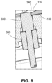
Fig. 8 is a side plan view of a blocking pin for use with the nozzle segment separation tool ofFig. 3 . -
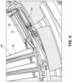
Fig. 9 is a perspective view of the nozzle segment separation tool being positioned about a segment of nozzles. -
Fig. 10 is a partial plan view of the nozzle catch plate of the nozzle segment separation tool in use. -
Fig. 11 is a further partial plan view of the nozzle catch plate of the nozzle segment separation tool and the blocking pin in use. -
Fig. 12 is a perspective view of the nozzle segment separation tool in position about a segment of nozzles. - Referring now to the drawings, in which like numerals refer to like elements throughout the several views,
Fig. 1 shows a schematic diagram of agas turbine engine 10 as may be used herein. Thegas turbine engine 10 may include acompressor 15. Thecompressor 15 compresses an incoming flow ofair 20. Thecompressor 15 delivers the compressed flow ofair 20 to a number ofcombustor cans 25. The combustor cans 25 mix the compressed flow ofair 20 with a pressurized flow offuel 30 and ignite the mixture to create a flow ofhot combustion gases 35. Although only a single combustor can 25 is shown, thegas turbine engine 10 may include any number ofcombustor cans 25 positioned in a circumferential array and the like. Alternatively, thecombustor 25 may be an annular combustor. The flow ofcombustion gases 35 is in turn delivered to aturbine 40. The flow ofcombustion gases 35 drives theturbine 40 to produce mechanical work. The mechanical work produced in theturbine 40 drives thecompressor 15 and anexternal load 50 such as an electrical generator and the like via arotor shaft 45. - The
gas turbine engine 10 may use natural gas, various types of syngas, liquid fuels, and/or other types of fuels and blends thereof. Thegas turbine engine 10 may be any one of a number of different gas turbine engines offered by General Electric Company of Schenectady, New York, including, but not limited to, those such as a 7-series or a 9-series heavy duty gas turbine engine and the like. Thegas turbine engine 10 may be part of a simple cycle or a combined cycle power generation system or other types of generation systems. Thegas turbine engine 10 may have different configurations and may use other types of components. Other types of gas turbine engines also may be used herein. Multiple gas turbine engines, other types of turbines, and other types of power generation equipment also may be used herein together. -
Fig. 2 is a partial sectional view of theturbine 40. Theturbine 40 includes a number ofstages 52. Generally described, eachstage 52 includes astationary row 54 ofnozzles 56 and a rotatingrow 58 ofturbine blades 60. In this example, threestages 52 are shown, a first stage, a second stage, and a third stage. Theturbine blades 60 in eachrow 58 are spaced circumferentially about, and extend radially outward from, arotor disk 62. Eachrotor disk 62 is coupled to therotor shaft 45. Aturbine casing 64 extends circumferentially about thenozzles 56. Thenozzles 56 are each coupled to theturbine casing 64 and eachnozzle 56 extends radially inward from theturbine casing 64 towards therotor shaft 45. Specifically, as will be described in more detail below, thenozzles 56 may be arranged in a number of segments 66 and may be attached to theturbine casing 64 via a number of shroud grooves 68 in a number ofshrouds 70. A hotcombustion gas path 72 may be defined between theturbine casing 64 and eachrotor disk 62. -
Fig. 3 shows an example of a nozzlesegment separation tool 100 as may be described herein. The nozzlesegment separation tool 100 may include a pair ofsupport plates 110. Thesupport plates 110 may be made out of any substantially rigid material such as stainless steel and the like. Positioned within thesupport plates 110 may be ahydraulic cylinder 120, a pushingbar 130, anozzle catch plate 140, and connecting elements as will be described in more detail below. - The
hydraulic cylinder 120 may be of conventional design. Specifically, thehydraulic cylinder 120 may include a hydraulicfluid port 150 and aninternal piston 160. Thehydraulic cylinder 120 may provide a single stroke or a double stroke. An exemplary hydraulic cylinder may be a five-ton capacity hydraulic cylinder sold by ENERPAC of Milwaukie, Wisconsin. Other type of hydraulic cylinders, other types of capacities, and other types of push or pull mechanisms may be used herein. - The pushing
bar 130 may extend within thesupport plates 110 from thehydraulic cylinder 120 to beneath thenozzle catch plate 140. The pushingbar 130 may have an elongated shape and may be positioned at an angle within thesupport plates 110. The pushingbar 130 may be made out of any type of substantially rigid material such as stainless steel and the like. As is shown inFig. 4 , the pushingbar 130 may be joined to thehydraulic cylinder 120 via a threadedadapter 170 attached to thepiston 160 and an L-shapedbar 180 bolted to the pushingbar 130. Specifically, the threadedadapter 170 and the L-shapedbar 180 may be joined via afirst bolt 190. The pushingbar 130 and the L-shapedbar 180 also may be joined by a pair ofsecond bolts 200. The pushingbar 130 and the L-shapedbar 180 also may be formed as a single element. Other types of connection means may be used. Aspacer 210 and the like also may be used between the pushingbar 130 and the L-shapedbar 180. Other components and other configurations may be used herein. - The
nozzle catch plate 140 may be positioned at the other end of thesupport plates 110. As is shown inFigs. 5 and 6 , thenozzle catch plate 140 may have a pair ofsupport arms 220 and a pair ofcatch arms 230. Thesupport arms 220 and thecatch arms 230 together form an L-shapedcatch surface 240. The bottom of thecatch arms 230 may have anangled surface 250 angling upwards toward the pushingbar 130. Thenozzle catch plate 140 may be joined to thesupport plates 110 via a pair ofpins 260 positioned within slots 270 in thesupport arms 220. Each slot 270 may have aspring 280 positioned therein in contact with thepin 260. Thesprings 280 serve to push thenozzle catch plate 140 downward within thesupport plates 110. Aspring plunger 290 also may be used to limit the relative movement of thenozzle catch plate 140. Removing thespring plunger 290 also allows the replacement of thenozzle catch plate 140 for use with different stages with different configurations. Other components and other configurations also may be used herein. - Positioned on the other end of the
support plates 110 adjacent to thehydraulic cylinder 120 may be ashroud plate 300. As is shown inFig. 7 , theshroud plate 300 may have a pair of shroud pins 310 on either side thereof. The shroud pins 310 are sized and positioned to be inserted within the shroud grooves 68 within the turbine shrouds 70. Theshroud plate 300 and the shroud pins 310 serve to stabilize the nozzlesegment separation tool 100 when adjacent to the segments 66 of thenozzles 56. Referring again toFig. 3 , apositioning pipe 320 may be welded to thesupport plates 110. Thepositioning pipe 320 may be used to position and move the nozzlesegment separation tool 100 with respect to the segments 66 of thenozzles 56. Other components and other configurations may be used herein. - The nozzle
segment separation tool 100 may be used with a blockingpin 330. As is shown inFig. 8 , the blockingpin 330 may have aflat surface 340 sized to accommodate the pushingbar 130. The blockingpin 330 may be positioned with theturbine casing 64 via a blockingnut 350. Blocking pins 330 of differing sizes and shapes may be used with different stages. Other components and other configurations may be used herein. - In use as is shown in
Figs. 9-12 , the nozzlesegment separation tool 100 may be inserted within the shroud grooves 68 of theturbine shroud 70 via theshroud plate 300 and shroud pins 310. Likewise, the blockingpin 330 may be inserted within theturbine casing 64 and locked into place with the lockingnut 350. As the nozzlesegment separation tool 100 is positioned underneath or about thenozzles 56, theangled surface 250 of thenozzle catch plate 140 rides along the blockingpin 330 until thecatch surface 240 moves beyond thenozzle 56. The nozzlesegment separation tool 100 continues to advance until the pushingbar 130 contacts theflat surface 340 of the blockingpin 330. - The nozzle
segment separation tool 100 thus may be positioned with thecatch surface 240 of thenozzle catch plate 140 in contact with thenozzle 56 and the pushingbar 130 in contact with theflat surface 340 of the blockingpin 330. Once the pushingbar 130 is blocked, thehydraulic cylinder 120 may be activated to pull thesupport plates 110 and thenozzle catch plate 140 in the direction of arrow 360. This pulling action forces thenozzles 56 and/or the nozzle segments 66 to separate. Once separated, thenozzles 56 may be removed in the ordinary fashion. - It should be apparent that the foregoing relates only to certain embodiments of this application and resultant patent. Numerous changes and modifications may be made herein by one of ordinary skill in the art without departing from the general spirit and scope of the invention as defined by the following claims and the equivalents thereof.
- Further aspects of the invention are provided by the subject matter of the following clauses:
- 1. A nozzle segment separation tool for use with a pair of adjacent nozzle segments in a casing of a turbine, comprising: a pair of support plates; a hydraulic cylinder positioned within the pair of support plates; a pushing bar attached to the hydraulic cylinder; a nozzle catch plate positioned within the pair of support plates; and a blocking pin inserted through the casing; wherein the blocking pin forces the nozzle catch plate to engage a first nozzle segment of the pair of adjacent nozzle segments and blocks movement of the pushing bar such that the nozzle catch plates separates the pair of adjacent nozzle segments.
- 2. The nozzle segment separation tool of any preceding clause, wherein the pair of support plates comprises stainless steel.
- 3. The nozzle segment separation tool of any preceding clause, wherein the pushing bar comprises stainless steel.
- 4. The nozzle segment separation tool of any preceding clause, wherein the hydraulic cylinder and the pushing bar are connected via a threaded adapter.
- 5. The nozzle segment separation tool of any preceding clause, wherein the hydraulic cylinder and the pushing bar are connected via an L-shaped bar.
- 6. The nozzle segment separation tool of any preceding clause, wherein the nozzle catch plate comprises a pair of catch arms and a pair of support arms.
- 7. The nozzle segment separation tool of any preceding clause, wherein the pair of catch arms and the pair of support arms comprise a catch surface for the first nozzle segment.
- 8. The nozzle segment separation tool of any preceding clause, wherein the pair of catch arms comprises an angled surface for the pushing bar.
- 9. The nozzle segment separation tool of any preceding clause, wherein each of the pair of support arms comprises a slot with a spring-loaded pin therein.
- 10. The nozzle segment separation tool of any preceding clause, wherein the nozzle catch plate comprises a spring plunger therein.
- 11. The nozzle segment separation tool of any preceding clause, further comprising a shroud plate positioned adjacent to the pair of support plates.
- 12. The nozzle segment separation tool of any preceding clause, wherein the shroud plate comprises a plurality of shroud pins.
- 13. The nozzle segment separation tool of any preceding clause, wherein the blocking pin comprise a flat face for the pushing bar.
- 14. The nozzle segment separation tool of any preceding clause, wherein the blocking pin comprises a blocking nut.
- 15. A method of separating a pair of adjacent nozzles in a casing of a turbine, comprising: sliding a nozzle segment separation tool about the pair of adjacent nozzles; inserting a blocking pin through the casing; forcing a nozzle catch plate of the nozzle segment separation tool into contact with one of the pair of adjacent nozzles by the blocking pin; engaging the blocking pin with a pushing bar of the nozzle segment separation tool; and pulling the one of the pair of adjacent nozzles by the nozzle catch plate.
- 16. A nozzle segment separation tool for use with a pair of adjacent nozzle segments in a casing of a turbine, comprising: a pair of support plates; a hydraulic cylinder positioned within the pair of support plates; a pushing bar attached to the hydraulic cylinder; a spring-loaded nozzle catch plate positioned within the pair of support plates; and a blocking pin inserted through the casing; wherein the blocking pin forces the spring-loaded nozzle catch plate to engage a first nozzle segment of the pair of adjacent nozzle segments and blocks movement of the pushing bar such that the spring-loaded nozzle catch plate separates the pair of adjacent nozzle segments via the hydraulic cylinder.
- 17. The nozzle segment separation tool of any preceding clause, wherein the pair of support plates and the pushing bar comprise stainless steel.
- 18. The nozzle segment separation tool of claim 16, wherein the spring-loaded nozzle catch plate comprises a pair of catch arms and a pair of support arms.
- 19. The nozzle segment separation tool of any preceding clause, wherein the pair of catch arms and the pair of support arms comprises a catch surface for the nozzle.
- 20. The nozzle segment separation tool of any preceding clause, wherein the blocking pin comprise a flat face for the pushing bar.
Claims (15)
- A nozzle segment separation tool (100) for use with a pair of adjacent nozzle segments (66) in a casing (64) of a turbine (40), comprising:a pair of support plates (110);a hydraulic cylinder (120) positioned within the pair of support plates (110);a pushing bar (130) attached to the hydraulic cylinder (120);a nozzle catch plate (140) positioned within the pair of support plates (110); anda blocking pin (330) inserted through the casing (64);wherein the blocking pin (330) forces the nozzle catch plate (140) to engage the a first nozzle segment (66) of the pair of adjacent nozzle segments (66) and blocks movement of the pushing bar (130) such that the nozzle catch plate (140) separates the pair of adjacent nozzle segments (66).
- The nozzle segment separation tool (100) of claim 1, wherein the pair of support plates (110) comprises stainless steel.
- The nozzle segment separation tool (100) of claim 1, wherein the pushing bar (130) comprises stainless steel.
- The nozzle segment separation tool (100) of claim 1, wherein the hydraulic cylinder (120) and the pushing bar (130) are connected via a threaded adapter (170).
- The nozzle segment separation tool (100) of claim 1, wherein the hydraulic cylinder (120) and the pushing bar (130) are connected via an L-shaped bar (180).
- The nozzle segment separation tool (100) of claim 1, wherein the nozzle catch plate (140) comprises a pair of catch arms (230) and a pair of support arms (220).
- The nozzle segment separation tool (100) of claim 6, wherein the pair of catch arms (230) and the pair of support arms (220) comprise a catch surface (240) for the first nozzle segment (66).
- The nozzle segment separation tool (100) of claim 6, wherein the pair of catch arms (230) comprises an angled surface (250) for the pushing bar (130).
- The nozzle segment separation tool (100) of claim 6, wherein each of the pair of support arms (220) comprises a slot (270) with a spring-loaded pin (260) therein.
- The nozzle segment separation tool (100) of claim 1, wherein the nozzle catch plate (140) comprises a spring plunger (290) therein.
- The nozzle segment separation tool (100) of claim 1, further comprising a shroud plate (300) positioned adjacent to the pair of support plates (110).
- The nozzle segment separation tool (100) of claim 11, wherein the shroud plate (300) comprises a plurality of shroud pins (310).
- The nozzle segment separation tool (100) of claim 1, wherein the blocking pin (330) comprise a flat face (340) for the pushing bar (130).
- The nozzle segment separation tool (100) of claim 1, wherein the blocking pin (330) comprises a blocking nut (350).
- A method of separating a pair of adjacent nozzles (56) in a casing (64) of a turbine (40), comprising:sliding a nozzle segment separation tool (100) about the pair of adjacent nozzles (56);inserting a blocking pin (330) through the casing (64);forcing a nozzle catch plate (140) of the nozzle segment separation tool (100) into contact with one of the pair of adjacent nozzles (56) by the blocking pin (330);engaging the blocking pin (330) with a pushing bar (130) of the nozzle segment separation tool (100); andpulling the one of the pair of adjacent nozzles (56) by the nozzle catch plate (140).
Applications Claiming Priority (1)
| Application Number | Priority Date | Filing Date | Title |
|---|---|---|---|
| PL44548523 | 2023-07-05 |
Publications (1)
| Publication Number | Publication Date |
|---|---|
| EP4491848A1 true EP4491848A1 (en) | 2025-01-15 |
Family
ID=91481960
Family Applications (1)
| Application Number | Title | Priority Date | Filing Date |
|---|---|---|---|
| EP24181517.4A Pending EP4491848A1 (en) | 2023-07-05 | 2024-06-11 | Separation tool and method for nozzle segments of gas turbines |
Country Status (5)
| Country | Link |
|---|---|
| US (1) | US20260061531A1 (en) |
| EP (1) | EP4491848A1 (en) |
| JP (1) | JP2025013745A (en) |
| KR (1) | KR20250007423A (en) |
| CN (1) | CN119260654A (en) |
Citations (4)
| Publication number | Priority date | Publication date | Assignee | Title |
|---|---|---|---|---|
| US3673668A (en) * | 1970-08-31 | 1972-07-04 | Ind Solvers Inc | Vane ejector tool |
| GB1553872A (en) * | 1975-09-02 | 1979-10-10 | Gen Electric | Method and apparatus for removing turbomachinery stator vanes |
| US20160160689A1 (en) * | 2013-12-05 | 2016-06-09 | General Electric Company | Turbine shroud block removal apparatus |
| EP3225779A1 (en) * | 2016-03-28 | 2017-10-04 | General Electric Company | Removal tool |
Family Cites Families (8)
| Publication number | Priority date | Publication date | Assignee | Title |
|---|---|---|---|---|
| US20080010800A1 (en) * | 2001-12-20 | 2008-01-17 | West Central Ohio Tool Distributors, Ltd. | Automotive Wheel Assembly Removal Tool Actuators |
| US7337648B2 (en) * | 2003-08-28 | 2008-03-04 | Timberwolf Corporation | Clamp and repair tool |
| DE502004011310D1 (en) * | 2004-07-09 | 2010-08-05 | Siemens Ag | Device for removing blades of a turbine or a compressor |
| DE202005003450U1 (en) * | 2005-03-04 | 2005-05-19 | Klann-Spezial-Werkzeugbau-Gmbh | Device for removing and pressing in a wheel bearing at the rear |
| US8381379B2 (en) * | 2009-04-17 | 2013-02-26 | General Electric Company | Apparatus and tools for use with compressors |
| US9494040B2 (en) * | 2014-02-06 | 2016-11-15 | Siemens Energy, Inc. | Turbine engine blade removal apparatus and method |
| US9381602B2 (en) * | 2014-05-14 | 2016-07-05 | General Electric Company | Turbomachine bucket displacement apparatus and method of use |
| US20170015538A1 (en) * | 2015-07-15 | 2017-01-19 | Hb Venture Group Llc | Lock Pin Releasing Device for Truck Trailer Axles |
-
2024
- 2024-05-30 CN CN202410690499.7A patent/CN119260654A/en active Pending
- 2024-05-31 JP JP2024089441A patent/JP2025013745A/en active Pending
- 2024-06-11 EP EP24181517.4A patent/EP4491848A1/en active Pending
- 2024-06-27 KR KR1020240084887A patent/KR20250007423A/en active Pending
- 2024-06-28 US US18/758,765 patent/US20260061531A1/en active Pending
Patent Citations (4)
| Publication number | Priority date | Publication date | Assignee | Title |
|---|---|---|---|---|
| US3673668A (en) * | 1970-08-31 | 1972-07-04 | Ind Solvers Inc | Vane ejector tool |
| GB1553872A (en) * | 1975-09-02 | 1979-10-10 | Gen Electric | Method and apparatus for removing turbomachinery stator vanes |
| US20160160689A1 (en) * | 2013-12-05 | 2016-06-09 | General Electric Company | Turbine shroud block removal apparatus |
| EP3225779A1 (en) * | 2016-03-28 | 2017-10-04 | General Electric Company | Removal tool |
Also Published As
| Publication number | Publication date |
|---|---|
| US20260061531A1 (en) | 2026-03-05 |
| CN119260654A (en) | 2025-01-07 |
| KR20250007423A (en) | 2025-01-14 |
| JP2025013745A (en) | 2025-01-28 |
Similar Documents
| Publication | Publication Date | Title |
|---|---|---|
| US6968702B2 (en) | Nozzle bolting arrangement for a turbine | |
| JP6938610B2 (en) | Clearance control ring assembly | |
| US8677591B2 (en) | Methods and system for disassembling a machine | |
| CN203809129U (en) | Gas turbine engine and assemblies thereof | |
| CN105765168B (en) | Radial Tie Bolt Support Spring | |
| KR20200020415A (en) | Turbine, gas turbine including the same, assembling method of turbine, and disassembling method of turbine | |
| WO2013188731A1 (en) | Rotor assembly, corresponding gas turbine engine and method of assembling | |
| EP3391998A1 (en) | Turbomachine coupling assembly | |
| EP4036374B1 (en) | Rotary machine with a rotor disk and blades | |
| US12281591B2 (en) | T-fairing installation tooling assembly | |
| EP3388634B1 (en) | Gas turbine blade assembly having retainer assembling structure, and gas turbine having same | |
| KR102120116B1 (en) | Turbine blade of gas turbine having cast tip | |
| US20260061531A1 (en) | Separation tool and method for nozzle segments of gas turbines | |
| EP2354458A2 (en) | Locking spacer assembly | |
| EP3077630A1 (en) | Turbine shroud block removal apparatus | |
| EP2562359A2 (en) | Turbine nozzle vane retention system | |
| EP4644671A1 (en) | Separation tool and method for nozzle segments of gas turbines | |
| EP4534909A1 (en) | Aft inner cap plate removal method and tooling for a combustor with micromixer tubes | |
| BR102024013368A2 (en) | TOOL AND SEPARATION METHOD FOR GAS TURBINE NOZZLE SEGMENTS | |
| JP7159498B1 (en) | Method for assembling stator vane in gas turbine casing | |
| KR102120097B1 (en) | Stationary vane nozzle of gas turbine | |
| EP4538596A1 (en) | Aft inner cap plate removal method and tooling for a combustor with micromixer tubes | |
| EP4198266A1 (en) | Blade tip shroud for gas turbine | |
| US20240157424A1 (en) | Systems and methods for deformation correction of a gas turbine shroud |
Legal Events
| Date | Code | Title | Description |
|---|---|---|---|
| PUAI | Public reference made under article 153(3) epc to a published international application that has entered the european phase |
Free format text: ORIGINAL CODE: 0009012 |
|
| STAA | Information on the status of an ep patent application or granted ep patent |
Free format text: STATUS: THE APPLICATION HAS BEEN PUBLISHED |
|
| AK | Designated contracting states |
Kind code of ref document: A1 Designated state(s): AL AT BE BG CH CY CZ DE DK EE ES FI FR GB GR HR HU IE IS IT LI LT LU LV MC ME MK MT NL NO PL PT RO RS SE SI SK SM TR |
|
| STAA | Information on the status of an ep patent application or granted ep patent |
Free format text: STATUS: REQUEST FOR EXAMINATION WAS MADE |
|
| 17P | Request for examination filed |
Effective date: 20250628 |
|
| RAP3 | Party data changed (applicant data changed or rights of an application transferred) |
Owner name: GE VERNOVA TECHNOLOGY GMBH |