EP4491827A1 - Mounting system for exterior and interior cladding systems - Google Patents
Mounting system for exterior and interior cladding systems Download PDFInfo
- Publication number
- EP4491827A1 EP4491827A1 EP23184613.0A EP23184613A EP4491827A1 EP 4491827 A1 EP4491827 A1 EP 4491827A1 EP 23184613 A EP23184613 A EP 23184613A EP 4491827 A1 EP4491827 A1 EP 4491827A1
- Authority
- EP
- European Patent Office
- Prior art keywords
- mounting system
- straight
- attached
- mounting
- panel
- Prior art date
- Legal status (The legal status is an assumption and is not a legal conclusion. Google has not performed a legal analysis and makes no representation as to the accuracy of the status listed.)
- Pending
Links
Images




Classifications
-
- E—FIXED CONSTRUCTIONS
- E04—BUILDING
- E04F—FINISHING WORK ON BUILDINGS, e.g. STAIRS, FLOORS
- E04F13/00—Coverings or linings, e.g. for walls or ceilings
- E04F13/07—Coverings or linings, e.g. for walls or ceilings composed of covering or lining elements; Sub-structures therefor; Fastening means therefor
- E04F13/072—Coverings or linings, e.g. for walls or ceilings composed of covering or lining elements; Sub-structures therefor; Fastening means therefor composed of specially adapted, structured or shaped covering or lining elements
- E04F13/073—Coverings or linings, e.g. for walls or ceilings composed of covering or lining elements; Sub-structures therefor; Fastening means therefor composed of specially adapted, structured or shaped covering or lining elements for particular building parts, e.g. corners or columns
- E04F13/0733—Coverings or linings, e.g. for walls or ceilings composed of covering or lining elements; Sub-structures therefor; Fastening means therefor composed of specially adapted, structured or shaped covering or lining elements for particular building parts, e.g. corners or columns for corners
-
- E—FIXED CONSTRUCTIONS
- E04—BUILDING
- E04F—FINISHING WORK ON BUILDINGS, e.g. STAIRS, FLOORS
- E04F13/00—Coverings or linings, e.g. for walls or ceilings
- E04F13/07—Coverings or linings, e.g. for walls or ceilings composed of covering or lining elements; Sub-structures therefor; Fastening means therefor
- E04F13/08—Coverings or linings, e.g. for walls or ceilings composed of covering or lining elements; Sub-structures therefor; Fastening means therefor composed of a plurality of similar covering or lining elements
- E04F13/0801—Separate fastening elements
- E04F13/0803—Separate fastening elements with load-supporting elongated furring elements between wall and covering elements
- E04F13/081—Separate fastening elements with load-supporting elongated furring elements between wall and covering elements with additional fastening elements between furring elements and covering elements
- E04F13/083—Hooking means on the back side of the covering elements
-
- E—FIXED CONSTRUCTIONS
- E04—BUILDING
- E04F—FINISHING WORK ON BUILDINGS, e.g. STAIRS, FLOORS
- E04F13/00—Coverings or linings, e.g. for walls or ceilings
- E04F13/07—Coverings or linings, e.g. for walls or ceilings composed of covering or lining elements; Sub-structures therefor; Fastening means therefor
- E04F13/08—Coverings or linings, e.g. for walls or ceilings composed of covering or lining elements; Sub-structures therefor; Fastening means therefor composed of a plurality of similar covering or lining elements
- E04F13/0801—Separate fastening elements
- E04F13/0832—Separate fastening elements without load-supporting elongated furring elements between wall and covering elements
- E04F13/0833—Separate fastening elements without load-supporting elongated furring elements between wall and covering elements not adjustable
- E04F13/0851—Hooking means on the back side of the covering elements
-
- E—FIXED CONSTRUCTIONS
- E04—BUILDING
- E04F—FINISHING WORK ON BUILDINGS, e.g. STAIRS, FLOORS
- E04F13/00—Coverings or linings, e.g. for walls or ceilings
- E04F13/07—Coverings or linings, e.g. for walls or ceilings composed of covering or lining elements; Sub-structures therefor; Fastening means therefor
- E04F13/08—Coverings or linings, e.g. for walls or ceilings composed of covering or lining elements; Sub-structures therefor; Fastening means therefor composed of a plurality of similar covering or lining elements
- E04F13/12—Coverings or linings, e.g. for walls or ceilings composed of covering or lining elements; Sub-structures therefor; Fastening means therefor composed of a plurality of similar covering or lining elements of metal or with an outer layer of metal or enameled metal
Definitions
- the present invention relates to a mounting system for exterior and interior cladding systems, specifically for interior cladding systems, which allows for a reduced gap between the mounted panels, and a reduced wall-to-panel-distance, which mounting system can universally be used for the "start" panel, the "middle” panel(s) and the “end” panel, and preferably also angled mounting arrangements.
- Typical façade cladding systems in the past were made from hot pressed resin/fiber laminates (HPL material) which were relatively thick, and thus heavy. For this reason, they were predominately used for exterior and not interior applications.
- new types of facade cladding systems were developed, which are based on lightweight aluminum cover sheets and a non-combustible mineral or mineral polymer core. Compared to HPL panels the aluminum-based panels are considerably thinner and light weighed, so that they can also be used for interior applications.
- typical mounting systems for cladding panels have been developed for exterior cladding systems these mounting systems are less suited for interior applications because the gap between the mounted panels is between about 10 to 20 mm, which is unattractive for interior applications.
- a "U-shaped profile” is the three-dimensional extension in z-direction of the two-dimensional (x-y-direction) shape of the letter "U” in a Cartesian coordinate system (see Fig. 1 ).
- a Cartesian coordinate system for a three-dimensional space consists of an ordered triplet of lines (the axes) x, y and z that go through a common point (the origin), and are pair-wise perpendicular.
- the two-dimensional (x-y-direction) shape of the letter “U” consists of a straight base (B), having a length “l B “ and a thickness "t B ", wherein the base has a straight leg attached at each end of the base (L1 and L2), having a length "l L1 " and “l L2 " and a thickness "t L1 " and “t L2 ".
- Each of the (inner) angles ⁇ 1 and ⁇ 2 between the base and L1 and/or L2 is - independent from one another - 90° ⁇ 10°, preferably ⁇ 5°, more preferred ⁇ 2° and most preferred ⁇ 0°.
- U-opening is the open side of the U-shaped profile, which is located opposite of the base (B).
- the three-dimensional extension in z-direction i.e. the profile depth in the mounting systems (1) according to the present invention is typically between 10 mm and 200 mm, preferably between 15 mm and 150 mm, more preferred between 20 mm and 100 mm.
- the thickness t B , t L1 and t L2 is - independent from one another - between 0.5 mm and 5.0 mm, preferably between 0.8 mm and 3.0 mm, more preferred between 1.0 mm and 2.0 mm.
- the thicknesses of t B , t L1 and t L2 are about identical.
- the length of the straight base (B) "l B " depends on the thickness of the cladding system and is typically in the range of from 2 mm to 20 mm, preferably from 3 mm to 15 mm and more preferred from 3 mm to 6 mm.
- the length of the straight legs L1 and L2 "l L1 " and “l L2 " are - independently from one another in the range of from 5 mm to 50 mm, preferably from 7 mm to 25 mm and more preferred from 8 mm to 15 mm.
- the straight link which joins the two back to back combined U's U1 and U2 with U3 determines the gap between the panels (2) and is typically 10 mm to 60 mm, preferably from 15 mm to 40 mm and more preferred from 18 mm to 22 mm long.
- the topography of the surface of the straight legs may be even, i.e. not showing any elevations, or it may exhibit a wave-like structure or several elevations with peak to valley distances from 0.1 mm to 0.5 mm, preferably from 0,2-0,4 mm, more preferred from 0,2-0,3 mm.
- the mounting system (1) may further exhibit guiding rails for Fixation means such as a rivet (3) or nail eventually in combination with a washer (4).
- the material of the mounting system (1) is not critical and can be a plastic material like polypropylene, polyamide or a metal such as aluminum, iron or the like.
- the mounting system (1) can be manufactured by known methods e.g. by mold casting, 3D printing or sinter technology to name just a few.
- Figure 3 shows an exemplary mounting system (1) of the present invention (with two panels (2) mounted).
- the conventional way to install a panel (2) with known mounting systems is easy, but require an about 15 mm space to slide the edge of each panel (2) inside.
- the solution according to the present invention is different: slots on the back of the panel (2) allow for an installation from top to bottom. As a result, there is almost no visible gap (see Fig. 5 right); literally, the gap can be reduced to 0 mm.
- the mounting system (1a) according to the present invention can easily be adapted by cutting the profile accordingly (see Fig. 4 ).
- the system can also be used for angled wall cladding (see Fig. 8 ).
Landscapes
- Engineering & Computer Science (AREA)
- Architecture (AREA)
- Civil Engineering (AREA)
- Structural Engineering (AREA)
- Finishing Walls (AREA)
Abstract
The present invention relates to a mounting system for exterior and interior cladding systems, specifically for interior cladding systems, which allows for a reduced gap between the mounted panels, and a reduced wall-to-panel-distance, which mounting system can universally be used for the "start" panel, the "middle" panel(s) and the "end" panel, and preferably also angled mounting problems.
Description
- The present invention relates to a mounting system for exterior and interior cladding systems, specifically for interior cladding systems, which allows for a reduced gap between the mounted panels, and a reduced wall-to-panel-distance, which mounting system can universally be used for the "start" panel, the "middle" panel(s) and the "end" panel, and preferably also angled mounting arrangements.
- Typical façade cladding systems in the past were made from hot pressed resin/fiber laminates (HPL material) which were relatively thick, and thus heavy. For this reason, they were predominately used for exterior and not interior applications. In recent years new types of facade cladding systems were developed, which are based on lightweight aluminum cover sheets and a non-combustible mineral or mineral polymer core. Compared to HPL panels the aluminum-based panels are considerably thinner and light weighed, so that they can also be used for interior applications. Yet, since typical mounting systems for cladding panels have been developed for exterior cladding systems these mounting systems are less suited for interior applications because the gap between the mounted panels is between about 10 to 20 mm, which is unattractive for interior applications. Moreover, the wall-to-panel-distance with these known "exterior mounting systems" is very high (> 30 mm) so that the interior living space is excessively reduced which is economically unattractive. Another disadvantage with known mounting systems is that three different mounting systems must be provided for the "start" panel, the "middle" panel(s) and the "end" panel; even more and - beyond that - other systems are needed when the panels are mounted on angled walls.
- It was, therefore, an object of the present invention to provide a mounting system
- which can be used for exterior (withstanding high wind resistance) as well as interior (exhibiting thin system thickness) cladding systems, specifically for interior cladding systems
- which allows for a reduced gap between the mounted panels, preferably with a gap distance of <10 mm, more preferred ≤ 8 mm and most preferred ≤ 6 mm; especially for interior applications the gap preferably has a distance of ≤ 5 mm, more preferred of ≤ 3 mm and most preferred between 1 and 2 mm;
- with a wall-to-panel-distance of ≤ 30 mm, preferably ≤ 25 mm and more preferred ≤ 20 mm;
- which can universally be used for the "start" panel, the "middle" panel(s) and the "end" panel, and preferably angled mounting problems (one system for all mounting tasks).
- The above problems are solved with a mounting system which is a combination of joined U-shaped profiles, comprising
- 2 U-shaped profiles U1 and U2 each consisting of a straight base B and two straight legs L1 and L2, wherein the two U-shaped profiles are attached to each other by the joint straight base B and
- a straight link attached to one straight leg L1 or L2 of U2, and
- a further U-shaped profile U3 attached to the end of the straight link, which is not attached to L1 or L2 of U2, such that the two U-shaped profiles U2 and U3 are facing each other with their U-openings like mirror images, and
- at least one of
- a) a further U-shaped profile U4 attached to U3 by the joint straight base with U3, so that the U-openings of U3 and U4 point in 180° opposite directions; (see
Fig. 2b ); - b) a further U-shaped profile U4 attached to the straight base B of U3 via one of U4's straight legs L1 or L2 so that the U-openings of U3 and U4 point in directions, which form an angle of 90° (see
Fig. 2a ).
- a) a further U-shaped profile U4 attached to U3 by the joint straight base with U3, so that the U-openings of U3 and U4 point in 180° opposite directions; (see
-
- Figure 1
- shows a U-shaped profile.
- Figure 2a
- shows mounting system according to the present invention, wherein a Ushaped profile U4 is attached to the straight base B of U3 via one of U4's straight legs L1 or L2 so that the U-openings of U3 and U4 point in directions, which form an angle of 90°.
- Figure 2b
- shows a mounting system according to the present invention wherein a U-shaped profile U4 is attached to U3 by the joint straight base with U3, so that the U-openings of U3 and U4 point in 180° opposite directions.
- Figure 3
- shows an exemplary mounting system of the present invention with two panels (2) mounted.
- Figure 4
- shows several mounting systems (1) according to the present invention, which can be individually adapted by cutting the system, preferably along predefined lines.
- Figure 5
- left shows a mounting system (1) according to the present invention with a gap (albeit a much smaller gap than in conventional mounting systems), whereas
figure 5 right shows two cut mounting systems (1) according to the present invention with almost no visible gap. - Figure 6
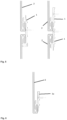
- shows the mounting of a "start" panel (2).
- Figure 7
- shows the mounting of an "end" panel (2).
- Figure 8
- shows an angled wall cladding.
- Figure 9
- shows a rivet (3) and washer (4) mounting.
- According to the present invention a "U-shaped profile" is the three-dimensional extension in z-direction of the two-dimensional (x-y-direction) shape of the letter "U" in a Cartesian coordinate system (see
Fig. 1 ). A Cartesian coordinate system for a three-dimensional space consists of an ordered triplet of lines (the axes) x, y and z that go through a common point (the origin), and are pair-wise perpendicular. The two-dimensional (x-y-direction) shape of the letter "U" consists of a straight base (B), having a length "lB" and a thickness "tB", wherein the base has a straight leg attached at each end of the base (L1 and L2), having a length "lL1" and "lL2" and a thickness "tL1" and "tL2". Each of the (inner) angles α1 and α2 between the base and L1 and/or L2 is - independent from one another - 90°±10°, preferably ±5°, more preferred ±2° and most preferred ±0°. - "U-opening" is the open side of the U-shaped profile, which is located opposite of the base (B).
- The three-dimensional extension in z-direction, i.e. the profile depth in the mounting systems (1) according to the present invention is typically between 10 mm and 200 mm, preferably between 15 mm and 150 mm, more preferred between 20 mm and 100 mm.
- The thickness tB, tL1 and tL2 is - independent from one another - between 0.5 mm and 5.0 mm, preferably between 0.8 mm and 3.0 mm, more preferred between 1.0 mm and 2.0 mm. Preferably, the thicknesses of tB, tL1 and tL2 are about identical.
- The length of the straight base (B) "lB" depends on the thickness of the cladding system and is typically in the range of from 2 mm to 20 mm, preferably from 3 mm to 15 mm and more preferred from 3 mm to 6 mm.
- The length of the straight legs L1 and L2 "lL1" and "lL2" are - independently from one another in the range of from 5 mm to 50 mm, preferably from 7 mm to 25 mm and more preferred from 8 mm to 15 mm.
- The straight link, which joins the two back to back combined U's U1 and U2 with U3 determines the gap between the panels (2) and is typically 10 mm to 60 mm, preferably from 15 mm to 40 mm and more preferred from 18 mm to 22 mm long.
- The topography of the surface of the straight legs may be even, i.e. not showing any elevations, or it may exhibit a wave-like structure or several elevations with peak to valley distances from 0.1 mm to 0.5 mm, preferably from 0,2-0,4 mm, more preferred from 0,2-0,3 mm.
- The mounting system (1) may further exhibit guiding rails for Fixation means such as a rivet (3) or nail eventually in combination with a washer (4).
- The material of the mounting system (1) is not critical and can be a plastic material like polypropylene, polyamide or a metal such as aluminum, iron or the like.
- The mounting system (1) can be manufactured by known methods e.g. by mold casting, 3D printing or sinter technology to name just a few.
-
Figure 3 shows an exemplary mounting system (1) of the present invention (with two panels (2) mounted).The conventional way to install a panel (2) with known mounting systems is easy, but require an about 15 mm space to slide the edge of each panel (2) inside. The solution according to the present invention is different: slots on the back of the panel (2) allow for an installation from top to bottom. As a result, there is almost no visible gap (seeFig. 5 right); literally, the gap can be reduced to 0 mm. - For a vertical layout, usually prior art systems use a small screw and a washer (4) to support the panel (2) at the bottom. However, this screw and washer (4) can only be assembled at a workshop on a bench with a vise. The present mounting system (1) can use a cheaper and easier solution using e.g. a black lacquered rivet (3); the assembly can be made at building site (see
Fig. 9 ). - For the "start" panel (2) (see
Fig. 6 ), the "middle" panel(s)(2) and the "end" panel (2) (seeFig. 7 ), the mounting system (1a) according to the present invention can easily be adapted by cutting the profile accordingly (seeFig. 4 ). - The system can also be used for angled wall cladding (see
Fig. 8 ).
Claims (16)
- Mounting system (1) for exterior and interior cladding systems, comprising a combination of joined U-shaped profiles, the combination comprising- 2 U-shaped profiles U1 and U2 each consisting of a straight base B and two straight legs L1 and L2, wherein the two U-shaped profiles are attached to each other by the joint straight base B and- a straight link attached to one straight leg L1 or L2 of U2, and- a further U-shaped profile U3 attached to the end of the straight link, which is not attached to L1 or L2 of U2, such that the two U-shaped profiles U2 and U3 are facing each other with their U-openings like mirror images, and- at least one ofa) a further U-shaped profile U4 attached to U3 by the joint straight base with U3, so that the U-openings of U3 and U4 point in 180° opposite directions;b) a further U-shaped profile U4 attached to the straight base B of U3 via one of U4's straight legs L1 or L2 so that the U-openings of U3 and U4 point in directions, which form an angle of 90°.
- Mounting system (1) according to claim 1 having a profile depth between 10 mm and 200 mm.
- Mounting system (1) according to claim 1 or 2, wherein the thickness tB, tL1 and tL2 is - independent from one another - between 0.5 mm and 5.0 mm.
- Mounting system (1) according to claim 3, wherein the thicknesses of ts, tu and tL2 are about identical.
- Mounting system (1) according to one of claims 1-4, wherein the length of the straight base (B) "lB" is in the range of from 2 mm to 20 mm.
- Mounting system (1) according to one of claims 1-5, wherein the length of the straight legs L1 and L2 "lL1" and "lL2" are - independently from one another - in the range of from 5 mm to 50 mm.
- Mounting system (1) according to one of claims 1-6, wherein the straight link, which joins the two back to back combined U's U1 and U2 with U3 is 10 mm to 60 mm long.
- Mounting system (1) according to one of claims 1-7, wherein the topography of the surface of the straight legs is even, or exhibits a wave-like structure or exhibits several elevations with peak to valley distances from 0.1 mm to 0.5 mm.
- Mounting system (1) according to one of claims 1-8, further exhibiting guiding rails for Fixation means.
- Mounting system (1) according to one of claims 1-9, wherein the material of the mounting system (1) is a plastic material or a metal.
- Method of manufacturing the mounting system (1) of claim 1 by mold casting, 3D printing or by using sinter technology.
- Use of a mounting system (1) according to one of claims 1 to 10 for exterior and preferably interior cladding systems.
- The use of claim 12 wherein the gap between mounted panels (2) is <10 mm, preferably ≤ 5 mm.
- The use of claim 12 or 13, wherein the wall-to-panel-distance is ≤ 30 mm.
- The use of claims 12, 13 or 14 for mounting start panels (2), middle panels (2) and end panel (2).
- The use of one of claims 12-15 for angled mounting problems.
Priority Applications (1)
| Application Number | Priority Date | Filing Date | Title |
|---|---|---|---|
| EP23184613.0A EP4491827A1 (en) | 2023-07-11 | 2023-07-11 | Mounting system for exterior and interior cladding systems |
Applications Claiming Priority (1)
| Application Number | Priority Date | Filing Date | Title |
|---|---|---|---|
| EP23184613.0A EP4491827A1 (en) | 2023-07-11 | 2023-07-11 | Mounting system for exterior and interior cladding systems |
Publications (1)
| Publication Number | Publication Date |
|---|---|
| EP4491827A1 true EP4491827A1 (en) | 2025-01-15 |
Family
ID=87245772
Family Applications (1)
| Application Number | Title | Priority Date | Filing Date |
|---|---|---|---|
| EP23184613.0A Pending EP4491827A1 (en) | 2023-07-11 | 2023-07-11 | Mounting system for exterior and interior cladding systems |
Country Status (1)
| Country | Link |
|---|---|
| EP (1) | EP4491827A1 (en) |
Citations (3)
| Publication number | Priority date | Publication date | Assignee | Title |
|---|---|---|---|---|
| EP0121120A2 (en) * | 1983-04-02 | 1984-10-10 | Eltreva AG | Façade covering with a sub-construction |
| WO2017083815A1 (en) * | 2015-11-15 | 2017-05-18 | M Franklin | Building panel leveling system |
| EP3540145A1 (en) * | 2018-03-16 | 2019-09-18 | 3A Composites GmbH | Cladding element and system for a wall |
-
2023
- 2023-07-11 EP EP23184613.0A patent/EP4491827A1/en active Pending
Patent Citations (3)
| Publication number | Priority date | Publication date | Assignee | Title |
|---|---|---|---|---|
| EP0121120A2 (en) * | 1983-04-02 | 1984-10-10 | Eltreva AG | Façade covering with a sub-construction |
| WO2017083815A1 (en) * | 2015-11-15 | 2017-05-18 | M Franklin | Building panel leveling system |
| EP3540145A1 (en) * | 2018-03-16 | 2019-09-18 | 3A Composites GmbH | Cladding element and system for a wall |
Similar Documents
| Publication | Publication Date | Title |
|---|---|---|
| CN102251618A (en) | Clip-on extrusions for ceiling grids | |
| RU2716762C2 (en) | Connecting element for wall building elements (embodiments) | |
| US20220064961A1 (en) | Building Surface Product Including Attachment Clip, Building Surface System, and Method of Manufacture | |
| EP4194634A1 (en) | Coupling assembly of a device for fastening a suspended ceiling | |
| JP2019011593A (en) | Fixture and wall structure of building | |
| US11428013B2 (en) | Mounting member and building wall structure | |
| CA3217342A1 (en) | A system for attaching panels to a wall | |
| US7047702B1 (en) | Perimeter angle trim | |
| US9903125B2 (en) | System and method for installation of crown molding on imperfect walls | |
| JPH0647468U (en) | Building board mounting structure | |
| EP3250766B1 (en) | System and method for installation of crown molding on imperfect walls | |
| EP3994318B1 (en) | Profile fixing accessory and support system comprising such profile fixing accessory for cladding, elevated floors, lowered ceilings or such | |
| JP5030994B2 (en) | Interior structure and interior / exterior structure of buildings | |
| JP2009002129A (en) | Ceiling joist retainer for hanging wall | |
| JP4027291B2 (en) | Attaching hardware for decorative panel material and a manufacturing method for mounting hardware for decorative panel material | |
| JP2020117963A (en) | Wall board support and wall structure | |
| KR102284610B1 (en) | Ceiling panel system for non-combustible sound-absorbing metal ceilings | |
| JP3212762U (en) | Cover structure | |
| KR102227724B1 (en) | Heat insulation bracket, panel frame using heat insulation bracket and panel frame construction method therewith | |
| KR20200000682U (en) | Assembly for exterior of building | |
| JP3597278B2 (en) | Roofing material | |
| CN209066684U (en) | A kind of GRC curtain wall connecting system | |
| EP2775067A2 (en) | Jamb cladding profile | |
| JP2017179919A (en) | Partition system | |
| JPH08246584A (en) | External wall panel and fixing structure thereof |
Legal Events
| Date | Code | Title | Description |
|---|---|---|---|
| PUAI | Public reference made under article 153(3) epc to a published international application that has entered the european phase |
Free format text: ORIGINAL CODE: 0009012 |
|
| STAA | Information on the status of an ep patent application or granted ep patent |
Free format text: STATUS: THE APPLICATION HAS BEEN PUBLISHED |
|
| AK | Designated contracting states |
Kind code of ref document: A1 Designated state(s): AL AT BE BG CH CY CZ DE DK EE ES FI FR GB GR HR HU IE IS IT LI LT LU LV MC ME MK MT NL NO PL PT RO RS SE SI SK SM TR |
|
| STAA | Information on the status of an ep patent application or granted ep patent |
Free format text: STATUS: REQUEST FOR EXAMINATION WAS MADE |
|
| 17P | Request for examination filed |
Effective date: 20250702 |