-
This disclosure pertains to the field of electrochemistry and more in particular it describes electrodes useful for CO2 electrochemical conversion which results in the production of useful and reusable carbon containing products (C1+ and C2+ compounds).
-
The reduction reaction of carbon dioxide (CO2RR) represents one of the most promising ways to transform this greenhouse gas into added-value products. In this connection, CO2 is a very stable gaseous linear molecule which is hugely difficult to activate and reduce. In the last few decades, room-temperature ionic liquids (RTILs) have been investigated and designed to be used as promising electrolytes for the electrocatalytic (EC) CO2 reduction reaction. Due to their tunable physicochemical properties, by combining different organic-inorganic cations and anions, ionic liquids (ILs) may feature different capabilities. For instance, RTILs present relatively high CO2 absorption capability compared to the widely known and used water-based electrolytes (e.g. KHCOs, KOH) and, in addition, those materials have the ability to play a role as co-catalyst and stabilize CO2 conversion reaction intermediates. One of the most representative ionic liquid classes used for CO2 reduction reaction, which are able to absorb CO2 and stabilize the CO2 •- radical intermediate, are imidazolium-based cations. For example, imidazolium-halide-based ionic liquids are of large interest due to the stability of the cation ring and the tunability of the anion.
-
However, the use of ionic liquids has some disadvantages. For example, the high cost and the possibility of fluorinated ILs to decompose into toxic hydrofluoric acid (HF). Moreover, since pure RTILs have a high viscosity, they have to be diluted in solvents (e.g., acetonitrile, propylene carbonate). An IL in order to be a good electrolyte for electrochemical cells has to show low viscosity and high conductivity, which directly affect its transport properties and total cell overpotential.
-
In that connection, the so-called poly-ionic liquids (PILs) are solid polyelectrolytes which comprise a polymeric backbone with IL groups in some of their monomeric units. Thus, the use of PILs deposited onto or as a coating a CO2RR working electrode surface is a promising strategy that combines the advantages of using ILs and working in a more sustainable electrochemical cell.
-
After conducting extensive research, the present inventors have developed electrodes which comprise a poly-ionic liquid coating having specific structural characteristics which allow solving some of the issues encountered in the prior art.
-
In particular, the present disclosure refers to a working electrode comprising an electrode plate or a porous layer comprising electrode substrate particles, wherein the electrode plate or the electrode substrate particles are coated with a polymeric coating having a thickness of between 5 nm and 225 nm; wherein the polymeric coating is made of a copolymer of formula (I) comprising two of more types of monomeric units; wherein
- a first type of monomeric unit is obtained by polymerization of a first monomer type selected from the group consisting of styrene, acrylic acid, C1-6 alkyl esters of acrylic acid, methacrylic acid and C1-6 alkyl esters of methacrylic acid;
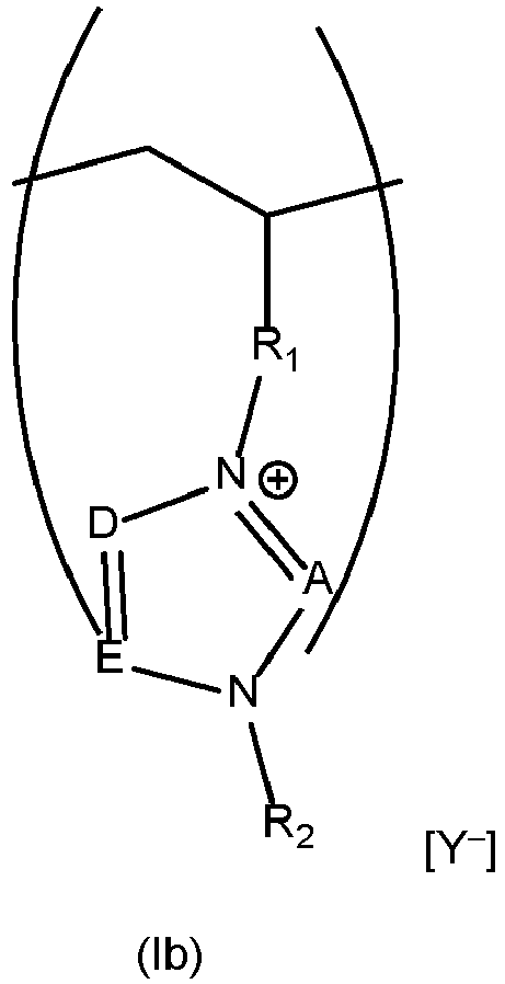
- a second type of monomeric unit of formula (lb):
- the first type of monomeric units and the second type of monomeric units being in a molar ratio of from 75:25 to 5:95;
and wherein - A, D and E are all CH; or A is N and D, E are both CH; or D is N and both A and E are CH; or E is N and both A and D are CH;
- Y- is an anion selected from the group consisting of triflate, mesylate, ethanesulfonate, benzenesulfonate, tosylate, bis(trifluoromethane)sulfonimide, tetrafluoroborate and hexafluorophosphate;
- R1 is a -(CH2)n- group wherein n is 1 to 6 or a group benzyl -(C6H4)-CH2-; and
- R2 is a C1-6 alkyl group.
-
As used herein the terms "poly-ionic liquid material" or "PIL material" or "poly-ionic liquid polymer" or "PIL polymer" refers to a polymer with monomeric units comprising ionic liquid cations as substitutions. In an analogous manner, the terms "poly-ionic liquid coating" or "PIL coating" refers to a poly-ionic liquid polymer which is applied as a coating film deposited onto the working electrode (metal/metal oxide-based) plate surface or as a coating deposited onto electrode substrate particles (metal/metal oxide-based particles or carbon-based particles), for example electrode substrate particles of a gas diffusion layer (GDL) support of a gas diffusion electrode (GDE).
-
Thanks to their structural characteristics, the copolymers of formula (I) allow using a water-based electrolyte as the solvent of CO2 reduction reaction electrolytic cells, with the aim to achieve a tunable, more sustainable and efficient electrochemical reactor for the CO2 conversion.
-
In some embodiments R1 is a -(CH2)n- group wherein n is 1 to 6, preferably n is 1 to 3, more preferably n is 1. In other embodiments R1 is a group benzyl -(C6H4)-CH2-.
-
In some embodiments R2 is a C1-6 alkyl group, notably a linear C1-6 alkyl group or a branched C3-6 alkyl group, preferably, R2 is selected from the group consisting of methyl, ethyl, propyl, isopropyl, butyl and tert-butyl, more preferably R2 is methyl, ethyl or butyl.
-
In some embodiments,
A, D and
E are all CH and the second type of monomeric unit of formula (lb) is a monomeric unit of formula (Ib1):
wherein
Y-, R
1 and R
2 are as defined in the claims and the present description.
-
In other embodiments
A is N and
D, E are both CH; and the second type of monomeric unit of formula (lb) is a monomeric unit of formula (Ib2):
wherein Y-, R
1 and R
2 are as defined in the claims and the present description
-
In some embodiments
A, D and E are all CH, R
1 is a group benzyl -(C
6H
4)-CH
2- and the second type of monomeric unit is a monomeric unit of formula (Ib3):
wherein Y-and R
2 are as defined in the claims and the present description, preferably Y- is triflate and R
2 is methyl, ethyl or butyl.
-
In some embodiments
A is N and
D, E are both CH; R
1 is a group benzyl -(C
6H
4)-CH
2- and the second type of monomeric unit is a monomeric unit of formula (Ib4):
wherein
Y- and R
2 are as defined in the claims and the present description, preferably
Y- is triflate and R
2 is methyl, ethyl or butyl.
-
In some embodiments the first type of monomeric units is obtained by polymerization of a first monomer type selected from the group consisting of styrene, acrylic acid, C
1-6 alkyl esters of acrylic acid, methacrylic acid and C
1-6 alkyl esters of methacrylic acid; preferably by polymerization of styrene, methacrylic acid or C
1-6 alkyl esters methacrylic acid. In some embodiments the first type of monomeric units is obtained by polymerization of styrene and has formula (la):
-
As used herein the term "plate" in relation to an "electrode plate" herein disclosed refers to a piece or object having a sheet form, i.e. a piece having two dimensions being significantly larger than a third dimension. In some embodiments the plate is a foil.
-
The electrode plate, is for example, a metal or a metal/metal oxide containing plate (for example a metal or metal/metal oxide foil) adequate for use in CO2 reduction reaction electrolytic cells. Depending on the product to be obtained, the electrode plate can be of various types. The skilled person is aware that the type of metal/metal oxide used as working electrode in an electrochemical cell influences the type of product obtained. In some embodiments, the electrode plate comprises or consists of Au, Pd, Ir. Pt, Rh, Co, Fe, Ni, Mo, Mn, Cu, Sn, Al, Bi, In, W, Se, Ag or Zn. In some embodiments the electrode plate comprises or consists of Ag or Zn.
-
In some embodiments the electrode plate is an Ag metal plate or a Zn metal plate, wherein said metal plate is coated with a polymeric coating made of a copolymer of formula (I) as defined in the present claims and specification. In some embodiments, the electrode comprises a metal plate comprising Ag, or consisting of Ag, coated with a polymeric coating made of a copolymer of formula (I), as disclosed in the present claims and description.
-
The terms "electrode substrate particles", "electrode particles", or "substrate particles" refer to metal/metal oxide-based particles or to carbon-based particles (sometimes forming a microporous layer, MPL) deposited on a porous layer, or gas diffusion layer (GDL), which is a self-standing conductive and porous substrate, so forming gas diffusion electrode (GDE). Thus, in some embodiments the porous layer comprising electrode substrate particles is a gas diffusion layer (GDL). The metal/metal oxide-based substrate particles are typically made of a metal or metal oxide containing for instance Ag, Zn, Au, Pd, Ir. Pt, Rh, Co, Fe, Ni, Mo, Mn, Cu, Sn, Al, Bi, In, W or Se, and the GDL is typically made of carbon-based particles in the form of carbon-fiber, carbon felt, carbon foam, carbon black powder, carbon-coated fluorinated membranes, or can be made of metal mesh's or metal foams of Ni, Cu, and may comprise other components such as fluorinated polymers.
-
In some embodiments the electrode herein disclosed in the present claims and description is a working electrode of an electrolytic cell. In particular, in some embodiments the electrode herein disclosed is a working electrode of an electrolytic cell to conduct CO2 reduction reaction.
-
In some embodiments the working electrode herein disclosed in the present claims and description is a gas diffusion electrode (GDE) comprising a GDL, which has a supporting role, comprising metal/metal oxide-based catalyst particles deposited on it. In some embodiments the working electrode herein disclosed in the present claims and description comprises an electrode plate. In some embodiments the electrode plate or the substrate particles (metal/metal oxide-based particles or to carbon-based particles) of gas diffusion electrode are coated with a polymeric coating made of a copolymer of formula (I) as defined in the present claims and specification.
-
Accordingly, another aspect herein disclosed refers to an electrolytic cell comprising an electrode as disclosed in the present claims and description. In some embodiments the electrolytic cell is a one compartment cell or a two compartment cells separated by a proton exchange membrane (PEM), an anion exchange membrane (AEM) or a bipolar membrane (BPM).
-
Yet another aspect herein disclosed refers to the use of a working electrode, or to the use of an electrolytic cell comprising said electrode, as disclosed in the present claims and description, to obtain CO2 reduction products. In particular, another aspect herein disclosed refers to a method to obtain CO2 reduction products, wherein said method comprises:
- placing a working electrode comprising an electrode plate, preferably a metal plate, coated with a polymeric coating made of a copolymer of formula (I), as disclosed in the present claims and description, in an electrolytic cell comprising an aqueous-based electrolyte saturated with CO2; or diffusing CO2 into a porous layer (e.g. a GDL) comprising electrode substrate particles (metal/metal oxide-based particles or/and carbon-based particles) coated with a polymeric coating made of a copolymer of formula (I), as disclosed in the present claims and description, in an electrolytic cell comprising an aqueous-based electrolyte;
- applying a potential during a period of time for conducting a chronoamperometry or a chronopotensiometry; and
- isolating the CO2 reduction products.
-
The aqueous-based electrolyte may be saturated with CO2 (at room temperature, i.e. between 15°C and 30°C, preferably between 20°C and 25°C).
-
The different CO2 products may be isolated or collected by any means known to the skilled person, such gas chromatography, high pressure liquid chromatography, head space gas chromatography, among others.
-
In some embodiments the electrolytic cell comprising an electrode as disclosed in the present claims and description further comprises an aqueous based electrolyte, a reference electrode and a counter electrode. In some embodiments the aqueous-based electrolyte is an aqueous solution containing at least 40%, preferably 50%, more preferably 60%, even more preferably 70% water, of one or more of compounds selected from the group consisting of KHCOs, CsHCO3, KOH, NaOH, CsOH and LiOH, among others. In some embodiments the counter electrode is a Pt counter electrode. In some embodiments the working electrode is an electrode comprising an Ag plate coated with a polymeric coating made of a copolymer of formula (I), as disclosed in the present claims and description, the reference electrode is an Ag/AgCI saturated reference electrode.
-
In some embodiments the electrolytic cell comprises a working electrode comprising an Ag plate, preferably an Ag foil, coated with a polymeric coating made of a copolymer of formula (I), as disclosed in the present claims and description, an Ag/AgCI saturated reference electrode, a Pt counter electrode and an aqueous-based electrolyte comprising KHCOs
-
The polymeric coatings made of copolymers of formula (I) herein disclosed are poly-ionic liquid materials which may be synthesized in a convenient manner and deposited in a controlled way onto an electrode plate, preferably a metal/metal oxide plate, of an electrode, or deposited in a controlled way onto electrode substrate particles, which may be metal/metal oxide-based particles and/or carbon-based particles, of a gas-diffusion electrode (GDE), ensuring in this manner a specific coating thickness and a certain ionic liquid-cation distribution.
-
The synthesis of the copolymers of formula (I) may be carried out by, either free radical polymerization or by controlled radical polymerization, for example using Nitroxide Mediated Polymerization (NMP), Reversible Addition Fragmentation Transfer chain (RAFT) or Macromolecular Design via the Interchange of Xanthates (MADIX). In some embodiments the copolymers of formula (I) are di/triblock copolymers, gradient copolymers or random copolymers.
-
In particular, some embodiments refer to a method for preparing an electrode comprising a metal plate or a porous layer comprising substrate particles, wherein the metal plate or the substrate particles are coated with a polymeric coating made of a copolymer of formula (I), as disclosed in the present claims and description, wherein said method comprises:
- polymerizing monomers of a first monomer type and a second monomer type, wherein the first monomer type is selected from the group consisting of styrene, acrylic acid, C1-6 alkyl esters of acrylic acid, methacrylic acid and C1-6 alkyl esters of methacrylic acid; and the second monomer type has formula (IIIc'):
to obtain a copolymer of formula (III) comprising monomeric units of formula (Illc):
- placing the copolymer of formula (III) in contact with a compound of formula (IIId):
in appropriate conditions to obtain a copolymer of formula (II) comprising monomeric units of formula (Ild):
- placing the copolymer of formula (II) in contact with an aqueous solution of a salt comprising an anion Y-to precipitate a copolymer of formula (I) comprising monomeric units of formula (lb):
- dissolving the copolymer of formula (I) in an appropriate solvent to obtain a solution comprising a concentration C of the copolymer of formula (I);
- coating an electrode plate or electrode substrate particles (metal/metal oxide-based particles or carbon-based particles) of a porous layer with a polymeric coating made of the copolymer of formula (I);
wherein X is a halide atom and R1, R2 and Y- are as defined in the present claims and description.
-
In some embodiments the coating step is carried out by dip coating, spray coating, spin coating, air brushing or doctor blade coating, among other techniques.
-
In some embodiments the coating step is carried out by dip coating and comprises:
- submerging a metal plate in the solution of the copolymer of formula (I); or submerging a porous layer comprising substrate particles in the solution of the copolymer of formula (I);
- withdrawing the metal plate or the porous layer from the solution of the copolymer of formula (I) at a certain withdraw speed U 0; and
- drying the metal plate or the porous layer
-
Another aspect of the disclosure refers thus to a working electrode obtainable by the method herein disclosed, in particular wherein said working electrode comprises a metal plate or a porous layer comprising substrate particles, wherein the metal plate or the substrate particles are coated with a polymeric coating having a thickness of between 5 nm and 225 nm; wherein the polymeric coating is made of a copolymer of formula (I) comprising a first type of monomeric units and a second type of monomeric units as defined in the claims and the present specification; and wherein the first type of monomeric units and the second type of monomeric units are in a molar ratio of from 75:25 to 5:95.
-
In some embodiments X is F, Cl, Br or I, preferably X is Cl.
-
In some embodiments
A, D and
E are all CH and the compound of formula (IIId) has formula (IIId1):
wherein R
2 is as defined in the claims and the present specification; and the monomeric units of formula (lb) obtained are:
wherein R
1 is as defined in the claims and the present specification.
-
In some embodiments
A is N and
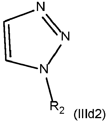
D, E are both CH and the compound of formula (IIId) has formula (Illd2):
wherein R
2 is as defined in the claims and the present specification; and the monomeric units of formula (lb) obtained are:
wherein R
1 is as defined in the claims and the present specification.
-
In some embodiments the polymerizing is carried out by controlled radical polymerization, for example using Nitroxide Mediated Polymerization (NMP), Reversible Addition Fragmentation Transfer chain (RAFT) or Macromolecular Design via the Interchange of Xanthates (MADIX). In some embodiments the polymerizing is carried out by radical polymerization.
-
In some embodiments the radical copolymerization is a nitroxide-mediated radical polymerization. In some embodiments the radical copolymerization is carried out in the absence of air at a constant temperature of between 60-150°C, preferably of between 110-125°C, for at least 1 h, preferably for at least 3 h.
-
In some embodiments, prior to the placing the copolymer of formula (III) in contact with a C1-6 N-alkylimidazole, the method comprises isolating and purifying the copolymer of formula (III) by precipitation in an appropriate solvent, preferably an alcohol, more preferably methanol; and optionally further comprises drying the copolymer of formula (III), preferably in a vacuum oven.
-
In some embodiments, the placing the copolymer of formula (III) in contact with a C1-6 N-alkylimidazole is carried out in the absence of air at a constant temperature of between 40-80°C, preferably between 50-70°C, for at least 24h, preferably for at least 48h.
-
In some embodiments, the placing the copolymer of formula (II) in contact with an aqueous solution of a salt comprising an anion Y - is carried out at room temperature by adding drop by drop the copolymer of formula (II) in the aqueous solution of a salt comprising an anion Y- to precipitate a copolymer of formula (I).
-
The specific choice of the anion Y- of the PIL copolymers of formula (I) herein disclosed also allows using said copolymers of formula (I) as coatings of metal electrodes used in electrolytic CO2 reduction cells with water-based electrolytes.
-
In some embodiments the anion Y - is an anion selected from the group consisting of triflate, mesylate, ethanesulfonate, benzenesulfonate, tosylate, bis(trifluoromethane)sulfonimide, tetrafluoroborate and hexafluorophosphate.
-
In some embodiments the anion Y - is triflate; R1 is -CH2- or benzyl, and R2 is selected from the group consisting of methyl, ethyl, propyl, isopropyl, butyl and tert-butyl.
-
In some embodiments, the copolymer of formula (I) is subsequently purified by dialysis in water.
-
In some embodiments the appropriate solvent of the dissolving the copolymer of formula (I) may be DMSO, THF, DMF or an alcohol such as methanol, ethanol or isopropanol among others, preferably methanol and the concentration C of the copolymer of formula (I) is between 0.5 to 5% wt, preferably of 1%wt of the copolymer of formula (I) relative to the total weight of the solution of the copolymer in the appropriate solvent.
-
In some embodiments the copolymer of formula (I) is a copolymer of styrene and vinylbenzyl C1-6 N-alkylimidazolium triflate or a vinylbenzyl C1-6 N-alkyltriazolium triflate. In some preferred embodiments the C1-6 N-alkylimidazolium is N-methylimidazolium, or N-ethylimidazolium, or N-propylimidazolium, or N-isopropylimidazolium, or N-butylimidazolium, among others. In some preferred embodiments the C1-6 N-alkyltriazolium is N-methyltriazolium, or N-ethyltriazolium, or N-propyltriazolium, or N-isopropyltriazolium, or N-butyltriazolium, among others
-
The specific structure of the copolymers of formula (I) allows for a controlled deposition of the PIL materials as a coating (i.e. as a PIL coating) onto an electrode plate (for instance, by dip-coating, spin coating, air brushing or spray coating, the plate in a solution of the copolymer of formula I) or onto substrate of a gas diffusion electrode which, in turn, makes possible controlling the specific thickness of the PIL coating on said metal electrode plates. Preferably the deposition is carried out by dip coating.
-
Indeed, in some embodiments the electrode plate is coated by submerging a metal plate in a solution of the copolymer of formula (I), or submerging a porous layer comprising electrode substrate particles in a solution of the copolymer of formula (I); and the resultant polymeric coating has a thickness according to an equation 1:
wherein h0 is the thickness, U0 the withdraw speed,
C the concentration of the solution of the copolymer of formula (I), η the viscosity of the solution, ρ the density of the solution and g the gravity constant.
-
In some embodiments the withdraw speed U0 is of between 0.5 to 20,000 µm/s, preferably of between 1 to 10,000 µm/s.
-
In other embodiments the electrode plate or the electrode substrate particles are coated by other coating methods (such as spray coating, spin coating, air brushing or doctor blade coating) and the specific thickness of the PIL coating is controlled with the concentration of the solution of the copolymer of formula (I).
-
In some embodiments, the solvent is an alcohol, preferably methanol.
-
In addition, the possibility of controlling the deposition of those PIL materials of formula (I) onto working electrodes, for use in electrolytic CO2 reduction cells, also allows controlling the thickness of the resulting PIL coatings. This controlled thickness allows, in turn, tuning the selectivity of the CO2 reduction reaction to different C1/C2/C2+ products.
-
Thus, in some embodiments, the polymeric coating of formula (I) has a thickness of between 7 to 225 nm, or of between 7 and 25 nm, or between 25 and 50 nm, or of between 15 and 25 nm, or of between 15 to 50 nm, or of between 20 to 50 nm, or of between 7 and 20 nm, or of between 7 and 15 nm. In other embodiments the polymeric coating of formula (I) has a thickness of between 5 and 7 nm. In yet other embodiments the polymeric coating of formula (I) has a thickness of between 50 and 150 nm, or of between 50 and 100 nm, or of between 100 and 225 nm.
-
Moreover, the hydrophobic/hydrophilic balance obtained with the specific ratios of the monomers used, as well as the monomeric distribution (block or random distribution) of the PIL copolymers of formula (I) herein disclosed, tuning the selectivity of the CO2 reduction reaction to specific C1/C2/C2+ products.
-
A polymer is a macromolecular compound which is obtained by reaction of one or more molecules which are called monomers, resulting after the reaction (by polymerization) of said monomers, to obtain a (macro)molecule with repeating monomeric units. When the polymer consists of only one type of monomeric units (i.e. is obtained by polymerization of only one monomer type, the polymer is a homopolymer, whereas when the polymer comprises more than one monomeric unit (i.e. is obtained with more than one monomer type), the polymer is a copolymer.
-
The term "block copolymer", as used herein, refers to a copolymer (thus comprising two or more monomeric units) comprising two or more homopolymer subunits linked by covalent bonds.
-
On the other hand, the term "random copolymer" or "statistical copolymer" as used herein, refers to a copolymer in which the probability of finding one of the two or more monomeric units in one point of the polymer chain is equal to the mole fraction of the monomer.
-
In some embodiments the copolymer of formula (I) is a block copolymer.
-
In some embodiments the copolymer of formula (I) is a block copolymer and the polymerizing step to obtain a copolymer of formula (III) comprises:
- polymerizing monomers of a first monomer type, wherein the first monomer type is selected from the group consisting of styrene, acrylic acid, C1-6 alkyl esters of acrylic acid, methacrylic acid and C1-6 alkyl esters of methacrylic acid; to obtain a polymer consisting of the first type of monomeric units;
- reacting the polymer consisting of the first type of monomeric units with monomers of formula (Illc') to obtain a block copolymer of formula (III);
wherein the first monomer type and second monomer type are in a weight ratio of from 75:25 to 5:95; and wherein the copolymer of formula (III), the copolymer of formula (I) and the monomers of formula (IIIc') are as defined in the claims and the present specification.
-
In some embodiments the copolymer of formula (I) is a random copolymer.
-
In some embodiments the copolymer of formula (I) is a random copolymer and the polymerizing step to obtain a copolymer of formula (III) comprises reacting in appropriate conditions a mixture of a first monomer type selected from the group consisting of styrene, acrylic acid, C1-6 alkyl esters of acrylic acid, methacrylic acid and C1-6 alkyl esters of methacrylic acid; and a second monomer type of formula (IIIc'); wherein the first monomer type and second monomer type are in a weight ratio of from 75:25 to 5:95 to obtain a random copolymer of formula (III).
-
Indeed, the ratio of the first type of monomeric units and the second type of monomeric units can also influence the hydrophilic and hydrophobic characteristics of the final copolymer of formula (I). The aforementioned characteristics regulate the interaction of the working electrode with the aqueous electrolyte favoring wettability and a greater number of protons at the electrode in the case of using a very hydrophilic polymer. Conversely, when the copolymer is more hydrophobic this would shield the active sites of the catalyst from contact with the aqueous electrolyte.
-
As shown and described in the examples, considering non imidazole functionalized electrodes (pure Ag and Ag coated with a comparative homopolymer of polystyrene - PS_Pure: POLY_0) had a value very close to 90° and, therefore, showed an almost completely hydrophobic behavior. Instead, the Ag electrode coated with POLY_3, which is a comparative homopolymer of PVBC functionalized with butylimidazolium triflate, showed a higher hydrophilicity, with a contact angle close to 76°. Then, by mixing PS (styrene) and PVBC (vinylbenzylchloride) and subsequently functionalize the obtained copolymers with N-butylimidazole, we expected to obtain coatings of exemplary copolymers of formula (I) with an increasing value of hydrophobicity as the percentage of the PS monomer inside the polymer increased. When the pure PVBC monomer amount increases in the polymer, the hydrophobic behavior of the final polymer increases. Indeed, the contact angle of the PS:PVBC functionalized copolymers after anion exchange ranges from 70 to 78°, showing their macroscopic hydrophobic character. This confirms that the hydrophobic/hydrophilic balance of the coatings remains a very important aspect to perform electrochemical CO2 conversion in aqueous media, other than the specific orientation of the monomeric units (such as the exemplary monomeric units of PS and PVBC) acquired during the copolymer deposition on the electrode plate or electrode substrate particles.
-
In addition, the random or block copolymer configuration appears to impact the CO2 reduction products obtained when coatings of copolymers of formula (I) are used, most probably because of the different 3D spatial conformations that the copolymers acquired depending on their chemical configuration (block or random). Indeed, a different CO2 reduction product selectivity could be due to due to the different spatial orientation or stacking of the polymers have inside the copolymer and the different orientation of the monomeric units with respect to the metal or substrate surface during their deposition. For example, in the exemplary copolymers of the examples, being the PS hydrophobic as the Ag, it is expected that the PS units are oriented close to the Ag surface. In a block copolymer, those units would be all in one side of the copolymer chain, while in a random configuration the PS monomer units are distributed in different positions inside the polymer chain. This may imply that random and block copolymers have a different porosity, tortuosity in the thickness of the polymeric films, which could imply different mass transport properties of the films and govern how CO2 and H+ species arrive to the metal catalyst surface for the reaction and the residence time that the reaction intermediates like CO stay inside the film, to be then converted to other C2 products like ethylene. Additionally, the different configuration (block or random) creates a different environment (superficial properties) at the catalyst-copolymer interface, where the CO2 electrochemical reduction reaction takes place.
-
For instance, as seen in the examples herein disclosed, an examplary coating of formula (I) comprising a ratio of 20:80 of monomeric units of formula (la) and monomeric units of formula (lb), provided different types and amounts of CO2 reduction products when the copolymer of formula (I) is a random or a block copolymer.
-
In addition, as seen in the examples herein disclosed, the ratio and type of the monomeric units of formula (la) and (lb) directly impacts the type and quantity of CO2 reduction products obtained. Indeed, the amount and distribution of the monomeric units of formula (la) and (lb) can act on the hydrophobic/hydrophilic characteristics of the polymer, on the adhesion of the polymer on the metal plate or to the substrate particles, or it can play a role on how the polymer chain arranges itself to compose the PIL coating.
-
Indeed, an Ag foil was coated with a random copolymer of formula (I) having a ratio of 20:80 of styrene and vinylbenzyl N-butylimidazolium triflate (N-butylimidazolium triflate substituted POLY_1), provided good yields for C1 and C2 gaseous products at 7 and 20 nm: the 7nm coating and 20nm coating showed Faradaic efficiencies (FE) applying -2V of FECH4≈25% (CH4) and FEC2H4≈5% (C2H4); and in terms of carbon containing liquid products a 20 nm coating resulted in FEAF≈3% (formic acid) and FEEtOH≈8% (ethanol). However, coatings with a block copolymer of formula (I) featuring also a ratio of 20:80 of styrene and vinylbenzyl N-butylimidazolium triflate (N-butylimidazolium triflate substituted POL_5), provided different results: a 7 nm coating provided a FECH4≈3% (CH4), whereas a 20 nm coating resulted only in the production of CO, and in terms of carbon containing liquid products a coating of 20 nm provided FEAF≈3% (formic acid) but no ethanol was detected.
-
Also on this point, coatings with a thickness of 20 nm made with a block copolymer of formula (I) having a ratio of 10:90 of styrene and vinylbenzyl N-butylimidazolium triflate (N-butylimidazolium triflate substituted POLY_6) produced a very high faradic efficiency towards ethanol (FEEtOH≈70%), whereas regarding gaseous products coatings of 7nm at -2V vs Ag/AgCI resulted in a FECH4≈20% and a FEC2H4≈5%. In contrast, coatings made with a random copolymer of formula (I) also having a ratio of 10:90 of styrene and vinylbenzyl N-butylimidazolium triflate (N-butylimidazolium triflate substituted POLY_4) produced, when using a 7 nm thickness, a faradic efficiency at 2V of FECH4≈5% and FEC2H4≈5%; whereas regarding liquid products of CO2 reduction only formic acid was obtained with a faradic efficiency of FEAF≈ 1.6% when a 7 nm coating was used, and FEAF≈ 2.6% when the thickness of the coating was 20 nm.
-
Moreover, coatings made with a random copolymer of formula (I) also having a ratio of 40:60 of styrene and vinylbenzyl N-butylimidazolium triflate (N-butylimidazolium triflate substituted POLY 2) produced, when using a 49nm thickness a faradic efficiency at 2V of FECH4≈5% and FEC2H4≈8%; whereas regarding liquid products of CO2 reduction the 49nm was particularly suited for the production of C1 to C3 alcohols featuring faradic efficiencies of 3% for formic acid, 0.6% for methanol, 18% for ethanol and 0.5% for 1-propanol.
-
In contrast, as seen in a comparative example herein disclosed featuring polymeric coatings in which all of the monomeric units have formula (lb) being functionalized with an imidazolium group (N-butylimidazolium triflate substituted POL_3) provided similar results to those obtained when no coating is applied, i.e. with pure silver.
-
Thus, the ratio of monomeric units of formula (la) and monomeric units of formula (lb), as well as their different distribution (random or block), and the thickness of the coating are three key factors affecting the amount and the type of carbon containing product obtained.
-
In some embodiments the monomeric units of formula (la) and the monomeric units of formula (lb), as defined in the present claims and specification, are in a molar ratio of from 50:50 to 5:95, preferably in a molar ratio of 40:60 to 10:90, for example in a molar ratio of 10:90, or 20:80 or 40:60.
-
In some embodiments the polymeric coating of formula (I) is a block copolymer of a thickness of between 7 and 25 nm, preferably of between 15 and 25 nm, more preferably of 20 nm, and the monomeric units of formula (la) and the monomeric units of formula (lb), as defined in the present claims and specification, are in a weight ratio of 10:90.
-
In some embodiments the polymeric coating of formula (I) is a block copolymer of a thickness of between 7 and 25 nm, preferably of between 7 and 15 nm, also preferably of 15 to 20 nm, also preferably of 7 nm or 20 nm, and the monomeric units of formula (Ia) and the monomeric units of formula (lb), as defined in the present claims and specification, are in a weight ratio of 20:80.
-
In other embodiments the polymeric coating of formula (I) is a random copolymer of a thickness of between 7 and 25 nm, preferably of between 7 and 15 nm, also preferably of 15 to 20 nm, also preferably of 7 nm or 20 nm, and the monomeric units of formula (la) and the monomeric units of formula (lb), as defined in the present claims and specification, are in a weight ratio of 10:90.
Brief Description of Drawings
-
Other features, details and advantages will be shown in the following detailed description and on the figures, on which:
- [ Fig. 1 ] Thicknesses of exemplary PILs coatings of copolymers of formula (I) obtained at different withdraw speeds (µm/s). In detail using a speed of 1; 10; 100; 250; 500; 1000; 5000; 10000 µm/s, thickness of 2; 7; 22; 35; 49; 70; 156; 221 nm were obtained, respectively.
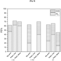
- [ Fig. 2 ] Faradaic efficiencies (FE) produced with coatings made with a comparative polystyrene homopolymer (POLY_0). FE were referred to gaseous products collected during chronoamperometry (CA) applying a fixed potential (E=-1,5V, -1,75V, -2V vs. Ag/AgCI) for a period of time (t= 15 min) using a CO2 saturated atmosphere. Results are shown for each thickness (L) of 7, 20 and 70 nm.
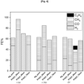
- [ Fig. 3 ] Faradaic efficiencies (FE) produced with exemplary coatings made with a copolymer obtained with 20% polystyrene and 80% polyvinylbenzylchloride in random configuration and functionalized with N-butylimidazolium triflate (POLY_1). Faradaic efficiencies (FE%) obtained with different thickness (2, 7,20, 35, 49, 70, 156 and 221 nm) were referred to gaseous products collected during CA (E=-1 ,5V, -1 ,75V, -2V vs. Ag/AgCI, t= 15 min, CO2 saturated atmosphere)
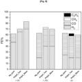
- [ Fig. 4 ] Faradaic efficiencies (FE) produced with exemplary coatings made with a copolymer obtained with 40% polystyrene and 60% polyvinylbenzylchloride in random configuration and functionalized with N-butylimidazolium triflate (POLY_2). Faradaic efficiencies (FE%) obtained with three different thickness (20, 49 and 70 nm) were referred to gaseous products collected during CA (E=-1 ,5V, -1 ,75V, -2V vs. Ag/AgCI, t= 15 min, CO2 saturated atmosphere)
- [ Fig. 5 ] Faradaic efficiencies (FE) produced with coatings made with a comparative homopolymer obtained with 100% polyvinylbenzylchloride functionalized with N-butylimidazolium triflate (POLY_3). Faradaic efficiencies (FE%) obtained with two different thickness (7 and 20 nm) were referred to gaseous products collected during CA (E=-1 ,5V, -1 ,75V, -2V vs. Ag/AgCI, t= 15 min, CO2 saturated atmosphere).
- [ Fig. 6 ] Faradaic efficiencies (FE) produced with exemplary coatings made with a copolymer obtained with 10% polystyrene and 90% polyvinylbenzylchloride in random configuration and functionalized with N-butylimidazolium triflate (POLY_4). Faradaic efficiencies (FE%) obtained with two different thickness (7 and 20 nm) were referred to gaseous products collected during CA E=-1,5V, -1 ,75V, -2V vs. Ag/AgCI, t= 15 min, CO2 saturated atmosphere).
- [ Fig. 7 ] Faradaic efficiencies (FE) produced with exemplary coatings made with a copolymer obtained with 20% polystyrene and 80% polyvinylbenzylchloride in block configuration and functionalized with N-butylimidazolium triflate (POLY_5). Faradaic efficiencies (FE%) obtained with two different thickness (7 and 20 nm) were referred to gaseous products collected during CA (E=-1,5V, -1 ,75V, -2V vs. Ag/AgCI, t= 15 min, CO2 saturated atmosphere).
- [ Fig. 8 ] Faradaic efficiencies (FE) produced with exemplary coatings made with a copolymer obtained with 10% polystyrene and 90% polyvinylbenzylchloride in block configuration and functionalized with N-butylimidazolium triflate (POLY_6). Faradaic efficiencies (FE%) obtained with two different thickness (7 and 20 nm) were referred to gaseous products collected during CA (E=-1,5V, -1 ,75V, -2V vs. Ag/AgCI, t= 15 min, CO2 saturated atmosphere)
Examples
-
General method: polymers skeletons based on Polystyrene (PS) and Polyvinylbenzyl chloride (PVBC) with different monomers ratios were synthesized, both in block and random configuration. Then, the obtained PS-PVBC copolymers were functionalized with imidazole as cation and triflate as anion to obtain exemplary PIL copolymers of formula (I). Subsequently, the so obtained PIL copolymers of formula (I) were deposited by dip-coating technique on silver foils and then tested in a single compartment electrochemical cell to assess the performance of the exemplary PILs-based Ag electrodes according to the present description in terms of selectivity and stability for the electrocatalytic CO2 reduction reaction.
1. Synthesis of copolymers of PS and PVBC - exemplary copolymers of formula (III):
-
Polystyrene and polyvinylbenzyl chloride monomers were used to obtain both random (r) and block (b) polymeric configurations using different molar ratios of styrene and vinylbenzyl chloride monomers, respectively. For comparative purposes, the homo-polymer of styrene (POLY_0) and of vinylbenzyl chloride (POLY_3) were also synthetized. Below, a summary of prepared polymers is reported in
Table 1:
Table 1: Schematic summary of all synthetized different homo-polymers and co-polymers. PS (polystyrene); PVBC (polyvinylbenzylchloride); r refers to random and b refers to block configuration. | Abbreviation | Monomers ratio in PILs |
| Poly_0 (comparative) | PS |
| Poly_1 | PS0.2-r-PVBC0.8 |
| Poly_2 | PS0.4-r-PVBC0.6 |
| Poly_3 (comparative) | PVBC |
| Poly_4 | PS0.1-r-PVBC0.9 |
| Poly_5 | PS0.2-b-PVBC0.8 |
| Poly_6 | PS0.1-b-PVBC0.9 |
1.1. Synthesis of exemplary random copolymers of formula (III):
-
PS-PVBC random co-polymers were synthetized by nitroxide-mediated radical polymerization (NMP). Both monomers, SG1 initiator and MAMA BlocBuilder alkoxyamine (2-({tert-butyl[[1-(diethoxyphosphoryl)-2,2- dimethylpropyl]amino}oxy)-2-methylpropanoic acid) were put in a round-bottom flask. Depending on the initial ratio of each monomer, different final polymer compositions were obtained (see Table 1). The flask was degassed with nitrogen and immersed in an oil bath to carry out the polymerization reaction (T=115°C, t=3h). The progress of the reaction was controlled by
1H-NMR. The random co-polymer was purified by precipitation in MeOH, filtered and dried in a vacuum oven. A scheme of reaction is showed in scheme 1:
1.2. Synthesis of exemplary block copolymers of formula
(III):
-
A two steps synthesis was used to prepare the block co-polymer. The first step included the synthesis of the first block of PS while the second step was the extension of the PS homopolymer with PVBC.
-
Firstly, the styrene monomer and the MAMA BlocBuilder alkoxyamine were dissolved in DMF in a round-bottom flask. The flask was degassed with nitrogen and immersed in an oil bath to carry out the polymerization reaction (T=115°C, t=3h). The homo-polymer polystyrene (PS) was purified by precipitation in MeOH, filtered and dried in a vacuum oven.
-
Secondly, PS-PVBC block polymers were also synthetized by NMP. The polystyrene, the vinylbenzyl chloride monomer and MAMA BlocBuilder alkoxyamine were put in a round-bottom flask. The flask was degassed with nitrogen and immersed in an oil bath to polymerization reaction. The progress of the reaction was controlled by 1H-NMR. The block co-polymer PS was purified by precipitation in MeOH, filtered and dried in a vacuum oven.
1.3. Cation functionalization - synthesis of exemplary copolymers of formula (II):
-
For the [BMIM]
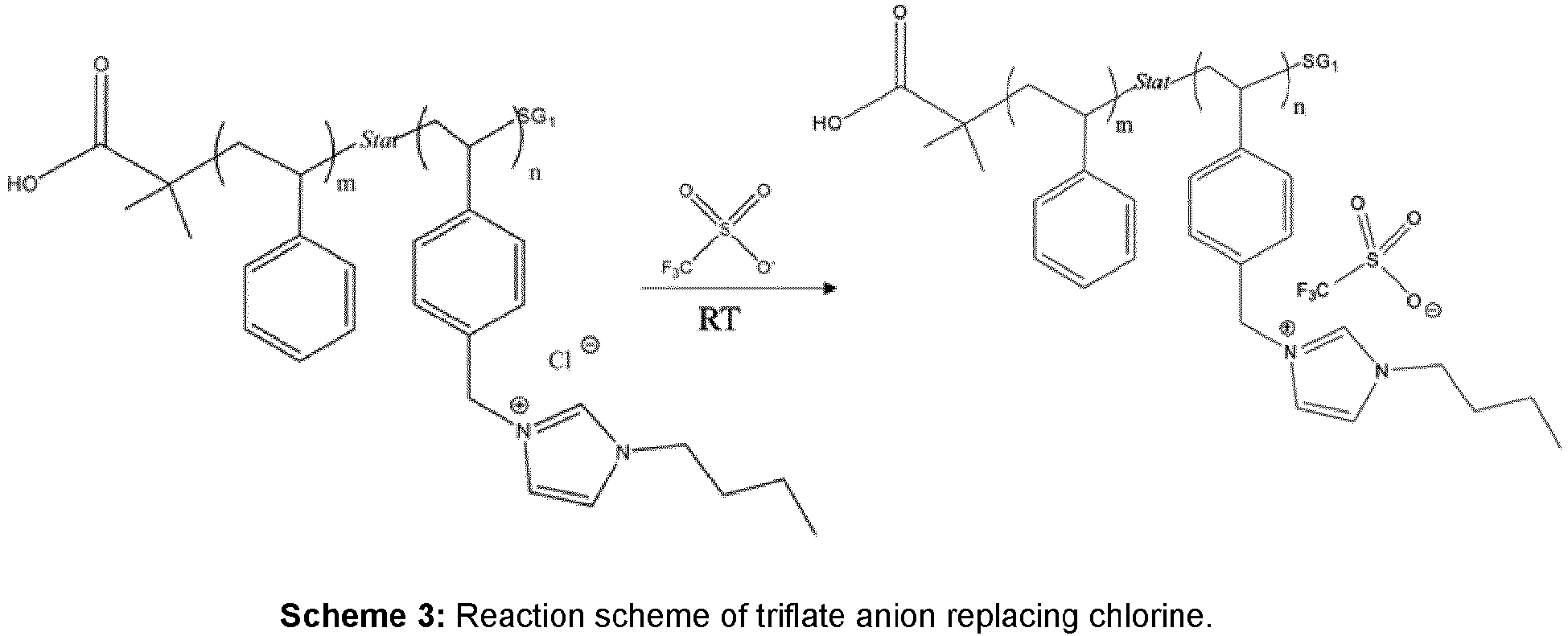
+ cation functionalization, the exemplary PS and PVBC co-polymers of formula (III) obtained, both in block and random configurations, were functionalized with 1-Butylimidazole chlorine by nucleophilic substitution reaction (SN), as schematized in Scheme 2:
-
The reaction occurred in monomeric units of PCVB in the Cl- position. Each polymer was mixed with 1-Butylimidazole and DMF in a round bottom flask. The flask was degassed with nitrogen and put in an oil bath to carry out the SN reaction (T=60°C, t=72h). The imidazole substitution was verified by 1H NMR. Each polymer with imidazole functionalization was purified by dialysis in water.
1.4. Anion exchange - synthesis of exemplary copolymers of formula (1):
-
The triflate anion [SO
3CF
3]
- exchange was performed by adding drop by drop the polymer functionalized with imidazole of formula (II), that was soluble in water, in a high concentrated solution of NaSO
3CF
3 in water (see scheme 3 below). When the exchange between chlorine and triflate occurs, the solubility of the polymer in water changes immediately. All the exemplary copolymers of formula (I) of the above table 1 with triflate anion are no longer soluble in aqueous solution. Thus, a white precipitate of the exemplary copolymers of formula (I) was formed, and subsequently filtered and dried in a vacuum oven.
2. Exemplary PIL copolymers of formula (I) deposition on silver foil
-
A solution (1% wt) of each polymer in MeOH was prepared. A dip-coater was used to homogenously deposit each PIL on a commercial silver foil in an active are of 1 cm
2. Dip coating is a process by which the substrate material, in this case the silver foil, is submerged in the PILs-MeOH solution, then taken out and allowed to drip dry. A theoretical formula (eq. 1) that directly links the thickness with the withdraw speed was used to foreseen the thickness of the polymeric film deposited on the silver foil.
wherein h
0 is the polymer thickness, U
0 the withdraw speed,
C the solution concentration, η the viscosity, ρ the density of the solution and g the gravity constant.
-
After coating the electrodes were left to air dry, in room pressure and temperature conditions.
-
Based on that, silver foil electrodes were casted with different PILs film thicknesses, which values are indicated in Fig. 1.
3. Electrocatalytic assays
-
A single compartment cell was used to perform the CO2 electrocatalytic reduction tests. A silver foil with PILs, an Ag/AgCI saturated and a Pt wire were employed as working, reference and counter electrodes, respectively. An aqueous-based electrolyte, as KHCO3=0.5M, was used and always kept under magnetic stirring. The cell presented a gas inlet and outlet. Through the first one, the pure gases from the cylinders (N2, CO2) were bubbled directly into the electrolyte; through the second one, the gases were sent to an in-line gas chromatograph with mass spectrometer (GC-MS).
-
The electrochemical protocols used for the tests consisted of first saturating with N2 the aqueous electrolyte to remove the air from the system and register the first linear sweep voltammetry (LSV), and then flushing CO2 until the electrolyte saturation to hence register a second LSV. Subsequently, three chronoamperometries (CA) were performed for each polymer by applying different potentials (E=-1.5V; -1.75V and -2V vs Ag/AgCI) in CO2 saturated atmosphere to investigate eventual variations on the selectivity to different CO2RR products or towards the H2 evolution reaction (HER).
3.1. POLY 0 (comparative coating) results and discussion
-
Poly_0 is a comparative polymer composed by pure polystyrene (see Table 1), without any PVBC and consequently without imidazole modification. In fact, as described in Scheme 2, the functionalization with imidazole takes place only in the VBC monomer units within the whole polymer thanks to the release of the Cl- group. It was deposited on the Ag foil with three different thicknesses: 7, 20 and 70 nm.
-
Figure 2 shows the efficiencies obtained for comparative coatings of pure polystirene (POLY_0) with thickness (L) of 7, 20, 70 nm in CO2 saturated atmosphere referred to the gaseous products collected during the assay (-2V vs. Ag/AgCI, 15 min). POLY_0 of 20 nm was also tested in N2 saturated atmosphere.
-
Comparing these four tests, PS coatings of 20nm in N2 produced only hydrogen (FEH2≈50%), as expected. Thus, HER seems to be the most favored reaction when using pure PS without any imidazole and triflate functionalization.
3.2. Exemplary coating of a copolymer of formula (I) - POLY 1 results and discussion
-
The exemplary copolymer of formula (I) POLY_1 was obtained with PS(20%) and PVBC(80%) in a random (R) configuration (see Table 1). Exemplary coatings of POLY_1 were deposited on the Ag foil with different thickness: 2, 7, 20, 35, 49, 70, 156 and 221 nm.
-
Figure 3 shows the faradic efficiencies (FE%) produced with exemplary coatings made of POLY_1 with thickness (L) of 2, 7, 20, 35, 49, 70, 156 and 221 nm, referred to the gaseous products collected during the CA (E=-1 ,5, -1,75, -2V vs. Ag/AgCI; 15 min each, CO2saturated atmosphere).
-
Analyzing the collected gaseous products, HER was clearly dominant with respect to CO formation at -1,5V vs. Ag/AgCI for each coating thickness during the first CA.
-
At E = -1,75V vs. Ag/AgCI the FEH2 was lower than at E = -1,5V vs. Ag/AgCI, while the FEco increased for each coating. An interesting aspect is that, at E= -1,75V vs Ag/AgCI , POLY_1 coatings of 20nm showed a FECH4≈5% and FEC2H4≈3%.
-
Gaseous products collected post CA at E = -2V vs. Ag/AgCI contained less hydrogen than at other potentials, with coatings of POLY_1 of 7nm and 20nm showing great FECH4≈25% and FEC2H4≈5%.
-
Liquid products of CO
2 reduction were collected before and after the 3 CAs, meaning that the amount of products, formic acid (FA) or ethanol (EtOH), could not be split for each applied potential, and thus a cumulative value is shown. For this reason, those values are reported separately and showed in
Table 2:
Table 2: cumulative Faradaic efficiencies (FE%) towards liquid products obtained after the three CAs with the Poly1 on the Ag foil. PS (polystyrene); PVBC (polyvinylbenzylchloride); FE (Faradic efficiency); FA (Formic acid); EtOH (ethanol) | POLY_1 : PS20%_R_PVBC80% |
| Thickness (nm) | 2 | 7 | 20 | 35 | 49 | 70 | 156 | 221 |
| FE% | FA | 5.00% | 0.30% | 3.00% | 2.00% | 4.40% | 3.60% | 5.00% | 3.60% |
| EtOH | | | 8.00% | 0.85% | 1.40% | | | |
3.3. Exemplary coating of a copolymer of formula (I) - POLY 2 results and discussion
-
The exemplary copolymer of formula (I) POLY_2 was obtained with PS(40%) and PVBC(60%) in a random (R) configuration (see Table 1). Exemplary coatings of POLY_2 were deposited on the Ag foil with three different thickness: 20, 49 and 70 nm.
-
Fig. 4 shows the faradaic efficiencies (FE%) produced with exemplary coatings made of POLY_2 with three different thickness (20, 49 and 70 nm) referred to gaseous products collected during CA (E = -1,5, -1,75, -2V vs. Ag/AgCI) 15 min each in CO2 saturated atmosphere.
-
Analyzing the collected gaseous products, HER was clearly dominant with respect to CO formation at E = -1,5V vs Ag/AgCI for each coating thickness during the first CA.
-
At E = -1,75V vs Ag/AgCI the FEH2 were lower than at E = -1,5V vs Ag/AgCI while the FEco increased for each coating.
-
Gaseous products collected post CA at -2V vs Ag/AgCI contained less hydrogen than at other applied potentials, and coatings of POLY_2 with 20nm thickness showed the lowest FEH2. Instead, at the highest applied potential, coatings of POLY_2 with 49nm thickness produced FECH4≈5% and FEC2H4≈8%.
-
Regarding the liquid products of the CO
2 reduction, the values are reported in Table 3 (for the same reasons explained for POLY_1). Less than 5% of formic acid (FA) was produced with all the thicknesses studied. Interestingly, coatings made with this exemplary copolymer promoted the production of C
1 to C
3 alcohols at the intermediate thickness of 49 nm, which is a unique result on Ag-based electrodes, which are generally known to be highly selective for the CO production.
Table 3: Cumulative Faradaic efficiencies towards liquid products obtained after the three CAs with POLY_2 coatings on the Ag foil. PS (polystyrene); PVBC (polyvinylbenzylchloride); FE (Faradic efficiency); FA (Formic acid), MeOH (methanol); EtOH (ethanol); 1Prop (1-propanol) | POLY_2: PS40%_R_PVBC60% |
| Thickness (nm) | 20 | 49 | 70 |
| FE% | FA | 2.40% | 3.00% | 4.00% |
| MeOH | | 0.60% | |
| EtOH | | 18.00% | 1.00% |
| 1Prop | | 0.50% | |
3.4. POLY 3 (comparative coating) results and discussion
-
The comparative homopolymer POLY_3 was obtained with PVBC 100% (see Table 1). It means that all monomeric units have imidazole functionalization, and no PS monomer is present. It was deposited on the Ag foil with two different thickness: 7 and 20 nm.
-
Figure 5 shows the efficiencies produced with comparative coatings obtained with the comparative homopolymer POLY_3 with thickness (L) of 7 and 20 nm in CO2 saturated atmosphere referred to the gaseous products collected during the assay (E = -2V vs. Ag/AgCI, 15 min).
-
As we can see in Figure 5, only H2 and CO were collected for POLY_3. In terms of FEco%, the two thicknesses provided similar results to the pure silver foil (without any PILs deposited on it). This shows that the percentage of PS plays a key role in the CO2 reduction products obtained. Indeed, it appears that the presence and quantity of styrene may act on the hydrophobic/hydrophilic characteristics of the polymer, on the adhesion of the polymer onto the Ag substrate or it may also play a role on how the polymer chains arrange themselves to form the coatings.
3.5. Exemplary coating of a copolymer of formula (I) - POLY 4 results and discussion
-
The exemplary copolymer of formula (I) POLY_4 was obtained with PS(10%) and PVBC(90%) in a random configuration (see Table 1). Exemplary coatings were deposited on the Ag foil with two different thickness: 7 and 20 nm.
-
Figure 6 shows the faradic efficiencies (FE) produced with exemplary coatings made of POLY_4 with two different thickness (7 and 20 nm) referred to gaseous products collected during CA (E = -1,5, -1,75, -2V vs. Ag/AgCI) 15 min each in CO2saturated atmosphere.
-
Analyzing the collected gaseous products, HER was clearly dominant with respect to CO formation at E = -1,5V for each POLY_4 coating thickness during the first CA.
-
At E = -1,75V vs Ag/AgCI FEH2 were lower than at E = -1,5V vs Ag/AgCI, while the FEco increased for each coating.
-
Gaseous products collected post CA at E = -2V vs Ag/AgCI contained less hydrogen than at other potentials. Coatings of POLY_4 of 7nm thickness showed an interesting FECH4≈5% both at E = -1,75V vs Ag/AgCI and E = -2V vs Ag/AgCI. At E = -2V vs Ag/AgCI coatings of POLY_4 with 7nm thickness showed FEC2H4≈5% as well.
-
Regarding liquid products of CO
2 reduction, the values are reported separately and shown in Table 4 (for the same reasons explained for POLY_1). In this case only formic acid was produced.
Table 4: Cumulative Faradaic efficiencies towards liquid products obtained after the three CAs with POLY_4 coatings on the Ag foil. PS (polystyrene); PVBC (polyvinylbenzylchloride); FE (Faradic efficiency); FA (Formic acid). | POLY_4 : PS10%_R_PVBC90% |
| Thickness (nm) | 7 | 20 |
| FE% | FA | 1.60% | 2.80% |
3.6. Exemplary coating of a copolymer of formula (I) - POLY 5 results and discussion
-
The exemplary copolymer of formula (I) POLY_5 was obtained with PS(20%) and PVBC(80%) in block configuration (see Table 1). Exemplary coatings were deposited on the Ag foil with two different thickness: 7 and 20 nm.
-
As we can see in
Figure 7 , H
2 and CO were the most common products. Exemplary coatings of POLY_5 of 7nm thickness produced slightly more CO (FE
CO%) than pure silver at -1,75 vs Ag/AgCI and E = -2V vs Ag/AgCI. Moreover, in both cases, exemplary coatings of POLY_5 of 7 nm showed FE
CH4≈3%. Liquid reduction products obtained are shown in Table 5 and only revealed the production of formic acid:
Table 5: Cumulative Faradaic efficiencies towards liquid products obtained after the three CAs with POLY_5 coatings on the Ag foil. PS (polystyrene); PVBC (polyvinylbenzylchloride); FE (Faradic efficiency); FA (Formic acid). | POLY_5 : PS20%_B_PVBC80% |
| Thickness (nm) | 7 | 20 |
| FE% | FA | 1.76% | 2.50% |
3.7. Exemplary coating of a copolymer of formula (I) - POLY 6 results and discussion
-
The exemplary copolymer of formula (I) POLY_6 was obtained with PS(10%) and PVBC(90%) in block configuration (see Table 1). Exemplary coatings were deposited on the Ag foil with two different thickness: 7 and 20 nm.
-
As reported in Figure 8 , H2 and CO were again the most common products at all applied potentials.
-
Exemplary coatings of POLY_6 of 7nm thickness at E = -2V vs Ag/AgCI presented the highest FE
CH4≈20% achieved with any of the coatings herein disclosed, and a good FE
C2H4≈5%. This high faradic efficiency towards methane reveals a more appropriate environment for the stabilization of the intermediates necessary for the generation of this product, starting from the CO
2 radical. Moreover, the appropriate exchange of protons and electrons, probably due to the appropriate thickness of the coating with 7 nm, allowed an efficient passage of water-based electrolyte and a good electron transport for the multiple steps reaction involved in the generation of methane, which requires 8 proton-coupled-electron transfer (PCET) processes. Moreover, exemplary coatings of POLY6 of 20nm thickness at E = -2V vs Ag/AgCI show the highest FE
CO% with respect to FE
H2%.
Table 6: Cumulative Faradaic efficiencies towards liquid products obtained after the three CAs with POLY_6 coatings on the Ag foil. PS (polystyrene); PVBC (polyvinylbenzylchloride); FE (Faradic efficiency); FA (Formic acid), EtOH (ethanol). | POLY_6 : PS10%_B_PVBC60% |
| Thickness (nm) | 7 | 20 |
| FE% | FA | 5.40% | 2.86% |
| EtOH | | 70.00% |
-
As seen in Table 6, the high faradic efficiency towards ethanol produced with exemplary coatings of POLY_6 appears to show that exemplary copolymers of formula (I) containing PS10% in block configuration favor an appropriate exchange of protons and a sufficient residence time of the CO produced by Ag on the polymeric matrix. The good exchange of protons and electrons is probably due to the appropriate thickness of the PIL, 20 nm which allows the passage of water-based electrolyte and a good conductivity of the electrode, which is required for the multiple steps reaction involved in the generation of ethanol (involving 12 e- and 12 H+). Moreover, at the interface between the polymer and the Ag active sites, *CO intermediates need stay the appropriate time for the subsequent coupling by *CO-*CO dimerization of *CHx-*CO reactions, hence favoring C-C bonds formation.
4. Contact angle measurement
-
Contact angle values were obtained by putting a drop of water on the PILs-coated Ag electrode surface.
-
Contact angle measurements were collected by putting a drop of MilliQ water on an Ag electrode surface without any coating (Ag_Pure), or coated with: a comparative coating of polystyrene (POLY_0, PS_Pure); a comparative coating of a homopolymer obtained with 100% polyvinylbenzylchloride functionalized with N-butylimidazolium triflate (POLY_3, PVBC_pure); an exemplary coating made with a copolymer obtained with 10% polystyrene and 90% polyvinylbenzylchloride in random configuration and functionalized with N-butylimidazolium triflate (POLY_4, PS_10_R); an exemplary coating made with a copolymer obtained with 10% polystirene and 90% polyvinylbenzylchloride in block configuration and functionalized with N-butylimidazolium triflate (POLY_6, PS_10_B); an exemplary coating made with a copolymer obtained with 20% polystirene and 80% polyvinylbenzylchloride in random configuration and functionalized with N-butylimidazolium triflate (POLY_1, PS_20_R); an exemplary coating made with a copolymer obtained with 20% polystirene and 80% polyvinylbenzylchloride in block configuration and functionalized with N-butylimidazolium triflate (POLY_5, PS_20_B); and an exemplary coating made with a copolymer obtained with 40% polystirene and 60% polyvinylbenzylchloride in random configuration and functionalized with N-butylimidazolium triflate (POLY_2, PS_40_R).
-
The electrodes were placed on the instrument plate horizontally, then deposited a MilliQ drop of water, and then acquired the image of the drop backlit by the light source. Then the program software from the acquired image calculated the contact angle between the water drop and the PILs in contact.
-
Considering non imidazole functionalized electrodes: pure Ag and Ag coated with a comparative homopolymer of polystyrene (PS_Pure: POLY_0) had a value very close to 90° and, therefore, showed an almost completely hydrophobic behavior. Instead, the Ag electrode coated with POLY_3, which is a comparative homopolymer of PVBC functionalized with butylimidazolium triflate, showed a higher hydrophilicity, with a contact angle close to 76°. Then, by mixing PS (styrene) and PVBC (vinylbenzylchloride) and subsequently functionalize the obtained copolymers with N-butylimidazole, we expected to obtain coatings of exemplary copolymers of formula (I) with an increasing value of hydrophobicity as the percentage of the PS monomer inside the polymer increased. When the pure PVBC monomer amount increases in the polymer, the hydrophobic behavior of the final polymer increases; probably because of interactions sites between PS-PVBC or due to the imidazole triflate modification. Indeed, it is worth mentioning that, during the synthesis, all the exemplary copolymers of formula (I) synthesized with different ratios of PS:PVBC, had very favorable hydrophilic interactions since they remained well soluble in water before the anion exchange. However, after anion exchange with a triflate anion, the polymer suddenly became insoluble in water and precipitated. Indeed, the contact angle of the PS:PVBC functionalized copolymers after anion exchange ranges from 70 to 78°, showing their macroscopic hydrophobic character. This confirms that the hydrophobic/hydrophilic balance of the coatings remains a very important aspect to perform electrochemical CO2 conversion in aqueous media, other than the specific orientation of the PS and PVBC units that every exemplary copolymer of formula (I) acquired during their deposition on the exemplary Ag electrode.







 the first type of monomeric units and the second type of monomeric units being in a molar ratio of from 75:25 to 5:95;
 - placing the copolymer of formula (III) in contact with a compound of formula (IIId):
 - placing the copolymer of formula (II) in contact with an aqueous solution of a salt comprising an anion Y-to precipitate a copolymer of formula (I) comprising monomeric units of formula (lb):
 - dissolving the copolymer of formula (I) in an appropriate solvent to obtain a solution comprising a concentration C of the copolymer of formula (I);- coating an electrode plate or electrode substrate particles (metal/metal oxide-based particles or carbon-based particles) of a porous layer with a polymeric coating made of the copolymer of formula (I);wherein X is a halide atom and R1, R2 and Y- are as defined in any of claims 1 to 7.