EP4491555A1 - Dust mitigation for optical position references system of an elevator system - Google Patents
Dust mitigation for optical position references system of an elevator system Download PDFInfo
- Publication number
- EP4491555A1 EP4491555A1 EP24187638.2A EP24187638A EP4491555A1 EP 4491555 A1 EP4491555 A1 EP 4491555A1 EP 24187638 A EP24187638 A EP 24187638A EP 4491555 A1 EP4491555 A1 EP 4491555A1
- Authority
- EP
- European Patent Office
- Prior art keywords
- duct
- hoistway
- airflow
- elevator car
- reference element
- Prior art date
- Legal status (The legal status is an assumption and is not a legal conclusion. Google has not performed a legal analysis and makes no representation as to the accuracy of the status listed.)
- Pending
Links
Images

Classifications
-
- B—PERFORMING OPERATIONS; TRANSPORTING
- B66—HOISTING; LIFTING; HAULING
- B66B—ELEVATORS; ESCALATORS OR MOVING WALKWAYS
- B66B1/00—Control systems of elevators in general
- B66B1/34—Details, e.g. call counting devices, data transmission from car to control system, devices giving information to the control system
- B66B1/3492—Position or motion detectors or driving means for the detector
-
- B—PERFORMING OPERATIONS; TRANSPORTING
- B66—HOISTING; LIFTING; HAULING
- B66B—ELEVATORS; ESCALATORS OR MOVING WALKWAYS
- B66B1/00—Control systems of elevators in general
- B66B1/02—Control systems without regulation, i.e. without retroactive action
- B66B1/06—Control systems without regulation, i.e. without retroactive action electric
-
- B—PERFORMING OPERATIONS; TRANSPORTING
- B08—CLEANING
- B08B—CLEANING IN GENERAL; PREVENTION OF FOULING IN GENERAL
- B08B5/00—Cleaning by methods involving the use of air flow or gas flow
- B08B5/02—Cleaning by the force of jets, e.g. blowing-out cavities
-
- B—PERFORMING OPERATIONS; TRANSPORTING
- B66—HOISTING; LIFTING; HAULING
- B66B—ELEVATORS; ESCALATORS OR MOVING WALKWAYS
- B66B11/00—Main component parts of lifts in, or associated with, buildings or other structures
- B66B11/02—Cages, i.e. cars
- B66B11/0226—Constructional features, e.g. walls assembly, decorative panels, comfort equipment, thermal or sound insulation
-
- B—PERFORMING OPERATIONS; TRANSPORTING
- B66—HOISTING; LIFTING; HAULING
- B66B—ELEVATORS; ESCALATORS OR MOVING WALKWAYS
- B66B3/00—Applications of devices for indicating or signalling operating conditions of elevators
- B66B3/02—Position or depth indicators
- B66B3/023—Position or depth indicators characterised by their mounting position
-
- B—PERFORMING OPERATIONS; TRANSPORTING
- B66—HOISTING; LIFTING; HAULING
- B66B—ELEVATORS; ESCALATORS OR MOVING WALKWAYS
- B66B5/00—Applications of checking, fault-correcting, or safety devices in elevators
- B66B5/0006—Monitoring devices or performance analysers
- B66B5/0018—Devices monitoring the operating condition of the elevator system
-
- B—PERFORMING OPERATIONS; TRANSPORTING
- B66—HOISTING; LIFTING; HAULING
- B66B—ELEVATORS; ESCALATORS OR MOVING WALKWAYS
- B66B5/00—Applications of checking, fault-correcting, or safety devices in elevators
- B66B5/0087—Devices facilitating maintenance, repair or inspection tasks
Definitions
- Exemplary embodiments pertain to the art of elevator systems, and in particular to a position reference system (PRS) of an elevator system.
- PRS position reference system
- Elevator systems often include a position reference systems (PRS), which is utilized to determine a position of an elevator car in the hoistway.
- PRS position reference systems
- the PRS is an optical system in which an information tape is vertically installed in the hoistway, and is read by an optical sensor mounted on the elevator car to determine the position of the elevator car in the hoistway.
- Hoistway environments can be dusty which interferes with the function of the optical sensor.
- a position reference system of an elevator system includes a reference element having a fixed position in a hoistway of the elevator system, and an optical sensor configured to move along the hoistway with an elevator car of the elevator system and configured to transmit a signal to the reference element to determine the position of the elevator car.
- An airflow duct is configured to move along the hoistway with the elevator car. The airflow duct is configured to passively direct an airflow toward the reference element to prevent accumulation of particles on the reference element.
- Particular embodiments further may include at least one, or a plurality of, the following optional features, alone or in combination with each other:
- the airflow duct includes a duct body, one or more duct inlets located at one or more of a first duct end and a second duct end, and one or more duct outlets located along the duct body between the first duct end and the second duct end.
- the one or more duct outlets are configured to direct the airflow out of the airflow duct and toward the reference element.
- the one or more duct inlets are vertically downwardly facing when in an installed position on the elevator car.
- the one or more duct inlets are upwardly facing when in an installed position on the elevator car.
- the reference element is a coded tape.
- the airflow duct is positioned vertically below the optical sensor.
- an elevator system in another exemplary embodiment, includes a hoistway, an elevator car positioned in the hoistway and movable along the length of the hoistway, and a position reference system located in the hoistway and configured to determine a position of the elevator car in the hoistway.
- the position reference system includes a reference element having a fixed position in the hoistway, and an optical sensor configured to move along the hoistway with the elevator car and configured to transmit a signal to the reference element to determine the position of the elevator car.
- An airflow duct is configured to move along the hoistway with the elevator car. The airflow duct is configured to passively direct an airflow toward the reference element to prevent accumulation of particles on the reference element.
- Particular embodiments further may include at least one, or a plurality of, the following optional features, alone or in combination with each other:
- the airflow duct includes a duct body, one or more duct inlets located at one or more of a first duct end and a second duct end, and one or more duct outlets located along the duct body between the first duct end and the second duct end.
- the one or more duct outlets are configured to direct the airflow out of the airflow duct and toward the reference element.
- the one or more duct inlets are vertically downwardly facing when in an installed position on the elevator car.
- the one or more duct outlets are vertically upward facing when in an installed position on the elevator car.
- the reference element is a coded tape.
- the airflow duct is positioned vertically above the optical sensor.
- the airflow duct is positioned vertically below the optical sensor.
- a method of operating an elevator system includes moving an elevator car along a hoistway, and determining a position of the elevator car in the hoistway via a position reference system.
- the position reference system includes a reference element fixed in the hoistway, and an optical sensor configured to move along the hoistway with the elevator car and configured to transmit a signal to the reference element to determine the position of the elevator car.
- An airflow is passively urged toward the reference element via movement of the elevator car along the hoistway to prevent accumulation of particles on the reference element.
- Particular embodiments further may include at least one, or a plurality of, the following optional features, alone or in combination with each other:
- the airflow is urged toward the reference element via an airflow duct located at the elevator car and moveable along the hoistway therewith.
- the airflow duct includes a duct body, one or more duct inlets located at one or more of a first duct end and a second duct end, and one or more duct outlets located along the duct body between the first duct end and the second duct end, the one or more duct outlets configured to direct the airflow out of the airflow duct and toward the reference element.
- the elevator car is moved downwardly in the hoistway to urge the airflow toward the reference element.
- the one or more duct inlets are vertically downwardly facing when in an installed position on the elevator car.
- the reference element is a coded tape.
- the airflow duct is positioned vertically above the optical sensor.
- FIG. 1 is a perspective view of an elevator system 101 including an elevator car 103, a counterweight 105, a tension member 107, a guide rail 109, a machine 111, a position reference system 113, and a controller 115.
- the elevator car 103 and counterweight 105 are connected to each other by the tension member 107.
- the tension member 107 may include or be configured as, for example, ropes, steel cables, and/or coated-steel belts.
- the counterweight 105 is configured to balance a load of the elevator car 103 and is configured to facilitate movement of the elevator car 103 concurrently and in an opposite direction with respect to the counterweight 105 within an elevator shaft or hoistway 117 and along the guide rail 109.
- the tension member 107 engages the machine 111, which is part of an overhead structure of the elevator system 101.
- the machine 111 is configured to control movement between the elevator car 103 and the counterweight 105.
- the controller 115 may be located, as shown, in a controller room 121 of the hoistway 117 and is configured to control the operation of the elevator system 101, and particularly the elevator car 103. It is to be appreciated that the controller 115 need not be in the controller room 121 but may be in the hoistway or other location in the elevator system.
- the controller 115 may provide drive signals to the machine 111 to control the acceleration, deceleration, leveling, stopping, etc. of the elevator car 103.
- the controller 115 may also be configured to receive position signals from the position reference system 113 or any other desired position reference device. When moving up or down within the hoistway 117 along guide rail 109, the elevator car 103 may stop at one or more landings 125 as controlled by the controller 115. Although shown in a controller room 121, those of skill in the art will appreciate that the controller 115 can be located and/or configured in other locations or positions within the elevator system 101. In one embodiment, the controller 115 may be located remotely or in a distributed computing network (e.g., cloud computing architecture). The controller 115 may be implemented using a processor-based machine, such as a personal computer, server, distributed computing network, etc.
- the machine 111 may include a motor or similar driving mechanism.
- the machine 111 is configured to include an electrically driven motor.
- the power supply for the motor may be any power source, including a power grid, which, in combination with other components, is supplied to the motor.
- the machine 111 may include a traction sheave that imparts force to tension member 107 to move the elevator car 103 within hoistway 117.
- the elevator system 101 also includes one or more elevator doors 104.
- the elevator door 104 may be attached to the elevator car 103 or the elevator door 104 may be located on a landing 125 of the elevator system 101, or both. Embodiments disclosed herein may be applicable to both an elevator door 104 attached to the elevator car 103 or an elevator door 104 located on a landing 125 of the elevator system 101, or both.
- the elevator door 104 opens to allow passengers to enter and exit the elevator car 103.
- the position reference system 113 includes a reference element, such as a coded tape 200 extending along a vertical length of the hoistway 117 and fixed in the hoistway 117.
- the tape 200 is coded with information imprinted on or embedded in the tape 200, which when read by an optical sensor 202 indicates the vertical position of the elevator car 103 in the hoistway 117.
- the optical sensor 202 is disposed at the elevator car 103 and travels along the hoistway 117 with the elevator car 103.
- the optical sensor 202 is located at, for example, a roof 208 of the elevator car 103.
- the tape 200 is formed from, for example, a metal or plastic material.
- the tape 200 is secured in the hoistway 117 via a plurality of guide clips 204 along the hoistway 117 and tension locks 206 configured to maintain a selected tension on the tape 200.
- the tension locks 206 are located at a vertically upper end of the tape 200 and at a vertically lower end (not shown in Fig.) of the tape 200.
- the optical sensor 202 may be, for example a dual camera sensor including a light source (not shown). To determine the position, the tape 200 is illuminated by the light source, which emits, for example, one or more short infrared pulses. When the tape 200 is illuminated, the optical sensor 202 records a pattern on the tape 200 in front of optical sensor 202. The optical sensor 202 communicates a signal to the controller 115 that is indicative of the pattern read by the optical sensor 202, and the controller 115 determines the position of the elevator car 103.
- an airflow duct 210 is mounted on the elevator car 103.
- the airflow duct 210 includes one or more duct inlets 212, and one or more duct outlets 214 to direct an airflow 216 toward the tape 200 to remove any accumulated dust or other particles from the tape 200.
- the airflow duct 210 is, for example, U-shaped and has two duct inlets 212, with a duct inlet 212 located at each of a first duct end 218 and at a second duct end 220 opposite the first duct end 218.
- the airflow duct 210 may be formed from a material such as a plastic, metal or composite material.
- the one or more duct outlets 214 are located along a duct body 222 between the first duct end 218 and the second duct end 220, and are configured and oriented to direct the airflow 216 toward the tape 200.
- the airflow duct 210 has a constant, circular cross-section, while in other embodiments shown in Figure 4 the cross-sectional shape and/or size of the airflow duct 210 cross-section may vary between the one or more duct inlets 212 and the one or more duct outlets 214 to provide desired properties of the airflow 216, such as airflow pressure or flow rate.
- the cross-section of the airflow duct 210 may be a converging configuration such that the cross-sectional area of the airflow duct 210 is greater at the one or more duct inlets 212 than at or near the one or more duct outlets 214.
- the one or more duct outlets 214 are located, in some embodiments, at a midpoint portion of the duct body 222.
- the one or more duct outlets 214 are three duct outlets 214 arrayed in a linear arrangement substantially horizontally across the tape 200.
- the duct outlets 214 may be configured to direct the airflow 216 in substantially parallel streams out of the duct outlets 214.
- the duct outlets 214 are circular, while in other embodiments, the duct outlets 214 may have other shapes, such as elliptical, quadrilateral (illustrated in FIG. 4 ) or oval shaped.
- the duct outlets 214 may have other arrangements, such as, for example, holes, slits or protruding nozzle structures, to provide selected characteristics of the airflow 216.
- the airflow duct 210 is located at the elevator car 103, and travels with the elevator car 103 along the hoistway 117.
- the airflow duct 210 is positioned on the elevator car 103 such that the duct inlets 212 are located vertically below the duct outlets 214, and further may be positioned such that the duct outlets 214 are vertically above the optical sensor 202.
- the downward travel of the elevator car 103 urges the airflow 216 into the airflow duct 210 via the duct inlets 212, which face vertically downwardly when the airflow duct 210 is in the installed position, as shown in FIG. 2 .
- the airflow 216 is then directed along the duct body 222 and out through the duct outlets 214 toward the tape 200.
- the airflow 216 directed toward the tape 200 dislodges and removes dust and other particles from the tape 200, which improves operation of the position reference system 113.
- the airflow duct 210 provides cleaning of the tape 200 passively, without requiring additional power, other than that required to move the elevator car 103 along the hoistway 117. Further, orientation of the duct inlets 212 downwardly prevents the accumulation of dust in the airflow duct 210 when the elevator car 103 is stationary. Alternatively, the air duct inlet 212 may be located in an upward direction to urge airflow while the car 103 travels upwardly in the hoistway 117. To prevent accumulation of dust within the airflow duct 210, a porous filter (not illustrated) may be installed at the opening 212 to prevent accumulation of dust within the airflow duct 210.
Landscapes
- Engineering & Computer Science (AREA)
- Automation & Control Theory (AREA)
- Computer Networks & Wireless Communication (AREA)
- Civil Engineering (AREA)
- Mechanical Engineering (AREA)
- Structural Engineering (AREA)
- Lift-Guide Devices, And Elevator Ropes And Cables (AREA)
- Cage And Drive Apparatuses For Elevators (AREA)
Abstract
Description
- Exemplary embodiments pertain to the art of elevator systems, and in particular to a position reference system (PRS) of an elevator system.
- Elevator systems often include a position reference systems (PRS), which is utilized to determine a position of an elevator car in the hoistway. In some elevator systems, the PRS is an optical system in which an information tape is vertically installed in the hoistway, and is read by an optical sensor mounted on the elevator car to determine the position of the elevator car in the hoistway. Hoistway environments, however, can be dusty which interferes with the function of the optical sensor.
- In one exemplary embodiment, a position reference system of an elevator system includes a reference element having a fixed position in a hoistway of the elevator system, and an optical sensor configured to move along the hoistway with an elevator car of the elevator system and configured to transmit a signal to the reference element to determine the position of the elevator car. An airflow duct is configured to move along the hoistway with the elevator car. The airflow duct is configured to passively direct an airflow toward the reference element to prevent accumulation of particles on the reference element.
- Particular embodiments further may include at least one, or a plurality of, the following optional features, alone or in combination with each other:
- Additionally or alternatively, in this or other embodiments, the airflow duct includes a duct body, one or more duct inlets located at one or more of a first duct end and a second duct end, and one or more duct outlets located along the duct body between the first duct end and the second duct end. The one or more duct outlets are configured to direct the airflow out of the airflow duct and toward the reference element.
- Additionally or alternatively, in this or other embodiments, the one or more duct inlets are vertically downwardly facing when in an installed position on the elevator car.
- Additionally or alternatively, in this or other embodiments, the one or more duct inlets are upwardly facing when in an installed position on the elevator car.
- Additionally or alternatively, in this or other embodiments, the reference element is a coded tape.
- Additionally or alternatively, in this or other embodiments, the airflow duct is positioned vertically above the optical sensor.
- Additionally or alternatively, in this or other embodiments, the airflow duct is positioned vertically below the optical sensor.
- In another exemplary embodiment, an elevator system includes a hoistway, an elevator car positioned in the hoistway and movable along the length of the hoistway, and a position reference system located in the hoistway and configured to determine a position of the elevator car in the hoistway. The position reference system includes a reference element having a fixed position in the hoistway, and an optical sensor configured to move along the hoistway with the elevator car and configured to transmit a signal to the reference element to determine the position of the elevator car. An airflow duct is configured to move along the hoistway with the elevator car. The airflow duct is configured to passively direct an airflow toward the reference element to prevent accumulation of particles on the reference element.
- Particular embodiments further may include at least one, or a plurality of, the following optional features, alone or in combination with each other:
- Additionally or alternatively, in this or other embodiments, the airflow duct includes a duct body, one or more duct inlets located at one or more of a first duct end and a second duct end, and one or more duct outlets located along the duct body between the first duct end and the second duct end. The one or more duct outlets are configured to direct the airflow out of the airflow duct and toward the reference element.
- Additionally or alternatively, in this or other embodiments, the one or more duct inlets are vertically downwardly facing when in an installed position on the elevator car.
- Additionally or alternatively, in this or other embodiments, the one or more duct outlets are vertically upward facing when in an installed position on the elevator car.
- Additionally or alternatively, in this or other embodiments, the reference element is a coded tape.
- Additionally or alternatively, in this or other embodiments, the airflow duct is positioned vertically above the optical sensor.
- Additionally or alternatively, in this or other embodiments, the airflow duct is positioned vertically below the optical sensor.
- In yet another exemplary embodiment, a method of operating an elevator system includes moving an elevator car along a hoistway, and determining a position of the elevator car in the hoistway via a position reference system. The position reference system includes a reference element fixed in the hoistway, and an optical sensor configured to move along the hoistway with the elevator car and configured to transmit a signal to the reference element to determine the position of the elevator car. An airflow is passively urged toward the reference element via movement of the elevator car along the hoistway to prevent accumulation of particles on the reference element.
- Particular embodiments further may include at least one, or a plurality of, the following optional features, alone or in combination with each other:
- Additionally or alternatively, in this or other embodiments, the airflow is urged toward the reference element via an airflow duct located at the elevator car and moveable along the hoistway therewith. The airflow duct includes a duct body, one or more duct inlets located at one or more of a first duct end and a second duct end, and one or more duct outlets located along the duct body between the first duct end and the second duct end, the one or more duct outlets configured to direct the airflow out of the airflow duct and toward the reference element.
- Additionally or alternatively, in this or other embodiments, the elevator car is moved downwardly in the hoistway to urge the airflow toward the reference element.
- Additionally or alternatively, in this or other embodiments, the one or more duct inlets are vertically downwardly facing when in an installed position on the elevator car.
- Additionally or alternatively, in this or other embodiments, the reference element is a coded tape.
- Additionally or alternatively, in this or other embodiments, the airflow duct is positioned vertically above the optical sensor.
- The following descriptions should not be considered limiting in any way. With reference to the accompanying drawings, like elements are numbered alike:
-
FIG. 1 is a schematic illustration of an embodiment of an elevator system; -
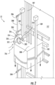
FIG. 2 is a schematic illustration of an embodiment of a position reference system of an elevator system; -
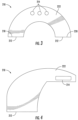
FIG. 3 is an illustration of an embodiment of an airflow duct of a position reference system; and -
FIG. 4 is an illustration of another embodiment of an airflow duct of a position reference system. - A detailed description of one or more embodiments of the disclosed apparatus and method are presented herein by way of exemplification and not limitation with reference to the Figures.
-
FIG. 1 is a perspective view of anelevator system 101 including anelevator car 103, acounterweight 105, atension member 107, aguide rail 109, amachine 111, aposition reference system 113, and acontroller 115. Theelevator car 103 andcounterweight 105 are connected to each other by thetension member 107. Thetension member 107 may include or be configured as, for example, ropes, steel cables, and/or coated-steel belts. Thecounterweight 105 is configured to balance a load of theelevator car 103 and is configured to facilitate movement of theelevator car 103 concurrently and in an opposite direction with respect to thecounterweight 105 within an elevator shaft orhoistway 117 and along theguide rail 109. - The
tension member 107 engages themachine 111, which is part of an overhead structure of theelevator system 101. Themachine 111 is configured to control movement between theelevator car 103 and thecounterweight 105. Thecontroller 115 may be located, as shown, in acontroller room 121 of thehoistway 117 and is configured to control the operation of theelevator system 101, and particularly theelevator car 103. It is to be appreciated that thecontroller 115 need not be in thecontroller room 121 but may be in the hoistway or other location in the elevator system. For example, thecontroller 115 may provide drive signals to themachine 111 to control the acceleration, deceleration, leveling, stopping, etc. of theelevator car 103. Thecontroller 115 may also be configured to receive position signals from theposition reference system 113 or any other desired position reference device. When moving up or down within thehoistway 117 alongguide rail 109, theelevator car 103 may stop at one ormore landings 125 as controlled by thecontroller 115. Although shown in acontroller room 121, those of skill in the art will appreciate that thecontroller 115 can be located and/or configured in other locations or positions within theelevator system 101. In one embodiment, thecontroller 115 may be located remotely or in a distributed computing network (e.g., cloud computing architecture). Thecontroller 115 may be implemented using a processor-based machine, such as a personal computer, server, distributed computing network, etc. - The
machine 111 may include a motor or similar driving mechanism. In accordance with embodiments of the disclosure, themachine 111 is configured to include an electrically driven motor. The power supply for the motor may be any power source, including a power grid, which, in combination with other components, is supplied to the motor. Themachine 111 may include a traction sheave that imparts force totension member 107 to move theelevator car 103 withinhoistway 117. - The
elevator system 101 also includes one ormore elevator doors 104. Theelevator door 104 may be attached to theelevator car 103 or theelevator door 104 may be located on alanding 125 of theelevator system 101, or both. Embodiments disclosed herein may be applicable to both anelevator door 104 attached to theelevator car 103 or anelevator door 104 located on alanding 125 of theelevator system 101, or both. Theelevator door 104 opens to allow passengers to enter and exit theelevator car 103. - Referring now to
FIG. 2 , theposition reference system 113 includes a reference element, such as acoded tape 200 extending along a vertical length of thehoistway 117 and fixed in thehoistway 117. Thetape 200 is coded with information imprinted on or embedded in thetape 200, which when read by anoptical sensor 202 indicates the vertical position of theelevator car 103 in thehoistway 117. Theoptical sensor 202 is disposed at theelevator car 103 and travels along thehoistway 117 with theelevator car 103. Theoptical sensor 202 is located at, for example, aroof 208 of theelevator car 103. In some embodiments, thetape 200 is formed from, for example, a metal or plastic material. Thetape 200 is secured in thehoistway 117 via a plurality of guide clips 204 along thehoistway 117 andtension locks 206 configured to maintain a selected tension on thetape 200. The tension locks 206 are located at a vertically upper end of thetape 200 and at a vertically lower end (not shown in Fig.) of thetape 200. - The
optical sensor 202 may be, for example a dual camera sensor including a light source (not shown). To determine the position, thetape 200 is illuminated by the light source, which emits, for example, one or more short infrared pulses. When thetape 200 is illuminated, theoptical sensor 202 records a pattern on thetape 200 in front ofoptical sensor 202. Theoptical sensor 202 communicates a signal to thecontroller 115 that is indicative of the pattern read by theoptical sensor 202, and thecontroller 115 determines the position of theelevator car 103. - Dust and other particles in the hoistway may accumulate on the
tape 200, which may interfere with operation of theoptical sensor 202. To alleviate this issue, anairflow duct 210 is mounted on theelevator car 103. Theairflow duct 210 includes one ormore duct inlets 212, and one ormore duct outlets 214 to direct anairflow 216 toward thetape 200 to remove any accumulated dust or other particles from thetape 200. - Referring now to
FIG. 3 , theairflow duct 210 is, for example, U-shaped and has twoduct inlets 212, with aduct inlet 212 located at each of afirst duct end 218 and at asecond duct end 220 opposite thefirst duct end 218. Theairflow duct 210 may be formed from a material such as a plastic, metal or composite material. The one ormore duct outlets 214 are located along aduct body 222 between thefirst duct end 218 and thesecond duct end 220, and are configured and oriented to direct theairflow 216 toward thetape 200. In some embodiments, theairflow duct 210 has a constant, circular cross-section, while in other embodiments shown inFigure 4 the cross-sectional shape and/or size of theairflow duct 210 cross-section may vary between the one ormore duct inlets 212 and the one ormore duct outlets 214 to provide desired properties of theairflow 216, such as airflow pressure or flow rate. For example, as shown inFigure 4 , the cross-section of theairflow duct 210 may be a converging configuration such that the cross-sectional area of theairflow duct 210 is greater at the one ormore duct inlets 212 than at or near the one ormore duct outlets 214. - Referring again to
FIG. 3 , the one ormore duct outlets 214 are located, in some embodiments, at a midpoint portion of theduct body 222. In some embodiments, the one ormore duct outlets 214 are threeduct outlets 214 arrayed in a linear arrangement substantially horizontally across thetape 200. Theduct outlets 214 may be configured to direct theairflow 216 in substantially parallel streams out of theduct outlets 214. In some embodiments theduct outlets 214 are circular, while in other embodiments, theduct outlets 214 may have other shapes, such as elliptical, quadrilateral (illustrated inFIG. 4 ) or oval shaped. One skilled in the art, however, will readily appreciate that the configuration described herein is merely exemplary, and that in other configurations theduct outlets 214 may have other arrangements, such as, for example, holes, slits or protruding nozzle structures, to provide selected characteristics of theairflow 216. - Referring again to
FIG. 2 , theairflow duct 210 is located at theelevator car 103, and travels with theelevator car 103 along thehoistway 117. In some embodiments theairflow duct 210 is positioned on theelevator car 103 such that theduct inlets 212 are located vertically below theduct outlets 214, and further may be positioned such that theduct outlets 214 are vertically above theoptical sensor 202. In operation, as theelevator car 103 travels downwardly in thehoistway 117, the downward travel of theelevator car 103 urges theairflow 216 into theairflow duct 210 via theduct inlets 212, which face vertically downwardly when theairflow duct 210 is in the installed position, as shown inFIG. 2 . Theairflow 216 is then directed along theduct body 222 and out through theduct outlets 214 toward thetape 200. Theairflow 216 directed toward thetape 200 dislodges and removes dust and other particles from thetape 200, which improves operation of theposition reference system 113. - The
airflow duct 210 provides cleaning of thetape 200 passively, without requiring additional power, other than that required to move theelevator car 103 along thehoistway 117. Further, orientation of theduct inlets 212 downwardly prevents the accumulation of dust in theairflow duct 210 when theelevator car 103 is stationary. Alternatively, theair duct inlet 212 may be located in an upward direction to urge airflow while thecar 103 travels upwardly in thehoistway 117. To prevent accumulation of dust within theairflow duct 210, a porous filter (not illustrated) may be installed at theopening 212 to prevent accumulation of dust within theairflow duct 210. - The term "about" is intended to include the degree of error associated with measurement of the particular quantity based upon the equipment available at the time of filing the application.
- The terminology used herein is for the purpose of describing particular embodiments only and is not intended to be limiting of the present disclosure. As used herein, the singular forms "a", "an" and "the" are intended to include the plural forms as well, unless the context clearly indicates otherwise. It will be further understood that the terms "comprises" and/or "comprising," when used in this specification, specify the presence of stated features, integers, steps, operations, elements, and/or components, but do not preclude the presence or addition of one or more other features, integers, steps, operations, element components, and/or groups thereof.
- While the present disclosure has been described with reference to an exemplary embodiment or embodiments, it will be understood by those skilled in the art that various changes may be made and equivalents may be substituted for elements thereof without departing from the scope of the present disclosure. In addition, many modifications may be made to adapt a particular situation or material to the teachings of the present disclosure without departing from the essential scope thereof. Therefore, it is intended that the present disclosure not be limited to the particular embodiment disclosed as the best mode contemplated for carrying out this present disclosure, but that the present disclosure will include all embodiments falling within the scope of the claims.
Claims (14)
- A position reference system of an elevator system, comprising:a reference element having a fixed position in a hoistway of the elevator system;an optical sensor configured to move along the hoistway with an elevator car of the elevator system and configured to transmit a signal to the reference element to determine the position of the elevator car; andan airflow duct configured to move along the hoistway with the elevator car, the airflow duct configured to passively direct an airflow toward the reference element to prevent accumulation of particles on the reference element.
- The position reference system of claim 1, wherein the airflow duct includes:a duct body;one or more duct inlets located at one or more of a first duct end and a second duct end; andone or more duct outlets located along the duct body between the first duct end and the second duct end, the one or more duct outlets configured to direct the airflow out of the airflow duct and toward the reference element.
- The position reference system of claim 2, wherein the one or more duct inlets are vertically downwardly facing when in an installed position on the elevator car.
- The position reference system of claim 2, wherein the one or more duct inlets are upwardly facing when in an installed position on the elevator car.
- The position reference system of any of claims 1 to 4, wherein the reference element is a coded tape.
- The position reference system of any of claims 1 to 5, wherein the airflow duct is positioned vertically above the optical sensor.
- The position reference system of any of claims 1 to 5, wherein the airflow duct is positioned vertically below the optical sensor.
- An elevator system, comprising:a hoistway;an elevator car disposed in the hoistway and movable along the length of the hoistway; andthe position reference system according to any of claims 1 to 7, wherein the position reference system is disposed in the hoistway and configured to determine a position of the elevator car in the hoistway.
- A method of operating an elevator system, comprising:moving an elevator car along a hoistway;determining a position of the elevator car in the hoistway via a position reference system including:a reference element fixed in the hoistway; andan optical sensor configured to move along the hoistway with the elevator car and configured to transmit a signal to the reference element to determine the position of the elevator car;passively urging an airflow toward the reference element via movement of the elevator car along the hoistway to prevent accumulation of particles on the reference element.
- The method of claim 9, further comprising urging the airflow toward the reference element via an airflow duct located at the elevator car and moveable along the hoistway therewith, the airflow duct including:a duct body;one or more duct inlets located at one or more of a first duct end and a second duct end; andone or more duct outlets located along the duct body between the first duct end and the second duct end, the one or more duct outlets configured to direct the airflow out of the airflow duct and toward the reference element.
- The method of claim 9 or 10, further comprising moving the elevator car downwardly in the hoistway to urge the airflow toward the reference element.
- The method of claim 11, wherein the one or more duct inlets are vertically downwardly facing when in an installed position on the elevator car.
- The method of any of claims 9 to 12, wherein the reference element is a coded tape.
- The method of any of claims 9 to 12, wherein the airflow duct is positioned vertically above the optical sensor.
Applications Claiming Priority (1)
| Application Number | Priority Date | Filing Date | Title |
|---|---|---|---|
| US18/351,054 US20250019203A1 (en) | 2023-07-12 | 2023-07-12 | Dust mitigation for optical position reference system of an elevator system |
Publications (1)
| Publication Number | Publication Date |
|---|---|
| EP4491555A1 true EP4491555A1 (en) | 2025-01-15 |
Family
ID=91898962
Family Applications (1)
| Application Number | Title | Priority Date | Filing Date |
|---|---|---|---|
| EP24187638.2A Pending EP4491555A1 (en) | 2023-07-12 | 2024-07-10 | Dust mitigation for optical position references system of an elevator system |
Country Status (3)
| Country | Link |
|---|---|
| US (1) | US20250019203A1 (en) |
| EP (1) | EP4491555A1 (en) |
| CN (1) | CN119306078A (en) |
Citations (3)
| Publication number | Priority date | Publication date | Assignee | Title |
|---|---|---|---|---|
| JP2005181090A (en) * | 2003-12-19 | 2005-07-07 | Ricoh Co Ltd | Movement amount detection device, belt conveying device, and image forming apparatus |
| US20130001023A1 (en) * | 2011-06-28 | 2013-01-03 | Cedes Ag | Elevator device, building and position determining device |
| WO2023104747A1 (en) * | 2021-12-10 | 2023-06-15 | Inventio Ag | Reading device for a shaft information system of an elevator system, shaft information system, and elevator system |
-
2023
- 2023-07-12 US US18/351,054 patent/US20250019203A1/en active Pending
-
2024
- 2024-07-10 EP EP24187638.2A patent/EP4491555A1/en active Pending
- 2024-07-11 CN CN202410926880.9A patent/CN119306078A/en active Pending
Patent Citations (3)
| Publication number | Priority date | Publication date | Assignee | Title |
|---|---|---|---|---|
| JP2005181090A (en) * | 2003-12-19 | 2005-07-07 | Ricoh Co Ltd | Movement amount detection device, belt conveying device, and image forming apparatus |
| US20130001023A1 (en) * | 2011-06-28 | 2013-01-03 | Cedes Ag | Elevator device, building and position determining device |
| WO2023104747A1 (en) * | 2021-12-10 | 2023-06-15 | Inventio Ag | Reading device for a shaft information system of an elevator system, shaft information system, and elevator system |
Also Published As
| Publication number | Publication date |
|---|---|
| US20250019203A1 (en) | 2025-01-16 |
| CN119306078A (en) | 2025-01-14 |
Similar Documents
| Publication | Publication Date | Title |
|---|---|---|
| EP3636575B1 (en) | Elevator safety actuator systems | |
| CN111170101B (en) | Monitoring system | |
| EP3702310B1 (en) | Elevator safety with translating safety block | |
| EP3608275B1 (en) | Elevator electrical safety actuator controller | |
| EP3566993B1 (en) | Synchronization based on distance of magnet assembly to rail | |
| EP3604196B1 (en) | Electronic safety actuator assembly for elevator system | |
| EP3511278A1 (en) | Elevator system and method of positioning an elevator car with high accuracy | |
| CN107207201A (en) | Speed regulator for the installation car of elevator device | |
| US11174128B2 (en) | Elevator door control for deboarding passengers in multi-door elevators | |
| US20250019203A1 (en) | Dust mitigation for optical position reference system of an elevator system | |
| EP3699132A1 (en) | Elevator door with sensor for determining whether to re-open door | |
| US20190092603A1 (en) | Elevator safety gear assembly | |
| EP4400466B1 (en) | Emergency stop system for elevator | |
| EP3617113A1 (en) | Last-minute hall call request to a departing cab using gesture | |
| EP3587327B1 (en) | Electronic safety actuator electromagnetic guidance | |
| US12139374B2 (en) | Method and device for monitoring an elevator system | |
| CN111559689B (en) | Elevator entryway having magnetic guides for controlling movement of door panels | |
| CN1010399B (en) | Apparatus for detecting the position of a car | |
| EP3878787B1 (en) | Managing elevator call assignments in response to elevator door reversals | |
| EP4549355A1 (en) | Audible feedback device | |
| JP7221720B2 (en) | Traveling equipment and test equipment | |
| TH51017A (en) | Elevator system |
Legal Events
| Date | Code | Title | Description |
|---|---|---|---|
| PUAI | Public reference made under article 153(3) epc to a published international application that has entered the european phase |
Free format text: ORIGINAL CODE: 0009012 |
|
| STAA | Information on the status of an ep patent application or granted ep patent |
Free format text: STATUS: THE APPLICATION HAS BEEN PUBLISHED |
|
| AK | Designated contracting states |
Kind code of ref document: A1 Designated state(s): AL AT BE BG CH CY CZ DE DK EE ES FI FR GB GR HR HU IE IS IT LI LT LU LV MC ME MK MT NL NO PL PT RO RS SE SI SK SM TR |
|
| STAA | Information on the status of an ep patent application or granted ep patent |
Free format text: STATUS: REQUEST FOR EXAMINATION WAS MADE |
|
| 17P | Request for examination filed |
Effective date: 20250623 |
|
| GRAP | Despatch of communication of intention to grant a patent |
Free format text: ORIGINAL CODE: EPIDOSNIGR1 |
|
| STAA | Information on the status of an ep patent application or granted ep patent |
Free format text: STATUS: GRANT OF PATENT IS INTENDED |
|
| GRAS | Grant fee paid |
Free format text: ORIGINAL CODE: EPIDOSNIGR3 |
|
| INTG | Intention to grant announced |
Effective date: 20260316 |
|
| GRAA | (expected) grant |
Free format text: ORIGINAL CODE: 0009210 |
|
| STAA | Information on the status of an ep patent application or granted ep patent |
Free format text: STATUS: THE PATENT HAS BEEN GRANTED |