EP4491524A1 - Cap application device for a capping apparatus, capping apparatus for a packaging machine and packaging machine having a capping apparatus - Google Patents
Cap application device for a capping apparatus, capping apparatus for a packaging machine and packaging machine having a capping apparatus Download PDFInfo
- Publication number
- EP4491524A1 EP4491524A1 EP24184150.1A EP24184150A EP4491524A1 EP 4491524 A1 EP4491524 A1 EP 4491524A1 EP 24184150 A EP24184150 A EP 24184150A EP 4491524 A1 EP4491524 A1 EP 4491524A1
- Authority
- EP
- European Patent Office
- Prior art keywords
- collars
- caps
- pressuring
- application device
- cap
- Prior art date
- Legal status (The legal status is an assumption and is not a legal conclusion. Google has not performed a legal analysis and makes no representation as to the accuracy of the status listed.)
- Granted
Links
Images


Classifications
-
- B—PERFORMING OPERATIONS; TRANSPORTING
- B65—CONVEYING; PACKING; STORING; HANDLING THIN OR FILAMENTARY MATERIAL
- B65B—MACHINES, APPARATUS OR DEVICES FOR, OR METHODS OF, PACKAGING ARTICLES OR MATERIALS; UNPACKING
- B65B7/00—Closing containers or receptacles after filling
- B65B7/16—Closing semi-rigid or rigid containers or receptacles not deformed by, or not taking-up shape of, contents, e.g. boxes or cartons
- B65B7/28—Closing semi-rigid or rigid containers or receptacles not deformed by, or not taking-up shape of, contents, e.g. boxes or cartons by applying separate preformed closures, e.g. lids, covers
-
- B—PERFORMING OPERATIONS; TRANSPORTING
- B65—CONVEYING; PACKING; STORING; HANDLING THIN OR FILAMENTARY MATERIAL
- B65B—MACHINES, APPARATUS OR DEVICES FOR, OR METHODS OF, PACKAGING ARTICLES OR MATERIALS; UNPACKING
- B65B7/00—Closing containers or receptacles after filling
- B65B7/16—Closing semi-rigid or rigid containers or receptacles not deformed by, or not taking-up shape of, contents, e.g. boxes or cartons
- B65B7/28—Closing semi-rigid or rigid containers or receptacles not deformed by, or not taking-up shape of, contents, e.g. boxes or cartons by applying separate preformed closures, e.g. lids, covers
- B65B7/2807—Feeding closures
-
- B—PERFORMING OPERATIONS; TRANSPORTING
- B65—CONVEYING; PACKING; STORING; HANDLING THIN OR FILAMENTARY MATERIAL
- B65B—MACHINES, APPARATUS OR DEVICES FOR, OR METHODS OF, PACKAGING ARTICLES OR MATERIALS; UNPACKING
- B65B61/00—Auxiliary devices, not otherwise provided for, for operating on sheets, blanks, webs, binding material, containers or packages
- B65B61/18—Auxiliary devices, not otherwise provided for, for operating on sheets, blanks, webs, binding material, containers or packages for making package-opening or unpacking elements
- B65B61/186—Auxiliary devices, not otherwise provided for, for operating on sheets, blanks, webs, binding material, containers or packages for making package-opening or unpacking elements by applying or incorporating rigid fittings, e.g. discharge spouts
-
- B—PERFORMING OPERATIONS; TRANSPORTING
- B65—CONVEYING; PACKING; STORING; HANDLING THIN OR FILAMENTARY MATERIAL
- B65B—MACHINES, APPARATUS OR DEVICES FOR, OR METHODS OF, PACKAGING ARTICLES OR MATERIALS; UNPACKING
- B65B9/00—Enclosing successive articles, or quantities of material, e.g. liquids or semiliquids, in flat, folded, or tubular webs of flexible sheet material; Subdividing filled flexible tubes to form packages
- B65B9/10—Enclosing successive articles, or quantities of material, in preformed tubular webs, or in webs formed into tubes around filling nozzles, e.g. extruded tubular webs
- B65B9/20—Enclosing successive articles, or quantities of material, in preformed tubular webs, or in webs formed into tubes around filling nozzles, e.g. extruded tubular webs the webs being formed into tubes in situ around the filling nozzles
Definitions
- the present invention relates to a cap application device for a capping apparatus, the cap application device being configured to apply caps onto collars of packages filled with a pourable product and preferentially being formed from a multilayer packaging material.
- the present invention also relates to a capping apparatus for applying caps onto packages filled with a pourable product, preferentially packages formed from a multilayer packaging material.
- the present invention also relates to a packaging machine for the packaging of pourable products, preferentially pourable food products, into packages, preferentially packages formed from a multilayer packaging material, and having at least one capping apparatus.
- liquid or pourable food products such as fruit juice, UHT (ultra-high-temperature treated) milk, wine, tomato sauce, etc.
- packages in particular sealed packages, made of sterilized packaging material.
- a typical example is the parallelepiped-shaped package for pourable food products known as Tetra Brik Aseptic (registered trademark), which is made by sealing and folding a laminated strip packaging material.
- the packaging material has a multilayer structure comprising a carton and/or paper base layer, covered on both sides with layers of heat-seal plastic material, e.g. polyethylene.
- the packaging material also comprises a layer of oxygen-barrier material, e.g. an aluminum foil, which is superimposed on a layer of heat-seal plastic material, and is in turn covered with another layer of heat-seal plastic material forming the inner face of the package eventually contacting the food product.
- Packages of this sort are normally produced on fully automatic packaging machines, which form and fill the packages starting from a multilayer packaging material.
- Some packaging machines are configured to produce packages comprising a main body formed from the multilayer packaging material and an opening device arranged about a pour opening of the main body.
- the opening device is configured to allow for selectively opening and closing the pouring outlet.
- a typical opening device comprises a collar arranged about the pouring outlet and a cap secured to the collar and being controllable between a closing position and an opening position.
- a typical packaging machine for producing packages having a respective opening device comprises a package forming apparatus configured to form and fill at least the respective main bodies from the multilayer packaging material and a capping apparatus configured to apply at least the cap to the respective package.
- the package forming apparatus may be configured to produce packages having both the respective main body formed form the multilayer packaging material and a collar arranged about the respective pouring outlet.
- the capping apparatus is configured to apply and secure the cap onto the collar.
- a typical capping apparatus comprises a conveyor device configured to advance a succession of packages as originating from the package forming apparatus along an advancement path, a cap application device configured to apply the caps onto the collars and a cap securing device arranged downstream from the cap application device and configured to secure the caps onto the collars.
- the capping apparatus may also comprise a sealing device arranged downstream from the cap securing device and being configured to seal a coupling portion connected to the main body to the cap.
- An example of a capping apparatus is disclosed in patent document EP3153414A1 .
- a capping apparatus may comprise a distribution unit for feeding the caps to the collars of the containers.
- a distribution unit for feeding the caps to the collars of the containers.
- Number 1 indicates as a whole a packaging machine for producing packages 2 filled with a pourable product, in particular a pourable food product, such as (pasteurized) milk, fruit juice, wine, tomato sauce, salt, sugar, emulsions, yoghurt, milk drinks etc.
- a pourable food product such as (pasteurized) milk, fruit juice, wine, tomato sauce, salt, sugar, emulsions, yoghurt, milk drinks etc.
- Packaging machine 1 may be configured to produce packages 2 filled with the pourable product.
- packaging machine 1 may be configured to produce packages 2 from a packaging material having a multilayer configuration.
- the packaging material may comprise at least one layer of fibrous material, such as e.g. a paper or cardboard, and at least two layers of heat-seal plastic material, e.g. polyethylene, interposing the layer of fibrous material in between one another.
- a layer of fibrous material such as e.g. a paper or cardboard
- heat-seal plastic material e.g. polyethylene
- the packaging material may also comprise a layer of gas- and light-barrier material, e.g. aluminum foil or ethylene vinyl alcohol (EVOH) film, in particular being arranged between one of the layers of the heat-seal plastic material and the layer of fibrous material.
- the packaging material may also comprise a further layer of heat-seal plastic material being interposed between the layer of gas- and light-barrier material and the layer of fibrous material.
- packaging material may be provided in the form of a web 3.
- each package 2 may comprise a respective main body 4 formed from the multilayer packaging material and an opening device 5 arranged about a pour opening of the respective main body 4.
- main body 4 may extend along a longitudinal axis A, a first transversal axis B perpendicular to longitudinal axis A and a second transversal axis C perpendicular to first transversal axis B and longitudinal axis A.
- the size of package 2 along longitudinal axis A may be larger than the size of package 2 along first transversal axis B and second transversal axis C.
- main body 4 may be parallelepiped-shaped.
- main body 4 may comprise a first wall 6, preferentially being transversal, more preferentially perpendicular, to longitudinal axis A, from which main body 4 may extend along longitudinal axis A.
- first wall 6 may define a support surface of package 2, preferentially main body 4, which may be designed to be put in contact with a support, such as e.g. a shelf, when, in use, being e.g. exposed within a sales point or when being stored.
- a support such as e.g. a shelf
- the first wall when being arranged on the support the first wall may define a bottom wall.
- main body 4 may also comprise a side wall 7 being (fixedly) connected to first wall 6 and extending, along longitudinal axis A, from first wall 6.
- main body 4 may also comprise a second wall 8 opposite to first wall 6 and being (fixedly) connected to side wall 7.
- side wall 7 may be interposed between and integrally connected to first wall 6 and second wall 8.
- second wall 8 may define a top wall of package 2, e.g. when package 2 is arranged on a support.
- first wall 6 and second wall 8 may be parallel with respect to one another.
- second wall 8 and first wall 6 may be inclined with respect to one another, preferentially second wall 8 may be inclined with respect to first wall 6 and/or longitudinal axis A.
- second wall 8 may carry and/or comprise the designated pour opening and opening device 3 may be connected to second wall 8.
- each pour opening may be covered by a separation membrane, the separation membrane being preferentially formed from portions of the multilayer packaging material.
- Each opening device 5 may comprise a collar 9 protruding from the respective main body 4, preferentially second wall 8, and being arranged about the respective pour opening.
- each collar 9 may comprise a respective outlet opening configured to allow for the outpouring of the pourable product.
- Each opening device 5 may also comprise a cap 10 secured onto collar 9, and preferentially being configured to selectively open and close the respective pour opening.
- each collar 9 may include an outer projection and each cap 10 may comprise an inner projection, configured to engage with the outer projection of the respective collar 9.
- each cap 10 may be controllable between a respective closing position at which cap 10 closes the outlet opening (for impeding the outflow of the pourable product) and an opening position at which cap 10 frees the outlet opening (for allowing the outflow of the pourable product).
- each cap 10 is secured to the respective package 2 and is in the closing position when being delivered to an end user.
- each cap 10 may be (repeatably) moveable between the respective closing position and the respective opening position.
- each cap 10 may comprise a lateral wall, preferentially having an annular shape, and a lid, extending from the respective lateral wall.
- the lid may be moveable so as to control the respective cap 10 between the respective closing position and the respective opening position.
- the lid may be hinged to the respective lateral wall and may be angularly moveable about a hinge axis so as to set cap 10 between the respective closing position and the respective opening position.
- each lateral wall surrounds a portion of collar 9 after cap 10 has been secured onto the respective collar 9.
- each opening device 5 may also comprise a respective coupling element connected to and protruding from the respective separation membrane.
- each coupling element may be also connected to, preferentially sealed to, the respective cap 10.
- the coupling element follows movement of the respective cap 10 leading to a detachment of the respective separation membrane from the respective main body 4.
- each coupling element may be surrounded by the respective collar 9. More preferentially, each coupling element may comprise a portion protruding out of collar 9.
- each opening device 5 may also comprise a base frame carrying the respective collar 9 and being connected to, preferentially molded onto or glued to, the respective main body 4.
- each collar 9 may be integral to the respective base frame and/or may extend from the respective base frame.
- each collar 9 may extend along a respective central axis.
- each collar 9 may have an annular shape. Preferentially, each collar 9 may have a circular shape.
- each collar 9 may be molded to the respective main body 4, preferentially the respective second wall 8.
- each collar 9 may be molded to web of packaging material 3 prior to forming and filling packages 2, preferentially main body 4.
- each collar 9 may be molded onto the respective main body 4 together with the respective base frame.
- each collar 9 may be molded onto web of packaging material 3 together with the respective base frame prior to forming and filling packages 2, preferentially main body 4.
- each coupling element may be molded to the respective main body 4, preferentially to web of packaging material prior of forming and filling packages 2, preferentially main body 4.
- packaging machine 1 may comprise:
- capping apparatus 15 may be arranged downstream from package filling apparatus 14 and may be configured to receive formed and filled packages 2 from package filling apparatus 14.
- capping apparatus 15 comprises:
- cap application device 16 is configured to apply caps 10 onto the respective collars 9, but after application these are not yet fully secured onto the respective collars 9.
- the respective lateral wall may be only partially coupled to collar 9; i.e. the respective lateral wall surrounds already some portions of collar 9, but not yet all the portions, which the respective lateral wall should surround.
- capping apparatus 15 may also comprise one or more cap securing devices configured to secure caps 10 onto the respective collars 9.
- each cap securing device may be configured to screw and/or push caps 10 onto the respective collars 9.
- each cap securing device ensures, in use, that each cap 10, preferentially the respective lateral wall, may be fully coupled to the respective collar 9.
- the respective lateral wall may surround all the portions which the respective lateral wall should surround after having been secured to collar 9.
- the cap securing devices may be arranged downstream from cap application device 16 along advancement path P.
- capping apparatus 15 may comprise only one cap securing device. Preferentially, capping apparatus 15 may comprise more than one cap securing device configured to simultaneously secure respective caps 10 onto the respective collars 9.
- capping apparatus 15 may also comprise one or more cap sealing devices configured to seal the respective coupling elements to the respective caps 10.
- the cap sealing devices may be arranged downstream from the cap securing devices along advancement path P.
- capping apparatus 15 may comprise only one cap sealing device. Preferentially, capping apparatus 15 may comprise more than one cap sealing device configured to simultaneously seal the respective coupling elements to the respective caps 10.
- cap application device 16 comprises a cap delivery unit 17 configured to deliver caps 10 (in sequence) to a transfer station at which caps 10 are engaged onto the respective collars 9.
- main bodies 4 may differ from an ideal shape, e.g. due to the presence of the pourable product, etc. Therefore, also the exact shape of the respective second walls 7 may present deviations from the ideal shape.
- second walls 7 may have a convex shape and/or have bulges.
- cap application device 16 comprises a pressuring unit 19 configured to apply a flattening force F on the respective second walls 7 for flattening the respective second walls 7.
- pressuring unit 19 is configured to apply the flattening force F onto each second wall 7 during advancement of the respective package 2 along a portion of advancement path P.
- Flattening force F may be applied, in use, along a direction perpendicular to the respective second wall 7 and towards the respective first wall 6.
- cap application device 16 may comprise an interaction unit 20 configured to press cap 10 onto the respective collar 9 while, in use, pressuring unit 19 exerts flattening force F on the respective second wall 7.
- packages 2 when advancing along advancement path P pass (in sequence) through the transfer station and afterwards interact with pressuring unit 19.
- interaction unit 20 may be arranged downstream from the transfer station with respect to advancement path P and configured to exert a force onto each cap 10 and towards the respective main body 4, preferentially the respective second wall 7, so as to further press caps 10 onto collars 9.
- interaction unit 19 guarantees that caps 10 are pre-applied onto collars 9. Afterwards, cap securing device secures caps 10 onto collars 9.
- pressuring unit 19 may be arranged downstream from the transfer station along advancement path P.
- cap application device 16 may also comprise an alignment unit 21 configured to align collars 9 with respect to caps 7 at the transfer station.
- alignment unit 21 may be arranged upstream of pressuring unit 19 along advancement path P.
- pressuring unit 19 may comprise a first bar 25 and a second bar 26 spaced apart from one another, preferentially along a direction D perpendicular to advancement path P and defining an advancement space 27.
- collars 9 advance within advancement space 27, while pressuring unit 19 exerts flattening force F onto the respective second walls 7.
- collars 9 are interposed between first bar 25 and second bar 27.
- first bar 25 and second bar 26 are configured to exert flattening force F onto the respective second walls 7 by engaging second walls 7.
- each one of first bar 25 and second bar 26 may comprise a respective first end portion and a respective second end portion opposite to first end portion.
- first end portion may be upstream of the second end portion along advancement path P.
- first bar 25 may have a first engagement surface 30 and second bar 26 may have a second engagement surface 31.
- first engagement surface 30 and second engagement surface 31 are configured to engage the respective second walls 7 so as to exert the flattening force.
- first bar 25 and second bar 26 (and accordingly, first engagement surface 30 and second engagement surface 31) have respective defined positions. Accordingly, in use, during advancement of packages 2 along advancement path P at some point of their advancement each package 2 arrives to interact with first bar 25 and second bar 26 (in particular, starting to interact with the respective first end portions 28) . As first bar 25 and second bar 26 have their defined positions, second walls 7 are flattened as a result of the force exerted by first bar 25 and second bar 26.
- first bar 25 and second bar 26 may be adjustable prior to operation of cap application device 16, e.g. in dependence of a specific format of packages 2.
- first engagement surface 30 and second engagement surface 31 may each be and/or comprise a respective plane surface.
- first engagement surface 30 and second engagement surface 31 lie within a common plane.
- the common plane defines a desired shape of second walls 7 during operation of interaction unit 20.
- pressuring unit 19 may be arranged such that the common plane may be parallel to first wall 6 and/or may be perpendicular to longitudinal axis A if second walls 7 (at least when considering the ideal shape) is parallel to first wall 6 and/or perpendicular to longitudinal axis A.
- the common plane may be parallel, in use, to direction D and advancement path P.
- first bar 25 and second bar 26 may be arranged such that also the common plane is inclined with respect to first wall 6 and/or to longitudinal axis A.
- first bar 25 and second bar 26 may extend each along a respective longitudinal axis G.
- first engagement surface 30 and second engagement surface 31 may extend along the respective longitudinal axis G.
- first bar 25 and second bar 26 preferentially the respective longitudinal axes G, are parallel to one another, and preferentially also to advancement path P.
- alignment unit 21 may comprise a first guide 32 and a second guide spaced apart from one another, configured to engage collars 9 from opposite sides thereof and to align collars 9 with respect to the respective caps 10.
- first bar 25 and second bar 26 may be parallel to, respectively, first guide 32 and the second guide.
- first bar 25 and second bar 26 may be arranged downstream from, respectively, first guide 32 and second guide 32.
- alignment unit 21 is such that during the transfer of caps 10 onto collars 9, collars 9 are correctly aligned with respect to the respective caps 10 and such that the respective caps 10 are correctly applied onto the respective collars 9.
- alignment unit 21 may be configured to guarantee a desired relative position of each collar 9 at the transfer station.
- interaction unit 20 may comprise a pressuring surface 37 configured to interact with caps 10 during advancement of packages 2 along a respective portion of advancement path P and to exert a pressuring force onto caps 10 and into a pressuring direction, preferentially being (substantially) parallel to flattening force F and towards the respective second walls 7.
- pressuring surface 37 allows to partially press caps 10 onto the respective collars 9.
- pressuring surface 37 may be configured to press caps 10 onto the respective collars 10 during exertion of flattening force F onto the respective second walls 7 by means of pressuring unit 19.
- pressurizing surface 37 is superposed with a portion of first engagement surface 30 and second engagement surface 31 of pressuring unit 19.
- interaction unit 20 may also comprise a first transition surface 38 arranged upstream of pressuring surface 37 along advancement path P and configured to interact with caps 10, in particular prior to pressuring surface 37 interacting with caps 10 during advancement of packages 2 along advancement path P.
- first transition surface 38 may be connected to and may be inclined with respect to pressuring surface 37.
- first transition surface 38 may guarantee to a smooth interaction of interaction unit 20 with caps 10.
- first transition surface 38 may comprise an initial portion and a terminal portion opposite to the initial portion.
- the terminal portion is connected to pressuring surface 37.
- first transition surface 38 may be arranged such that, in use, the terminal portion is, in use, closer to the respective second walls 7 and/or collars 9 than the initial portion. In other words, first transition surface 38 may be inclined such that the initial portion may be on a higher height level than the terminal portion.
- pressuring surface 37 may be closer to the respective collars 10 and/or second walls 7 than the initial portion.
- pressuring surface 37 may be planar.
- interaction unit 20 may also comprise a retaining surface 39 arranged downstream from pressuring surface 37 along advancement path P and being arranged such to be, in use, more distanced from collars 9 and/or second walls 7 than pressuring surface 37.
- Retaining surface 39 is configured to interact with caps 10. In particular, once pressuring surface 37 has pressed each cap 10 onto the respective collar 10, the force acting on each cap 10 shall be gradually decreased.
- retaining surface 39 is on a higher height level than pressuring surface 37.
- a portion of retaining surface 39 is superposed with a portion of first engagement surface 30 and second engagement surface 31 of pressuring unit 19.
- another portion of retaining surface 39 is arranged downstream of first engagement surface 30 and second engagement surface 31 of pressuring unit 19.
- interaction unit 20 may also comprise a second transition surface 40 extending from pressuring surface 37 to retaining surface 39.
- second transition surface 40 may be inclined with respect to both pressuring surface 37 and retaining surface 39.
- retaining surface 39 may have a planar shape.
- Second transition surface 40 may allow a gradual movement of collar 9 and cap 10 applied onto collar 9 from a first relative position as defined by pressuring surface 37 to a second relative position as defined by retaining surface 39.
- second transition surface 40 is superposed with a portion of first engagement surface 30 and second engagement surface 31 of pressuring unit 19.
- interaction unit 20 may also comprise an auxiliary retaining surface 41 arranged downstream from retaining surface 39 along advancement path P and being arranged such to be, in use, more distanced from collars 9 and/or second walls 7 than retaining surface 39.
- retaining surface 39 may be on a lower height level than auxiliary retaining surface 41.
- auxiliary retaining surface 41 may be configured to interact with caps 10.
- auxiliary retaining surface 41 may have a planar shape.
- auxiliary retaining surface 41 may also be arranged downstream from pressuring unit 19 (in particular, engagement surface 30 and second engagement surface 31) along advancement path P.
- pressuring unit 19 in particular, engagement surface 30 and second engagement surface 31
- auxiliary retaining surface 41 may interact with caps 10 while no flattening force F interacts on the respective second walls 7.
- interaction unit 20 may also comprise a third transition surface 42 extending from retaining surface 39 to auxiliary retaining surface 41.
- third transition surface 42 may be inclined with respect to both retaining surface 39 and auxiliary retaining surface 41.
- cap 10 is released from the interaction unit 20 in a gradual manner, i.e. in steps.
- second transition surface 40 and third transition surface 42 may allow a smooth handling of caps 10.
- cap delivery unit 17 may comprise a pair of delimiting walls 43 configured to laterally engage caps 10 from opposite sides thereof at the transfer station and during transfer (application) of caps 10 onto the respective collars 9.
- delimiting walls 43 allow to stabilize caps 10 during transfer onto collars 9.
- delimiting walls 43 may be arranged above alignment unit 21.
- delimiting walls 43 may be parallel to advancement path P.
- delimiting walls 43 may be arranged at the transfer station.
- cap delivery unit 17 may also comprise a delivery channel 44 configured to contain a plurality of caps 10 and to direct cap 10 to the transfer station.
- delimiting walls 43 may delimit delivery channel 44 and/or extend from delivery channel 44 downwards, at least at the transfer station.
- cap delivery unit 17 may also comprise a retaining mechanism controllable between an active configuration at which the retaining mechanism is configured to retain one cap 10 at a time at the transfer station and a release configuration at which the retaining mechanism is configured to release cap 10 onto one respective collar 9 at the transfer station.
- cap delivery unit 17 may be configured such that while the retaining mechanism retains cap 10 at the transfer station, cap 10 is inclined with respect to the respective receiving collar 9. Moreover, only during release, cap 10 may change its orientation such that during application of cap 10 onto collar 9, cap 10 may be coaxial to collar 9.
- package filling apparatus 14 may be configured to produce packages 2 and to fill packages 2 with the pourable product.
- package filling apparatus 14 may be configured to produce packages 2 by forming a tube 50 from web 3, longitudinally sealing tube 50, filling tube 50 with the pourable product and to transversally seal and cut tube 50.
- packaging machine 1 produces packages 2 filled with the pourable product.
- Operation of packaging machine 1 comprises at least the steps of:
- tube 50 is formed from advancing web 3, is longitudinally sealed, filled with the pourable product and transversally sealed and cut.
- operation of packaging machine 1 may also comprise a step of feeding, during which packages 2 are fed, in particular from package filling apparatus 7, to capping apparatus 15.
- pressuring unit 19 exerts flattening force F on the respective second walls 7.
- cap application device 16 and/or capping apparatus 15 and/or of packaging machine 1 will be clear from the foregoing description.
- pressuring unit 19 ensures a correct pre-application of caps 10 onto collars 9.
- pressuring unit 19 ensures that wall 7 of package 2 is planar during pre-application of caps 10; planarity of wall 7 ensures that collar 9 is arranged in a desired position and according to a desired orientation when receiving cap 10. As a result, cap 10 is correctly applied.
- interaction unit 20 avoids undesired bouncing effects of caps 10 when package with cap is released from cap application device.
- cap application device 16 and/or capping apparatus 15 and/or packaging machine 1 may be made to cap application device 16 and/or capping apparatus 15 and/or packaging machine 1 as described herein without, however, departing from the scope of protection as defined in the accompanying claims.
Landscapes
- Engineering & Computer Science (AREA)
- Mechanical Engineering (AREA)
- Closing Of Containers (AREA)
- Sealing Of Jars (AREA)
- Closures For Containers (AREA)
Abstract
Description
- The present invention relates to a cap application device for a capping apparatus, the cap application device being configured to apply caps onto collars of packages filled with a pourable product and preferentially being formed from a multilayer packaging material.
- Advantageously, the present invention also relates to a capping apparatus for applying caps onto packages filled with a pourable product, preferentially packages formed from a multilayer packaging material.
- Advantageously, the present invention also relates to a packaging machine for the packaging of pourable products, preferentially pourable food products, into packages, preferentially packages formed from a multilayer packaging material, and having at least one capping apparatus.
- As is known, many liquid or pourable food products, such as fruit juice, UHT (ultra-high-temperature treated) milk, wine, tomato sauce, etc., are sold in packages, in particular sealed packages, made of sterilized packaging material.
- A typical example is the parallelepiped-shaped package for pourable food products known as Tetra Brik Aseptic (registered trademark), which is made by sealing and folding a laminated strip packaging material. The packaging material has a multilayer structure comprising a carton and/or paper base layer, covered on both sides with layers of heat-seal plastic material, e.g. polyethylene. In the case of aseptic packages for long-storage products, the packaging material also comprises a layer of oxygen-barrier material, e.g. an aluminum foil, which is superimposed on a layer of heat-seal plastic material, and is in turn covered with another layer of heat-seal plastic material forming the inner face of the package eventually contacting the food product.
- Packages of this sort are normally produced on fully automatic packaging machines, which form and fill the packages starting from a multilayer packaging material.
- Some packaging machines are configured to produce packages comprising a main body formed from the multilayer packaging material and an opening device arranged about a pour opening of the main body. The opening device is configured to allow for selectively opening and closing the pouring outlet.
- A typical opening device comprises a collar arranged about the pouring outlet and a cap secured to the collar and being controllable between a closing position and an opening position.
- A typical packaging machine for producing packages having a respective opening device comprises a package forming apparatus configured to form and fill at least the respective main bodies from the multilayer packaging material and a capping apparatus configured to apply at least the cap to the respective package.
- According to one possible embodiment, the package forming apparatus may be configured to produce packages having both the respective main body formed form the multilayer packaging material and a collar arranged about the respective pouring outlet. The capping apparatus is configured to apply and secure the cap onto the collar.
- A typical capping apparatus comprises a conveyor device configured to advance a succession of packages as originating from the package forming apparatus along an advancement path, a cap application device configured to apply the caps onto the collars and a cap securing device arranged downstream from the cap application device and configured to secure the caps onto the collars. According to some possible solutions, the capping apparatus may also comprise a sealing device arranged downstream from the cap securing device and being configured to seal a coupling portion connected to the main body to the cap. An example of a capping apparatus is disclosed in patent document
EP3153414A1 . - Also, a capping apparatus may comprise a distribution unit for feeding the caps to the collars of the containers. An example of such a distribution unit is disclosed in patent document
EP3205589A1 . - Even though the known cap application devices and/or capping apparatuses and/or packaging machines operate satisfyingly well, a desire is felt in the sector to further improve the known packaging machines.
- It is therefore an object of the present invention to provide an improved cap application device.
- It is therefore another object of the present invention to provide an improved capping apparatus.
- It is a further object of the present invention to provide an improved packaging machine.
- According to the present invention, there is provided a capping application device according to the
independent claim 1. - Preferred embodiments of the cap application device are claimed in the claims being directly or indirectly dependent on
claim 1. - According to the present inventions, there is also provided a capping apparatus according to
claim 14. - According to the present invention, there is also provided a packaging machine according to
claim 15. - A non-limiting embodiment of the present invention will be described by way of example with reference to the accompanying drawings, in which:
- Figure 1 is a schematic view of a packaging machine having at least one capping apparatus, with parts removed for clarity;
-
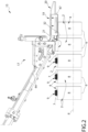
Figure 2 is a lateral view of a cap application device of the capping apparatus of Figure 1, with parts removed for clarity; -
Figure 3 is a perspective view of a detail of the cap application device ofFigure 2 , with parts removed for clarity; -
Figure 4 is a lateral view of a detail of the cap application device ofFigure 2 , with parts removed for clarity; -
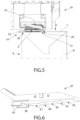
Figure 5 is a front view of the detail ofFigure 4 , with parts removed for clarity; and -
Figure 6 is a perspective view of a further detail of the cap application device ofFigure 2 , with parts removed for clarity. -
Number 1 indicates as a whole a packaging machine for producingpackages 2 filled with a pourable product, in particular a pourable food product, such as (pasteurized) milk, fruit juice, wine, tomato sauce, salt, sugar, emulsions, yoghurt, milk drinks etc. -
Packaging machine 1 may be configured to producepackages 2 filled with the pourable product. - In more detail,
packaging machine 1 may be configured to producepackages 2 from a packaging material having a multilayer configuration. - In further detail, the packaging material may comprise at least one layer of fibrous material, such as e.g. a paper or cardboard, and at least two layers of heat-seal plastic material, e.g. polyethylene, interposing the layer of fibrous material in between one another. One of these two layers of heat-seal plastic material may define the inner face of
package 2 contacting the pourable product. - Moreover, the packaging material may also comprise a layer of gas- and light-barrier material, e.g. aluminum foil or ethylene vinyl alcohol (EVOH) film, in particular being arranged between one of the layers of the heat-seal plastic material and the layer of fibrous material. Preferentially, the packaging material may also comprise a further layer of heat-seal plastic material being interposed between the layer of gas- and light-barrier material and the layer of fibrous material.
- In further detail, the packaging material may be provided in the form of a
web 3. - With particular reference to Figures 1,
2 ,4 and5 , eachpackage 2 may comprise a respectivemain body 4 formed from the multilayer packaging material and anopening device 5 arranged about a pour opening of the respectivemain body 4. - In more detail,
main body 4 may extend along a longitudinal axis A, a first transversal axis B perpendicular to longitudinal axis A and a second transversal axis C perpendicular to first transversal axis B and longitudinal axis A. Preferentially, the size ofpackage 2 along longitudinal axis A may be larger than the size ofpackage 2 along first transversal axis B and second transversal axis C. - Preferentially,
main body 4 may be parallelepiped-shaped. - According to some preferred non-limiting embodiments,
main body 4 may comprise afirst wall 6, preferentially being transversal, more preferentially perpendicular, to longitudinal axis A, from whichmain body 4 may extend along longitudinal axis A. Preferentially,first wall 6 may define a support surface ofpackage 2, preferentiallymain body 4, which may be designed to be put in contact with a support, such as e.g. a shelf, when, in use, being e.g. exposed within a sales point or when being stored. Preferentially, when being arranged on the support the first wall may define a bottom wall. - Preferentially,
main body 4 may also comprise aside wall 7 being (fixedly) connected tofirst wall 6 and extending, along longitudinal axis A, fromfirst wall 6. - Preferentially,
main body 4 may also comprise asecond wall 8 opposite tofirst wall 6 and being (fixedly) connected toside wall 7. - Preferentially,
side wall 7 may be interposed between and integrally connected tofirst wall 6 andsecond wall 8. - Preferentially,
second wall 8 may define a top wall ofpackage 2, e.g. whenpackage 2 is arranged on a support. - According to the shown non-limiting embodiment,
first wall 6 andsecond wall 8 may be parallel with respect to one another. - According to some other possible embodiments not shown,
second wall 8 andfirst wall 6 may be inclined with respect to one another, preferentiallysecond wall 8 may be inclined with respect tofirst wall 6 and/or longitudinal axis A. - According to some preferred non-limiting embodiments,
second wall 8 may carry and/or comprise the designated pour opening and openingdevice 3 may be connected tosecond wall 8. - According to some possible embodiments, each pour opening may be covered by a separation membrane, the separation membrane being preferentially formed from portions of the multilayer packaging material.
- Each
opening device 5 may comprise acollar 9 protruding from the respectivemain body 4, preferentiallysecond wall 8, and being arranged about the respective pour opening. Preferentially, eachcollar 9 may comprise a respective outlet opening configured to allow for the outpouring of the pourable product. - Each
opening device 5 may also comprise acap 10 secured ontocollar 9, and preferentially being configured to selectively open and close the respective pour opening. Preferentially, eachcollar 9 may include an outer projection and eachcap 10 may comprise an inner projection, configured to engage with the outer projection of therespective collar 9. - In particular, each
cap 10 may be controllable between a respective closing position at whichcap 10 closes the outlet opening (for impeding the outflow of the pourable product) and an opening position at whichcap 10 frees the outlet opening (for allowing the outflow of the pourable product). Preferentially, eachcap 10 is secured to therespective package 2 and is in the closing position when being delivered to an end user. - Preferentially, each
cap 10 may be (repeatably) moveable between the respective closing position and the respective opening position. - Moreover, each
cap 10 may comprise a lateral wall, preferentially having an annular shape, and a lid, extending from the respective lateral wall. Preferentially, the lid may be moveable so as to control therespective cap 10 between the respective closing position and the respective opening position. - E.g. the lid may be hinged to the respective lateral wall and may be angularly moveable about a hinge axis so as to set
cap 10 between the respective closing position and the respective opening position. - Preferentially, each lateral wall surrounds a portion of
collar 9 aftercap 10 has been secured onto therespective collar 9. - According to some possible embodiments, each
opening device 5 may also comprise a respective coupling element connected to and protruding from the respective separation membrane. Preferentially, each coupling element may be also connected to, preferentially sealed to, therespective cap 10. In particular, during a first-time control of therespective cap 10 into the respective opening position, the coupling element follows movement of therespective cap 10 leading to a detachment of the respective separation membrane from the respectivemain body 4. - Preferentially, each coupling element may be surrounded by the
respective collar 9. More preferentially, each coupling element may comprise a portion protruding out ofcollar 9. - According to some preferred non-limiting embodiments, each
opening device 5 may also comprise a base frame carrying therespective collar 9 and being connected to, preferentially molded onto or glued to, the respectivemain body 4. - Preferentially, each
collar 9 may be integral to the respective base frame and/or may extend from the respective base frame. - In further detail, each
collar 9 may extend along a respective central axis. - Moreover, each
collar 9 may have an annular shape. Preferentially, eachcollar 9 may have a circular shape. - According to some preferred non-limiting embodiments, each
collar 9 may be molded to the respectivemain body 4, preferentially the respectivesecond wall 8. Preferentially, eachcollar 9 may be molded to web ofpackaging material 3 prior to forming and fillingpackages 2, preferentiallymain body 4. - More specifically, each
collar 9 may be molded onto the respectivemain body 4 together with the respective base frame. Preferentially, eachcollar 9 may be molded onto web ofpackaging material 3 together with the respective base frame prior to forming and fillingpackages 2, preferentiallymain body 4. - Additionally, also each coupling element may be molded to the respective
main body 4, preferentially to web of packaging material prior of forming and fillingpackages 2, preferentiallymain body 4. - With particular reference to Figure 1,
packaging machine 1 may comprise: - a
package filling apparatus 14 configured to form and fillpackages 2, in particular configured to formpackages 2 from the multilayer packaging material and to fillpackages 2 with the pourable product; and - at least one
capping apparatus 15 configured to at least secure onerespective cap 10 to eachcollar 9. - Preferentially, capping
apparatus 15 may be arranged downstream frompackage filling apparatus 14 and may be configured to receive formed and filledpackages 2 frompackage filling apparatus 14. - Please note that for reasons of simplicity, in the present description, when discussing operation of capping
apparatus 15, we do not use different terms to indicatepackages 2 which still need to receive therespective caps 10 and which have therespective caps 10. We consider that such differences are directly understandable from the description. - With particular reference to
Figure 2 , cappingapparatus 15 comprises: - a conveying device configured to advance
packages 2 along and advancement path P, preferentially advancement path P having a linear shape; - a
cap application device 16 configured to apply onerespective cap 10 onto eachcollar 9. - As will be explained further below,
cap application device 16 is configured to applycaps 10 onto therespective collars 9, but after application these are not yet fully secured onto therespective collars 9. - In more detail, in use, after operation of
cap application device 16collar 9, preferentially the respective lateral wall, may be only partially coupled tocollar 9; i.e. the respective lateral wall surrounds already some portions ofcollar 9, but not yet all the portions, which the respective lateral wall should surround. - Therefore, preferentially, capping
apparatus 15 may also comprise one or more cap securing devices configured to securecaps 10 onto therespective collars 9. E.g. each cap securing device may be configured to screw and/or pushcaps 10 onto therespective collars 9. - More preferentially, each cap securing device ensures, in use, that each
cap 10, preferentially the respective lateral wall, may be fully coupled to therespective collar 9. E.g. the respective lateral wall may surround all the portions which the respective lateral wall should surround after having been secured tocollar 9. - Preferentially, the cap securing devices may be arranged downstream from
cap application device 16 along advancement path P. - According to some possible embodiments, capping
apparatus 15 may comprise only one cap securing device. Preferentially, cappingapparatus 15 may comprise more than one cap securing device configured to simultaneously securerespective caps 10 onto therespective collars 9. - According to some possible non-limiting embodiments, capping
apparatus 15 may also comprise one or more cap sealing devices configured to seal the respective coupling elements to therespective caps 10. - Preferentially, the cap sealing devices may be arranged downstream from the cap securing devices along advancement path P.
- According to some possible embodiments, capping
apparatus 15 may comprise only one cap sealing device. Preferentially, cappingapparatus 15 may comprise more than one cap sealing device configured to simultaneously seal the respective coupling elements to therespective caps 10. - With particular reference to
Figures 2 to 5 ,cap application device 16 comprises acap delivery unit 17 configured to deliver caps 10 (in sequence) to a transfer station at which caps 10 are engaged onto therespective collars 9. - In practice, it may occur that the actual shape of
main bodies 4 may differ from an ideal shape, e.g. due to the presence of the pourable product, etc. Therefore, also the exact shape of the respectivesecond walls 7 may present deviations from the ideal shape. E.g.second walls 7 may have a convex shape and/or have bulges. - With particular reference to
Figures 2 to 6 ,cap application device 16 comprises a pressuringunit 19 configured to apply a flattening force F on the respectivesecond walls 7 for flattening the respectivesecond walls 7. In particular, pressuringunit 19 is configured to apply the flattening force F onto eachsecond wall 7 during advancement of therespective package 2 along a portion of advancement path P. Flattening force F may be applied, in use, along a direction perpendicular to the respectivesecond wall 7 and towards the respectivefirst wall 6. - Additionally,
cap application device 16 may comprise aninteraction unit 20 configured to presscap 10 onto therespective collar 9 while, in use, pressuringunit 19 exerts flattening force F on the respectivesecond wall 7. - Preferentially, packages 2 when advancing along advancement path P pass (in sequence) through the transfer station and afterwards interact with pressuring
unit 19. - In particular,
interaction unit 20 may be arranged downstream from the transfer station with respect to advancement path P and configured to exert a force onto eachcap 10 and towards the respectivemain body 4, preferentially the respectivesecond wall 7, so as to further press caps 10 ontocollars 9. - In particular,
interaction unit 19 guarantees that caps 10 are pre-applied ontocollars 9. Afterwards, cap securing device securescaps 10 ontocollars 9. - According to some preferred non-limiting embodiments, pressuring
unit 19 may be arranged downstream from the transfer station along advancement path P. - Advantageously and with particular reference to
Figures 2 to 4 ,cap application device 16 may also comprise analignment unit 21 configured to aligncollars 9 with respect tocaps 7 at the transfer station. Preferentially,alignment unit 21 may be arranged upstream of pressuringunit 19 along advancement path P. - With particular reference to
Figures 2 to 5 , pressuringunit 19 may comprise afirst bar 25 and asecond bar 26 spaced apart from one another, preferentially along a direction D perpendicular to advancement path P and defining anadvancement space 27. In use,collars 9 advance withinadvancement space 27, while pressuringunit 19 exerts flattening force F onto the respectivesecond walls 7. In other words, in use, while advancing along a respective portion of advancement path P,collars 9 are interposed betweenfirst bar 25 andsecond bar 27. - Furthermore,
first bar 25 andsecond bar 26 are configured to exert flattening force F onto the respectivesecond walls 7 by engagingsecond walls 7. - In more detail, each one of
first bar 25 andsecond bar 26 may comprise a respective first end portion and a respective second end portion opposite to first end portion. Preferentially, first end portion may be upstream of the second end portion along advancement path P. - According to some preferred non-limiting embodiments,
first bar 25 may have afirst engagement surface 30 andsecond bar 26 may have asecond engagement surface 31. - Moreover,
first engagement surface 30 andsecond engagement surface 31 are configured to engage the respectivesecond walls 7 so as to exert the flattening force. - In particular,
first bar 25 and second bar 26 (and accordingly,first engagement surface 30 and second engagement surface 31) have respective defined positions. Accordingly, in use, during advancement ofpackages 2 along advancement path P at some point of their advancement eachpackage 2 arrives to interact withfirst bar 25 and second bar 26 (in particular, starting to interact with the respective first end portions 28) . Asfirst bar 25 andsecond bar 26 have their defined positions,second walls 7 are flattened as a result of the force exerted byfirst bar 25 andsecond bar 26. - Preferentially, the desired position of
first bar 25 andsecond bar 26 may be adjustable prior to operation ofcap application device 16, e.g. in dependence of a specific format ofpackages 2. - In further detail,
first engagement surface 30 andsecond engagement surface 31 may each be and/or comprise a respective plane surface. - In particular,
first engagement surface 30 andsecond engagement surface 31 lie within a common plane. - Preferentially, the common plane defines a desired shape of
second walls 7 during operation ofinteraction unit 20. - Preferentially, pressuring
unit 19 may be arranged such that the common plane may be parallel tofirst wall 6 and/or may be perpendicular to longitudinal axis A if second walls 7 (at least when considering the ideal shape) is parallel tofirst wall 6 and/or perpendicular to longitudinal axis A. In particular, the common plane may be parallel, in use, to direction D and advancement path P. - In the case that second walls 7 (at least when considering the ideal shape) may be inclined with respect to
first wall 6 and/or to longitudinal axis A,first bar 25 andsecond bar 26 may be arranged such that also the common plane is inclined with respect tofirst wall 6 and/or to longitudinal axis A. - According to some preferred non-limiting embodiments,
first bar 25 andsecond bar 26 may extend each along a respective longitudinal axis G. - Accordingly,
first engagement surface 30 andsecond engagement surface 31 may extend along the respective longitudinal axis G. - Preferentially,
first bar 25 andsecond bar 26, preferentially the respective longitudinal axes G, are parallel to one another, and preferentially also to advancement path P. - With particular reference to
Figures 2 to 4 ,alignment unit 21 may comprise afirst guide 32 and a second guide spaced apart from one another, configured to engagecollars 9 from opposite sides thereof and to aligncollars 9 with respect to therespective caps 10. - Preferentially,
first bar 25 andsecond bar 26 may be parallel to, respectively,first guide 32 and the second guide. - Moreover,
first bar 25 andsecond bar 26 may be arranged downstream from, respectively,first guide 32 andsecond guide 32. - In particular, while
alignment unit 21 allows that caps 10 are correctly placed on therespective collars 9, pressuringunit 19 allows that caps 10 are correctly pressed onto therespective collars 9. - Furthermore, the scope of
alignment unit 21 is such that during the transfer ofcaps 10 ontocollars 9,collars 9 are correctly aligned with respect to therespective caps 10 and such that therespective caps 10 are correctly applied onto therespective collars 9. In particular,alignment unit 21 may be configured to guarantee a desired relative position of eachcollar 9 at the transfer station. - With particular reference to 2, 4 and 6,
interaction unit 20 may comprise a pressuringsurface 37 configured to interact withcaps 10 during advancement ofpackages 2 along a respective portion of advancement path P and to exert a pressuring force ontocaps 10 and into a pressuring direction, preferentially being (substantially) parallel to flattening force F and towards the respectivesecond walls 7. - In particular, pressuring
surface 37 allows to partially press caps 10 onto therespective collars 9. - Preferentially, pressuring
surface 37 may be configured to presscaps 10 onto therespective collars 10 during exertion of flattening force F onto the respectivesecond walls 7 by means of pressuringunit 19. In particular, along advancement path P, pressurizingsurface 37 is superposed with a portion offirst engagement surface 30 andsecond engagement surface 31 of pressuringunit 19. - In further detail,
interaction unit 20 may also comprise afirst transition surface 38 arranged upstream of pressuringsurface 37 along advancement path P and configured to interact withcaps 10, in particular prior to pressuringsurface 37 interacting withcaps 10 during advancement ofpackages 2 along advancement path P. - Moreover,
first transition surface 38 may be connected to and may be inclined with respect to pressuringsurface 37. - In particular,
first transition surface 38 may guarantee to a smooth interaction ofinteraction unit 20 withcaps 10. - More specifically,
first transition surface 38 may comprise an initial portion and a terminal portion opposite to the initial portion. The terminal portion is connected to pressuringsurface 37. - Additionally,
first transition surface 38 may be arranged such that, in use, the terminal portion is, in use, closer to the respectivesecond walls 7 and/orcollars 9 than the initial portion. In other words,first transition surface 38 may be inclined such that the initial portion may be on a higher height level than the terminal portion. - In particular, also pressuring
surface 37 may be closer to therespective collars 10 and/orsecond walls 7 than the initial portion. - According to some preferred non-limiting embodiments, pressuring
surface 37 may be planar. - According to some preferred non-limiting embodiments,
interaction unit 20 may also comprise a retainingsurface 39 arranged downstream from pressuringsurface 37 along advancement path P and being arranged such to be, in use, more distanced fromcollars 9 and/orsecond walls 7 than pressuringsurface 37. Retainingsurface 39 is configured to interact withcaps 10. In particular, once pressuringsurface 37 has pressed eachcap 10 onto therespective collar 10, the force acting on eachcap 10 shall be gradually decreased. - In particular, retaining
surface 39 is on a higher height level than pressuringsurface 37. Preferentially, along advancement path P, a portion of retainingsurface 39 is superposed with a portion offirst engagement surface 30 andsecond engagement surface 31 of pressuringunit 19. Also, preferentially, along advancement path P, another portion of retainingsurface 39 is arranged downstream offirst engagement surface 30 andsecond engagement surface 31 of pressuringunit 19. - Additionally,
interaction unit 20 may also comprise asecond transition surface 40 extending from pressuringsurface 37 to retainingsurface 39. In particular,second transition surface 40 may be inclined with respect to both pressuringsurface 37 and retainingsurface 39. - Preferentially, retaining
surface 39 may have a planar shape. -
Second transition surface 40 may allow a gradual movement ofcollar 9 and cap 10 applied ontocollar 9 from a first relative position as defined by pressuringsurface 37 to a second relative position as defined by retainingsurface 39. In particular, along advancement path P,second transition surface 40 is superposed with a portion offirst engagement surface 30 andsecond engagement surface 31 of pressuringunit 19. - In further detail,
interaction unit 20 may also comprise anauxiliary retaining surface 41 arranged downstream from retainingsurface 39 along advancement path P and being arranged such to be, in use, more distanced fromcollars 9 and/orsecond walls 7 than retainingsurface 39. - In other words, retaining
surface 39 may be on a lower height level than auxiliary retainingsurface 41. - Additionally, auxiliary retaining
surface 41 may be configured to interact withcaps 10. - According to some preferred non-limiting embodiments, auxiliary retaining
surface 41 may have a planar shape. - Advantageously, auxiliary retaining
surface 41 may also be arranged downstream from pressuring unit 19 (in particular,engagement surface 30 and second engagement surface 31) along advancement path P. Thus, auxiliary retainingsurface 41 may interact withcaps 10 while no flattening force F interacts on the respectivesecond walls 7. - Additionally,
interaction unit 20 may also comprise athird transition surface 42 extending from retainingsurface 39 toauxiliary retaining surface 41. - In particular,
third transition surface 42 may be inclined with respect to both retainingsurface 39 andauxiliary retaining surface 41. - By having retaining
surface 39 and/orauxiliary retaining surface 41 one further reduces the possible occurrence of bouncing effects ofcaps 10. In fact,cap 10 is released from theinteraction unit 20 in a gradual manner, i.e. in steps. - Moreover,
second transition surface 40 andthird transition surface 42 may allow a smooth handling ofcaps 10. - With particular reference to
Figures 4 and6 ,cap delivery unit 17 may comprise a pair of delimitingwalls 43 configured to laterally engagecaps 10 from opposite sides thereof at the transfer station and during transfer (application) ofcaps 10 onto therespective collars 9. In particular, delimitingwalls 43 allow to stabilizecaps 10 during transfer ontocollars 9. - In particular, delimiting
walls 43 may be arranged abovealignment unit 21. - Preferentially, delimiting
walls 43 may be parallel to advancement path P. - Preferentially, delimiting
walls 43 may be arranged at the transfer station. - According to some preferred non-limiting embodiments,
cap delivery unit 17 may also comprise adelivery channel 44 configured to contain a plurality ofcaps 10 and to directcap 10 to the transfer station. Preferentially, delimitingwalls 43 may delimitdelivery channel 44 and/or extend fromdelivery channel 44 downwards, at least at the transfer station. - Additionally,
cap delivery unit 17 may also comprise a retaining mechanism controllable between an active configuration at which the retaining mechanism is configured to retain onecap 10 at a time at the transfer station and a release configuration at which the retaining mechanism is configured to releasecap 10 onto onerespective collar 9 at the transfer station. - According to some possible embodiments,
cap delivery unit 17 may be configured such that while the retaining mechanism retainscap 10 at the transfer station, cap 10 is inclined with respect to therespective receiving collar 9. Moreover, only during release,cap 10 may change its orientation such that during application ofcap 10 ontocollar 9,cap 10 may be coaxial tocollar 9. - With particular reference to Figure 1,
package filling apparatus 14 may be configured to producepackages 2 and to fillpackages 2 with the pourable product. - In more detail,
package filling apparatus 14 may be configured to producepackages 2 by forming atube 50 fromweb 3, longitudinally sealingtube 50, fillingtube 50 with the pourable product and to transversally seal and cuttube 50. - In use,
packaging machine 1 producespackages 2 filled with the pourable product. - Operation of
packaging machine 1 comprises at least the steps of: - forming and filling
packages 2 with the pourable product, in particular executed by ofpackage filling apparatus 14; and - securing caps 10 on
collars 9, in particular executed by cappingapparatus 15. - Even more particular, during the step of forming and filling,
tube 50 is formed from advancingweb 3, is longitudinally sealed, filled with the pourable product and transversally sealed and cut. - According to some preferred embodiments, operation of
packaging machine 1 may also comprise a step of feeding, during which packages 2 are fed, in particular frompackage filling apparatus 7, to cappingapparatus 15. - In more detail, during the step of securing, the following sub-steps are executed:
- applying
caps 10 ontocollars 9 by means ofcap application device 16; - preferentially, securing
caps 10 oncollars 9 by means of a cap securing device; and - preferentially, sealing the connection elements to
caps 10. - During the sub-step of applying, pressuring
unit 19 exerts flattening force F on the respectivesecond walls 7. - The advantages of
cap application device 16 and/or cappingapparatus 15 and/or ofpackaging machine 1 according to the present invention will be clear from the foregoing description. - In particular, pressuring
unit 19 ensures a correct pre-application ofcaps 10 ontocollars 9. In fact, pressuringunit 19 ensures thatwall 7 ofpackage 2 is planar during pre-application ofcaps 10; planarity ofwall 7 ensures thatcollar 9 is arranged in a desired position and according to a desired orientation when receivingcap 10. As a result,cap 10 is correctly applied. - Additionally,
interaction unit 20 avoids undesired bouncing effects ofcaps 10 when package with cap is released from cap application device. - Clearly, changes may be made to cap
application device 16 and/or cappingapparatus 15 and/orpackaging machine 1 as described herein without, however, departing from the scope of protection as defined in the accompanying claims.
Claims (15)
- Cap application device (16) for a capping apparatus (15) for applying caps (10) onto collars (9) of packages (2) advancing along an advancement path (P); wherein the collars (9) extend from respective walls (7) of the respective packages (2);
the cap application device (16) comprises:- a cap delivery unit (17) configured to deliver the caps (10) to a transfer station at which the caps (10) are engaged onto the respective collars (9);- a pressuring unit (19) configured to apply a flattening force (F) on the respective walls (7) carrying the respective collars (9) for flattening the respective walls (7) and during advancement of the respective packages (2) along a portion of the advancement path (P); and- an interaction unit (20) configured to press the caps (10) onto the respective collars (9) while, in use, the pressuring unit (19) exerts the flattening force (F) on the respective walls (7). - Cap application device (16) according to claim 1, wherein the pressuring unit (19) comprises a first bar (25) and a second bar (26) spaced apart from one another and defining an advancement space (27); wherein, in use, the collars (9) advance within the advancement space (27);
wherein the first bar (25) and the second bar (26) are configured to engage the respective walls (7) and to exert the flattening force (F) onto the respective walls (7). - Cap application device (16) according to claim 2, wherein the first bar (25) has a first engagement surface (30) and the second bar (26) has a second engagement surface (31) ;wherein the first engagement surface (30) and the second engagement surface (31) are configured to engage the respective walls (7) so as to exert the flattening force (F).wherein the first engagement surface (30) and the second engagement surface (31) comprise or are plane surfaces.
- Cap application device (16) according to claim 2 or 3, wherein the first bar (25) and the second bar (26) are spaced apart from one another along a direction (D) perpendicular to the advancement path (P) of the packages (2); and
wherein the first bar (25) and the second bar (26) extend each along a respective longitudinal axis (G) parallel to said direction (D). - Cap application device (16) according to any one of the preceding claims, comprising an alignment unit (21) configured to align the collars (9) of the packages (2) with respect to the caps (10) at the transfer station;
wherein the alignment unit (21) is arranged upstream of the pressuring unit (19) along the advancement path (P). - Cap application device (16) according to claim 5 and when depending on any one of claims 2 to 4, wherein the alignment unit (21) comprises a first guide (32) and a second guide spaced apart from one another, configured to engage the collars (9) from opposite sides thereof and to align the collars (9) with respect to the caps (10);wherein the first bar (25) is parallel to the first guide (30) and the second bar (26) is parallel to the second guide (31);wherein the first bar (25) and the second bar (26) are arranged downstream from, respectively, the first guide (30) and the second guide (32).
- Cap application device (16) according to any one of the preceding claims, wherein the interaction unit (20) comprises a pressuring surface (37) configured to interact with the caps (10) during advancement of the packages (2) along a respective portion of the advancement path (P) and to exert a pressuring force onto the caps (10) and into a pressuring direction;
wherein the pressuring surface (37) is arranged such to exert the pressuring force while, in use, the pressuring unit (19) exerts the flattening force (F) onto the respective walls (7). - Cap application device (16) according to claim 7, wherein the interaction unit (20) comprises a first transition surface (38) arranged upstream of the pressuring surface (37) along the advancement path (P) and configured to interact with the caps (10);wherein the first transition surface (38) is connected to and inclined with respect to the pressuring surface (37);wherein the first transition surface (38) comprises an initial portion and a terminal portion opposite to the initial portion;wherein the terminal portion is connected to the pressuring surface (37);wherein the first transition surface (38) is arranged such that, in use, the terminal portion is, in use, closer to the respective collars (7) and/or the respective walls (7) than the initial portion.
- Cap application device (16) according to claim 7 or 8, wherein the interaction unit (20) also comprises a retaining surface (39) arranged downstream from the pressuring surface (37) along the advancement path (P) and being arranged such to be, in use, more distanced from the respective collars (9) and/or the respective walls (7) than the pressuring surface (37);
wherein the retaining surface (39) is configured to interact with the caps (10). - Cap application device (16) according to claim 9, wherein the interaction unit (20) also comprises a second transition surface (40) extending from the pressuring surface (37) to the retaining surface (39).
- Cap application device (16) according to claim 9 or 10, wherein the interaction unit (20) also comprises an auxiliary retaining surface (41) arranged downstream from the retaining surface (39) along the advancement path (P) and being arranged such to be, in use, more distanced from the collars (9) and/or the walls (7) than the retaining surface (39);
wherein the auxiliary retaining surface (41) is configured to interact with the caps (10). - Cap application device (16) according to claim 11, wherein the interaction unit (20) also comprises a third transition surface (42) extending from the retaining surface (39) to the auxiliary retaining surface (41); and/or
the auxiliary retaining surface (41) is arranged downstream from the pressuring unit (19) along the advancement path (P). - Capping apparatus (15) for securing caps (10) onto collars (9) of packages (2) produced in a packaging machine (1) comprising:- a conveying device configured to advance the respective packages (2) along an advancement path (P);- a cap application device (16) according to any one of the preceding claims configured to apply caps (10) onto the collars (9) of the packages (2).
- Capping apparatus according to claim 13 further comprising at least one securing device arranged downstream from the cap application device (16) along the advancement path (P) and configured to secure the caps (10) on the collars (9).
- Packaging machine (1) for producing packages (2) having collars (9) and being filled with a pourable product comprising:- a package filling apparatus (14) for forming and filling the packages (2) with the pourable product; and- at least one capping apparatus (15) according to claim 14.
Applications Claiming Priority (1)
| Application Number | Priority Date | Filing Date | Title |
|---|---|---|---|
| IT102023000014826A IT202300014826A1 (en) | 2023-07-14 | 2023-07-14 | CAP APPLICATION DEVICE, CAPPER APPARATUS FOR A PACKAGING MACHINE AND PACKAGING MACHINE HAVING A CAPPER APPARATUS |
Publications (2)
| Publication Number | Publication Date |
|---|---|
| EP4491524A1 true EP4491524A1 (en) | 2025-01-15 |
| EP4491524B1 EP4491524B1 (en) | 2025-12-24 |
Family
ID=88098458
Family Applications (1)
| Application Number | Title | Priority Date | Filing Date |
|---|---|---|---|
| EP24184150.1A Active EP4491524B1 (en) | 2023-07-14 | 2024-06-25 | Cap application device for a capping apparatus, capping apparatus for a packaging machine and packaging machine having a capping apparatus |
Country Status (6)
| Country | Link |
|---|---|
| EP (1) | EP4491524B1 (en) |
| JP (1) | JP2026523707A (en) |
| CN (1) | CN121487872A (en) |
| IT (1) | IT202300014826A1 (en) |
| MX (1) | MX2025014201A (en) |
| WO (1) | WO2025016674A1 (en) |
Citations (8)
| Publication number | Priority date | Publication date | Assignee | Title |
|---|---|---|---|---|
| US5304265A (en) * | 1990-08-24 | 1994-04-19 | International Paper Company | In-line fitment sealing apparatus and method |
| US20030159408A1 (en) * | 2001-08-08 | 2003-08-28 | Seebeger Robert B. | Nitrogen cap chute end |
| US20060213151A1 (en) * | 2003-08-08 | 2006-09-28 | Sig Technology Ltd. | Device and method for fixing closing films to pouring elements arranged on composite packages |
| US20070006550A1 (en) * | 2005-07-08 | 2007-01-11 | Sig Technology Ag | Method and Machine for Closing Bottles with Sterile Caps |
| US20130318920A1 (en) * | 2012-06-05 | 2013-12-05 | Kenneth J. Herzog | Cap stabilizer for capping device |
| EP3153414A1 (en) | 2015-10-05 | 2017-04-12 | Tetra Laval Holdings & Finance S.A. | An applying unit for applying a lid onto a container |
| EP3205589A1 (en) | 2016-02-12 | 2017-08-16 | Tetra Laval Holdings & Finance S.A. | A distribution unit for feeding lids to necks of containers |
| WO2019229561A1 (en) * | 2018-05-30 | 2019-12-05 | Guala Pack S.P.A. | Ultra-clean or aseptic chamber pouch filling machine |
-
2023
- 2023-07-14 IT IT102023000014826A patent/IT202300014826A1/en unknown
-
2024
- 2024-06-25 WO PCT/EP2024/067715 patent/WO2025016674A1/en not_active Ceased
- 2024-06-25 JP JP2026500173A patent/JP2026523707A/en active Pending
- 2024-06-25 CN CN202480046635.7A patent/CN121487872A/en active Pending
- 2024-06-25 EP EP24184150.1A patent/EP4491524B1/en active Active
-
2025
- 2025-11-27 MX MX2025014201A patent/MX2025014201A/en unknown
Patent Citations (8)
| Publication number | Priority date | Publication date | Assignee | Title |
|---|---|---|---|---|
| US5304265A (en) * | 1990-08-24 | 1994-04-19 | International Paper Company | In-line fitment sealing apparatus and method |
| US20030159408A1 (en) * | 2001-08-08 | 2003-08-28 | Seebeger Robert B. | Nitrogen cap chute end |
| US20060213151A1 (en) * | 2003-08-08 | 2006-09-28 | Sig Technology Ltd. | Device and method for fixing closing films to pouring elements arranged on composite packages |
| US20070006550A1 (en) * | 2005-07-08 | 2007-01-11 | Sig Technology Ag | Method and Machine for Closing Bottles with Sterile Caps |
| US20130318920A1 (en) * | 2012-06-05 | 2013-12-05 | Kenneth J. Herzog | Cap stabilizer for capping device |
| EP3153414A1 (en) | 2015-10-05 | 2017-04-12 | Tetra Laval Holdings & Finance S.A. | An applying unit for applying a lid onto a container |
| EP3205589A1 (en) | 2016-02-12 | 2017-08-16 | Tetra Laval Holdings & Finance S.A. | A distribution unit for feeding lids to necks of containers |
| WO2019229561A1 (en) * | 2018-05-30 | 2019-12-05 | Guala Pack S.P.A. | Ultra-clean or aseptic chamber pouch filling machine |
Also Published As
| Publication number | Publication date |
|---|---|
| WO2025016674A1 (en) | 2025-01-23 |
| JP2026523707A (en) | 2026-07-14 |
| IT202300014826A1 (en) | 2025-01-14 |
| MX2025014201A (en) | 2026-01-07 |
| EP4491524B1 (en) | 2025-12-24 |
| CN121487872A (en) | 2026-02-06 |
Similar Documents
| Publication | Publication Date | Title |
|---|---|---|
| CN107922060B (en) | An application unit for applying a lid to a container | |
| CN107922062B (en) | Method and applicator head for applying caps to containers | |
| US20250304316A1 (en) | Spout for a container and package-spout assembly | |
| EP1726526B1 (en) | Folding unit for pourable food product packaging machines | |
| DK3153415T3 (en) | DEVICE TO CLOSE A CONTAINER | |
| CN108290655B (en) | Dispensing unit for feeding caps to the neck of a container | |
| EP4357253A1 (en) | Folding apparatus and packaging machine having a folding apparatus | |
| CN107921715B (en) | Welding head | |
| JP2024535253A (en) | Opening device for a package, mold for molding the opening device for a package, and package having the opening device | |
| EP4357255A1 (en) | Folding apparatus and packaging machine having a folding apparatus | |
| EP4159402B1 (en) | Opening device for a package, mold for molding an opening device for a package and package having an opening device | |
| EP4491524B1 (en) | Cap application device for a capping apparatus, capping apparatus for a packaging machine and packaging machine having a capping apparatus | |
| JP2024535243A (en) | Opening device for a package, mold for molding the opening device for a package, and package having the opening device | |
| EP4464607B1 (en) | Cap application device for a capping apparatus, capping apparatus for a packaging machine and packaging machine having a capping apparatus | |
| CN109070484B (en) | Assembly for producing sealed packaging units | |
| WO2023198615A1 (en) | Infeed conveyor for a folding apparatus, folding apparatus having an infeed conveyor and packaging machine having a folding apparatus | |
| EP4455025A1 (en) | Capping apparatus for a packaging machine and packaging machine having a capping apparatus | |
| EP4357254A1 (en) | Folding apparatus and packaging machine having a folding apparatus | |
| US20250153892A1 (en) | Lid assembly for a package, lid-spout group for a package and package having a lid-spout group | |
| EP3318500A1 (en) | Applying apparatus and method for applying opening devices to packages |
Legal Events
| Date | Code | Title | Description |
|---|---|---|---|
| PUAI | Public reference made under article 153(3) epc to a published international application that has entered the european phase |
Free format text: ORIGINAL CODE: 0009012 |
|
| STAA | Information on the status of an ep patent application or granted ep patent |
Free format text: STATUS: THE APPLICATION HAS BEEN PUBLISHED |
|
| AK | Designated contracting states |
Kind code of ref document: A1 Designated state(s): AL AT BE BG CH CY CZ DE DK EE ES FI FR GB GR HR HU IE IS IT LI LT LU LV MC ME MK MT NL NO PL PT RO RS SE SI SK SM TR |
|
| STAA | Information on the status of an ep patent application or granted ep patent |
Free format text: STATUS: REQUEST FOR EXAMINATION WAS MADE |
|
| 17P | Request for examination filed |
Effective date: 20250715 |
|
| GRAP | Despatch of communication of intention to grant a patent |
Free format text: ORIGINAL CODE: EPIDOSNIGR1 |
|
| STAA | Information on the status of an ep patent application or granted ep patent |
Free format text: STATUS: GRANT OF PATENT IS INTENDED |
|
| GRAS | Grant fee paid |
Free format text: ORIGINAL CODE: EPIDOSNIGR3 |
|
| GRAA | (expected) grant |
Free format text: ORIGINAL CODE: 0009210 |
|
| STAA | Information on the status of an ep patent application or granted ep patent |
Free format text: STATUS: THE PATENT HAS BEEN GRANTED |
|
| INTG | Intention to grant announced |
Effective date: 20251029 |
|
| AK | Designated contracting states |
Kind code of ref document: B1 Designated state(s): AL AT BE BG CH CY CZ DE DK EE ES FI FR GB GR HR HU IE IS IT LI LT LU LV MC ME MK MT NL NO PL PT RO RS SE SI SK SM TR |
|
| REG | Reference to a national code |
Ref country code: CH Ref legal event code: F10 Free format text: ST27 STATUS EVENT CODE: U-0-0-F10-F00 (AS PROVIDED BY THE NATIONAL OFFICE) Effective date: 20251224 Ref country code: GB Ref legal event code: FG4D |
|
| REG | Reference to a national code |
Ref country code: DE Ref legal event code: R096 Ref document number: 602024001814 Country of ref document: DE |
|
| REG | Reference to a national code |
Ref country code: LT Ref legal event code: MG9D |
|
| PG25 | Lapsed in a contracting state [announced via postgrant information from national office to epo] |
Ref country code: NO Free format text: LAPSE BECAUSE OF FAILURE TO SUBMIT A TRANSLATION OF THE DESCRIPTION OR TO PAY THE FEE WITHIN THE PRESCRIBED TIME-LIMIT Effective date: 20260324 |
|
| PG25 | Lapsed in a contracting state [announced via postgrant information from national office to epo] |
Ref country code: HR Free format text: LAPSE BECAUSE OF FAILURE TO SUBMIT A TRANSLATION OF THE DESCRIPTION OR TO PAY THE FEE WITHIN THE PRESCRIBED TIME-LIMIT Effective date: 20251224 Ref country code: FI Free format text: LAPSE BECAUSE OF FAILURE TO SUBMIT A TRANSLATION OF THE DESCRIPTION OR TO PAY THE FEE WITHIN THE PRESCRIBED TIME-LIMIT Effective date: 20251224 |
|
| PG25 | Lapsed in a contracting state [announced via postgrant information from national office to epo] |
Ref country code: RS Free format text: LAPSE BECAUSE OF FAILURE TO SUBMIT A TRANSLATION OF THE DESCRIPTION OR TO PAY THE FEE WITHIN THE PRESCRIBED TIME-LIMIT Effective date: 20260324 |
|
| PG25 | Lapsed in a contracting state [announced via postgrant information from national office to epo] |
Ref country code: LV Free format text: LAPSE BECAUSE OF FAILURE TO SUBMIT A TRANSLATION OF THE DESCRIPTION OR TO PAY THE FEE WITHIN THE PRESCRIBED TIME-LIMIT Effective date: 20251224 |
|
| REG | Reference to a national code |
Ref country code: NL Ref legal event code: MP Effective date: 20251224 |
|
| PG25 | Lapsed in a contracting state [announced via postgrant information from national office to epo] |
Ref country code: BG Free format text: LAPSE BECAUSE OF FAILURE TO SUBMIT A TRANSLATION OF THE DESCRIPTION OR TO PAY THE FEE WITHIN THE PRESCRIBED TIME-LIMIT Effective date: 20251224 |
|
| REG | Reference to a national code |
Ref country code: AT Ref legal event code: MK05 Ref document number: 1870589 Country of ref document: AT Kind code of ref document: T Effective date: 20251224 |
|
| PG25 | Lapsed in a contracting state [announced via postgrant information from national office to epo] |
Ref country code: NL Free format text: LAPSE BECAUSE OF FAILURE TO SUBMIT A TRANSLATION OF THE DESCRIPTION OR TO PAY THE FEE WITHIN THE PRESCRIBED TIME-LIMIT Effective date: 20251224 |
|
| PG25 | Lapsed in a contracting state [announced via postgrant information from national office to epo] |
Ref country code: LT Free format text: LAPSE BECAUSE OF FAILURE TO SUBMIT A TRANSLATION OF THE DESCRIPTION OR TO PAY THE FEE WITHIN THE PRESCRIBED TIME-LIMIT Effective date: 20251224 |
|
| PG25 | Lapsed in a contracting state [announced via postgrant information from national office to epo] |
Ref country code: SM Free format text: LAPSE BECAUSE OF FAILURE TO SUBMIT A TRANSLATION OF THE DESCRIPTION OR TO PAY THE FEE WITHIN THE PRESCRIBED TIME-LIMIT Effective date: 20251224 |
|
| PG25 | Lapsed in a contracting state [announced via postgrant information from national office to epo] |
Ref country code: ES Free format text: LAPSE BECAUSE OF FAILURE TO SUBMIT A TRANSLATION OF THE DESCRIPTION OR TO PAY THE FEE WITHIN THE PRESCRIBED TIME-LIMIT Effective date: 20251224 |
|
| PG25 | Lapsed in a contracting state [announced via postgrant information from national office to epo] |
Ref country code: PL Free format text: LAPSE BECAUSE OF FAILURE TO SUBMIT A TRANSLATION OF THE DESCRIPTION OR TO PAY THE FEE WITHIN THE PRESCRIBED TIME-LIMIT Effective date: 20251224 |
|
| PGFP | Annual fee paid to national office [announced via postgrant information from national office to epo] |
Ref country code: DE Payment date: 20260623 Year of fee payment: 3 |
|
| PG25 | Lapsed in a contracting state [announced via postgrant information from national office to epo] |
Ref country code: AT Free format text: LAPSE BECAUSE OF FAILURE TO SUBMIT A TRANSLATION OF THE DESCRIPTION OR TO PAY THE FEE WITHIN THE PRESCRIBED TIME-LIMIT Effective date: 20251224 |
|
| PG25 | Lapsed in a contracting state [announced via postgrant information from national office to epo] |
Ref country code: EE Free format text: LAPSE BECAUSE OF FAILURE TO SUBMIT A TRANSLATION OF THE DESCRIPTION OR TO PAY THE FEE WITHIN THE PRESCRIBED TIME-LIMIT Effective date: 20251224 |
|
| PG25 | Lapsed in a contracting state [announced via postgrant information from national office to epo] |
Ref country code: PT Free format text: LAPSE BECAUSE OF FAILURE TO SUBMIT A TRANSLATION OF THE DESCRIPTION OR TO PAY THE FEE WITHIN THE PRESCRIBED TIME-LIMIT Effective date: 20260424 Ref country code: IS Free format text: LAPSE BECAUSE OF FAILURE TO SUBMIT A TRANSLATION OF THE DESCRIPTION OR TO PAY THE FEE WITHIN THE PRESCRIBED TIME-LIMIT Effective date: 20260424 |
|
| PG25 | Lapsed in a contracting state [announced via postgrant information from national office to epo] |
Ref country code: CZ Free format text: LAPSE BECAUSE OF FAILURE TO SUBMIT A TRANSLATION OF THE DESCRIPTION OR TO PAY THE FEE WITHIN THE PRESCRIBED TIME-LIMIT Effective date: 20251224 |
|
| PG25 | Lapsed in a contracting state [announced via postgrant information from national office to epo] |
Ref country code: SK Free format text: LAPSE BECAUSE OF FAILURE TO SUBMIT A TRANSLATION OF THE DESCRIPTION OR TO PAY THE FEE WITHIN THE PRESCRIBED TIME-LIMIT Effective date: 20251224 |
|
| PG25 | Lapsed in a contracting state [announced via postgrant information from national office to epo] |
Ref country code: SE Free format text: LAPSE BECAUSE OF FAILURE TO SUBMIT A TRANSLATION OF THE DESCRIPTION OR TO PAY THE FEE WITHIN THE PRESCRIBED TIME-LIMIT Effective date: 20251224 |