EP4491515A1 - Passenger suite access for persons with reduced mobility - Google Patents
Passenger suite access for persons with reduced mobility Download PDFInfo
- Publication number
- EP4491515A1 EP4491515A1 EP24183560.2A EP24183560A EP4491515A1 EP 4491515 A1 EP4491515 A1 EP 4491515A1 EP 24183560 A EP24183560 A EP 24183560A EP 4491515 A1 EP4491515 A1 EP 4491515A1
- Authority
- EP
- European Patent Office
- Prior art keywords
- subassembly
- motion
- passenger seat
- assembly
- seat
- Prior art date
- Legal status (The legal status is an assumption and is not a legal conclusion. Google has not performed a legal analysis and makes no representation as to the accuracy of the status listed.)
- Pending
Links
Images




Classifications
-
- B—PERFORMING OPERATIONS; TRANSPORTING
- B64—AIRCRAFT; AVIATION; COSMONAUTICS
- B64D—EQUIPMENT FOR FITTING IN OR TO AIRCRAFT; FLIGHT SUITS; PARACHUTES; ARRANGEMENT OR MOUNTING OF POWER PLANTS OR PROPULSION TRANSMISSIONS IN AIRCRAFT
- B64D11/00—Passenger or crew accommodation; Flight-deck installations not otherwise provided for
- B64D11/06—Arrangements of seats, or adaptations or details specially adapted for aircraft seats
- B64D11/0648—Lower frame constructions
-
- B—PERFORMING OPERATIONS; TRANSPORTING
- B60—VEHICLES IN GENERAL
- B60N—SEATS SPECIALLY ADAPTED FOR VEHICLES; VEHICLE PASSENGER ACCOMMODATION NOT OTHERWISE PROVIDED FOR
- B60N2/00—Seats specially adapted for vehicles; Arrangement or mounting of seats in vehicles
- B60N2/02—Seats specially adapted for vehicles; Arrangement or mounting of seats in vehicles the seat or part thereof being movable, e.g. adjustable
- B60N2/04—Seats specially adapted for vehicles; Arrangement or mounting of seats in vehicles the seat or part thereof being movable, e.g. adjustable the whole seat being movable
- B60N2/14—Seats specially adapted for vehicles; Arrangement or mounting of seats in vehicles the seat or part thereof being movable, e.g. adjustable the whole seat being movable rotatable, e.g. to permit easy access
-
- B—PERFORMING OPERATIONS; TRANSPORTING
- B64—AIRCRAFT; AVIATION; COSMONAUTICS
- B64D—EQUIPMENT FOR FITTING IN OR TO AIRCRAFT; FLIGHT SUITS; PARACHUTES; ARRANGEMENT OR MOUNTING OF POWER PLANTS OR PROPULSION TRANSMISSIONS IN AIRCRAFT
- B64D11/00—Passenger or crew accommodation; Flight-deck installations not otherwise provided for
- B64D11/06—Arrangements of seats, or adaptations or details specially adapted for aircraft seats
- B64D11/0606—Arrangements of seats, or adaptations or details specially adapted for aircraft seats with privacy shells, screens, separators or the like
Definitions
- the present disclosure relates generally to travel accommodations for persons with reduced mobility (PRM), and more particularly, to a motion assembly for a passenger seat configured to move the passenger seat in at least two directions to facilitate seating a PRM.
- the motion assembly operates to move a passenger seat from a first location within a passenger suite to a second location within the suite entrance to facilitate passenger transfer at the aisle.
- PRM Persons with reduced mobility
- transfer wheelchairs may be used to navigate narrow aisles when boarding and deplaning a PRM.
- Seats for accommodating a PRM are typically located at the end of a seat row adjacent to an aisle for convenient transfer.
- the seat armrest may be configured to lower to seat bottom level to facilitate lateral transfer from the wheelchair to the passenger seat.
- Some airliners may be equipped with premium class cabins including individual passenger suites.
- passenger suites may include a suite entrance positioned apart from and at an angle to a passenger seat within the suite.
- the passenger seat may be positioned along one suite wall and oriented in one direction, while the suite entrance may be provided through a different wall and opening in a different direction.
- Such a suite configuration does not allow for direct transfer from a wheelchair to the passenger seat considering the distance and angle of the passenger seat relative to the suite entrance.
- crew assistance is needed to physically lift and move the passenger from the transfer wheelchair to the passenger seat within the suite, which is disruptive to the PRM and invites injury to both the PRM and cabin crew.
- embodiments of the inventive concepts disclosed herein are directed to a motion assembly for a passenger seat.
- the motion assembly includes a first subassembly for linear motion in a first direction, a second subassembly for linear motion in a second direction, and a third subassembly for rotational motion, the third subassembly positioned between and interconnecting the first and second subassemblies, wherein an amount of rotational motion of the third subassembly determines an angle of the second direction relative to the first direction.
- the first subassembly includes a platform translatably mounted to spaced beams
- the third subassembly includes a swivel plate mounted to the platform and a swivel ring rotatably mounted to the swivel plate
- the second subassembly includes a platform mounted to the swivel ring and spaced beams translatably mounted to the platform.
- the spaced beams of the first subassembly are components of a first frame assembly attachable to seat tracks, and the spaced beams of the second subassembly are components of a second frame assembly attachable to the passenger seat.
- the swivel ring is configured to rotate within the swivel plate, the swivel ring has a radially extending feature, the swivel plate has an annular track of a predetermined length determinative of an amount of rotation of the swivel ring relative to the swivel plate, and the radially extending feature is configured, as the swivel ring rotates relative to the swivel plate, to travel within the annular track.
- the third subassembly is configured for up to 90-degrees of rotation such that the second direction is orthogonal to the first direction.
- the motion assembly is configured for sequential operation in that the first subassembly is configured to operate first to provide linear motion in the first direction, the third subassembly is configured to operate second to provide rotational motion, and the second assembly is configured to operate third to provide linear motion in the second direction.
- the third subassembly is configured to operate after linear motion of the first subassembly ceases, and the second subassembly is configured to operate after rotational motion of the third subassembly ceases.
- the inventive concepts disclosed herein are directed to a passenger seat assembly.
- the passenger seat assembly includes a passenger seat, seat tracks, and a motion assembly coupled between the passenger seat and the seat tracks.
- the motion assembly includes a first subassembly for linear motion in a first direction, the first subassembly coupled to the seat tracks, a second subassembly for linear motion in a second direction, the second subassembly coupled to the passenger seat, and a third subassembly for rotational motion, the third subassembly positioned between and interconnecting the first and second subassemblies, wherein an amount of rotational motion of the third subassembly determines an angle of the second direction relative to the first direction.
- the inventive concepts disclosed herein are directed to a passenger suite.
- the passenger suite includes upstanding walls defining an interior space, an entrance provided through one of the upstanding walls, and a passenger seat positioned within the interior space.
- the passenger seat includes a motion assembly configured to move the passenger seat from a first position within the interior space to a second position within the entrance, wherein movement from the first position to the second position includes at least one direction change.
- the motion assembly includes a first subassembly for linear motion in a first direction, the first subassembly coupled to seat tracks of the passenger seat, a second subassembly for linear motion in a second direction, the second subassembly coupled to the passenger seat, and a third subassembly for rotational motion, the third subassembly positioned between and interconnecting the first and second subassemblies, wherein an amount of rotational motion of the third subassembly determines an angle of the second direction relative to the first direction.
- inventive concepts are not limited in their application to the details of construction and the arrangement of the components or steps or methodologies set forth in the following description or illustrated in the drawings.
- inventive concepts disclosed herein may be practiced without these specific details.
- well-known features may not be described in detail to avoid unnecessarily complicating the instant disclosure.
- inventive concepts disclosed herein are capable of other embodiments or of being practiced or carried out in various ways. Also, it is to be understood that the phraseology and terminology employed herein is for the purpose of description and should not be regarded as limiting.
- a letter following a reference numeral is intended to reference an embodiment of the feature or element that may be similar, but not necessarily identical, to a previously described element or feature bearing the same reference numeral (e.g., 1, 1a, 1b).
- reference numeral e.g. 1, 1a, 1b
- Such shorthand notations are used for purposes of convenience only, and should not be construed to limit the inventive concepts disclosed herein in any way unless expressly stated to the contrary.
- any reference to “one embodiment” or “some embodiments” means that a particular element, feature, structure, or characteristic described in connection with the embodiment is included in at least one embodiment of the inventive concepts disclosed herein.
- the appearances of the phrase “in some embodiments” in various places in the specification are not necessarily all referring to the same embodiment, and embodiments of the inventive concepts disclosed may include one or more of the features expressly described or inherently present herein, or any combination of sub-combination of two or more such features, along with any other features which may not necessarily be expressly described or inherently present in the instant disclosure.
- embodiments of the inventive concepts disclosed herein are directed to a motion assembly for a passenger seat, a passenger seat including a motion assembly, and a passenger suite including a passenger suite equipped with a motion assembly.
- the passenger seat is a premium class passenger seat in an airliner.
- the motion assembly is capable of moving the passenger seat between a first position and a second position, wherein the first position corresponds to the travel position of the seat and the second position corresponds to a temporary position, for instance to position the passenger seat in a location convenient for transferring a PRM passenger from a wheelchair to the passenger seat.
- the second position is within a suite entrance at the aisle.
- the motion assembly includes linear motion subassemblies coupled through a rotational motion subassembly.
- a first linear motion subassembly operates to provide linear motion in a first direction.
- the rotational motion subassembly operates to rotate a second linear motion subassembly relative to the first linear motion subassembly.
- the second linear motion subassembly operates to provide linear motion in a second direction different from the first direction.
- the first linear motion subassembly may operate to translate a passenger seat in a forward direction
- the rotational motion subassembly may operate to rotate the passenger seat
- the second linear motion subassembly may operate to translate the passenger seat in a lateral direction relative to the forward direction.
- the motion assembly can operate to move a seat from its travel location within a suite to a suite entrance while also rotating the seat to an orientation convenient for PRM transfer.
- FIG. 1 illustrates a motion assembly 100 according to the present disclosure.
- the motion assembly 100 operates to move an object from a first location to at least one second location along at least one motion path.
- the motion assembly 100 is configured to move a passenger seat.
- the motion assembly 100 is coupled between the passenger seat (see 102 in FIG. 7 ) and fixed seat tracks (see 104 in FIG. 7 ) in the case of an airliner passenger seat.
- the passenger seat 102 generally includes frame elements supporting a seat bottom and a backrest, and in some embodiments at least one armrest.
- the seat tracks 104 generally include structure fixed to the floor.
- the motion assembly 100 operates to move the passenger seat 102 relative to the seat tracks 104.
- the motion assembly 100 generally includes a first subassembly 106 for providing linear motion in a first direction, a second subassembly 108 for providing linear motion in a second direction, and a third subassembly 110 for providing rotational motion between the first and second subassemblies 106, 108.
- the third subassembly 110 is positioned between and interconnects the first and second subassemblies 106, 108, and an amount of rotational motion provided by the third subassembly 110 determines an angle of the second direction relative to the first direction.
- the third subassembly is mounted atop the first subassembly 106
- the second subassembly 108 is mounted atop the third subassembly 110
- the third subassembly 110 is configured to provide rotational motion up to about 90 degrees such that the linear motion of the second subassembly 108 can be made perpendicular to the linear motion of the first subassembly 106.
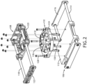
- FIG. 2 shows an exploded view of the motion assembly 100.
- the first subassembly 106 includes a platform 112 translatably mounted to spaced beams 114, such as cylindrical beam tubes.
- the spaced beams 114 may be attached to opposing frame elements 116, such as frame elements forming part of or attached to the seat tracks.
- the first platform 112 slides along the spaced beams 114, and the length of the spaced beams 114 determines the amount of travel of the platform 112.
- the motion of the platform 112 is linear and parallel to the spaced beams 114.
- the spaced beams 114 When equipped on the passenger seat, the spaced beams 114 may be oriented parallel to the passenger seat longitudinal axis such that the linear motion operates to move the seat forward or backward.
- the second subassembly 108 also includes spaced beams 118 and a second platform 120.
- the spaced beams 118 may also be cylindrical beam tubes.
- the spaced beams 118 are configured to translate relative to the second platform 120.
- the spaced beams 118 may be attached to frame elements 122, such as frame elements attached to or forming part of the passenger seat.
- the spaced beams 118 may initially be oriented parallel to the spaced beams 114 of the first subassembly, and after rotational motion from the third subassembly 100, the spaced beams 118 may be oriented at an angle to the spaced beams 114. In some embodiments, the angle may be about 90 degrees to move the seat laterally as compared to the first linear motion.
- the third subassembly 110 includes a swivel plate 124 mounted to the first platform 112 of the first subassembly 106, and a swivel ring 126 rotatably mounted to the swivel plate 124.
- the swivel ring 126 is mounted to the second platform 120 of the second subassembly 108.
- the second platform 120 of the second subassembly 108 can be rotated relative to the first platform 112 of the first subassembly 106 such that the spaced beams 118 of the second subassembly 108 can be angled relative to the spaced beams 114 of the first subassembly 106.
- This configuration provides linear motion in two different directions, with back-and-forth motion in each direction.
- the passenger seat can be moved from a first location to a second location along a travel path that includes motion in at least two different directions.
- first fasteners 128 may be used to secure the swivel plate 124 to the first platform 112, and second fasteners 130 may be used to secure the swivel ring 126 to the second platform 120.
- Each of the first and second fasteners 128, 130 may be externally threaded bolts received through their respective swivel element and tightened with internally threaded nuts.
- the first fasteners 128 may be used to secure the fixed swivel plate 124 to the first platform 112
- the second fasteners 130 may be used to secure the rotatable swivel ring 126 to the second platform 120.
- Spacers 132 may be used to provide the required space between the fixed swivel plate 124 and the second platform 120 to permit rotation.
- FIG. 3 illustrates the first subassembly 106 and the back-and-forth linear motion of the first platform 112 along the spaced beams 114.
- the motion can be achieved using a linear actuator coupled between the platform and the spaced beams 114 or the opposing frame elements 116.
- the linear actuator operates to translate the platform along the spaced beams 114.
- a similar linear actuator configuration can also be used to control linear motion of the second subassembly.
- FIG. 4 illustrates the third subassembly 110.
- the swivel ring 126 is configured to rotate within the swivel plate 124.
- the swivel ring 126 has a radially extending feature 134 and the swivel plate 124 has an annular track 136 of a predetermined length determinative of an amount of rotation of the swivel ring 126 relative to the swivel plate 124.
- the radially extending feature 134 is configured, as the swivel ring 126 rotates relative to the swivel plate 124, to travel within the annular track 136.
- the length of the annular track 136 can be customized to control the maximum allowable rotation of the swivel ring 126 relative to the swivel plate 124 and consequently the maximum angle between the first and second directions.
- the position of the annular track 136 on the swivel plate 124 can also be customized to control the start and stop angles of the second subassembly relative to the first subassembly.
- an actuator capable of rotational motion can be used to control rotation of the swivel ring 126 relative to the swivel plate 124, for example through the action of a Scotch yoke mechanism.
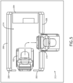
- FIGS. 5-7 illustrate a particular application of the motion assembly 100 equipped on a passenger seat 102 positioned in a passenger suite 200.
- the passenger suite 200 includes a plurality of upstanding walls, for instance a back wall 202, a front wall 204, and two opposing lateral walls 206, 208.
- a suite entrance 210 may be provided through one of the lateral walls 206, 208.
- the passenger suite 200 may be positioned alongside an aisle 212, for instance an aircraft longitudinal aisle.
- the upstanding walls define an interior space 214.
- the passenger seat 102 is positioned in the interior space 214.
- the passenger seat 102 is movable, by way of the motion assembly described above, between a first position and a second position.
- the first position corresponds to a travel position for taxi, takeoff, and landing (TTOL) and flight.
- the second position corresponds to a transfer position in which the passenger seat 102 is positioned within the suite entrance 210.
- "within the suite entrance” refers to a position in which the seat is physically within the suite entrance or adjacent to the suite entrance for instance in the aisle 212, at least partway.
- the transfer position is used to position the passenger seat 102 in or near the aisle so that a transfer wheelchair can be parked next to the passenger seat 102 to facilitate transfer and a short transfer distance.
- the motion path of the passenger seat 102 include both linear and rotational motions. More particularly, a first linear motion is provided by the first subassembly (106 in FIG. 1 ) to move the passenger seat 102 from the first position against the back wall 202 to a position laterally aligned with the suite entrance 210. A rotational motion is provided by the third subassembly (110 in FIG. 1 ) to rotate the passenger seat 102 approximately 90 degrees so that the passenger seat 102 faces the suite entrance 210. A second linear motion is provided by the second subassembly (108 in FIG. 1 ) to move the seat into the suite entrance 210, for instance at least partway into the aisle 212.
- the linear and rotational motions may be performed in sequence wherein the next motion does not start until the previous motion ceases. In other embodiments, at least some of the motions may overlap.
- the range of motions and angles may be customized depending of the dimensions of the passenger suite, distance to alignment of the passenger seat 102 with the suite entrance 210, etc.
- FIG. 6 illustrates an alternative motion path without rotational motion changing the facing direction of the passenger seat 102.
- This motion path may be utilized, for example, when the aisle does not have sufficient width to accommodate a lateral facing passenger seat transfer and/or the suite entrance 210 is wide enough to accommodate a forward-facing passenger seat 102.
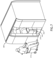
- FIGS. 7 and 8 illustrate the first and second positions of the passenger seat 102 relative to the passenger suite 200 and the transfer wheelchair 214 positioned in the aisle proximal to the suite entrance 210.
- a controller is programmed to operate the actuators associated with the first, second and third subassemblies 106, 108, 110 according to preprogrammed instructions.
- the controller may include at least one processor, memory, and a communication interface.
- the processor provides processing functionality for at least the controller and may include any number of processors, micro-controllers, circuitry, field programmable gate array (FPGA) or other processing systems, and resident or external memory for storing data, executable code, and other information accessed or generated by the controller.
- the processor may execute one or more software programs embodied in a non-transitory computer readable medium (e.g., memory) that implements techniques described herein.
- the processor is not limited by the materials from which it is formed, or the processing mechanisms employed therein and, as such, can be implemented via semiconductor(s) and/or transistors (e.g., using electronic integrated circuit (IC) components), and so forth.
- inventive concepts disclosed herein are well adapted to achieve the objectives and to attain the advantages mentioned herein as well as those inherent in the inventive concepts disclosed herein. While presently preferred embodiments of the inventive concepts disclosed herein have been described for purposes of this disclosure, it will be understood that numerous changes may be made which will readily suggest themselves to those skilled in the art and which are accomplished within the broad scope and coverage of the inventive concepts disclosed and claimed herein.
Landscapes
- Engineering & Computer Science (AREA)
- Aviation & Aerospace Engineering (AREA)
- Transportation (AREA)
- Mechanical Engineering (AREA)
- Seats For Vehicles (AREA)
Abstract
A motion assembly (100) for moving a passenger seat (102) from a first location to a second location, for instance to facilitate seating persons with reduced mobility. In embodiments, the motion assembly (100) includes a first subassembly (106) for linear motion in a first direction, a second subassembly (108) for linear motion in a second direction, and a third subassembly (110) for rotational motion, the third subassembly (110) positioned between and interconnecting the first and second subassemblies (106, 108), wherein an amount of rotational motion of the third subassembly (110) determines an angle of the second direction relative to the first direction. In some embodiments, the passenger seat (102) is located in a suite (200) and requires motion in at least two directions to move the seat (102) from within the suite (200) to the suite entrance (210).
Description
- The present disclosure relates generally to travel accommodations for persons with reduced mobility (PRM), and more particularly, to a motion assembly for a passenger seat configured to move the passenger seat in at least two directions to facilitate seating a PRM. In some embodiments, the motion assembly operates to move a passenger seat from a first location within a passenger suite to a second location within the suite entrance to facilitate passenger transfer at the aisle.
- Persons with reduced mobility (PRM) require special equipment and crew assistance when transferring from a wheelchair to an approved passenger seat. In the case of airliners, transfer wheelchairs may be used to navigate narrow aisles when boarding and deplaning a PRM. Seats for accommodating a PRM are typically located at the end of a seat row adjacent to an aisle for convenient transfer. In use, the seat armrest may be configured to lower to seat bottom level to facilitate lateral transfer from the wheelchair to the passenger seat.
- Some airliners may be equipped with premium class cabins including individual passenger suites. Such passenger suites may include a suite entrance positioned apart from and at an angle to a passenger seat within the suite. For example, in a particular suite configuration, the passenger seat may be positioned along one suite wall and oriented in one direction, while the suite entrance may be provided through a different wall and opening in a different direction. Such a suite configuration does not allow for direct transfer from a wheelchair to the passenger seat considering the distance and angle of the passenger seat relative to the suite entrance. In such a configuration, crew assistance is needed to physically lift and move the passenger from the transfer wheelchair to the passenger seat within the suite, which is disruptive to the PRM and invites injury to both the PRM and cabin crew.
- Therefore, what is needed is a mechanism for moving a passenger seat from one location to a temporary transfer location to facilitate PRM transfer at a safer and more convenient location.
- In one aspect, embodiments of the inventive concepts disclosed herein are directed to a motion assembly for a passenger seat. In embodiments, the motion assembly includes a first subassembly for linear motion in a first direction, a second subassembly for linear motion in a second direction, and a third subassembly for rotational motion, the third subassembly positioned between and interconnecting the first and second subassemblies, wherein an amount of rotational motion of the third subassembly determines an angle of the second direction relative to the first direction.
- In some embodiments, the first subassembly includes a platform translatably mounted to spaced beams, the third subassembly includes a swivel plate mounted to the platform and a swivel ring rotatably mounted to the swivel plate, and the second subassembly includes a platform mounted to the swivel ring and spaced beams translatably mounted to the platform.
- In some embodiments, the spaced beams of the first subassembly are components of a first frame assembly attachable to seat tracks, and the spaced beams of the second subassembly are components of a second frame assembly attachable to the passenger seat.
- In some embodiments, the swivel ring is configured to rotate within the swivel plate, the swivel ring has a radially extending feature, the swivel plate has an annular track of a predetermined length determinative of an amount of rotation of the swivel ring relative to the swivel plate, and the radially extending feature is configured, as the swivel ring rotates relative to the swivel plate, to travel within the annular track.
- In some embodiments, the third subassembly is configured for up to 90-degrees of rotation such that the second direction is orthogonal to the first direction.
- In some embodiments, the motion assembly is configured for sequential operation in that the first subassembly is configured to operate first to provide linear motion in the first direction, the third subassembly is configured to operate second to provide rotational motion, and the second assembly is configured to operate third to provide linear motion in the second direction.
- In some embodiments, the third subassembly is configured to operate after linear motion of the first subassembly ceases, and the second subassembly is configured to operate after rotational motion of the third subassembly ceases.
- According to another aspect, the inventive concepts disclosed herein are directed to a passenger seat assembly. In embodiments, the passenger seat assembly includes a passenger seat, seat tracks, and a motion assembly coupled between the passenger seat and the seat tracks. In embodiments, the motion assembly includes a first subassembly for linear motion in a first direction, the first subassembly coupled to the seat tracks, a second subassembly for linear motion in a second direction, the second subassembly coupled to the passenger seat, and a third subassembly for rotational motion, the third subassembly positioned between and interconnecting the first and second subassemblies, wherein an amount of rotational motion of the third subassembly determines an angle of the second direction relative to the first direction.
- According to a further aspect, the inventive concepts disclosed herein are directed to a passenger suite. In embodiments, the passenger suite includes upstanding walls defining an interior space, an entrance provided through one of the upstanding walls, and a passenger seat positioned within the interior space. In embodiments, the passenger seat includes a motion assembly configured to move the passenger seat from a first position within the interior space to a second position within the entrance, wherein movement from the first position to the second position includes at least one direction change. In embodiments, the motion assembly includes a first subassembly for linear motion in a first direction, the first subassembly coupled to seat tracks of the passenger seat, a second subassembly for linear motion in a second direction, the second subassembly coupled to the passenger seat, and a third subassembly for rotational motion, the third subassembly positioned between and interconnecting the first and second subassemblies, wherein an amount of rotational motion of the third subassembly determines an angle of the second direction relative to the first direction.
- This summary is provided solely as an introduction to subject matter that is fully described in the following detailed description and drawing figures. This summary should not be considered to describe essential features nor be used to determine the scope of the claims. Moreover, it is to be understood that both the foregoing summary and the following detailed description are explanatory only and are not necessarily restrictive of the subject matter claimed.
- Implementations of the inventive concepts disclosed herein may be better understood when consideration is given to the following detailed description thereof. Such description refers to the included drawings, which are not necessarily to scale, and in which some features may be exaggerated and some features may be omitted or may be represented schematically in the interest of clarity. Like reference numerals in the drawings may represent and refer to the same or similar element, feature, or function. In the drawings:
-
FIG. 1 is an isometric view of a motion assembly for a passenger seat, in accordance with example embodiments of this disclosure; -
FIG. 2 is an exploded view of the motion assembly shown inFIG. 1 ; -
FIG. 3 is an isometric view of a linear motion subassembly of the assembly shown inFIG. 1 ; -
FIG. 4 is an isometric view of a rotational motion subassembly of the assembly shown inFIG. 1 ; -
FIG. 5 is an overhead plan view of a passenger suite showing a passenger seat in each of a travel and a temporary transfer position, and a motion path of the passenger seat; -
FIG. 6 is an overhead plan view of a passenger suite showing a passenger seat in each of a travel and a temporary transfer position of a different orientation, and a motion path of the passenger seat; -
FIG. 7 is a perspective view of a passenger suite showing a passenger seat in a travel position; and -
FIG. 8 is a perspective view of a passenger suite showing a passenger seat in a transfer position within the suite entrance. - Before explaining at least one embodiment of the inventive concepts disclosed herein in detail, it is to be understood that the inventive concepts are not limited in their application to the details of construction and the arrangement of the components or steps or methodologies set forth in the following description or illustrated in the drawings. In the following detailed description of embodiments of the instant inventive concepts, numerous specific details are set forth in order to provide a more thorough understanding of the inventive concepts. However, it will be apparent to one of ordinary skill in the art having the benefit of the instant disclosure that the inventive concepts disclosed herein may be practiced without these specific details. In other instances, well-known features may not be described in detail to avoid unnecessarily complicating the instant disclosure. The inventive concepts disclosed herein are capable of other embodiments or of being practiced or carried out in various ways. Also, it is to be understood that the phraseology and terminology employed herein is for the purpose of description and should not be regarded as limiting.
- As used herein, a letter following a reference numeral is intended to reference an embodiment of the feature or element that may be similar, but not necessarily identical, to a previously described element or feature bearing the same reference numeral (e.g., 1, 1a, 1b). Such shorthand notations are used for purposes of convenience only, and should not be construed to limit the inventive concepts disclosed herein in any way unless expressly stated to the contrary.
- Further, unless expressly stated to the contrary, "or" refers to an inclusive or and not to an exclusive or. For example, a condition A or B is satisfied by anyone of the following: A is true (or present) and B is false (or not present), A is false (or not present) and B is true (or present), and both A and B are true (or present).
- In addition, use of the "a" or "an" are employed to describe elements and components of embodiments of the instant inventive concepts. This is done merely for convenience and to give a general sense of the inventive concepts, and "a" and "an" are intended to include one or at least one and the singular also includes the plural unless it is obvious that it is meant otherwise.
- Finally, as used herein any reference to "one embodiment" or "some embodiments" means that a particular element, feature, structure, or characteristic described in connection with the embodiment is included in at least one embodiment of the inventive concepts disclosed herein. The appearances of the phrase "in some embodiments" in various places in the specification are not necessarily all referring to the same embodiment, and embodiments of the inventive concepts disclosed may include one or more of the features expressly described or inherently present herein, or any combination of sub-combination of two or more such features, along with any other features which may not necessarily be expressly described or inherently present in the instant disclosure.
- Broadly, embodiments of the inventive concepts disclosed herein are directed to a motion assembly for a passenger seat, a passenger seat including a motion assembly, and a passenger suite including a passenger suite equipped with a motion assembly. In some implementations, the passenger seat is a premium class passenger seat in an airliner. In use, the motion assembly is capable of moving the passenger seat between a first position and a second position, wherein the first position corresponds to the travel position of the seat and the second position corresponds to a temporary position, for instance to position the passenger seat in a location convenient for transferring a PRM passenger from a wheelchair to the passenger seat. In some implementations, the second position is within a suite entrance at the aisle.
- In embodiments, the motion assembly includes linear motion subassemblies coupled through a rotational motion subassembly. A first linear motion subassembly operates to provide linear motion in a first direction. The rotational motion subassembly operates to rotate a second linear motion subassembly relative to the first linear motion subassembly. The second linear motion subassembly operates to provide linear motion in a second direction different from the first direction. For example, the first linear motion subassembly may operate to translate a passenger seat in a forward direction, the rotational motion subassembly may operate to rotate the passenger seat, and the second linear motion subassembly may operate to translate the passenger seat in a lateral direction relative to the forward direction. As such, the motion assembly can operate to move a seat from its travel location within a suite to a suite entrance while also rotating the seat to an orientation convenient for PRM transfer.
-
FIG. 1 illustrates amotion assembly 100 according to the present disclosure. Themotion assembly 100 operates to move an object from a first location to at least one second location along at least one motion path. According to the present disclosure, themotion assembly 100 is configured to move a passenger seat. Themotion assembly 100 is coupled between the passenger seat (see 102 inFIG. 7 ) and fixed seat tracks (see 104 inFIG. 7 ) in the case of an airliner passenger seat. Thepassenger seat 102 generally includes frame elements supporting a seat bottom and a backrest, and in some embodiments at least one armrest. The seat tracks 104 generally include structure fixed to the floor. Themotion assembly 100 operates to move thepassenger seat 102 relative to the seat tracks 104. - As shown in
FIG. 1 , themotion assembly 100 generally includes afirst subassembly 106 for providing linear motion in a first direction, asecond subassembly 108 for providing linear motion in a second direction, and athird subassembly 110 for providing rotational motion between the first andsecond subassemblies third subassembly 110 is positioned between and interconnects the first andsecond subassemblies third subassembly 110 determines an angle of the second direction relative to the first direction. As shown, the third subassembly is mounted atop thefirst subassembly 106, thesecond subassembly 108 is mounted atop thethird subassembly 110, and thethird subassembly 110 is configured to provide rotational motion up to about 90 degrees such that the linear motion of thesecond subassembly 108 can be made perpendicular to the linear motion of thefirst subassembly 106. -
FIG. 2 shows an exploded view of themotion assembly 100. In embodiments, thefirst subassembly 106 includes aplatform 112 translatably mounted to spacedbeams 114, such as cylindrical beam tubes. The spaced beams 114 may be attached to opposingframe elements 116, such as frame elements forming part of or attached to the seat tracks. As shown, thefirst platform 112 slides along the spacedbeams 114, and the length of the spacedbeams 114 determines the amount of travel of theplatform 112. The motion of theplatform 112 is linear and parallel to the spaced beams 114. When equipped on the passenger seat, the spacedbeams 114 may be oriented parallel to the passenger seat longitudinal axis such that the linear motion operates to move the seat forward or backward. - In embodiments, the
second subassembly 108 also includes spacedbeams 118 and asecond platform 120. The spaced beams 118 may also be cylindrical beam tubes. In thesecond subassembly 108, the spacedbeams 118 are configured to translate relative to thesecond platform 120. The spaced beams 118 may be attached to frameelements 122, such as frame elements attached to or forming part of the passenger seat. When equipped on the passenger seat, the spacedbeams 118 may initially be oriented parallel to the spacedbeams 114 of the first subassembly, and after rotational motion from thethird subassembly 100, the spacedbeams 118 may be oriented at an angle to the spaced beams 114. In some embodiments, the angle may be about 90 degrees to move the seat laterally as compared to the first linear motion. - In embodiments, the
third subassembly 110 includes aswivel plate 124 mounted to thefirst platform 112 of thefirst subassembly 106, and aswivel ring 126 rotatably mounted to theswivel plate 124. Theswivel ring 126 is mounted to thesecond platform 120 of thesecond subassembly 108. By mounting theswivel plate 124 and theswivel ring 126 to the two separate first andsecond platforms second platform 120 of thesecond subassembly 108 can be rotated relative to thefirst platform 112 of thefirst subassembly 106 such that the spacedbeams 118 of thesecond subassembly 108 can be angled relative to the spacedbeams 114 of thefirst subassembly 106. This configuration provides linear motion in two different directions, with back-and-forth motion in each direction. When equipped on the passenger seat, the passenger seat can be moved from a first location to a second location along a travel path that includes motion in at least two different directions. - In embodiments,
first fasteners 128 may be used to secure theswivel plate 124 to thefirst platform 112, andsecond fasteners 130 may be used to secure theswivel ring 126 to thesecond platform 120. Each of the first andsecond fasteners first fasteners 128 may be used to secure the fixedswivel plate 124 to thefirst platform 112, and thesecond fasteners 130 may be used to secure therotatable swivel ring 126 to thesecond platform 120.Spacers 132 may be used to provide the required space between the fixedswivel plate 124 and thesecond platform 120 to permit rotation. -
FIG. 3 illustrates thefirst subassembly 106 and the back-and-forth linear motion of thefirst platform 112 along the spaced beams 114. Although not shown, the motion can be achieved using a linear actuator coupled between the platform and the spacedbeams 114 or the opposingframe elements 116. In use, the linear actuator operates to translate the platform along the spaced beams 114. A similar linear actuator configuration can also be used to control linear motion of the second subassembly. -
FIG. 4 illustrates thethird subassembly 110. In embodiments, theswivel ring 126 is configured to rotate within theswivel plate 124. Theswivel ring 126 has aradially extending feature 134 and theswivel plate 124 has anannular track 136 of a predetermined length determinative of an amount of rotation of theswivel ring 126 relative to theswivel plate 124. Theradially extending feature 134 is configured, as theswivel ring 126 rotates relative to theswivel plate 124, to travel within theannular track 136. The length of theannular track 136 can be customized to control the maximum allowable rotation of theswivel ring 126 relative to theswivel plate 124 and consequently the maximum angle between the first and second directions. The position of theannular track 136 on theswivel plate 124 can also be customized to control the start and stop angles of the second subassembly relative to the first subassembly. Although not shown, an actuator capable of rotational motion can be used to control rotation of theswivel ring 126 relative to theswivel plate 124, for example through the action of a Scotch yoke mechanism. -
FIGS. 5-7 illustrate a particular application of themotion assembly 100 equipped on apassenger seat 102 positioned in apassenger suite 200. In a non-limiting example, thepassenger suite 200 includes a plurality of upstanding walls, for instance aback wall 202, afront wall 204, and two opposinglateral walls suite entrance 210 may be provided through one of thelateral walls passenger suite 200 may be positioned alongside anaisle 212, for instance an aircraft longitudinal aisle. - The upstanding walls define an
interior space 214. Thepassenger seat 102 is positioned in theinterior space 214. As shown, thepassenger seat 102 is movable, by way of the motion assembly described above, between a first position and a second position. In embodiments, the first position corresponds to a travel position for taxi, takeoff, and landing (TTOL) and flight. In other words, the "regular" location of thepassenger seat 102 within thepassenger suite 200. The second position corresponds to a transfer position in which thepassenger seat 102 is positioned within thesuite entrance 210. As used herein, "within the suite entrance" refers to a position in which the seat is physically within the suite entrance or adjacent to the suite entrance for instance in theaisle 212, at least partway. The transfer position is used to position thepassenger seat 102 in or near the aisle so that a transfer wheelchair can be parked next to thepassenger seat 102 to facilitate transfer and a short transfer distance. - As shown in
FIG. 5 , the motion path of thepassenger seat 102 include both linear and rotational motions. More particularly, a first linear motion is provided by the first subassembly (106 inFIG. 1 ) to move thepassenger seat 102 from the first position against theback wall 202 to a position laterally aligned with thesuite entrance 210. A rotational motion is provided by the third subassembly (110 inFIG. 1 ) to rotate thepassenger seat 102 approximately 90 degrees so that thepassenger seat 102 faces thesuite entrance 210. A second linear motion is provided by the second subassembly (108 inFIG. 1 ) to move the seat into thesuite entrance 210, for instance at least partway into theaisle 212. In embodiments, the linear and rotational motions may be performed in sequence wherein the next motion does not start until the previous motion ceases. In other embodiments, at least some of the motions may overlap. The range of motions and angles may be customized depending of the dimensions of the passenger suite, distance to alignment of thepassenger seat 102 with thesuite entrance 210, etc. -
FIG. 6 illustrates an alternative motion path without rotational motion changing the facing direction of thepassenger seat 102. This motion path may be utilized, for example, when the aisle does not have sufficient width to accommodate a lateral facing passenger seat transfer and/or thesuite entrance 210 is wide enough to accommodate a forward-facingpassenger seat 102. -
FIGS. 7 and8 illustrate the first and second positions of thepassenger seat 102 relative to thepassenger suite 200 and thetransfer wheelchair 214 positioned in the aisle proximal to thesuite entrance 210. - In some embodiments, a controller is programmed to operate the actuators associated with the first, second and
third subassemblies - From the above description, it is clear that the inventive concepts disclosed herein are well adapted to achieve the objectives and to attain the advantages mentioned herein as well as those inherent in the inventive concepts disclosed herein. While presently preferred embodiments of the inventive concepts disclosed herein have been described for purposes of this disclosure, it will be understood that numerous changes may be made which will readily suggest themselves to those skilled in the art and which are accomplished within the broad scope and coverage of the inventive concepts disclosed and claimed herein.
Claims (9)
- A motion assembly (100) for a passenger seat (102), comprising:a first subassembly (106) for linear motion in a first direction;a second subassembly (108) for linear motion in a second direction; anda third subassembly (110) for rotational motion, the third subassembly (110) positioned between and interconnecting the first and second subassemblies (106, 108), wherein an amount of rotational motion of the third subassembly (110) determines an angle of the second direction relative to the first direction.
- The motion assembly (100) according to claim 1, wherein:the first subassembly (106) comprises a platform (112) translatably mounted to spaced beams (114);the third subassembly (110) comprises a swivel plate (124) mounted to the platform (112) and a swivel ring (126) rotatably mounted to the swivel plate (124); andthe second subassembly (108) comprises a platform (120) mounted to the swivel ring (126) and spaced beams (118) translatably mounted to the platform (120).
- The motion assembly (100) according to claim 2, wherein:the spaced beams (114) of the first subassembly (106) are components of a first frame assembly attachable to seat tracks; andthe spaced beams (118) of the second subassembly (108) are components of a second frame assembly attachable to the passenger seat.
- The motion assembly (100) according to claim 2, wherein:the swivel ring (126) is configured to rotate within the swivel plate (124);the swivel ring (126) has a radially extending feature (134);the swivel plate (124) has an annular track of a predetermined length determinative of an amount of rotation of the swivel ring (126) relative to the swivel plate (124); andthe radially extending feature (134) is configured, as the swivel ring (126) rotates relative to the swivel plate (124), to travel within the annular track.
- The motion assembly (100) according to claim 1, wherein the third subassembly (110) is configured for up to 90-degrees of rotation such that the second direction is orthogonal to the first direction.
- The motion assembly (100) according to claim 1, wherein the motion assembly (100) is configured for sequential operation in that the first subassembly (106) is configured to operate first to provide linear motion in the first direction, the third subassembly (110) is configured to operate second to provide rotational motion, and the second assembly (108) is configured to operate third to provide linear motion in the second direction.
- The motion assembly (100) according to claim 6, wherein the third subassembly (110) is configured to operate after linear motion of the first subassembly (106) ceases, and the second subassembly (108) is configured to operate after rotational motion of the third subassembly (110) ceases.
- A passenger seat assembly, comprising:a passenger seat (102);seat tracks (104); anda motion assembly (100), as claimed in any preceding claim, coupled between the passenger seat (102) and the seat tracks (104), wherein the first subassembly (106) is coupled to the seat tracks (104), and wherein the second subassembly (108) is coupled to the passenger seat (102).
- A passenger suite (200), comprising:upstanding walls (202, 204, 206) defining an interior space;an entrance (210) provided through one of the upstanding walls; anda passenger seat (102) positioned within the interior space, the passenger seat (102) comprising a motion assembly (100), as claimed in any of claims 1-7, configured to move the passenger seat (102) from a first position within the interior space to a second position within the entrance (210), wherein movement from the first position to the second position includes at least one direction change, and the first subassembly (106) is coupled to seat tracks (104) of the passenger seat (102), and wherein the second subassembly (108) is coupled to the passenger seat (102).
Applications Claiming Priority (2)
| Application Number | Priority Date | Filing Date | Title |
|---|---|---|---|
| IN202311046247 | 2023-07-10 | ||
| US18/410,151 US20250018837A1 (en) | 2023-07-10 | 2024-01-11 | Passenger suite access for persons with reduced mobility |
Publications (1)
| Publication Number | Publication Date |
|---|---|
| EP4491515A1 true EP4491515A1 (en) | 2025-01-15 |
Family
ID=91621081
Family Applications (1)
| Application Number | Title | Priority Date | Filing Date |
|---|---|---|---|
| EP24183560.2A Pending EP4491515A1 (en) | 2023-07-10 | 2024-06-20 | Passenger suite access for persons with reduced mobility |
Country Status (1)
| Country | Link |
|---|---|
| EP (1) | EP4491515A1 (en) |
Citations (7)
| Publication number | Priority date | Publication date | Assignee | Title |
|---|---|---|---|---|
| WO2006041570A1 (en) * | 2004-10-08 | 2006-04-20 | B/E Aerospace, Inc. | Moveable seat with tapered swivel assembly and cable track wheel |
| US7399035B2 (en) * | 2003-02-19 | 2008-07-15 | Toyota Shatai Kabushiki Kaisha | Seat for vehicle |
| DE102015109550A1 (en) * | 2014-06-25 | 2015-12-31 | Ford Global Technologies, Llc | Automatic presentable swivel seat |
| EP3281873B1 (en) * | 2016-08-11 | 2020-04-01 | Goodrich Corporation | Brake release for aircraft seat |
| GB2590751A (en) * | 2017-12-12 | 2021-07-07 | Ipeco Holdings Ltd | Mounting apparatus for a seat |
| US11542014B2 (en) * | 2017-09-12 | 2023-01-03 | Rockwell Collins, Inc. | Gravity-assisted tracking base assembly for aircraft seat |
| EP4140888A1 (en) * | 2021-08-27 | 2023-03-01 | B/E Aerospace, Inc. | Passenger seat arrangement for socialization and access for persons of reduced mobility |
-
2024
- 2024-06-20 EP EP24183560.2A patent/EP4491515A1/en active Pending
Patent Citations (7)
| Publication number | Priority date | Publication date | Assignee | Title |
|---|---|---|---|---|
| US7399035B2 (en) * | 2003-02-19 | 2008-07-15 | Toyota Shatai Kabushiki Kaisha | Seat for vehicle |
| WO2006041570A1 (en) * | 2004-10-08 | 2006-04-20 | B/E Aerospace, Inc. | Moveable seat with tapered swivel assembly and cable track wheel |
| DE102015109550A1 (en) * | 2014-06-25 | 2015-12-31 | Ford Global Technologies, Llc | Automatic presentable swivel seat |
| EP3281873B1 (en) * | 2016-08-11 | 2020-04-01 | Goodrich Corporation | Brake release for aircraft seat |
| US11542014B2 (en) * | 2017-09-12 | 2023-01-03 | Rockwell Collins, Inc. | Gravity-assisted tracking base assembly for aircraft seat |
| GB2590751A (en) * | 2017-12-12 | 2021-07-07 | Ipeco Holdings Ltd | Mounting apparatus for a seat |
| EP4140888A1 (en) * | 2021-08-27 | 2023-03-01 | B/E Aerospace, Inc. | Passenger seat arrangement for socialization and access for persons of reduced mobility |
Similar Documents
| Publication | Publication Date | Title |
|---|---|---|
| US11542014B2 (en) | Gravity-assisted tracking base assembly for aircraft seat | |
| EP3778395B1 (en) | Restraint assembly for cargo system | |
| EP2877399B1 (en) | Slider seat for aircraft | |
| EP2620366B1 (en) | Vehicle crewstation seat assembly | |
| US10342338B2 (en) | Stowage module mounted tray table with multi-bar linkage driven movement | |
| EP3156331A1 (en) | Deployable door-mounted seat | |
| US10858111B2 (en) | Passenger seat reconfigureable for seating or storage | |
| EP3388342B1 (en) | Seat assembly using j-track seats | |
| US20250018837A1 (en) | Passenger suite access for persons with reduced mobility | |
| US10577109B2 (en) | System and method for deplaning and boarding airplanes | |
| EP4227219A1 (en) | Use of forward closet in single aisle aircraft for wheelchair accommodation | |
| EP3778394B1 (en) | Restraint assembly for cargo system | |
| US12090097B2 (en) | Platform system for securing a wheelchair in position within an internal cabin of a vehicle | |
| US4416579A (en) | Power-actuated low profile cargo guide | |
| EP4253243A1 (en) | Vehicle seating rows for increasing cross aisle space | |
| EP4140888B1 (en) | Passenger seat arrangement for socialization and access for persons of reduced mobility | |
| EP4488562B1 (en) | Portable electronic device holder with socket and rotating partial-cylinder | |
| EP4600153A1 (en) | Passenger seat with decoupling motion mechanism for reduced mobility seating | |
| US12325522B1 (en) | Movable wall section for reduced mobility passenger access | |
| TR2022020899A2 (en) | A CARRYING SYSTEM INCLUDING A CENTERING ELEMENT | |
| TR2022020915A2 (en) | A CARRYING SYSTEM WITH AN IMPROVED LIFTING MECHANISM FOR USE IN AIRCRAFT | |
| CA3244986A1 (en) | Pilot seat assembly with integrated rest position | |
| HK40019745B (en) | Passenger restraint for an amusement ride | |
| HK40019745A (en) | Passenger restraint for an amusement ride | |
| NO344012B1 (en) | Portable and foldable aeronautical workstation |
Legal Events
| Date | Code | Title | Description |
|---|---|---|---|
| PUAI | Public reference made under article 153(3) epc to a published international application that has entered the european phase |
Free format text: ORIGINAL CODE: 0009012 |
|
| STAA | Information on the status of an ep patent application or granted ep patent |
Free format text: STATUS: THE APPLICATION HAS BEEN PUBLISHED |
|
| AK | Designated contracting states |
Kind code of ref document: A1 Designated state(s): AL AT BE BG CH CY CZ DE DK EE ES FI FR GB GR HR HU IE IS IT LI LT LU LV MC ME MK MT NL NO PL PT RO RS SE SI SK SM TR |
|
| STAA | Information on the status of an ep patent application or granted ep patent |
Free format text: STATUS: REQUEST FOR EXAMINATION WAS MADE |
|
| 17P | Request for examination filed |
Effective date: 20250513 |
|
| STAA | Information on the status of an ep patent application or granted ep patent |
Free format text: STATUS: EXAMINATION IS IN PROGRESS |