EP4491498A1 - Joint structure for vehicle body cover in straddled vehicle - Google Patents
Joint structure for vehicle body cover in straddled vehicle Download PDFInfo
- Publication number
- EP4491498A1 EP4491498A1 EP23212568.2A EP23212568A EP4491498A1 EP 4491498 A1 EP4491498 A1 EP 4491498A1 EP 23212568 A EP23212568 A EP 23212568A EP 4491498 A1 EP4491498 A1 EP 4491498A1
- Authority
- EP
- European Patent Office
- Prior art keywords
- plate portions
- cover
- outer plate
- inner plate
- joint structure
- Prior art date
- Legal status (The legal status is an assumption and is not a legal conclusion. Google has not performed a legal analysis and makes no representation as to the accuracy of the status listed.)
- Granted
Links
Images







Classifications
-
- B—PERFORMING OPERATIONS; TRANSPORTING
- B62—LAND VEHICLES FOR TRAVELLING OTHERWISE THAN ON RAILS
- B62J—CYCLE SADDLES OR SEATS; AUXILIARY DEVICES OR ACCESSORIES SPECIALLY ADAPTED TO CYCLES AND NOT OTHERWISE PROVIDED FOR, e.g. ARTICLE CARRIERS OR CYCLE PROTECTORS
- B62J17/00—Weather guards for riders; Fairings or stream-lining parts not otherwise provided for
-
- B—PERFORMING OPERATIONS; TRANSPORTING
- B62—LAND VEHICLES FOR TRAVELLING OTHERWISE THAN ON RAILS
- B62K—CYCLES; CYCLE FRAMES; CYCLE STEERING DEVICES; RIDER-OPERATED TERMINAL CONTROLS SPECIALLY ADAPTED FOR CYCLES; CYCLE AXLE SUSPENSIONS; CYCLE SIDECARS, FORECARS, OR THE LIKE
- B62K11/00—Motorcycles, engine-assisted cycles or motor scooters with one or two wheels
-
- B—PERFORMING OPERATIONS; TRANSPORTING
- B62—LAND VEHICLES FOR TRAVELLING OTHERWISE THAN ON RAILS
- B62M—RIDER PROPULSION OF WHEELED VEHICLES OR SLEDGES; POWERED PROPULSION OF SLEDGES OR SINGLE-TRACK CYCLES; TRANSMISSIONS SPECIALLY ADAPTED FOR SUCH VEHICLES
- B62M7/00—Motorcycles characterised by position of motor or engine
Definitions
- the present invention relates to a joint structure for a vehicle body cover in a straddled vehicle.
- Some straddled vehicles are equipped with a vehicle body cover.
- the vehicle body cover is divided into a plurality of covers, which are joined to each other.
- the motorcycle disclosed in Japanese Utility Model Publication No. H6-15791 includes a front cover and an inner cover that are separate bodies from each other. Along the inner sides of the mating edges of these covers, one cover is provided with a plurality of locking holes, and the other cover is provided with a plurality of hooks. The front cover and the inner cover are joined to each other by locking these hooks into the locking holes.
- a straddled vehicle banks left and right while driving.
- the force that deforms the vehicle body cover acts in different directions. Therefore, the vehicle body cover for the straddled vehicle is required to have high joint strength in various directions.
- the joint strength in one direction is high, the joint strength in other directions is low.
- An object of the present invention is to provide flexibility of the vehicle body cover and to obtain high joint strength in different directions in a joint structure of a vehicle body cover in a straddled vehicle.
- One aspect of the present invention is a joint structure for a vehicle body cover in a straddled vehicle.
- the vehicle body cover includes a first cover and a second cover.
- the joint structure includes a plurality of first inner plate portions, a plurality of second inner plate portions, a plurality of first outer plate portions, a plurality of second outer plate portions, a plurality of first protrusions, and a plurality of first holes, a plurality of second protrusions, and a plurality of second holes.
- the plurality of first inner plate portions are arranged along a seam between the first cover and the second cover.
- the plurality of first inner plate portions are provided on the first cover.
- the plurality of second inner plate portions are arranged along the seam.
- the plurality of second inner plate portions are provided on the second cover.
- the plurality of first outer plate portions are arranged along the seam.
- the plurality of first outer plate portions are provided on the first cover.
- the plurality of first outer plate portions respectively overlap the plurality of second inner plate portions from an outside in a thickness direction of the first cover and the second cover.
- the plurality of second outer plate portions are arranged along the seam.
- the plurality of second outer plate portions are provided on the second cover.
- the plurality of second outer plate portions respectively overlap the plurality of first inner plate portions from the outside in the thickness direction.
- the plurality of first protrusions are provided on one of the plurality of first outer plate portions and the plurality of second inner plate portions respectively.
- the plurality of first holes are provided in the other of the plurality of first outer plate portions and the plurality of second inner plate portions respectively.
- the plurality of first holes are respectively engaged with the plurality of first protrusions.
- the plurality of second protrusions are provided on one of the plurality of first inner plate portions and the plurality of second outer plate portions respectively.
- the plurality of second holes are provided in the other of the plurality of first inner plate portions and the plurality of second outer plate portions respectively.
- the plurality of second holes are respectively engaged with the plurality of second protrusions.
- the plurality of first protrusions may be provided on the plurality of first outer plate portions respectively.
- the plurality of first holes may be provided in the plurality of second inner plate portions respectively.
- the plurality of second protrusions may be provided on the plurality of second outer plate portions respectively.
- the plurality of second holes may be provided in the plurality of first inner plate portions respectively.
- the plurality of first protrusions and the plurality of second holes may be alternately arranged along the seam in the first cover.
- the plurality of second protrusions and the plurality of first holes may be alternately arranged along the seam in the second cover. In this case, the first cover and the second cover are difficult to separate from each other while providing the flexibility of the vehicle body cover at the seam.
- the plurality of first outer plate portions and the plurality of second outer plate portions may each have a zigzag shape that meshes with each other in a extending direction in which the seam extends. In this case, high joint strength can be obtained even against deformation of the vehicle body cover in the extending direction of the seam.
- the plurality of first inner plate portions and the plurality of second inner plate portions may each have a zigzag shape that meshes with each other in the extending direction in which the seam extends. In this case, high joint strength can be obtained even against deformation of the vehicle body cover in the extending direction of the seam.
- the plurality of first outer plate portions and the plurality of second outer plate portions may be arranged alternately with each other along the seam. In this case, high joint strength can be obtained even against deformation of the vehicle body cover in the extending direction of the seam.
- the plurality of first outer plate portions and the plurality of second outer plate portions may be arranged flush on an outer surface of the vehicle body cover. In this case, compared to a case where a protrusion is provided on the outer surface of the vehicle body cover, the vehicle body cover is prevented from coming into contact with the road surface when the vehicle travels on a road surface with a step.
- the plurality of first inner plate portions and the plurality of second inner plate portions may be arranged alternately with each other along the seam. In this case, high joint strength can be obtained even against deformation of the vehicle body cover in the extending direction of the seam.
- the plurality of first protrusions may be provided on the plurality of first outer plate portions respectively.
- the plurality of first holes may be provided in the plurality of second inner plate portions respectively.
- the plurality of second protrusions may be provided on the plurality of first inner plate portions respectively.
- the plurality of second holes may be provided in the plurality of second outer plate portions respectively.
- the vehicle body cover may have a curved shape at the seam. In this case, high joint strength can be obtained even for the curved vehicle body cover.
- the vehicle body cover may be divided into the first cover and the second cover in a left-right direction of the straddled vehicle.
- the joint structure according to the present aspect provides flexibility and high joint strength.
- the straddled vehicle may include a front wheel.
- the joint structure may be located adjacent to the front wheel.
- the joint structure according to the present aspect provides high joint strength.
- the first cover and the second cover may be an undercover arranged behind the front wheel.
- the joint structure according to the present aspect provides high joint strength.
- the first cover and the second cover may be an inner panel arranged above the front wheel.
- the joint structure according to the present aspect provides high joint strength.
- Another aspect of the present invention is a straddled vehicle, which includes the above-described joint structure.
- FIG. 1 is a side view of a straddled vehicle 1 according to an embodiment.
- FIG. 2 is a front view of the straddled vehicle 1.
- the straddled vehicle 1 according to the present embodiment is a so-called full cowl type motorcycle.
- the straddled vehicle 1 includes a steering device 2, a front wheel 3, a fuel tank 4, a seat 5, an engine 6, a rear wheel 7, a rear arm 8, and a vehicle body cover 9.
- the front, rear, left, and right directions refer to the front, rear, left, and right directions as viewed from a rider seated on the seat 5.
- the steering device 2 is steered by a rider.
- the steering device 2 includes a front fork 11 and a handle member 12.
- the front fork 11 rotatably supports the front wheel 3.
- the handle member 12 is connected to the front fork 11.
- the front fork 11 includes a first suspension 13 and a second suspension 14.
- the fuel tank 4 is arranged behind the handle member 12.
- the seat 5 is arranged behind the fuel tank 4.
- the engine 6 is arranged between the front wheel 3 and the rear wheel 7.
- the engine 6 is arranged below the fuel tank 4.
- the engine 6 generates driving force that rotates the rear wheel 7.
- the rear wheel 7 is arranged behind the engine 6.
- the rear wheel 7 is rotatably supported by the rear arm 8.
- the vehicle body cover 9 includes a front cover 17, a first side cover 18, and a second side cover 19.
- the front cover 17 is arranged in front of the steering device 2.
- the first side cover 18 and the second side cover 19 extend rearward from the front cover 17.
- the first side cover 18 and the second side cover 19 cover the steering device 2 and the engine 6 from the left and right sides.
- the vehicle body cover 9 includes an inner panel 16 and an undercover 15.
- the inner panel 16 is arranged above the front wheel 3.
- the inner panel 16 is arranged close to the front wheel 3.
- the inner panel 16 is arranged inside the first side cover 18 and the second side cover 19.
- the undercover 15 is arranged behind the front wheel 3.
- the undercover 15 is arranged close to the front wheel 3.
- the undercover 15 is arranged below the first side cover 18 and the second side cover 19.
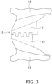
- FIG. 3 is a bottom view of the undercover 15.
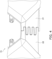
- FIGS. 4 and 5 are perspective views of the undercover 15.
- FIG. 4 shows a bottom surface of the undercover 15.
- FIG. 5 shows a top surface of the undercover 15.
- the undercover 15 includes a first cover 21 and a second cover 22.
- the first cover 21 and the second cover 22 are separate bodies from each other.
- the undercover 15 is divided into the first cover 21 and the second cover 22 in the left-right direction.
- the first cover 21 is arranged below the first side cover 18.
- the first cover 21 is connected to the first side cover 18.
- the second cover 22 is arranged below the second side cover 19.
- the second cover 22 is connected to the second side cover 19.
- the first cover 21 is arranged on the left side
- the second cover 22 is arranged on the right side.
- the first cover 21 may be arranged on the right side
- the second cover 22 may be arranged on the left side.
- the first cover 21 and the second cover 22 are joined to each other.
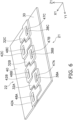
- FIGS. 6 and 7 are perspective views showing the joint structure between the first cover 21 and the second cover 22.
- FIG. 6 shows the top surfaces of the first cover 21 and the second cover 22.
- FIG. 7 shows the bottom surfaces of the first cover 21 and the second cover 22.
- FIG. 8 is a top view showing the joint structure between the first cover 21 and the second cover 22.
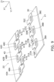
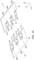
- FIGS. 9 and 10 are exploded perspective views showing the joint structure of the first cover 21 and the second cover 22.
- FIG. 9 shows the top surfaces of the first cover 21 and the second cover 22.
- FIG. 10 shows the bottom surfaces of the first cover 21 and the second cover 22.
- a direction in which a seam between the first cover 21 and the second cover 22 extends will be referred to as an extending direction Y1.
- a direction in which the first cover 21 and the second cover 22 face each other will be referred to as a joining direction X1.
- the extending direction Y1 corresponds to the front-rear direction of the straddled vehicle 1.
- the joining direction X1 corresponds to the left-right direction of the straddled vehicle 1.
- a thickness direction Z1 of the first cover 21 and the second cover 22 corresponds to the vertical direction of the straddled vehicle 1.
- the first cover 21 includes a first main plate portion 30, a plurality of first outer plate portions 31A to 31C, and a plurality of first inner plate portions 32A to 32C.
- the first main plate portion 30 has a flat shape. Alternatively, the first main plate portion 30 may have a curved shape.
- the plurality of first outer plate portions 31A to 31C and the plurality of first inner plate portions 32A to 32C protrude from the first main plate portion 30 in the joining direction X1.
- the plurality of first outer plate portions 31A to 31C are arranged in line in the extending direction Y1.
- the plurality of first inner plate portions 32A to 32C are arranged in line in the extending direction Y1.
- the plurality of first outer plate portions 31A to 31C and the plurality of first inner plate portions 32A to 32C are alternately arranged in line in the extending direction Y1.
- the plurality of first outer plate portions 31A to 31C are located on the outer side than the plurality of first inner plate portions 32A to 32C in the thickness direction Z1.
- FIG. 11 is a sectional view taken along line XI-XI in FIG. 8 .
- the inner surface 311 of the first outer plate portion 31A is located on the outer side than the inner surface 301 of the first main plate portion 30 in the thickness direction Z1.
- a stepped portion 303 is provided between the inner surface 311 of the first outer plate portion 31A and the inner surface 301 of the first main plate portion 30.
- the outer surface 312 of the first outer plate portion 31A is flush with the outer surface 302 of the first main plate portion 30.
- the other first outer plate portions 31B and 31C also have the same shape as the first outer plate portion 31A.
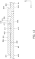
- FIG. 12 is a sectional view taken along line XII-XII in FIG. 8 .
- the inner surface 321 of the first inner plate portion 32A is located on the inner side than the inner surface 301 of the first main plate portion 30 in the thickness direction Z1.
- a stepped portion 304 is provided between the inner surface 321 of the first inner plate portion 32A and the inner surface 301 of the first main plate portion 30.
- the outer surface 322 of the first inner plate portion 32A is located on the inner side than the outer surface 302 of the first main plate portion 30 in the thickness direction Z1.
- the first inner plate portion 32A includes a first wide portion 33A and a first narrow portion 34A.
- the first narrow portion 34A protrudes from the first wide portion 33A in the joining direction X1.
- the first narrow portion 34A is smaller than the first wide portion 33A in the extending direction Y1. Therefore, a pair of first corner portions 35A and 36A are provided between the first narrow portion 34A and the first wide portion 33A.
- the pair of first corner portions 35A and 36A extend from the first narrow portion 34A in one direction and the other in the extending direction Y1, respectively.
- the other first inner plate portions 32B and 32C also have the same shape as the first inner plate portion 32A.
- the first inner plate portion 32B includes a first wide portion 33B and a first narrow portion 34B.
- a pair of first corner portions 35B and 36B are provided between the first wide portion 33B and the first narrow portion 34B.
- the first inner plate portion 32C includes a first wide portion 33C and a first narrow portion 34C.
- a pair of first corner portions 35C and 36C are provided between the first wide portion 33C and the first narrow portion 34C.
- the second cover 22 includes a second main plate portion 40, a plurality of second outer plate portions 41A to 41C, and a plurality of second inner plate portions 42A to 42C.
- the second main plate portion 40 has a flat shape. Alternatively, the second main plate portion 40 may have a curved shape.
- the plurality of second outer plate portions 41A to 41C and the plurality of second inner plate portions 42A to 42C protrude from the second main plate portion 40 in the joining direction X1.
- the plurality of second outer plate portions 41A to 41C are arranged in line in the extending direction Y1.
- the plurality of second inner plate portions 42A to 42C are arranged in line in the extending direction Y1.
- the plurality of second outer plate portions 41A to 41C and the plurality of second inner plate portions 42A to 42C are alternately arranged in line in the extending direction Y1.
- the plurality of second outer plate portions 41A to 41C are located on the outer side than the plurality of second inner plate portions 42A to 42C in the thickness direction Z1.
- the plurality of second outer plate portions 41A to 41C have the same shape as the plurality of first outer plate portions 31A to 31C.
- the inner surface 411 of the second outer plate portion 41A is located on the outer side than the inner surface 401 of the second main plate portion 40 in the thickness direction Z1.
- a stepped portion 403 is provided between the inner surface 411 of the second outer plate portion 41A and the inner surface 401 of the second main plate portion 40.
- the outer surface 412 of the second outer plate portion 41A is flush with the outer surface 402 of the second main plate portion 40.
- the other second outer plate portions 41B and 41C also have the same shape as the second outer plate portion 41A.
- the plurality of second inner plate portions 42A to 42C have the same shape as the plurality of first inner plate portions 32A to 32C.
- the inner surface 421 of the second inner plate portion 42A is located on the inner side than the inner surface 401 of the second main plate portion 40 in the thickness direction Z1.
- a stepped portion 404 is provided between the inner surface 421 of the second inner plate portion 42A and the inner surface 401 of the second main plate portion 40.
- the outer surface 422 of the second inner plate portion 42A is located on the inner side than the outer surface 402 of the second main plate portion 40 in the thickness direction Z1.
- the second inner plate portion 42A includes a second wide portion 43A and a second narrow portion 44A.
- a pair of second corner portions 45A and 46A are provided between the second narrow portion 44A and the second wide portion 43A.
- the second wide portion 43A, the second narrow portion 44A, and the pair of second corner portions 45A and 46A have the same shape as the first wide portion 33A, the first narrow portion 34A, and the pair of first corner portions 35A and 36A, respectively.
- the other second inner plate portions 42B and 42C also have the same shape as the second inner plate portion 42A.
- the second inner plate portion 42B includes a second wide portion 43B and a second narrow portion 44B.
- a pair of second corner portions 45B and 46B are provided between the second wide portion 43B and the second narrow portion 44B.
- the second inner plate portion 42C includes a second wide portion 43C and a second narrow portion 44C.
- a pair of second corner portions 45C and 46C are provided between the second wide portion 43C and the second narrow portion 44C.
- the plurality of first outer plate portions 31A to 31C overlap with the plurality of second inner plate portions 42A to 42C from the outside in the thickness direction Z1, respectively.
- the plurality of second outer plate portions 41A to 41C overlap with the plurality of first inner plate portions 32A to 32C from the outside in the thickness direction Z1, respectively.
- the plurality of first outer plate portions 31A to 31C and the plurality of second outer plate portions 41A to 41C are arranged alternately along the seam.
- the plurality of first outer plate portions 31A to 31C and the plurality of second outer plate portions 41A to 41C each have a zigzag shape that meshes with each other in the extending direction Y1 in which the seam extends.
- the plurality of first outer plate portions 31A to 31C and the plurality of second outer plate portions 41A to 41C are arranged flush on the outer surface of the undercover 15.
- the plurality of first inner plate portions 32A to 32C and the plurality of second inner plate portions 42A to 42C are arranged alternately along the seam.
- the plurality of first inner plate portions 32A to 32C and the plurality of second inner plate portions 42A to 42C each have a zigzag shape that meshes with each other in the extending direction Y1 in which the seam extends.
- the plurality of first wide portions 33A to 33C and the plurality of second narrow portions 44A to 44C are alternately arranged in line in the extending direction Y1.
- the plurality of second wide portions 43A to 43C and the plurality of first narrow portions 34A to 34C are alternately arranged in line in the extending direction Y1.
- the plurality of first corner portions 35A, 36A, 35B, 36B, and 35C and the plurality of second corner portions 45A, 46B, 45B, 46C, and 45C are arranged facing each other in the joining direction X1.
- the plurality of first corner portions 35A, 36A, 35B, 36B, and 35C and the plurality of second corner portions 45A, 46B, 45B, 46C, and 45C are in contact with each other, respectively.
- a plurality of first protrusions 37A to 37C are provided on each of the plurality of first outer plate portions 31A to 31C, respectively.
- the plurality of first protrusions 37A to 37C are arranged along the seam between the first cover 21 and the second cover 22.
- the plurality of first protrusions 37A to 37C are arranged in line in the extending direction Y1.
- the plurality of first protrusions 37A to 37C each protrude inward in the thickness direction Z1 from the inner surface of the plurality of first outer plate portions 31A.
- the first protrusion 37A includes a first end surface 371 and a first inclined surface 372.
- the first end surface 371 extends inward in the thickness direction Z1 from the inner surface 311 of the first outer plate portion 31A.
- the first inclined surface 372 is inclined with respect to the inner surface 311 of the first outer plate portion 31A.
- the first inclined surface 372 is inclined outward in the thickness direction Z1 with respect to the joining direction X1.
- the other first protrusions 37B and 37C also have the same shape as the first protrusion 37A.
- a plurality of second holes 38A to 38C are provided in the plurality of first inner plate portions 32A to 32C, respectively.
- the plurality of second holes 38A to 38C each penetrate the plurality of first inner plate portions 32A to 32C in the thickness direction Z1.
- the plurality of second holes 38A to 38C are provided in the plurality of first wide portions 33A to 33C, respectively.
- the plurality of second holes 38A to 38C are arranged along the seam.
- the plurality of second holes 38A to 38C are arranged in line in the extending direction Y1.
- the plurality of first protrusions 37A to 37C and the plurality of second holes 38A to 38C are arranged alternately in the extending direction Y1 in the first cover 21.
- the plurality of first protrusions 37A to 37C are arranged closer to the second cover 22 than the plurality of second holes 38A to 38C in the joining direction X1.
- a plurality of second protrusions 47A to 47C are provided on the plurality of second outer plate portions 41A to 41C, respectively.
- the plurality of second protrusions 47A to 47C are arranged along the seam between the first cover 21 and the second cover 22.
- the plurality of second protrusions 47A to 47C are arranged in line in the extending direction Y1.
- the plurality of second protrusions 47A to 47C each protrude inward in the thickness direction Z1 from the inner surface of the plurality of second outer plate portions 41A.
- the plurality of second protrusions 47A to 47C have the same shape as the plurality of first protrusions 37A to 37C.
- the second protrusion 47A includes a second end surface 471 and a second inclined surface 472.
- the second end surface 471 extends inward in the thickness direction Z1 from the inner surface 411 of the second outer plate portion 41A.
- the second inclined surface 472 is inclined with respect to the inner surface 411 of the second outer plate portion 41A.
- the second inclined surface 472 is inclined outward in the thickness direction Z1 with respect to the joining direction X1.
- the other second protrusions 47B and 47C also have the same shape as the second protrusion 47A.
- a plurality of first holes 48A to 48C are provided in the plurality of second inner plate portions 42A to 42C, respectively.
- the plurality of first holes 48A to 48C respectively penetrate the plurality of second inner plate portions 42A to 42C in the thickness direction Z1.
- the plurality of first holes 48A to 48C are provided in the plurality of second wide portions 43A to 43C, respectively.
- the plurality of first holes 48A to 48C are arranged along the seam.
- the plurality of first holes 48A to 48C are arranged in line in the extending direction Y1.
- the plurality of second protrusions 47A to 47C and the plurality of first holes 48A to 48C are arranged alternately in the extending direction Y1 in the second cover 22.
- the plurality of second protrusions 47A to 47C are arranged closer to the first cover 21 than the plurality of first holes 48A to 48C in the joining direction X1.
- the plurality of first protrusions 37A to 37C are arranged within the plurality of first holes 48A to 48C, respectively.
- the plurality of first protrusions 37A to 37C are engaged with the plurality of first holes 48A to 48C.
- the plurality of second protrusions 47A to 47C are arranged within the plurality of second holes 38A to 38C, respectively.
- the plurality of second protrusions 47A to 47C are respectively engaged with the plurality of second holes 38A to 38C.
- the straddled vehicle 1 is not limited to a full cowl type motorcycle, but may be a half cowl type or a naked type motorcycle. Alternatively, the straddled vehicle 1 may be another type of vehicle such as a moped or a scooter.
- the first cover 21 and the second cover 22 are not limited to the undercover 15 but may be other parts of the vehicle body cover 9.
- the first cover 21 and the second cover 22 may be the inner panel 16.
- the first cover 21 and the second cover 22 may be joined to each other by the above-described joint structure.
- the shapes or arrangement of the first cover 21 and the second cover 22 are not limited to those of the above embodiments, and may be changed.
- the first cover 21 and the second cover 22 are not limited to a flat shape, but may have a curved shape at the seam.
- the first cover 21 and the second cover 22 may be separate bodies from each other not only in the left-right direction of the straddled vehicle 1 but also in the vertical direction or the front-rear direction.
- the first cover 21 and the second cover 22 may be coupled by a fastening member such as a rivet. Even in that case, according to the joint structure according to the present embodiment, by reducing the number of fastening members, high joining strength in mutually different directions can be obtained while providing the flexibility of the undercover 15.
- first outer plate portions 31A to 31C, the first inner plate portions 32A to 32C, the second outer plate portions 41A to 41C, and the second inner plate portions 42A to 42C are not limited to those of the above embodiments, and may be changed.
- the first inner plate portions 32A to 32C and the second inner plate portions 42A to 42C may have a straight shape similar to the first outer plate portions 31A to 31C and the second outer plate portions 41A to 41C of the above embodiment.
- the first outer plate portions 31A to 31C and the second outer plate portions 41A to 41C have a bent shape with corner portions similar to the first inner plate portions 32A to 32C and the second inner plate portions 42A to 42C of the above embodiment.
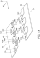
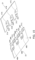
- FIGS. 14 and 15 are perspective views showing a joint structure between a first cover 21 and a second cover 22 according to a modified example.
- the plurality of first protrusions 37A to 37C and the plurality of second protrusions 47A to 47C may be arranged on the first cover 21. That is, the plurality of first protrusions 37A to 37C may be provided on the first outer plate portions 31A to 31C, and the plurality of second protrusions 47A to 47C may be provided on the first inner plate portions 32A to 32C.
- the plurality of first holes 48A to 48C and the plurality of second holes 38A to 38C may be arranged in the second cover 22. That is, the plurality of first holes 48A to 48C may be provided in the second inner plate portions 42A to 42C, and the plurality of second holes 38A to 38C may be provided in the second outer plate portions 41A to 41C.
Landscapes
- Engineering & Computer Science (AREA)
- Mechanical Engineering (AREA)
- Connection Of Plates (AREA)
Abstract
Description
- The present invention relates to a joint structure for a vehicle body cover in a straddled vehicle.
- Some straddled vehicles are equipped with a vehicle body cover. The vehicle body cover is divided into a plurality of covers, which are joined to each other. For example, the motorcycle disclosed in
Japanese Utility Model Publication No. H6-15791 - A straddled vehicle banks left and right while driving. When the vehicle banks to the left and when the vehicle banks to the right, the force that deforms the vehicle body cover acts in different directions. Therefore, the vehicle body cover for the straddled vehicle is required to have high joint strength in various directions. However, in a joint structure such as the above-mentioned straddled vehicle in which the hooks are locked in the locking holes, even if the joint strength in one direction is high, the joint strength in other directions is low.
- Furthermore, in order to increase the joint strength of the vehicle body cover, it is conceivable to firmly fasten a plurality of covers to each other using fastening members such as rivets or bolts. However, in this case, the rigidity of the fastening portion of the vehicle body cover is too high, making it difficult for the fastening portion to follow the deformation of the vehicle body cover.
- An object of the present invention is to provide flexibility of the vehicle body cover and to obtain high joint strength in different directions in a joint structure of a vehicle body cover in a straddled vehicle.
One aspect of the present invention is a joint structure for a vehicle body cover in a straddled vehicle. The vehicle body cover includes a first cover and a second cover. The joint structure includes a plurality of first inner plate portions, a plurality of second inner plate portions, a plurality of first outer plate portions, a plurality of second outer plate portions, a plurality of first protrusions, and a plurality of first holes, a plurality of second protrusions, and a plurality of second holes. The plurality of first inner plate portions are arranged along a seam between the first cover and the second cover. The plurality of first inner plate portions are provided on the first cover. The plurality of second inner plate portions are arranged along the seam. The plurality of second inner plate portions are provided on the second cover. The plurality of first outer plate portions are arranged along the seam. The plurality of first outer plate portions are provided on the first cover. The plurality of first outer plate portions respectively overlap the plurality of second inner plate portions from an outside in a thickness direction of the first cover and the second cover. The plurality of second outer plate portions are arranged along the seam. The plurality of second outer plate portions are provided on the second cover. The plurality of second outer plate portions respectively overlap the plurality of first inner plate portions from the outside in the thickness direction. The plurality of first protrusions are provided on one of the plurality of first outer plate portions and the plurality of second inner plate portions respectively. The plurality of first holes are provided in the other of the plurality of first outer plate portions and the plurality of second inner plate portions respectively. The plurality of first holes are respectively engaged with the plurality of first protrusions. The plurality of second protrusions are provided on one of the plurality of first inner plate portions and the plurality of second outer plate portions respectively. The plurality of second holes are provided in the other of the plurality of first inner plate portions and the plurality of second outer plate portions respectively. The plurality of second holes are respectively engaged with the plurality of second protrusions. - In the straddled vehicle according to the present aspect, when a force is applied to the vehicle body cover in a direction in which the first protrusion is removed from the first hole, that is, in a direction in which the first outer plate portion is separated from the second inner plate portion, a force with which the first inner plate portion is pressed against the second outer plate portion increases. This increases a force with which the second protrusion locks into the second hole. Conversely, when a force is applied to the vehicle body cover in a direction in which the second protrusion is removed from the second hole, that is, in a direction in which the second outer plate portion is separated from the first inner plate portion, a force with which the second inner plate portion is pressed against the first outer plate portion increases. This increases a force with which the first protrusion locks into the first hole. Therefore, it is possible to obtain high joint strength in different directions while providing the flexibility of the vehicle body cover without using strong fasteners such as rivets or the like.
- The plurality of first protrusions may be provided on the plurality of first outer plate portions respectively. The plurality of first holes may be provided in the plurality of second inner plate portions respectively. The plurality of second protrusions may be provided on the plurality of second outer plate portions respectively. The plurality of second holes may be provided in the plurality of first inner plate portions respectively.
- The plurality of first protrusions and the plurality of second holes may be alternately arranged along the seam in the first cover. The plurality of second protrusions and the plurality of first holes may be alternately arranged along the seam in the second cover. In this case, the first cover and the second cover are difficult to separate from each other while providing the flexibility of the vehicle body cover at the seam.
- The plurality of first outer plate portions and the plurality of second outer plate portions may each have a zigzag shape that meshes with each other in a extending direction in which the seam extends. In this case, high joint strength can be obtained even against deformation of the vehicle body cover in the extending direction of the seam.
- The plurality of first inner plate portions and the plurality of second inner plate portions may each have a zigzag shape that meshes with each other in the extending direction in which the seam extends. In this case, high joint strength can be obtained even against deformation of the vehicle body cover in the extending direction of the seam.
- The plurality of first outer plate portions and the plurality of second outer plate portions may be arranged alternately with each other along the seam. In this case, high joint strength can be obtained even against deformation of the vehicle body cover in the extending direction of the seam.
- The plurality of first outer plate portions and the plurality of second outer plate portions may be arranged flush on an outer surface of the vehicle body cover. In this case, compared to a case where a protrusion is provided on the outer surface of the vehicle body cover, the vehicle body cover is prevented from coming into contact with the road surface when the vehicle travels on a road surface with a step.
- The plurality of first inner plate portions and the plurality of second inner plate portions may be arranged alternately with each other along the seam. In this case, high joint strength can be obtained even against deformation of the vehicle body cover in the extending direction of the seam.
- The plurality of first protrusions may be provided on the plurality of first outer plate portions respectively. The plurality of first holes may be provided in the plurality of second inner plate portions respectively. The plurality of second protrusions may be provided on the plurality of first inner plate portions respectively. The plurality of second holes may be provided in the plurality of second outer plate portions respectively.
- The vehicle body cover may have a curved shape at the seam. In this case, high joint strength can be obtained even for the curved vehicle body cover.
- The vehicle body cover may be divided into the first cover and the second cover in a left-right direction of the straddled vehicle. In this case, when the vehicle banks left or right, a large force is applied that deforms the vehicle body cover, but the joint structure according to the present aspect provides flexibility and high joint strength.
- The straddled vehicle may include a front wheel. The joint structure may be located adjacent to the front wheel. In this case, although the joint structure is exposed to harsh environments such as collisions with stones and the like from the front wheel, the joint structure according to the present aspect provides high joint strength.
- The first cover and the second cover may be an undercover arranged behind the front wheel. In this case, although the joint structure is exposed to harsh environments such as collisions with stones and the like from the front wheel, the joint structure according to the present aspect provides high joint strength.
- The first cover and the second cover may be an inner panel arranged above the front wheel. In this case, although the joint structure is exposed to harsh environments such as collisions with stones and the like from the front wheel, the joint structure according to the present aspect provides high joint strength.
- Another aspect of the present invention is a straddled vehicle, which includes the above-described joint structure.
-
-
FIG. 1 is a side view of a straddled vehicle according to an embodiment. -
FIG. 2 is a front view of the straddled vehicle. -
FIG. 3 is a bottom view of an undercover. -
FIG. 4 is a perspective view of the undercover. -
FIG. 5 is a perspective view of the undercover. -
FIG. 6 is a perspective view showing a joint structure between a first cover and a second cover. -
FIG. 7 is a perspective view showing the joint structure between the first cover and the second cover. -
FIG. 8 is a top view showing the joint structure of the first cover and the second cover. -
FIG. 9 is an exploded perspective view showing the joint structure of the first cover and the second cover. -
FIG. 10 is an exploded perspective view showing the joint structure of the first cover and the second cover. -
FIG. 11 is a sectional view taken along line XI-XI inFIG. 8 . -
FIG. 12 is a sectional view taken along line XII-XII inFIG. 8 . -
FIG. 13 is a bottom view showing an inner panel according to another embodiment. -
FIG. 14 is a perspective view showing a joint structure between a first cover and a second cover according to a modification. -
FIG. 15 is a perspective view showing the joint structure between the first cover and the second cover according to the modification. - Hereinafter, a straddled vehicle according to an embodiment will be described with reference to the drawings.
FIG. 1 is a side view of a straddled vehicle 1 according to an embodiment.FIG. 2 is a front view of the straddled vehicle 1. The straddled vehicle 1 according to the present embodiment is a so-called full cowl type motorcycle. As shown inFIG. 1 , the straddled vehicle 1 includes asteering device 2, afront wheel 3, afuel tank 4, aseat 5, anengine 6, arear wheel 7, arear arm 8, and avehicle body cover 9. In the present embodiment, the front, rear, left, and right directions refer to the front, rear, left, and right directions as viewed from a rider seated on theseat 5. - The
steering device 2 is steered by a rider. Thesteering device 2 includes afront fork 11 and ahandle member 12. Thefront fork 11 rotatably supports thefront wheel 3. Thehandle member 12 is connected to thefront fork 11. As shown inFIG. 2 , thefront fork 11 includes afirst suspension 13 and asecond suspension 14. - The
fuel tank 4 is arranged behind thehandle member 12. Theseat 5 is arranged behind thefuel tank 4. Theengine 6 is arranged between thefront wheel 3 and therear wheel 7. Theengine 6 is arranged below thefuel tank 4. Theengine 6 generates driving force that rotates therear wheel 7. Therear wheel 7 is arranged behind theengine 6. Therear wheel 7 is rotatably supported by therear arm 8. - The
vehicle body cover 9 includes afront cover 17, afirst side cover 18, and asecond side cover 19. Thefront cover 17 is arranged in front of thesteering device 2. Thefirst side cover 18 and thesecond side cover 19 extend rearward from thefront cover 17. Thefirst side cover 18 and thesecond side cover 19 cover thesteering device 2 and theengine 6 from the left and right sides. - The
vehicle body cover 9 includes aninner panel 16 and an undercover 15. Theinner panel 16 is arranged above thefront wheel 3. Theinner panel 16 is arranged close to thefront wheel 3. Theinner panel 16 is arranged inside thefirst side cover 18 and thesecond side cover 19. - The undercover 15 is arranged behind the
front wheel 3. The undercover 15 is arranged close to thefront wheel 3. The undercover 15 is arranged below thefirst side cover 18 and thesecond side cover 19.FIG. 3 is a bottom view of the undercover 15.FIGS. 4 and5 are perspective views of the undercover 15.FIG. 4 shows a bottom surface of the undercover 15.FIG. 5 shows a top surface of the undercover 15. - As shown in
FIGS. 3 to 5 , the undercover 15 includes afirst cover 21 and asecond cover 22. Thefirst cover 21 and thesecond cover 22 are separate bodies from each other. The undercover 15 is divided into thefirst cover 21 and thesecond cover 22 in the left-right direction. Thefirst cover 21 is arranged below thefirst side cover 18. Thefirst cover 21 is connected to thefirst side cover 18. Thesecond cover 22 is arranged below thesecond side cover 19. Thesecond cover 22 is connected to thesecond side cover 19. In the present embodiment, thefirst cover 21 is arranged on the left side, and thesecond cover 22 is arranged on the right side. However, thefirst cover 21 may be arranged on the right side, and thesecond cover 22 may be arranged on the left side. Thefirst cover 21 and thesecond cover 22 are joined to each other. - A joint structure between the
first cover 21 and thesecond cover 22 will be described below.FIGS. 6 and7 are perspective views showing the joint structure between thefirst cover 21 and thesecond cover 22.FIG. 6 shows the top surfaces of thefirst cover 21 and thesecond cover 22.FIG. 7 shows the bottom surfaces of thefirst cover 21 and thesecond cover 22.FIG. 8 is a top view showing the joint structure between thefirst cover 21 and thesecond cover 22.FIGS. 9 and10 are exploded perspective views showing the joint structure of thefirst cover 21 and thesecond cover 22.FIG. 9 shows the top surfaces of thefirst cover 21 and thesecond cover 22.FIG. 10 shows the bottom surfaces of thefirst cover 21 and thesecond cover 22. - Note that in
FIGS. 6 to 10 , only the vicinity of the joint structure between thefirst cover 21 and thesecond cover 22 is illustrated, and other parts are omitted. In the following description, a direction in which a seam between thefirst cover 21 and thesecond cover 22 extends will be referred to as an extending direction Y1. A direction in which thefirst cover 21 and thesecond cover 22 face each other will be referred to as a joining direction X1. In the present embodiment, the extending direction Y1 corresponds to the front-rear direction of the straddled vehicle 1. The joining direction X1 corresponds to the left-right direction of the straddled vehicle 1. Further, a thickness direction Z1 of thefirst cover 21 and thesecond cover 22 corresponds to the vertical direction of the straddled vehicle 1. - As shown in
FIGS. 6 to 10 , thefirst cover 21 includes a firstmain plate portion 30, a plurality of firstouter plate portions 31A to 31C, and a plurality of firstinner plate portions 32A to 32C. The firstmain plate portion 30 has a flat shape. Alternatively, the firstmain plate portion 30 may have a curved shape. The plurality of firstouter plate portions 31A to 31C and the plurality of firstinner plate portions 32A to 32C protrude from the firstmain plate portion 30 in the joining direction X1. The plurality of firstouter plate portions 31A to 31C are arranged in line in the extending direction Y1. The plurality of firstinner plate portions 32A to 32C are arranged in line in the extending direction Y1. The plurality of firstouter plate portions 31A to 31C and the plurality of firstinner plate portions 32A to 32C are alternately arranged in line in the extending direction Y1. The plurality of firstouter plate portions 31A to 31C are located on the outer side than the plurality of firstinner plate portions 32A to 32C in the thickness direction Z1. - Specifically, as shown in
FIG. 7 , the firstouter plate portions 31A to 31C have a tapered shape toward the joining direction X1.FIG. 11 is a sectional view taken along line XI-XI inFIG. 8 . As shown inFIG. 11 , theinner surface 311 of the firstouter plate portion 31A is located on the outer side than theinner surface 301 of the firstmain plate portion 30 in the thickness direction Z1. A steppedportion 303 is provided between theinner surface 311 of the firstouter plate portion 31A and theinner surface 301 of the firstmain plate portion 30. Theouter surface 312 of the firstouter plate portion 31A is flush with theouter surface 302 of the firstmain plate portion 30. The other firstouter plate portions outer plate portion 31A. -
FIG. 12 is a sectional view taken along line XII-XII inFIG. 8 . As shown inFIG. 12 , theinner surface 321 of the firstinner plate portion 32A is located on the inner side than theinner surface 301 of the firstmain plate portion 30 in the thickness direction Z1. A steppedportion 304 is provided between theinner surface 321 of the firstinner plate portion 32A and theinner surface 301 of the firstmain plate portion 30. Theouter surface 322 of the firstinner plate portion 32A is located on the inner side than theouter surface 302 of the firstmain plate portion 30 in the thickness direction Z1. - As shown in
FIG. 8 , the firstinner plate portion 32A includes a firstwide portion 33A and a firstnarrow portion 34A. The firstnarrow portion 34A protrudes from the firstwide portion 33A in the joining direction X1. The firstnarrow portion 34A is smaller than the firstwide portion 33A in the extending direction Y1. Therefore, a pair offirst corner portions narrow portion 34A and the firstwide portion 33A. The pair offirst corner portions narrow portion 34A in one direction and the other in the extending direction Y1, respectively. - The other first
inner plate portions inner plate portion 32A. The firstinner plate portion 32B includes a firstwide portion 33B and a firstnarrow portion 34B. A pair offirst corner portions wide portion 33B and the firstnarrow portion 34B. The firstinner plate portion 32C includes a firstwide portion 33C and a firstnarrow portion 34C. A pair offirst corner portions wide portion 33C and the firstnarrow portion 34C. - The
second cover 22 includes a secondmain plate portion 40, a plurality of secondouter plate portions 41A to 41C, and a plurality of secondinner plate portions 42A to 42C. The secondmain plate portion 40 has a flat shape. Alternatively, the secondmain plate portion 40 may have a curved shape. The plurality of secondouter plate portions 41A to 41C and the plurality of secondinner plate portions 42A to 42C protrude from the secondmain plate portion 40 in the joining direction X1. The plurality of secondouter plate portions 41A to 41C are arranged in line in the extending direction Y1. The plurality of secondinner plate portions 42A to 42C are arranged in line in the extending direction Y1. The plurality of secondouter plate portions 41A to 41C and the plurality of secondinner plate portions 42A to 42C are alternately arranged in line in the extending direction Y1. The plurality of secondouter plate portions 41A to 41C are located on the outer side than the plurality of secondinner plate portions 42A to 42C in the thickness direction Z1. - The plurality of second
outer plate portions 41A to 41C have the same shape as the plurality of firstouter plate portions 31A to 31C. As shown inFIG. 12 , theinner surface 411 of the secondouter plate portion 41A is located on the outer side than theinner surface 401 of the secondmain plate portion 40 in the thickness direction Z1. A steppedportion 403 is provided between theinner surface 411 of the secondouter plate portion 41A and theinner surface 401 of the secondmain plate portion 40. Theouter surface 412 of the secondouter plate portion 41A is flush with theouter surface 402 of the secondmain plate portion 40. The other secondouter plate portions outer plate portion 41A. - The plurality of second
inner plate portions 42A to 42C have the same shape as the plurality of firstinner plate portions 32A to 32C. As shown inFIG. 11 , theinner surface 421 of the secondinner plate portion 42A is located on the inner side than theinner surface 401 of the secondmain plate portion 40 in the thickness direction Z1. A steppedportion 404 is provided between theinner surface 421 of the secondinner plate portion 42A and theinner surface 401 of the secondmain plate portion 40. Theouter surface 422 of the secondinner plate portion 42A is located on the inner side than theouter surface 402 of the secondmain plate portion 40 in the thickness direction Z1. - As shown in
FIG. 8 , the secondinner plate portion 42A includes a secondwide portion 43A and a secondnarrow portion 44A. A pair ofsecond corner portions narrow portion 44A and the secondwide portion 43A. The secondwide portion 43A, the secondnarrow portion 44A, and the pair ofsecond corner portions wide portion 33A, the firstnarrow portion 34A, and the pair offirst corner portions inner plate portions inner plate portion 42A. The secondinner plate portion 42B includes a secondwide portion 43B and a secondnarrow portion 44B. A pair ofsecond corner portions 45B and 46B are provided between the secondwide portion 43B and the secondnarrow portion 44B. The secondinner plate portion 42C includes a secondwide portion 43C and a secondnarrow portion 44C. A pair ofsecond corner portions 45C and 46C are provided between the secondwide portion 43C and the secondnarrow portion 44C. - The plurality of first
outer plate portions 31A to 31C overlap with the plurality of secondinner plate portions 42A to 42C from the outside in the thickness direction Z1, respectively. The plurality of secondouter plate portions 41A to 41C overlap with the plurality of firstinner plate portions 32A to 32C from the outside in the thickness direction Z1, respectively. As shown inFIG. 7 , the plurality of firstouter plate portions 31A to 31C and the plurality of secondouter plate portions 41A to 41C are arranged alternately along the seam. The plurality of firstouter plate portions 31A to 31C and the plurality of secondouter plate portions 41A to 41C each have a zigzag shape that meshes with each other in the extending direction Y1 in which the seam extends. The plurality of firstouter plate portions 31A to 31C and the plurality of secondouter plate portions 41A to 41C are arranged flush on the outer surface of the undercover 15. - As shown in
FIGS. 6 and8 , the plurality of firstinner plate portions 32A to 32C and the plurality of secondinner plate portions 42A to 42C are arranged alternately along the seam. The plurality of firstinner plate portions 32A to 32C and the plurality of secondinner plate portions 42A to 42C each have a zigzag shape that meshes with each other in the extending direction Y1 in which the seam extends. - Specifically, as shown in
FIG. 8 , the plurality of firstwide portions 33A to 33C and the plurality of secondnarrow portions 44A to 44C are alternately arranged in line in the extending direction Y1. The plurality of secondwide portions 43A to 43C and the plurality of firstnarrow portions 34A to 34C are alternately arranged in line in the extending direction Y1. The plurality offirst corner portions second corner portions first corner portions second corner portions - A plurality of
first protrusions 37A to 37C are provided on each of the plurality of firstouter plate portions 31A to 31C, respectively. The plurality offirst protrusions 37A to 37C are arranged along the seam between thefirst cover 21 and thesecond cover 22. The plurality offirst protrusions 37A to 37C are arranged in line in the extending direction Y1. The plurality offirst protrusions 37A to 37C each protrude inward in the thickness direction Z1 from the inner surface of the plurality of firstouter plate portions 31A. - As shown in
FIG. 11 , thefirst protrusion 37A includes afirst end surface 371 and a firstinclined surface 372. Thefirst end surface 371 extends inward in the thickness direction Z1 from theinner surface 311 of the firstouter plate portion 31A. The firstinclined surface 372 is inclined with respect to theinner surface 311 of the firstouter plate portion 31A. The firstinclined surface 372 is inclined outward in the thickness direction Z1 with respect to the joining direction X1. The otherfirst protrusions first protrusion 37A. - A plurality of
second holes 38A to 38C are provided in the plurality of firstinner plate portions 32A to 32C, respectively. The plurality ofsecond holes 38A to 38C each penetrate the plurality of firstinner plate portions 32A to 32C in the thickness direction Z1. Specifically, the plurality ofsecond holes 38A to 38C are provided in the plurality of firstwide portions 33A to 33C, respectively. The plurality ofsecond holes 38A to 38C are arranged along the seam. The plurality ofsecond holes 38A to 38C are arranged in line in the extending direction Y1. The plurality offirst protrusions 37A to 37C and the plurality ofsecond holes 38A to 38C are arranged alternately in the extending direction Y1 in thefirst cover 21. The plurality offirst protrusions 37A to 37C are arranged closer to thesecond cover 22 than the plurality ofsecond holes 38A to 38C in the joining direction X1. - A plurality of
second protrusions 47A to 47C are provided on the plurality of secondouter plate portions 41A to 41C, respectively. The plurality ofsecond protrusions 47A to 47C are arranged along the seam between thefirst cover 21 and thesecond cover 22. The plurality ofsecond protrusions 47A to 47C are arranged in line in the extending direction Y1. The plurality ofsecond protrusions 47A to 47C each protrude inward in the thickness direction Z1 from the inner surface of the plurality of secondouter plate portions 41A. - The plurality of
second protrusions 47A to 47C have the same shape as the plurality offirst protrusions 37A to 37C. As shown inFIG. 12 , thesecond protrusion 47A includes asecond end surface 471 and a secondinclined surface 472. Thesecond end surface 471 extends inward in the thickness direction Z1 from theinner surface 411 of the secondouter plate portion 41A. The secondinclined surface 472 is inclined with respect to theinner surface 411 of the secondouter plate portion 41A. The secondinclined surface 472 is inclined outward in the thickness direction Z1 with respect to the joining direction X1. The othersecond protrusions second protrusion 47A. - A plurality of
first holes 48A to 48C are provided in the plurality of secondinner plate portions 42A to 42C, respectively. The plurality offirst holes 48A to 48C respectively penetrate the plurality of secondinner plate portions 42A to 42C in the thickness direction Z1. Specifically, the plurality offirst holes 48A to 48C are provided in the plurality of secondwide portions 43A to 43C, respectively. The plurality offirst holes 48A to 48C are arranged along the seam. The plurality offirst holes 48A to 48C are arranged in line in the extending direction Y1. The plurality ofsecond protrusions 47A to 47C and the plurality offirst holes 48A to 48C are arranged alternately in the extending direction Y1 in thesecond cover 22. The plurality ofsecond protrusions 47A to 47C are arranged closer to thefirst cover 21 than the plurality offirst holes 48A to 48C in the joining direction X1. - The plurality of
first protrusions 37A to 37C are arranged within the plurality offirst holes 48A to 48C, respectively. The plurality offirst protrusions 37A to 37C are engaged with the plurality offirst holes 48A to 48C. The plurality ofsecond protrusions 47A to 47C are arranged within the plurality ofsecond holes 38A to 38C, respectively. The plurality ofsecond protrusions 47A to 47C are respectively engaged with the plurality ofsecond holes 38A to 38C. - In the straddled vehicle 1 according to the present embodiment described above, when a force is applied to the undercover 15 in a direction in which the plurality of
first protrusions 37A to 37C are removed from the plurality offirst holes 48A to 48C, that is, in a direction in which the firstouter plate portions 31A to 31C move away from the secondinner plate portions 42A to 42C, a force pressing the firstinner plate portions 32A to 32C against the secondouter plate portions 41A to 41C increases. This increases a force with which thesecond protrusions 47A to 47C lock into thesecond holes 38A to 38C. Conversely, when a force is applied to the undercover 15 in a direction in which the plurality ofsecond protrusions 47A to 47C are removed from the plurality of thesecond holes 38A to 38C, that is, in a direction in which the secondouter plate portions 41A to 41C move away from the firstinner plate portions 32A to 32C, a force with which the secondinner plate portions 42A to 42C are pressed against the firstouter plate portions 31A to 31C increases. This increases a force with which thefirst protrusions 37A to 37C engage thefirst holes 48A to 48C. Therefore, high joint strength in mutually different directions can be obtained while providing the flexibility of the undercover 15 without using strong fastener such as rivets or the like. - Although one embodiment of the present invention has been described above, the present invention is not limited to the above embodiment, and various changes can be made without departing from the gist of the invention.
- The straddled vehicle 1 is not limited to a full cowl type motorcycle, but may be a half cowl type or a naked type motorcycle. Alternatively, the straddled vehicle 1 may be another type of vehicle such as a moped or a scooter.
- The
first cover 21 and thesecond cover 22 are not limited to the undercover 15 but may be other parts of thevehicle body cover 9. For example, thefirst cover 21 and thesecond cover 22 may be theinner panel 16. As shown inFIG. 13 , in theinner panel 16, thefirst cover 21 and thesecond cover 22 may be joined to each other by the above-described joint structure. - The shapes or arrangement of the
first cover 21 and thesecond cover 22 are not limited to those of the above embodiments, and may be changed. Thefirst cover 21 and thesecond cover 22 are not limited to a flat shape, but may have a curved shape at the seam. Thefirst cover 21 and thesecond cover 22 may be separate bodies from each other not only in the left-right direction of the straddled vehicle 1 but also in the vertical direction or the front-rear direction. - The
first cover 21 and thesecond cover 22 may be coupled by a fastening member such as a rivet. Even in that case, according to the joint structure according to the present embodiment, by reducing the number of fastening members, high joining strength in mutually different directions can be obtained while providing the flexibility of the undercover 15. - The shapes or arrangements of the first
outer plate portions 31A to 31C, the firstinner plate portions 32A to 32C, the secondouter plate portions 41A to 41C, and the secondinner plate portions 42A to 42C are not limited to those of the above embodiments, and may be changed. For example, the firstinner plate portions 32A to 32C and the secondinner plate portions 42A to 42C may have a straight shape similar to the firstouter plate portions 31A to 31C and the secondouter plate portions 41A to 41C of the above embodiment. Alternatively, the firstouter plate portions 31A to 31C and the secondouter plate portions 41A to 41C have a bent shape with corner portions similar to the firstinner plate portions 32A to 32C and the secondinner plate portions 42A to 42C of the above embodiment. - The shape or arrangement of the plurality of
first protrusions 37A to 37C, the plurality ofsecond protrusions 47A to 47C, the plurality offirst holes 48A to 48C, and the plurality ofsecond holes 38A to 38C are not limited to those of the above embodiments, and may be changed. For example,FIGS. 14 and15 are perspective views showing a joint structure between afirst cover 21 and asecond cover 22 according to a modified example. - As shown in
FIGS. 14 and15 , the plurality offirst protrusions 37A to 37C and the plurality ofsecond protrusions 47A to 47C may be arranged on thefirst cover 21. That is, the plurality offirst protrusions 37A to 37C may be provided on the firstouter plate portions 31A to 31C, and the plurality ofsecond protrusions 47A to 47C may be provided on the firstinner plate portions 32A to 32C. The plurality offirst holes 48A to 48C and the plurality ofsecond holes 38A to 38C may be arranged in thesecond cover 22. That is, the plurality offirst holes 48A to 48C may be provided in the secondinner plate portions 42A to 42C, and the plurality ofsecond holes 38A to 38C may be provided in the secondouter plate portions 41A to 41C. - 1: Straddled vehicle, 3: Front wheel, 9: Vehicle body cover, 15: Undercover, 16: Inner panel, 21: First cover, 22: Second cover, 31A-31C: First outer plate portion, 32A-32C First inner plate portion, 37A-37C: First protrusion, 38A-38C: Second hole, 41A-41B: Second outer plate portion, 42A-42C: Second inner plate portion, 47A-47C: Second protrusion, 48A-48C: First hole
Claims (15)
- A joint structure for a vehicle body cover (9) including a first cover (21) and a second cover (22) in a straddled vehicle (1), the joint structure comprising:a plurality of first inner plate portions (32A, 32B, 32C) arranged along a seam between the first cover (21) and the second cover (22) and provided on the first cover (21);a plurality of second inner plate portions (42A, 42B, 42C) arranged along the seam and provided on the second cover (22);a plurality of first outer plate portions (31A, 31B, 31C) that are arranged along the seam, are provided on the first cover (21), and respectively overlap the plurality of second inner plate portions (42A, 42B, 42C) from an outside in a thickness direction (Z1) of the first cover (21)and the second cover (22);a plurality of second outer plate portions (41A, 41B, 41C) that are arranged along the seam, are provided on the second cover (22), and respectively overlap the plurality of first inner plate portions (32A, 32B, 32C) from the outside in the thickness direction (Z1);a plurality of first protrusions (37A, 37B, 37C) provided on one (31A, 31B, 31C) of the plurality of first outer plate portions (31A, 31B, 31C) and the plurality of second inner plate portions (42A, 42B, 42C), respectively;a plurality of first holes (48A, 48B, 48C) that are provided in the other (42A, 42B, 42C) of the plurality of first outer plate portions (31A, 31B, 31C) and the plurality of second inner plate portions (42A, 42B, 42C), and engage with the plurality of first protrusions (37A, 37B, 37C), respectively;a plurality of second protrusions (47A, 47B, 47C) provided on one (41A, 41B, 41C) of the plurality of first inner plate portions (32A, 32B, 32C) and the plurality of second outer plate portions (41A, 41B, 41C), respectively; anda plurality of second holes (38A, 38B, 38C) that are provided in the other (32A, 32B, 32C) of the plurality of first inner plate portions (32A, 32B, 32C) and the plurality of second outer plate portions (41A, 41B, 41C), and engage with the plurality of second protrusions (47A, 47B, 47C), respectively.
- The joint structure according to claim 1, whereinthe plurality of first protrusions (37A, 37B, 37C) are respectively provided on the plurality of first outer plate portions (31A, 31B, 31C),the plurality of first holes (48A, 48B, 48C) are respectively provided in the plurality of second inner plate portions (42A, 42B, 42C),the plurality of second protrusions (47A, 47B, 47C) are respectively provided on the plurality of second outer plate portions (41A, 41B, 41C), andthe plurality of second holes (38A, 38B, 38C) are respectively provided in the plurality of first inner plate portions (32A, 32B, 32C).
- The joint structure according to claim 2, whereinthe plurality of first protrusions (37A, 37B, 37C) and the plurality of second holes (38A, 38B, 38C) are alternately arranged along the seam in the first cover (21), andthe plurality of second protrusions (47A, 47B, 47C) and the plurality of first holes (48A, 48B, 48C) are alternately arranged along the seam in the second cover (22).
- The joint structure according to any one of claims 1 to 3, wherein
the plurality of first outer plate portions (31A, 31B, 31C) and the plurality of second outer plate portions (41A, 41B, 41C) each have a zigzag shape that meshes with each other in an extending direction in which the seam extends. - The joint structure according to any one of claims 1 to 4, wherein
the plurality of first inner plate portions (32A, 32B, 32C) and the plurality of second inner plate portions (42A, 42B, 42C) each have a zigzag shape that meshes with each other in a extending direction in which the seam extends. - The joint structure according to any one of claims 1 to 5, wherein
the plurality of first outer plate portions (31A, 31B, 31C) and the plurality of second outer plate portions (41A, 41B, 41C) are arranged alternately along the seam. - The joint structure according to claim 6, wherein
the plurality of first outer plate portions (31A, 31B, 31C) and the plurality of second outer plate portions (41A, 41B, 41C) are arranged flush on an outer surface of the vehicle body cover (9). - The joint structure according to any one of claims 1 to 7, wherein
the plurality of first inner plate portions (32A, 32B, 32C) and the plurality of second inner plate portions (42A, 42B, 42C) are arranged alternately along the seam. - The joint structure according to claim 1, whereinthe plurality of first protrusions (37A, 37B, 37C) are respectively provided on the plurality of first outer plate portions (31A, 31B, 31C),the plurality of first holes (48A, 48B, 48C) are respectively provided in the plurality of second inner plate portions (42A, 42B, 42C),the plurality of second protrusions (47A, 47B, 47C) are respectively provided on the plurality of first inner plate portions (32A, 32B, 32C), andthe plurality of second holes (38A, 38B, 38C) are respectively provided in the plurality of second outer plate portions (41A, 41B, 41C).
- The joint structure according to any one of claims 1 to 9, wherein
the vehicle body cover (9) has a curved shape at the seam. - The joint structure according to any one of claims 1 to 10, wherein
the vehicle body cover (9) is divided into the first cover (21) and the second cover (22) in a left-right direction of the straddled vehicle (1). - The joint structure according to claim 11, whereinthe straddled vehicle (1) includes a front wheel (3), andthe joint structure is arranged adjacent to the front wheel (3).
- The joint structure according to claim 12, wherein
the first cover (21) and the second cover (22) are an undercover (15) arranged behind the front wheel (3). - The joint structure according to claim 12, wherein
the first cover (21) and the second cover (22) are an inner panel (16) arranged above the front wheel (3). - A straddled vehicle (1) comprising the joint structure according to any one of claims 1 to 14.
Applications Claiming Priority (1)
| Application Number | Priority Date | Filing Date | Title |
|---|---|---|---|
| JP2023114564A JP2025012036A (en) | 2023-07-12 | 2023-07-12 | Joining structure of body cover for saddle-type vehicle |
Publications (2)
| Publication Number | Publication Date |
|---|---|
| EP4491498A1 true EP4491498A1 (en) | 2025-01-15 |
| EP4491498B1 EP4491498B1 (en) | 2025-10-15 |
Family
ID=88978218
Family Applications (1)
| Application Number | Title | Priority Date | Filing Date |
|---|---|---|---|
| EP23212568.2A Active EP4491498B1 (en) | 2023-07-12 | 2023-11-28 | Joint structure for vehicle body cover in straddled vehicle |
Country Status (2)
| Country | Link |
|---|---|
| EP (1) | EP4491498B1 (en) |
| JP (1) | JP2025012036A (en) |
Citations (3)
| Publication number | Priority date | Publication date | Assignee | Title |
|---|---|---|---|---|
| EP0102347B1 (en) * | 1982-09-01 | 1987-04-08 | Steyr-Daimler-Puch Aktiengesellschaft | Frames for two-wheeled vehicles |
| JPH0615791U (en) | 1992-04-06 | 1994-03-01 | 株式会社ジャパンケミックス | Magnetic device for water treatment |
| WO2002055370A1 (en) * | 2001-01-09 | 2002-07-18 | Honda Giken Kogyo Kabushiki Kaisha | Body cover structure for motorcycle |
-
2023
- 2023-07-12 JP JP2023114564A patent/JP2025012036A/en active Pending
- 2023-11-28 EP EP23212568.2A patent/EP4491498B1/en active Active
Patent Citations (3)
| Publication number | Priority date | Publication date | Assignee | Title |
|---|---|---|---|---|
| EP0102347B1 (en) * | 1982-09-01 | 1987-04-08 | Steyr-Daimler-Puch Aktiengesellschaft | Frames for two-wheeled vehicles |
| JPH0615791U (en) | 1992-04-06 | 1994-03-01 | 株式会社ジャパンケミックス | Magnetic device for water treatment |
| WO2002055370A1 (en) * | 2001-01-09 | 2002-07-18 | Honda Giken Kogyo Kabushiki Kaisha | Body cover structure for motorcycle |
Also Published As
| Publication number | Publication date |
|---|---|
| JP2025012036A (en) | 2025-01-24 |
| EP4491498B1 (en) | 2025-10-15 |
Similar Documents
| Publication | Publication Date | Title |
|---|---|---|
| US8029046B2 (en) | Front vehicle body structure | |
| CN102161362B (en) | Saddle-ride type vehicle | |
| EP1920999B1 (en) | Vehicle body structure | |
| US20100072787A1 (en) | Rear vehicle body structure | |
| EP3437968B1 (en) | Reflector mounting structure for saddled vehicles | |
| EP1582421A2 (en) | Roll bar assembly and method for mounting the same | |
| JP2004123092A (en) | Body cover structure of saddle type vehicle | |
| EP4098529A1 (en) | Straddled vehicle | |
| EP4491498B1 (en) | Joint structure for vehicle body cover in straddled vehicle | |
| JP6750097B2 (en) | Body frame structure of saddle type vehicle | |
| EP2902304B1 (en) | Connecting structure of vehicle component parts | |
| US11952046B2 (en) | Vehicle body | |
| EP3081474B1 (en) | Front wheel supporting frame structure of saddle-ride type vehicle | |
| EP3514046A1 (en) | Body frame for two-wheeled motor vehicle | |
| JPH11278339A (en) | Mounting structure of fork cover | |
| CN110914142B (en) | body frame structure | |
| CN110891853B (en) | body frame structure | |
| JP7601921B2 (en) | Saddle type vehicle | |
| JP4506404B2 (en) | Accelerator pedal mounting structure | |
| CN101544183A (en) | Muffler fixing bracket and straddle type vehicle including the same | |
| JP7042721B2 (en) | Mounting structure of exterior members | |
| EP3002192B1 (en) | Straddled vehicle | |
| CN110914141B (en) | body frame structure | |
| CN221794799U (en) | Saddle-type vehicle | |
| EP4424578A1 (en) | Straddled vehicle |
Legal Events
| Date | Code | Title | Description |
|---|---|---|---|
| PUAI | Public reference made under article 153(3) epc to a published international application that has entered the european phase |
Free format text: ORIGINAL CODE: 0009012 |
|
| STAA | Information on the status of an ep patent application or granted ep patent |
Free format text: STATUS: REQUEST FOR EXAMINATION WAS MADE |
|
| 17P | Request for examination filed |
Effective date: 20231128 |
|
| AK | Designated contracting states |
Kind code of ref document: A1 Designated state(s): AL AT BE BG CH CY CZ DE DK EE ES FI FR GB GR HR HU IE IS IT LI LT LU LV MC ME MK MT NL NO PL PT RO RS SE SI SK SM TR |
|
| P01 | Opt-out of the competence of the unified patent court (upc) registered |
Free format text: CASE NUMBER: APP_7048/2025 Effective date: 20250211 |
|
| RIC1 | Information provided on ipc code assigned before grant |
Ipc: B62M 7/00 20100101ALN20250403BHEP Ipc: B62K 11/00 20060101ALN20250403BHEP Ipc: B62J 17/00 20200101AFI20250403BHEP |
|
| GRAP | Despatch of communication of intention to grant a patent |
Free format text: ORIGINAL CODE: EPIDOSNIGR1 |
|
| STAA | Information on the status of an ep patent application or granted ep patent |
Free format text: STATUS: GRANT OF PATENT IS INTENDED |
|
| INTG | Intention to grant announced |
Effective date: 20250508 |
|
| GRAS | Grant fee paid |
Free format text: ORIGINAL CODE: EPIDOSNIGR3 |
|
| GRAA | (expected) grant |
Free format text: ORIGINAL CODE: 0009210 |
|
| STAA | Information on the status of an ep patent application or granted ep patent |
Free format text: STATUS: THE PATENT HAS BEEN GRANTED |
|
| AK | Designated contracting states |
Kind code of ref document: B1 Designated state(s): AL AT BE BG CH CY CZ DE DK EE ES FI FR GB GR HR HU IE IS IT LI LT LU LV MC ME MK MT NL NO PL PT RO RS SE SI SK SM TR |
|
| REG | Reference to a national code |
Ref country code: GB Ref legal event code: FG4D Ref country code: CH Ref legal event code: F10 Free format text: ST27 STATUS EVENT CODE: U-0-0-F10-F00 (AS PROVIDED BY THE NATIONAL OFFICE) Effective date: 20251015 |
|
| REG | Reference to a national code |
Ref country code: DE Ref legal event code: R096 Ref document number: 602023007523 Country of ref document: DE |
|
| REG | Reference to a national code |
Ref country code: IE Ref legal event code: FG4D |
|
| PGFP | Annual fee paid to national office [announced via postgrant information from national office to epo] |
Ref country code: DE Payment date: 20251119 Year of fee payment: 3 |
|
| PGFP | Annual fee paid to national office [announced via postgrant information from national office to epo] |
Ref country code: AT Payment date: 20260113 Year of fee payment: 3 |
|
| PGFP | Annual fee paid to national office [announced via postgrant information from national office to epo] |
Ref country code: IT Payment date: 20251201 Year of fee payment: 3 |
|
| PGFP | Annual fee paid to national office [announced via postgrant information from national office to epo] |
Ref country code: FR Payment date: 20251209 Year of fee payment: 3 |
|
| REG | Reference to a national code |
Ref country code: NL Ref legal event code: MP Effective date: 20251015 |
|
| REG | Reference to a national code |
Ref country code: AT Ref legal event code: MK05 Ref document number: 1846743 Country of ref document: AT Kind code of ref document: T Effective date: 20251015 |
|
| PG25 | Lapsed in a contracting state [announced via postgrant information from national office to epo] |
Ref country code: NL Free format text: LAPSE BECAUSE OF FAILURE TO SUBMIT A TRANSLATION OF THE DESCRIPTION OR TO PAY THE FEE WITHIN THE PRESCRIBED TIME-LIMIT Effective date: 20251015 |
|
| PG25 | Lapsed in a contracting state [announced via postgrant information from national office to epo] |
Ref country code: ES Free format text: LAPSE BECAUSE OF FAILURE TO SUBMIT A TRANSLATION OF THE DESCRIPTION OR TO PAY THE FEE WITHIN THE PRESCRIBED TIME-LIMIT Effective date: 20251015 |
|
| REG | Reference to a national code |
Ref country code: LT Ref legal event code: MG9D |
|
| PG25 | Lapsed in a contracting state [announced via postgrant information from national office to epo] |
Ref country code: NO Free format text: LAPSE BECAUSE OF FAILURE TO SUBMIT A TRANSLATION OF THE DESCRIPTION OR TO PAY THE FEE WITHIN THE PRESCRIBED TIME-LIMIT Effective date: 20260115 |
|
| PG25 | Lapsed in a contracting state [announced via postgrant information from national office to epo] |
Ref country code: FI Free format text: LAPSE BECAUSE OF FAILURE TO SUBMIT A TRANSLATION OF THE DESCRIPTION OR TO PAY THE FEE WITHIN THE PRESCRIBED TIME-LIMIT Effective date: 20251015 Ref country code: AT Free format text: LAPSE BECAUSE OF FAILURE TO SUBMIT A TRANSLATION OF THE DESCRIPTION OR TO PAY THE FEE WITHIN THE PRESCRIBED TIME-LIMIT Effective date: 20251015 Ref country code: HR Free format text: LAPSE BECAUSE OF FAILURE TO SUBMIT A TRANSLATION OF THE DESCRIPTION OR TO PAY THE FEE WITHIN THE PRESCRIBED TIME-LIMIT Effective date: 20251015 |
|
| PG25 | Lapsed in a contracting state [announced via postgrant information from national office to epo] |
Ref country code: RS Free format text: LAPSE BECAUSE OF FAILURE TO SUBMIT A TRANSLATION OF THE DESCRIPTION OR TO PAY THE FEE WITHIN THE PRESCRIBED TIME-LIMIT Effective date: 20260115 |
|
| PG25 | Lapsed in a contracting state [announced via postgrant information from national office to epo] |
Ref country code: IS Free format text: LAPSE BECAUSE OF FAILURE TO SUBMIT A TRANSLATION OF THE DESCRIPTION OR TO PAY THE FEE WITHIN THE PRESCRIBED TIME-LIMIT Effective date: 20260215 |
|
| PG25 | Lapsed in a contracting state [announced via postgrant information from national office to epo] |
Ref country code: PT Free format text: LAPSE BECAUSE OF FAILURE TO SUBMIT A TRANSLATION OF THE DESCRIPTION OR TO PAY THE FEE WITHIN THE PRESCRIBED TIME-LIMIT Effective date: 20260216 |
|
| PG25 | Lapsed in a contracting state [announced via postgrant information from national office to epo] |
Ref country code: PL Free format text: LAPSE BECAUSE OF FAILURE TO SUBMIT A TRANSLATION OF THE DESCRIPTION OR TO PAY THE FEE WITHIN THE PRESCRIBED TIME-LIMIT Effective date: 20251015 |
|
| PG25 | Lapsed in a contracting state [announced via postgrant information from national office to epo] |
Ref country code: LV Free format text: LAPSE BECAUSE OF FAILURE TO SUBMIT A TRANSLATION OF THE DESCRIPTION OR TO PAY THE FEE WITHIN THE PRESCRIBED TIME-LIMIT Effective date: 20251015 |
|
| PG25 | Lapsed in a contracting state [announced via postgrant information from national office to epo] |
Ref country code: BG Free format text: LAPSE BECAUSE OF FAILURE TO SUBMIT A TRANSLATION OF THE DESCRIPTION OR TO PAY THE FEE WITHIN THE PRESCRIBED TIME-LIMIT Effective date: 20251015 |
|
| PG25 | Lapsed in a contracting state [announced via postgrant information from national office to epo] |
Ref country code: RO Free format text: LAPSE BECAUSE OF FAILURE TO SUBMIT A TRANSLATION OF THE DESCRIPTION OR TO PAY THE FEE WITHIN THE PRESCRIBED TIME-LIMIT Effective date: 20251015 |
|
| PG25 | Lapsed in a contracting state [announced via postgrant information from national office to epo] |
Ref country code: LT Free format text: LAPSE BECAUSE OF FAILURE TO SUBMIT A TRANSLATION OF THE DESCRIPTION OR TO PAY THE FEE WITHIN THE PRESCRIBED TIME-LIMIT Effective date: 20251015 |
|
| PG25 | Lapsed in a contracting state [announced via postgrant information from national office to epo] |
Ref country code: SM Free format text: LAPSE BECAUSE OF FAILURE TO SUBMIT A TRANSLATION OF THE DESCRIPTION OR TO PAY THE FEE WITHIN THE PRESCRIBED TIME-LIMIT Effective date: 20251015 |
|
| PG25 | Lapsed in a contracting state [announced via postgrant information from national office to epo] |
Ref country code: MC Free format text: LAPSE BECAUSE OF FAILURE TO SUBMIT A TRANSLATION OF THE DESCRIPTION OR TO PAY THE FEE WITHIN THE PRESCRIBED TIME-LIMIT Effective date: 20251015 |
|
| PG25 | Lapsed in a contracting state [announced via postgrant information from national office to epo] |
Ref country code: DK Free format text: LAPSE BECAUSE OF FAILURE TO SUBMIT A TRANSLATION OF THE DESCRIPTION OR TO PAY THE FEE WITHIN THE PRESCRIBED TIME-LIMIT Effective date: 20251015 |
|
| PG25 | Lapsed in a contracting state [announced via postgrant information from national office to epo] |
Ref country code: LU Free format text: LAPSE BECAUSE OF NON-PAYMENT OF DUE FEES Effective date: 20251128 |
|
| PG25 | Lapsed in a contracting state [announced via postgrant information from national office to epo] |
Ref country code: EE Free format text: LAPSE BECAUSE OF FAILURE TO SUBMIT A TRANSLATION OF THE DESCRIPTION OR TO PAY THE FEE WITHIN THE PRESCRIBED TIME-LIMIT Effective date: 20251015 |
|
| PG25 | Lapsed in a contracting state [announced via postgrant information from national office to epo] |
Ref country code: CZ Free format text: LAPSE BECAUSE OF FAILURE TO SUBMIT A TRANSLATION OF THE DESCRIPTION OR TO PAY THE FEE WITHIN THE PRESCRIBED TIME-LIMIT Effective date: 20251015 |
|
| PG25 | Lapsed in a contracting state [announced via postgrant information from national office to epo] |
Ref country code: SK Free format text: LAPSE BECAUSE OF FAILURE TO SUBMIT A TRANSLATION OF THE DESCRIPTION OR TO PAY THE FEE WITHIN THE PRESCRIBED TIME-LIMIT Effective date: 20251015 |
|
| PG25 | Lapsed in a contracting state [announced via postgrant information from national office to epo] |
Ref country code: SE Free format text: LAPSE BECAUSE OF FAILURE TO SUBMIT A TRANSLATION OF THE DESCRIPTION OR TO PAY THE FEE WITHIN THE PRESCRIBED TIME-LIMIT Effective date: 20251015 |