EP4491434A1 - Electric power supplying module - Google Patents
Electric power supplying module Download PDFInfo
- Publication number
- EP4491434A1 EP4491434A1 EP24182277.4A EP24182277A EP4491434A1 EP 4491434 A1 EP4491434 A1 EP 4491434A1 EP 24182277 A EP24182277 A EP 24182277A EP 4491434 A1 EP4491434 A1 EP 4491434A1
- Authority
- EP
- European Patent Office
- Prior art keywords
- power
- vehicle
- connector
- voltage
- battery
- Prior art date
- Legal status (The legal status is an assumption and is not a legal conclusion. Google has not performed a legal analysis and makes no representation as to the accuracy of the status listed.)
- Pending
Links
Images





Classifications
-
- B—PERFORMING OPERATIONS; TRANSPORTING
- B60—VEHICLES IN GENERAL
- B60L—PROPULSION OF ELECTRICALLY-PROPELLED VEHICLES; SUPPLYING ELECTRIC POWER FOR AUXILIARY EQUIPMENT OF ELECTRICALLY-PROPELLED VEHICLES; ELECTRODYNAMIC BRAKE SYSTEMS FOR VEHICLES IN GENERAL; MAGNETIC SUSPENSION OR LEVITATION FOR VEHICLES; MONITORING OPERATING VARIABLES OF ELECTRICALLY-PROPELLED VEHICLES; ELECTRIC SAFETY DEVICES FOR ELECTRICALLY-PROPELLED VEHICLES
- B60L58/00—Methods or circuit arrangements for monitoring or controlling batteries or fuel cells, specially adapted for electric vehicles
- B60L58/10—Methods or circuit arrangements for monitoring or controlling batteries or fuel cells, specially adapted for electric vehicles for monitoring or controlling batteries
-
- B—PERFORMING OPERATIONS; TRANSPORTING
- B60—VEHICLES IN GENERAL
- B60K—ARRANGEMENT OR MOUNTING OF PROPULSION UNITS OR OF TRANSMISSIONS IN VEHICLES; ARRANGEMENT OR MOUNTING OF PLURAL DIVERSE PRIME-MOVERS IN VEHICLES; AUXILIARY DRIVES FOR VEHICLES; INSTRUMENTATION OR DASHBOARDS FOR VEHICLES; ARRANGEMENTS IN CONNECTION WITH COOLING, AIR INTAKE, GAS EXHAUST OR FUEL SUPPLY OF PROPULSION UNITS IN VEHICLES
- B60K1/00—Arrangement or mounting of electrical propulsion units
- B60K1/04—Arrangement or mounting of electrical propulsion units of the electric storage means for propulsion
-
- B—PERFORMING OPERATIONS; TRANSPORTING
- B60—VEHICLES IN GENERAL
- B60L—PROPULSION OF ELECTRICALLY-PROPELLED VEHICLES; SUPPLYING ELECTRIC POWER FOR AUXILIARY EQUIPMENT OF ELECTRICALLY-PROPELLED VEHICLES; ELECTRODYNAMIC BRAKE SYSTEMS FOR VEHICLES IN GENERAL; MAGNETIC SUSPENSION OR LEVITATION FOR VEHICLES; MONITORING OPERATING VARIABLES OF ELECTRICALLY-PROPELLED VEHICLES; ELECTRIC SAFETY DEVICES FOR ELECTRICALLY-PROPELLED VEHICLES
- B60L1/00—Supplying electric power to auxiliary equipment of vehicles
-
- B—PERFORMING OPERATIONS; TRANSPORTING
- B60—VEHICLES IN GENERAL
- B60L—PROPULSION OF ELECTRICALLY-PROPELLED VEHICLES; SUPPLYING ELECTRIC POWER FOR AUXILIARY EQUIPMENT OF ELECTRICALLY-PROPELLED VEHICLES; ELECTRODYNAMIC BRAKE SYSTEMS FOR VEHICLES IN GENERAL; MAGNETIC SUSPENSION OR LEVITATION FOR VEHICLES; MONITORING OPERATING VARIABLES OF ELECTRICALLY-PROPELLED VEHICLES; ELECTRIC SAFETY DEVICES FOR ELECTRICALLY-PROPELLED VEHICLES
- B60L1/00—Supplying electric power to auxiliary equipment of vehicles
- B60L1/02—Supplying electric power to auxiliary equipment of vehicles to electric heating circuits
-
- B—PERFORMING OPERATIONS; TRANSPORTING
- B60—VEHICLES IN GENERAL
- B60L—PROPULSION OF ELECTRICALLY-PROPELLED VEHICLES; SUPPLYING ELECTRIC POWER FOR AUXILIARY EQUIPMENT OF ELECTRICALLY-PROPELLED VEHICLES; ELECTRODYNAMIC BRAKE SYSTEMS FOR VEHICLES IN GENERAL; MAGNETIC SUSPENSION OR LEVITATION FOR VEHICLES; MONITORING OPERATING VARIABLES OF ELECTRICALLY-PROPELLED VEHICLES; ELECTRIC SAFETY DEVICES FOR ELECTRICALLY-PROPELLED VEHICLES
- B60L1/00—Supplying electric power to auxiliary equipment of vehicles
- B60L1/14—Supplying electric power to auxiliary equipment of vehicles to electric lighting circuits
-
- B—PERFORMING OPERATIONS; TRANSPORTING
- B60—VEHICLES IN GENERAL
- B60L—PROPULSION OF ELECTRICALLY-PROPELLED VEHICLES; SUPPLYING ELECTRIC POWER FOR AUXILIARY EQUIPMENT OF ELECTRICALLY-PROPELLED VEHICLES; ELECTRODYNAMIC BRAKE SYSTEMS FOR VEHICLES IN GENERAL; MAGNETIC SUSPENSION OR LEVITATION FOR VEHICLES; MONITORING OPERATING VARIABLES OF ELECTRICALLY-PROPELLED VEHICLES; ELECTRIC SAFETY DEVICES FOR ELECTRICALLY-PROPELLED VEHICLES
- B60L15/00—Methods, circuits, or devices for controlling the traction-motor speed of electrically-propelled vehicles
- B60L15/007—Physical arrangements or structures of drive train converters specially adapted for the propulsion motors of electric vehicles
-
- B—PERFORMING OPERATIONS; TRANSPORTING
- B60—VEHICLES IN GENERAL
- B60L—PROPULSION OF ELECTRICALLY-PROPELLED VEHICLES; SUPPLYING ELECTRIC POWER FOR AUXILIARY EQUIPMENT OF ELECTRICALLY-PROPELLED VEHICLES; ELECTRODYNAMIC BRAKE SYSTEMS FOR VEHICLES IN GENERAL; MAGNETIC SUSPENSION OR LEVITATION FOR VEHICLES; MONITORING OPERATING VARIABLES OF ELECTRICALLY-PROPELLED VEHICLES; ELECTRIC SAFETY DEVICES FOR ELECTRICALLY-PROPELLED VEHICLES
- B60L50/00—Electric propulsion with power supplied within the vehicle
- B60L50/50—Electric propulsion with power supplied within the vehicle using propulsion power supplied by batteries or fuel cells
- B60L50/60—Electric propulsion with power supplied within the vehicle using propulsion power supplied by batteries or fuel cells using power supplied by batteries
- B60L50/66—Arrangements of batteries
-
- B—PERFORMING OPERATIONS; TRANSPORTING
- B60—VEHICLES IN GENERAL
- B60L—PROPULSION OF ELECTRICALLY-PROPELLED VEHICLES; SUPPLYING ELECTRIC POWER FOR AUXILIARY EQUIPMENT OF ELECTRICALLY-PROPELLED VEHICLES; ELECTRODYNAMIC BRAKE SYSTEMS FOR VEHICLES IN GENERAL; MAGNETIC SUSPENSION OR LEVITATION FOR VEHICLES; MONITORING OPERATING VARIABLES OF ELECTRICALLY-PROPELLED VEHICLES; ELECTRIC SAFETY DEVICES FOR ELECTRICALLY-PROPELLED VEHICLES
- B60L58/00—Methods or circuit arrangements for monitoring or controlling batteries or fuel cells, specially adapted for electric vehicles
- B60L58/10—Methods or circuit arrangements for monitoring or controlling batteries or fuel cells, specially adapted for electric vehicles for monitoring or controlling batteries
- B60L58/18—Methods or circuit arrangements for monitoring or controlling batteries or fuel cells, specially adapted for electric vehicles for monitoring or controlling batteries of two or more battery modules
- B60L58/20—Methods or circuit arrangements for monitoring or controlling batteries or fuel cells, specially adapted for electric vehicles for monitoring or controlling batteries of two or more battery modules having different nominal voltages
-
- B—PERFORMING OPERATIONS; TRANSPORTING
- B60—VEHICLES IN GENERAL
- B60R—VEHICLES, VEHICLE FITTINGS, OR VEHICLE PARTS, NOT OTHERWISE PROVIDED FOR
- B60R16/00—Electric or fluid circuits specially adapted for vehicles and not otherwise provided for; Arrangement of elements of electric or fluid circuits specially adapted for vehicles and not otherwise provided for
- B60R16/02—Electric or fluid circuits specially adapted for vehicles and not otherwise provided for; Arrangement of elements of electric or fluid circuits specially adapted for vehicles and not otherwise provided for electric constitutive elements
- B60R16/0207—Wire harnesses
-
- B—PERFORMING OPERATIONS; TRANSPORTING
- B60—VEHICLES IN GENERAL
- B60R—VEHICLES, VEHICLE FITTINGS, OR VEHICLE PARTS, NOT OTHERWISE PROVIDED FOR
- B60R16/00—Electric or fluid circuits specially adapted for vehicles and not otherwise provided for; Arrangement of elements of electric or fluid circuits specially adapted for vehicles and not otherwise provided for
- B60R16/02—Electric or fluid circuits specially adapted for vehicles and not otherwise provided for; Arrangement of elements of electric or fluid circuits specially adapted for vehicles and not otherwise provided for electric constitutive elements
- B60R16/03—Electric or fluid circuits specially adapted for vehicles and not otherwise provided for; Arrangement of elements of electric or fluid circuits specially adapted for vehicles and not otherwise provided for electric constitutive elements for supply of electrical power to vehicle subsystems or for
-
- B—PERFORMING OPERATIONS; TRANSPORTING
- B60—VEHICLES IN GENERAL
- B60K—ARRANGEMENT OR MOUNTING OF PROPULSION UNITS OR OF TRANSMISSIONS IN VEHICLES; ARRANGEMENT OR MOUNTING OF PLURAL DIVERSE PRIME-MOVERS IN VEHICLES; AUXILIARY DRIVES FOR VEHICLES; INSTRUMENTATION OR DASHBOARDS FOR VEHICLES; ARRANGEMENTS IN CONNECTION WITH COOLING, AIR INTAKE, GAS EXHAUST OR FUEL SUPPLY OF PROPULSION UNITS IN VEHICLES
- B60K1/00—Arrangement or mounting of electrical propulsion units
- B60K1/04—Arrangement or mounting of electrical propulsion units of the electric storage means for propulsion
- B60K2001/0405—Arrangement or mounting of electrical propulsion units of the electric storage means for propulsion characterised by their position
- B60K2001/0438—Arrangement under the floor
-
- B—PERFORMING OPERATIONS; TRANSPORTING
- B60—VEHICLES IN GENERAL
- B60L—PROPULSION OF ELECTRICALLY-PROPELLED VEHICLES; SUPPLYING ELECTRIC POWER FOR AUXILIARY EQUIPMENT OF ELECTRICALLY-PROPELLED VEHICLES; ELECTRODYNAMIC BRAKE SYSTEMS FOR VEHICLES IN GENERAL; MAGNETIC SUSPENSION OR LEVITATION FOR VEHICLES; MONITORING OPERATING VARIABLES OF ELECTRICALLY-PROPELLED VEHICLES; ELECTRIC SAFETY DEVICES FOR ELECTRICALLY-PROPELLED VEHICLES
- B60L2210/00—Converter types
- B60L2210/10—DC to DC converters
-
- B—PERFORMING OPERATIONS; TRANSPORTING
- B60—VEHICLES IN GENERAL
- B60L—PROPULSION OF ELECTRICALLY-PROPELLED VEHICLES; SUPPLYING ELECTRIC POWER FOR AUXILIARY EQUIPMENT OF ELECTRICALLY-PROPELLED VEHICLES; ELECTRODYNAMIC BRAKE SYSTEMS FOR VEHICLES IN GENERAL; MAGNETIC SUSPENSION OR LEVITATION FOR VEHICLES; MONITORING OPERATING VARIABLES OF ELECTRICALLY-PROPELLED VEHICLES; ELECTRIC SAFETY DEVICES FOR ELECTRICALLY-PROPELLED VEHICLES
- B60L2210/00—Converter types
- B60L2210/40—DC to AC converters
-
- B—PERFORMING OPERATIONS; TRANSPORTING
- B60—VEHICLES IN GENERAL
- B60L—PROPULSION OF ELECTRICALLY-PROPELLED VEHICLES; SUPPLYING ELECTRIC POWER FOR AUXILIARY EQUIPMENT OF ELECTRICALLY-PROPELLED VEHICLES; ELECTRODYNAMIC BRAKE SYSTEMS FOR VEHICLES IN GENERAL; MAGNETIC SUSPENSION OR LEVITATION FOR VEHICLES; MONITORING OPERATING VARIABLES OF ELECTRICALLY-PROPELLED VEHICLES; ELECTRIC SAFETY DEVICES FOR ELECTRICALLY-PROPELLED VEHICLES
- B60L2220/00—Electrical machine types; Structures or applications thereof
- B60L2220/40—Electrical machine applications
- B60L2220/42—Electrical machine applications with use of more than one motor
Definitions
- Embodiments of the present invention relate to an electric power supplying module.
- a vehicle power supply system including a battery and an electric junction box is known.
- the power from the battery is distributed to a plurality of loads in a vehicle via the electric junction box disposed in a front section of the vehicle.
- Patent Document 1 Japanese Unexamined Patent Application, First Publication No. 2018-065485
- An embodiment of the present invention provides an electric power supplying module by which the lengths of routing members can be shortened.
- An electric power supplying module includes a module base, a power conversion unit, a first connector, and a second connector.
- the module base is disposed under a floor of a vehicle.
- the power conversion unit is supported by the module base, and converts power supplied from a battery.
- the first connector is supported by the module base, and is connectable with a first routing member that supplies first power output from the power conversion unit to a first load unit of the vehicle.
- the second connector is supported by the module base, and is connectable with a second routing member that supplies second power output from the power conversion unit to a second load unit of the vehicle.
- the lengths of the routing members can be shortened.
- connection is not limited to a mechanical connection, and can include an electric connection. That is, the term “connection” is not limited to a case where two elements to be connected are directly connected, and may include a case where two elements to be connected are connected with another element interposed between them.
- supported is not limited to a case of being supported in direct contact, and may include a case of being supported with another element interposed between them.
- high voltage or “high-voltage” means a voltage equal to or higher than 48 V.
- low voltage or “low-voltage” means a voltage lower than 48 V.
- front, rear, left, and right are defined based on an advancing direction of the vehicle.
- the vehicle V includes, for example, a front motor 10A, a rear motor 10B, a front section vehicle-mounted component 20, a vehicle interior vehicle-mounted component 30, and a rear section vehicle-mounted component 40.
- the front motor 10A is a drive source for traveling that actuates front wheels 2A of the vehicle V.
- the front motor 10A is disposed on, for example, a front side relative to a vehicle interior 3 of the vehicle V (see FIG. 2 ).
- the operating voltage of the front motor 10A is, for example, 300 V to 400 V.
- the front motor 10A is an example of a "load unit”.
- the front motor 10A is an example of a "high-voltage load unit" that operates at a high voltage.
- the rear motor 10B is a drive source for traveling that actuates rear wheels 2B of the vehicle V.
- the rear motor 10B is disposed on, for example, a rear side relative to the vehicle interior 3 of the vehicle V (see FIG. 2 ).
- the operating voltage of the rear motor 10B is, for example, 300 V to 400 V.
- the rear motor 10B is an example of the "load unit”.
- the rear motor 10B is an example of the "high-voltage load unit" that operates at a high voltage.
- the front motor 10A and the rear motor 10B will be referred to as "the motor 10", in a case where that are not distinguished from each other.
- the front section vehicle-mounted component 20 is a vehicle-mounted component disposed on a front side relative to a front seat 4A of the vehicle V (see FIG. 2 ).
- the front section vehicle-mounted component 20 includes, for example, a heat pump 21, left-front auxiliary equipment 22L, right-front auxiliary equipment 22R, and instrument panel auxiliary equipment 23 (hereinafter, referred to as "panel auxiliary equipment 23").
- the heat pump 21 is a device for conditioning the air in the vehicle V.
- the heat pump 21 is an example of the "load unit”.
- the heat pump 21 is an example of the "high-voltage load unit” that operates at a high voltage.
- the left-front auxiliary equipment 22L denotes a vehicle-mounted component disposed in a left-front section of the vehicle V.
- the right-front auxiliary equipment 22R denotes a vehicle-mounted component disposed in a right-front section of the vehicle V.
- the front auxiliary equipment 22 is an example of the "load unit”.
- the front auxiliary equipment 22 is an example of a "low-voltage load unit” that operates at a low voltage.
- the front auxiliary equipment 22 includes, for example, a plurality of loads that operate independently of each other.
- the front auxiliary equipment 22 includes, for example, a headlight 22a and a direction indicator 22b as the plurality of loads (see FIG. 4 ).
- the panel auxiliary equipment 23 includes one or more vehicle-mounted components related to an instrument panel.
- the panel auxiliary equipment 23 is disposed, for example, in a central section in a width direction (a left-right direction) of the vehicle V.
- the panel auxiliary equipment 23 is an example of the "load unit”.
- the panel auxiliary equipment 23 is an example of the "low-voltage load unit” that operates at a low voltage.
- the panel auxiliary equipment 23 includes, for example, a plurality of loads that operate independently of each other.
- the panel auxiliary equipment 23 includes, for example, a meter 23a and a navigation device 23b as the plurality of loads (see FIG. 4 ).
- the vehicle interior vehicle-mounted component 30 is a vehicle-mounted component related to the vehicle interior 3.
- the vehicle interior vehicle-mounted component 30 is mounted in an area corresponding to the vehicle interior 3 in a front-rear direction of the vehicle V.
- the vehicle interior vehicle-mounted component 30 includes, for example, first to fourth door auxiliary equipment 31AL, 31BL, 31AR, and 31BR, and first and second floor auxiliary equipment 32FA and 32FB.
- the first door auxiliary equipment 31AL denotes a vehicle-mounted component mounted on a left-front door.
- the second door auxiliary equipment 31BL denotes a vehicle-mounted component mounted on a left-rear door.
- the first door auxiliary equipment 31AL and the second door auxiliary equipment 31BL are disposed in a left-end portion of the vehicle V.
- the third door auxiliary equipment 31AR denotes a vehicle-mounted component mounted on a right-front door.
- the fourth door auxiliary equipment 31BR denotes a vehicle-mounted component mounted on a right-rear door.
- the third door auxiliary equipment 31AR and the fourth door auxiliary equipment 31BR are disposed in a right-end portion of the vehicle V.
- the door auxiliary equipment 31 is an example of the "load unit”.
- the door auxiliary equipment 31 is an example of the "low-voltage load unit” that operates at a low voltage.
- the door auxiliary equipment 31 includes, for example, a plurality of loads that operate independently of each other.
- the door auxiliary equipment 31 includes, for example, a power window 31a and a door lock mechanism 31b as the plurality of loads (see FIG. 4 ).
- the first floor auxiliary equipment 32FA denotes a vehicle-mounted component disposed to correspond to the front seat 4A of the vehicle V (see FIG. 2 ).
- the second floor auxiliary equipment 32FB denotes a vehicle-mounted component disposed to correspond to the rear seat 4B of the vehicle V (see FIG. 2 ).
- the floor auxiliary equipment 32 is an example of the "load unit”.
- the floor auxiliary equipment 32 is an example of the "low-voltage load unit” that operates at a low voltage.
- the floor auxiliary equipment 32 includes, for example, a plurality of loads that operate independently of each other.
- the floor auxiliary equipment 32 includes, for example, a display device 32a and a sound device 32b as the plurality of loads (see FIG. 4 ).
- the rear section vehicle-mounted component 40 is a vehicle-mounted component disposed on a rear side relative to a rear seat 4B of the vehicle V (see FIG. 2 ).
- the rear section vehicle-mounted component 40 includes, for example, a charging port 41, left-rear auxiliary equipment 42L, and right-rear auxiliary equipment 42R.
- the charging port 41 denotes an electric connection portion to which an external charging device is connectable.
- the charging port 41 is, for example, a charging port corresponding to AC power of 100 V or 200 V.
- the charging port 41 may be a charging port for DC power.
- the left-rear auxiliary equipment 42L denotes a vehicle-mounted component disposed in a left-rear section of the vehicle V.
- the right-rear auxiliary equipment 42R denotes a vehicle-mounted component disposed in a right-rear section of the vehicle V.
- the rear auxiliary equipment 42 is an example of the "load unit”.
- the rear auxiliary equipment 42 is an example of the "low-voltage load unit” that operates at a low voltage.
- the rear auxiliary equipment 42 includes, for example, a plurality of loads that operate independently of each other.
- the rear auxiliary equipment 42 includes, for example, a tail lamp 42a and a direction indicator 42b as the plurality of loads (see FIG. 4 ).
- the electric power supplying system 1 includes an electric power supplying module 100 and a plurality of routing members 200.
- the electric power supplying module 100 is a module component in which a plurality of functional units related to supply of the power is integrated.
- the routing member 200 is an electric connection component that extends between the electric power supplying module 100 and the load unit.
- the routing member 200 is, for example, a wire harness, but may be a cable, a bus bar, a flexible printed circuit board (FPC), or the like.
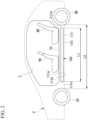
- FIG. 2 is a side view showing the electric power supplying module 100.
- the electric power supplying module 100 includes a module base 110.
- the module base 110 is a support member that supports various components included in the electric power supplying module 100.
- the module base 110 includes at least one of one or more housings and one or more base members.
- the module base 110 is formed of one case 111
- the case 111 is an example of a "housing".
- the case 111 is formed in a box shape.
- the case 111 includes, for example, an upper wall 111a, a lower wall 111b, a front wall 111c, a rear wall 111d, a left wall 111e (see FIG. 1 ), and a right wall 111f (see FIG. 1 ).
- the upper wall 111a is a wall portion along a horizontal direction.
- the lower wall 111b is a wall portion along the horizontal direction similarly to the upper wall 111a.
- the lower wall 111b is positioned below the upper wall 111a with a housing space between the lower wall 111b and the upper wall 111a.
- the front wall 111c is a wall portion along an up-down direction and the left-right direction.
- the front wall 111c connects a front-end portion of the upper wall 111a with a front-end portion of the lower wall 111b.
- the rear wall 111d is a wall portion along the up-down direction and the left-right direction.
- the rear wall 111d connects a rear-end portion of the upper wall 111a with a rear-end portion of the lower wall 111b.
- the left wall 111e is a wall portion along the up-down direction and the front-rear direction.
- the left wall 111e connects a left-end portion of the upper wall 111a with a left-end portion of the lower wall 111b.
- the right wall 111 f is a wall portion along the up-down direction and the front-rear direction.
- the right wall 111f connects a right-end portion of the upper wall 111a with a right-end portion of the lower wall 111b.
- housing used in the present application means a member that covers a component disposed inside the housing from two or more directions (for example, three or more directions).
- a frame body without the upper wall 111a or the lower wall 111b, a letter U-shaped member without the upper wall 111a, the lower wall 11 1b, or the rear wall 111d, or the like corresponds to an example of the "housing".
- the case 111 (the module base 110) is disposed under the floor of the vehicle V.
- the vehicle V includes a floor surface member 3a, which defines a floor surface of the vehicle interior 3.
- the case 111 (the module base 110) is disposed under the floor surface member 3a.
- a length L1 of the case 111 (the module base 110) in the front-rear direction is smaller than a distance L2 between the front wheel 2A and the rear wheel 2B.
- the case 111 (the module base 110) includes a front-end portion 110a, a rear-end portion 110b, a left-end portion 110c, and a right-end portion 110d.
- the front-end portion 110a When the vehicle V is viewed from above, the front-end portion 110a is disposed between a center C1 in the front-rear direction of the vehicle V and a front end Ea of the vehicle V. In a case where the case 111 (the module base 110) is divided into four areas in the front-rear direction of the vehicle V, the front-end portion 110a is a foremost area among the four divided areas.
- the rear-end portion 110b is disposed between the center C1 in the front-rear direction of the vehicle V and a rear end Eb of the vehicle V. In the case where the case 111 (the module base 110) is divided into four areas in the front-rear direction of the vehicle V, the rear-end portion 110b is a rearmost area among the four divided areas.
- the left-end portion 110c is disposed between a center C2 in the width direction of the vehicle V and a left end Ec of the vehicle V.
- the left-end portion 110c is a leftmost area among the four divided areas.
- the right-end portion 110d is disposed between the center C2 in the width direction of the vehicle V and a right end Ed of the vehicle V.
- the case 111 (the module base 110) is divided into four areas in the width direction of the vehicle V
- the right-end portion 110d is a rightmost area among the four divided areas.
- the case 111 is made of metal, for example.
- the case 111 is electrically connected with the ground of the vehicle V.
- the case 111 is electrically connected with the ground, and thus functions as an electromagnetic interference (EMI) countermeasure component related to components included in the electric power supplying module 100.
- EMI electromagnetic interference
- FIG. 3 is a block diagram illustrating an electric constitution of the electric power supplying module 100.
- the electric power supplying module 100 includes, for example, a high-voltage battery 120, a low-voltage battery 130, an inverter assembly 140, a power distribution unit 150, an electronic control unit (ECU) unit 160, and a control device 170.
- ECU electronice control unit
- the high-voltage battery 120, the low-voltage battery 130, the inverter assembly 140, the power distribution unit 150, the ECU unit 160, and the control device 170 are supported by the module base 110.
- the high-voltage battery 120, the low-voltage battery 130, the inverter assembly 140, the power distribution unit 150, the ECU unit 160, and the control device 170 are housed in one case 111.
- the high-voltage battery 120 is a battery capable of supplying high-voltage power equal to or higher than 100 V (for example, 350 V).
- the high-voltage battery 120 is formed of, for example, a plurality of battery cells electrically connected in series or in parallel.
- the high-voltage battery 120 is an example of a "first battery".
- the low-voltage battery 130 is a battery capable of supplying low-voltage power lower than 100 V (for example, 12 V).
- the low-voltage battery 130 is formed of, for example, a plurality of battery cells electrically connected in series or in parallel.
- the low-voltage battery 130 is an example of a "second battery”.
- the inverter assembly 140 is a functional unit that converts the electric power supplied from the high-voltage battery 120.
- the inverter assembly 140 is an example of a "power conversion unit”.
- the inverter assembly 140 includes, for example, a DC-DC converter 141, a motor inverter 142, a heat pump inverter 143, and a charger converter 144.
- the term “power conversion unit” used in the present application may have at least one of a function of converting DC power supplied from the battery into AC power and a function of converting DC power supplied from the battery into another type of DC power having a different voltage (DC power that has been boosted or stepped down).
- the term “power conversion unit” used in the present application may be implemented by at least one of the DC-DC converter 141, the motor inverter 142, the heat pump inverter 143, and the charger converter 144.
- the DC-DC converter 141 is a power conversion device that converts DC power of a certain voltage supplied from the high-voltage battery 120 into DC power of a voltage lower than the above voltage. For example, the DC-DC converter 141 converts high-voltage DC power supplied from the high-voltage battery 120 into low-voltage DC power. In the present embodiment, the DC-DC converter 141 converts the high-voltage DC power supplied from the high-voltage battery 120 into two or more types of low-voltage DC power (for example, DC power of 12 V and DC power of 5 V). The DC-DC converter 141 outputs the obtained low-voltage DC power to the power distribution unit 150.
- the DC-DC converter 141 is an example of a "first power conversion device".
- the motor inverter 142 is a power conversion device that converts the DC power supplied from the high-voltage battery 120 into AC power (for example, three-phase AC). For example, the motor inverter 142 converts the high-voltage DC power supplied from the high-voltage battery 120 into high-voltage AC power. The motor inverter 142 outputs the obtained AC power to the motor 10 through a high-voltage connector 181 to be described later.
- the motor inverter 142 is an example of a "second power conversion device".
- the heat pump inverter 143 is a power conversion device that converts the DC power supplied from the high-voltage battery 120 into AC power (for example, single-phase AC). For example, the heat pump inverter 143 converts the high-voltage DC power supplied from the high-voltage battery 120 into high-voltage AC power. The heat pump inverter 143 outputs the obtained AC power to the heat pump 21 through a high-voltage connector 182 to be described later.
- the heat pump inverter 143 is another example of the "second power conversion device".
- the charger converter 144 is a power conversion device that converts AC power for charging supplied from the outside into DC power.
- the charger converter 144 is electrically connected with the charging port 41 through a high-voltage connector 183 to be described later.
- the charger converter 144 converts high-voltage AC power supplied from the outside through the charging port 41 and the high-voltage connector 183 into high-voltage DC power.
- the charger converter 144 outputs the obtained DC power to the high-voltage battery 120.
- the power distribution unit 150 is a distribution device that distributes and supplies the power that has been supplied to the power distribution unit 150 to a plurality of load units (and/or a plurality of loads) of the vehicle V.
- the power distribution unit 150 distributes and supplies the low-voltage DC power that has been supplied from the DC-DC converter 141 to a plurality of load units (for example, the front auxiliary equipment 22L and 22R, the panel auxiliary equipment 23, the door auxiliary equipment 31AL, 31BL, 31AR, and 31BR, the floor auxiliary equipment 32FA and 32FB, the rear auxiliary equipment 42L and 42R, the ECU unit 160, and the control device 170).
- the power distribution unit 150 is connected with the low-voltage battery 130.
- the power distribution unit 150 distributes and supplies the low-voltage DC power supplied from the low-voltage battery 130 to at least a part of the above plurality of load units.
- the power distribution unit 150 distributes and supplies the low-voltage DC power supplied from the low-voltage battery 130 to at least a part of the plurality of load units, for example, at the time of startup before the vehicle V starts operating.
- the power distribution unit 150 supplies a part of the distributed power to the front auxiliary equipment 22 through a low-voltage connector 191 to be described later.
- the power distribution unit 150 supplies a part of the distributed power to the panel auxiliary equipment 23 through a low-voltage connector 192 to be described later.
- the power distribution unit 150 supplies a part of the distributed power to the door auxiliary equipment 31 through a low-voltage connector 193 (or the low-voltage connector 191, see FIG. 1 ) to be described later.
- the power distribution unit 150 supplies a part of the distributed power to the floor auxiliary equipment 32 through a low-voltage connector 194 to be described later.
- the power distribution unit 150 supplies a part of the distributed power to the rear auxiliary equipment 42 through a low-voltage connector 195 to be described later.
- the power distribution unit 150 supplies a part of the distributed power to the ECU unit 160 and the control device 170 in the electric power supplying module 100.
- FIG. 4 is a block diagram showing details of the power distribution unit 150.
- the power distribution unit 150 includes power distributors 151 to 155.
- the power distributor 151 is an electric circuit portion that distributes the power that has been supplied to the power distribution unit 150 to a plurality of loads included in the front auxiliary equipment 22.
- the power distributor 152 is an electric circuit portion that distributes the power that has been supplied to the power distribution unit 150 to a plurality of loads included in the panel auxiliary equipment 23.
- the power distributor 153 is an electric circuit portion that distributes the power that has been supplied to the power distribution unit 150 to a plurality of loads included in the door auxiliary equipment 31.
- the power distributor 154 is an electric circuit portion that distributes the power that has been supplied to the power distribution unit 150 to a plurality of loads included in the floor auxiliary equipment 32.
- the power distributor 155 is an electric circuit portion that distributes the power that has been supplied to the power distribution unit 150 to a plurality of loads included in the rear auxiliary equipment 42.
- Each of the power distributors 151 to 155 includes a plurality of power lines PL respectively corresponding to a plurality of loads.
- a switching element SW for example, a relay or a transistor
- a cut-off component F for example, a fuse
- the switching element SW switches the state of the power line PL provided with the switching element SW between a conduction state and a non-conduction state, based on a signal from the control device 170 to be described later.
- the cut-off component F cuts off the power line PL, which is provided with the cut-off component F.
- the ECU unit 160 is a control device that controls electric components mounted on the vehicle V.
- the ECU unit 160 includes, for example, a body ECU 161 and a brake ECU 162.
- the body ECU 161 is a control device that controls the above-described vehicle-mounted components (for example, the front auxiliary equipment 22, the panel auxiliary equipment 23, the door auxiliary equipment 31, the floor auxiliary equipment 32, and the rear auxiliary equipment 42).
- the brake ECU 162 is a control device that controls the brake of the vehicle V.
- the ECU unit 160 is an example of the "load unit".
- the control device 170 is a control device that controls the electric power supplying module 100.
- the control device 170 includes, for example, a battery management system. By controlling, for example, the inverter assembly 140 and the power distribution unit 150, the battery management system controls the power supplied from the electric power supplying module 100 to the plurality of load units.
- the control device 170 is an example of the "load unit".
- the electric power supplying module 100 includes a plurality of high-voltage connectors 181 to 183 and a plurality of low-voltage connectors 191 to 195.
- the high-voltage connectors 181 to 183 are each a connector corresponding to high voltage.
- the low-voltage connectors 191 to 195 are each a connector corresponding to low voltage.
- the plurality of high-voltage connectors 181 to 183 and the plurality of low-voltage connectors 191 to 195 are supported by the case 111 (the module base 110).
- the connector is supported by the case “the connector is provided in the case”, and “the connector is disposed in an end portion of the case” are not limited to a case where the connector is fixed to an outer surface of the case 111, and are applicable to a case where the connector is housed inside the case 111 and exposed to the outside of the case 111 through an opening of the case 111.
- the plurality of high-voltage connectors 181 include a high-voltage connector 181A and a high-voltage connector 181B.
- the high-voltage connector 181A is a connector corresponding to the front motor 10A.
- the high-voltage connector 181A is disposed at the front-end portion 110a of the case 111.
- a routing member 200A is connected with the high-voltage connector 181A.
- the routing member 200A is a routing member that supplies the high-voltage AC power to the front motor 10A.
- the high-voltage connector 181B is a connector corresponding to the rear motor 10B.
- the high-voltage connector 181B is disposed at the rear-end portion 110b of the case 111.
- a routing member 200B is connected with the high-voltage connector 181B.
- the routing member 200B is a routing member that supplies the high-voltage AC power from the high-voltage connector 181B to the rear motor 10B.
- the high-voltage connector 182 is a connector corresponding to the heat pump 21.
- the high-voltage connector 182 is disposed at the front-end portion 110a of the case 111.
- a routing member 200C is connected with the high-voltage connector 182.
- the routing member 200C is a routing member that supplies the high-voltage AC power to the heat pump 21.
- the high-voltage connector 183 is a connector corresponding to the charging port 41.
- the high-voltage connector 183 is disposed at the rear-end portion 110b of the case 111.
- a routing member 200D is connected with the high-voltage connector 183.
- the routing member 200D is a routing member that supplies the high-voltage AC power from the charging port 41 to the high-voltage connector 183.
- the plurality of low-voltage connectors 191 include a low-voltage connector 191L and a low-voltage connector 191R.
- the low-voltage connector 191L is a connector corresponding to the left-front auxiliary equipment 22L.
- the low-voltage connector 191L is disposed at the front-end portion 110a of the case 111 that is also a left-front corner portion of the case 111 in the left-end portion 110c.
- a routing member 200E is connected with the low-voltage connector 191L.
- the routing member 200E is a routing member that supplies the low-voltage DC power to the left-front auxiliary equipment 22L.
- the routing member 200E is a routing member that electrically supplies the power that has been distributed by the power distributor 151 to a plurality of loads included in the left-front auxiliary equipment 22L in parallel.
- a routing member 200G which supplies the low-voltage DC power to the door auxiliary equipment 31AL, is also connected with the connector 191L.
- the routing member 200G is a routing member that electrically supplies the power that has been distributed by the power distributor 151 to a plurality of loads included in the door auxiliary equipment 31AL in parallel.
- the low-voltage connector 191R is a connector corresponding to the right-front auxiliary equipment 22R.
- the low-voltage connector 191R is disposed at the front-end portion 110a of the case 111 that is also a right-front corner portion of the case 111 in the right-end portion 110d.
- a routing member 200F is connected with the low-voltage connector 191R.
- the routing member 200F is a routing member that supplies the low-voltage DC power to the right-front auxiliary equipment 22R.
- the routing member 200F is a routing member that electrically supplies the power that has been distributed by the power distributor 151 to a plurality of loads included in the right-front auxiliary equipment 22R in parallel.
- a routing member 200H which supplies the low-voltage DC power to the door auxiliary equipment 31AR, is also connected with the connector 191R.
- the routing member 200H is a routing member that electrically supplies the power that has been distributed by the power distributor 151 to a plurality of loads included in the door auxiliary equipment 31AR in parallel.
- the low-voltage connector 192 is a connector corresponding to the panel auxiliary equipment 23.
- the low-voltage connector 192 is disposed at the front-end portion 110a of the case 111.
- a routing member 200G is connected with the low-voltage connector 192.
- the routing member 200G is a routing member that supplies the low-voltage DC power to the panel auxiliary equipment 23.
- the routing member 200G is a routing member that electrically supplies the power that has been distributed by the power distributor 152 to a plurality of loads included in the panel auxiliary equipment 23 in parallel.
- a low-voltage connector 193L is a connector corresponding to the door auxiliary equipment 31BL.
- the low-voltage connector 193L is disposed at a left-end portion 110c of the case 111.
- a routing member 200I is connected with the low-voltage connector 193L.
- the routing member 200I is a routing member that supplies the low-voltage DC power to the door auxiliary equipment 31BL.
- the routing member 200I is a routing member that electrically supplies the power that has been distributed by the power distributor 153 to a plurality of loads included in the door auxiliary equipment 31 in parallel.
- the low-voltage connector 193R is a connector corresponding to the door auxiliary equipment 31BR.
- the low-voltage connector 193R is disposed at a right-end portion 110d of the case 111.
- a routing member 200J is connected with the low-voltage connector 193R.
- the routing member 200J is a routing member that supplies the low-voltage DC power to the door auxiliary equipment 31BR.
- the routing member 200J is a routing member that electrically supplies the power that has been distributed by the power distributor 153 to a plurality of loads included in the door auxiliary equipment 31 in parallel.
- the low-voltage connector 194 is a connector corresponding to the floor auxiliary equipment 32.
- the low-voltage connector 194 is disposed, for example, in the central section in the left-right direction of the case 111.
- a routing member 200K is connected with the low-voltage connector 194.
- the routing member 200K is a routing member that supplies the low-voltage DC power to the floor auxiliary equipment 32.
- the routing member 200K is a routing member that electrically supplies the power that has been distributed by the power distributor 154 to a plurality of loads included in the floor auxiliary equipment 32 in parallel.
- the plurality of low-voltage connectors 195 include a low-voltage connector 195L and a low-voltage connector 195R.
- the low-voltage connector 195L is a connector corresponding to the left-rear auxiliary equipment 42L.
- the low-voltage connector 195L is disposed at the rear-end portion 110b of the case 111 that is also a left-rear corner portion of the case 111 in the left-end portion 110c.
- a routing member 200M is connected with the low-voltage connector 195L.
- the routing member 200M is a routing member that supplies the low-voltage DC power to the left-rear auxiliary equipment 42L.
- the routing member 200M is a routing member that electrically supplies the power that has been distributed by the power distributor 155 to a plurality of loads included in the left-rear auxiliary equipment 42L in parallel.
- the low-voltage connector 195R is a connector corresponding to the right-rear auxiliary equipment 42R.
- the low-voltage connector 195R is disposed at the rear-end portion 110b of the case 111 that is also a right-rear corner portion of the case 111 in the right-end portion 110d.
- a routing member 200N is connected with the low-voltage connector 195R.
- the routing member 200N is a routing member that supplies the low-voltage DC power to the right-rear auxiliary equipment 42R.
- the routing member 200N is a routing member that electrically supplies the power that has been distributed by the power distributor 155 to a plurality of loads included in the right-rear auxiliary equipment 42R in parallel.
- each routing member 200 may include a signal line for transmitting and receiving signals between the ECU unit 160 and each load unit, in addition to the power line.
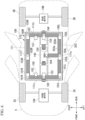
- FIGS. 5 and 6 are diagrams each illustrating an arrangement example in the electric power supplying module 100.
- the high-voltage battery 120 includes a first battery unit 121 and a second battery unit 122.
- the first battery unit 121 and the second battery unit 122 are arranged side by side in the width direction of the vehicle V.
- a gap S is provided between the first battery unit 121 and the second battery unit 122.
- the low-voltage battery 130, the inverter assembly 140, the ECU unit 160, and the control device 170 are disposed in the gap S between the first battery unit 121 and the second battery unit 122.
- the inverter assembly 140 is disposed in the central section of the electric power supplying module 100 in the front-rear direction of the vehicle V.
- the low-voltage battery 130 is disposed between the inverter assembly 140 and the rear wall 111d of the case 111.
- the ECU unit 160 and the control device 170 are disposed between the inverter assembly 140 and the front wall 111c of the case 111.
- the high-voltage connector 181A is fixed to the front wall 111c of the case 111.
- an electric connection member 201 is provided between the high-voltage connector 181A and the inverter assembly 140.
- the electric connection member 201 includes, for example, a plurality of (for example, three) bus bars 201a and a protection member 201b.
- the bus bar 201a is a metal plate member.
- the plurality of bus bars 201a are arranged side by side in the width direction of the vehicle V.
- the plurality of bus bars 201 a are adapted to, for example, a U-phase, a V-phase, and a W-phase of three-phase alternating current.
- the protection member 201b is an insulation member that covers the plurality of bus bars 201a.
- a protection member 202b electrically insulates the plurality of bus bars 201a from one another.
- the electric connection member 201 extends to pass below, for example, the ECU unit 160 and the control device 170.
- the high-voltage connector 181B is fixed to the rear wall 111d of the case 111.
- an electric connection member 202 is provided between the high-voltage connector 181B and the inverter assembly 140.
- the electric connection member 202 includes, for example, a plurality of bus bars 202a and a protection member 202b.
- the bus bar 202a is a metal plate member.
- the plurality of bus bars 202a are arranged side by side in the width direction of the vehicle V.
- the plurality of bus bars 202a are adapted to, for example, a U-phase, a V-phase, and a W-phase of three-phase alternating current.
- the protection member 202b is an insulation member that covers the plurality of bus bars 202a.
- the protection member 202b electrically insulates the plurality of bus bars 202a from each other.
- the electric connection member 202 extends to pass below, for example, the low-voltage battery 130.
- the electric power supplying module 100 includes an electric connection member 203.
- the electric connection member 203 is connected with the inverter assembly 140.
- the electric connection member 203 includes, for example, a plurality of (for example, three) bus bars 203a and a protection member 203b.
- the bus bar 203a is a metal plate member.
- the plurality of bus bars 203a are arranged side by side in the horizontal direction.
- the plurality of bus bars 203a extend in parallel with one another.
- the plurality of bus bars 203a correspond to, for example, DC power of 12 V and DC power of 5 V that have been respectively output from the DC-DC converter 141, and single-phase AC power that has been output from the heat pump inverter 143.
- the protection member 203b is an insulation member that covers the plurality of bus bars 203a.
- the protection member 203b electrically insulates the plurality of bus bars 203a from each other.
- the electric connection member 203 extends sequentially along a part of the left wall 111e, the rear wall 111d, the right wall 111f, the front wall 111c, and another part of the left wall 111e of the case 111.
- the electric connection member 203 extends, for example, to sequentially pass below the power distributors 151 to 155 of the power distribution unit 150.
- the power distributors 151 to 155 of the power distribution unit 150 are disposed inside the case 111 in a distributed manner.
- the power distributors 151 to 155 of the power distribution unit 150 are attached to the cases 111 (the module base 110) to be spaced apart from one another.
- the power distribution unit 150 includes a power distributor 151L and a power distributor 151R as the power distributor 151.
- the power distributor 151L is disposed at the left-front corner portion of the case 111 so as to be positioned below the low-voltage connector 191L.
- the power distributor 151L is connected with the electric connection member 203 at the left-front corner portion of the case 111.
- the power distributor 151R is disposed at the right-front corner portion of the case 111 so as to be positioned below the low-voltage connector 191R.
- the power distributor 151R is connected with the electric connection member 203 at the right-front corner portion of the case 111.
- the power distributor 152 is disposed at the front-end portion 110a of the case 111 so as to be positioned below the low-voltage connector 192.
- the power distributor 152 is connected with the electric connection member 203 at the front-end portion 110a of the case 111.
- the power distribution unit 150 includes a power distributor 153L and a power distributor 153R as the power distributor 153.
- the power distributor 153L is disposed at the left-end portion 110e of the case 111 so as to be positioned below the low-voltage connector 193L.
- the power distributor 153L is connected with the electric connection member 203 at the left-end portion 110e of the case 111.
- the power distributor 153R is disposed at the right-end portion 110f of the case 111 so as to be positioned below the low-voltage connector 193R.
- the power distributor 155L is connected with the electric connection member 203 at the right-end portion 110f of the case 111.
- the power distributor 154 is disposed in the central section in the left-right direction of the case 111 so as to be positioned below the low-voltage connector 194.
- the power distributor 154 is connected with the electric connection member 203 in the central section in the left-right direction of the case 111.
- the power distribution unit 150 includes a power distributor 155L and a power distributor 155R as the power distributor 155.
- the power distributor 155L is disposed at the left-rear corner portion of the case 111 so as to be positioned below the low-voltage connector 195L.
- the power distributor 155L is connected with the electric connection member 203 at the left-rear corner portion of the case 111.
- the power distributor 155R is disposed at the right-rear corner portion of the case 111 so as to be positioned below the low-voltage connector 195R.
- the power distributor 155R is connected with the electric connection member 203 at the right-rear corner portion of the case 111.
- the electric power supplying module 100 includes a power distributor 156 and a connection component 157.
- the power distributor 156 and the connection component 157 each includes a power line PL, a switching element SW, and a cut-off component F.
- the power distributor 156 is a connection component that connects the high-voltage connector 182 with the electric connection member 203.
- the power distributor 156 is disposed at the front-end portion 110a of case 111 so as to be positioned below the high-voltage connector 182.
- the power distributor 156 is connected with the electric connection member 203 at the front-end portion 110a of the case 111.
- the connection component 157 is a component that connects the high-voltage connector 183 with the electric connection member 203.
- the connection component 157 is disposed at the rear-end portion 110b of case 111 so as to be positioned below the high-voltage connector 183.
- the connection component 157 is connected with the electric connection member 203 at the rear-end portion 110b of the case 111.
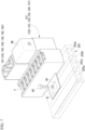
- FIG. 7 is a perspective view showing the power distributor 151 and the connector 191.
- the power distributor 151 and the low-voltage connector 191 are provided as one unit.
- the power distributor 151 is fixed to the case 111, and thus the low-voltage connector 191 is supported by the case 111.
- the power distributor 151 includes a bus bar B, which is connected with the electric connection member 203. When viewed from above, the bus bar B overlaps the bus bar 203a, which is a connection destination included in the electric connection member 203.
- the electric connection member 203 includes an opening portion OP, which exposes the bus bar 203a as the connection destination at a position corresponding to the bus bar B.
- the bus bar B is connected with the bus bar 203a as the connection destination via a fastening member BT such as a bolt, for example.
- the above-described constitution related to the power distributor 151 is also applied to the power distributors 152 to 156 and the connection component 157.
- an electric power supplying system including a battery disposed under a floor and a power conversion unit that converts the power supplied from the above battery.
- the power conversion unit is disposed in the front section of the vehicle.
- a long routing member that connects each section of the vehicle including the rear section of the vehicle with the front section of the vehicle is necessary.
- the electric power supplying module 100 includes the module base 110, which is disposed under the floor of the vehicle V, the power conversion unit supported by the module base 110, the first connector supported by the module base 110, and the second connector supported by the module base 110.
- the routing member 200 which supplies first power output from the above power conversion unit to the first load unit, is connectable with the first connector.
- the routing member 200 which supplies second power output from the power conversion unit to the second load unit, is connectable with the second connector.
- the length of the first routing member can be shortened to a length that connects the first load unit with the first connector disposed under the floor of the vehicle.
- the length of the second routing member can be shortened to a length that connects the second load unit with the second connector disposed under the floor of the vehicle. Therefore, the lengths of the routing members can be shortened.
- a large difference in length between the first routing member and the second routing member can be avoided.
- the module base 110 which is disposed under the floor of the vehicle V, and the power conversion unit, the first connector, and the second connector, which are respectively supported by the module base 110, are included, so that the electric power supplying module 100, which is for a general purpose and which is easily adapted to a plurality of vehicle types, can be provided.
- the plurality of power distributors 151 to 155 are arranged in a distributed manner inside the case 111.
- the power distributors 151 to 155 which are heat generating components, are arranged in a distributed manner, so that the concentration of heat generation in a partial area can be suppressed.
- the routing members thickened as a countermeasure against the heat generation can be made thinner.
- the second embodiment is different from the first embodiment in that at least a part of the high-voltage battery 120 is detachably attached to the electric power supplying module 100. Note that the constitutions except for those to be described below are the same as the constitutions in the first embodiment.
- FIG. 8 is a diagram illustrating a constitution example of the electric power supplying module 100 in the second embodiment.
- the low-voltage battery 130, the inverter assembly 140, the power distribution unit 150, the ECU unit 160, and the control device 170 are housed in the case 111.
- the first battery unit 121 and the second battery unit 122 are each housed in a case 112.
- the case 112, in which the first battery unit 121 or the second battery unit 122 is housed, is detachably attached to the electric power supplying module 100.
- the first battery unit 121 or the second battery unit 122 is detached together with the case 112 from the electric power supplying module 100.
- the first battery unit 121 or the second battery unit 122 which has been charged, is attached together with the case 112 to the electric power supplying module 100.
- the lengths of the routing members can be shortened.
- the third embodiment is different from the first embodiment in that the module base 110 is formed of a plurality of cases 301 and 302. Note that the constitutions except for those to be described below are the same as the constitutions in the first embodiment.
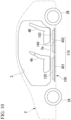
- FIG. 9 is a side view showing the electric power supplying module 100 in the third embodiment.
- the module base 110 is formed of the plurality of cases 301 and 302.
- the plurality of cases 301 and 302 are disposed under the floor of the vehicle V, for example, side by side in the horizontal direction.
- the high-voltage battery 120, the low-voltage battery 130, the DC-DC converter 141, the motor inverter 142, the heat pump inverter 143, the charger converter 144, the power distribution unit 150, the ECU unit 160, and the control device 170 are separately housed in the plurality of cases 301 and 302. Also in such a constitution, the lengths of the routing members can be shortened.
- the fourth embodiment is different from the first embodiment in that the module base 110 is formed of base members 401 and 402. Note that the constitutions except for those to be described below are the same as the constitutions in the first embodiment.
- FIG. 10 is a side view showing the electric power supplying module 100 in the fourth embodiment.
- the module base 110 is formed of one or more (for example, a plurality of) base members 401 and 402.
- Each of the base members 401 and 402 is a plate-shaped member.
- Each of the base members 401 and 402 may be a plate member made of metal or synthetic resin, a substrate on which an electric circuit is formed, or the like.
- the base members 401 and 402 are disposed under the floor of the vehicle V, for example, side by side in the horizontal direction.
- the high-voltage battery 120, the low-voltage battery 130, the DC-DC converter 141, the motor inverter 142, the heat pump inverter 143, the charger converter 144, the power distribution unit 150, the ECU unit 160, and the control device 170 are mounted on the above one or more (for example, a plurality of) base members 401 and 402. Also in such a constitution, the lengths of the routing members can be shortened.
- the length of the routing member that supplies the power to the plurality of loads can be shortened to a length that connects the plurality of loads with the connector disposed under the floor of the vehicle.
- the lengths of the routing members can be shortened.
Landscapes
- Engineering & Computer Science (AREA)
- Power Engineering (AREA)
- Mechanical Engineering (AREA)
- Transportation (AREA)
- Sustainable Energy (AREA)
- Life Sciences & Earth Sciences (AREA)
- Sustainable Development (AREA)
- Chemical & Material Sciences (AREA)
- Combustion & Propulsion (AREA)
- Electric Propulsion And Braking For Vehicles (AREA)
- Arrangement Or Mounting Of Propulsion Units For Vehicles (AREA)
- Secondary Cells (AREA)
- Battery Mounting, Suspending (AREA)
Abstract
An electric power supplying module includes a module base, a power conversion unit, a first connector, and a second connector. The module base is disposed under a floor of a vehicle. The power conversion unit is supported by the module base, and converts power supplied from a battery. The first connector is supported by the module base, and is connectable with a first routing member that supplies first power output from the power conversion unit to a first load unit of the vehicle. The second connector is supported by the module base, and is connectable with a second routing member that supplies second power output from the power conversion unit to a second load unit of the vehicle.
Description
- Embodiments of the present invention relate to an electric power supplying module.
- A vehicle power supply system including a battery and an electric junction box is known. In the above vehicle power supply system, the power from the battery is distributed to a plurality of loads in a vehicle via the electric junction box disposed in a front section of the vehicle.
- Patent Document 1:
Japanese Unexamined Patent Application, First Publication No. 2018-065485 - An electric power supplying system for a vehicle, by the way, includes a power conversion unit that converts the power supplied from the battery. In a case where such a power conversion unit is disposed in a front section or a rear section of the vehicle, routing members provided in the vehicle may be long.
- An embodiment of the present invention provides an electric power supplying module by which the lengths of routing members can be shortened.
- An electric power supplying module according to an embodiment of the present invention includes a module base, a power conversion unit, a first connector, and a second connector. The module base is disposed under a floor of a vehicle. The power conversion unit is supported by the module base, and converts power supplied from a battery. The first connector is supported by the module base, and is connectable with a first routing member that supplies first power output from the power conversion unit to a first load unit of the vehicle. The second connector is supported by the module base, and is connectable with a second routing member that supplies second power output from the power conversion unit to a second load unit of the vehicle.
- According to the electric power supplying module in one embodiment of the present invention, the lengths of the routing members can be shortened.
-
-
FIG. 1 is a diagram illustrating a constitution of an electric power supplying system in a first embodiment; -
FIG. 2 is a side view showing an electric power supplying module in the first embodiment; -
FIG. 3 is a block diagram illustrating an electric constitution of the electric power supplying module in the first embodiment; -
FIG. 4 is a block diagram showing details of a power distribution unit in the first embodiment; -
FIG. 5 is a cross-sectional view illustrating an arrangement example in the electric power supplying module in the first embodiment; -
FIG. 6 is a cross-sectional view illustrating an arrangement example in the electric power supplying module in the first embodiment; -
FIG. 7 is a perspective view showing a power conversion unit and a connector in the first embodiment; -
FIG. 8 is a cross-sectional view illustrating an arrangement example in an electric power supplying module in a second embodiment; -
FIG. 9 is a side view showing an electric power supplying module in a third embodiment; and -
FIG. 10 is a side view showing an electric power supplying module in a fourth embodiment. - Hereinafter, embodiments of the present invention will be described with reference to the drawings. In the following description, constitutions having the same or similar functions are denoted by the same reference numbers. In addition, redundant descriptions of these constitutions will be omitted, in some cases. Further, with regard to reference numbers accompanied by alphabetic characters for distinction, in a case where they are not necessarily distinguished from each other, the alphabetic characters at the end may be omitted.
- In the present application, terms are defined as follows. The term "connection" is not limited to a mechanical connection, and can include an electric connection. That is, the term "connection" is not limited to a case where two elements to be connected are directly connected, and may include a case where two elements to be connected are connected with another element interposed between them. The term "supported" is not limited to a case of being supported in direct contact, and may include a case of being supported with another element interposed between them. The term "high voltage" or "high-voltage" means a voltage equal to or higher than 48 V. The term "low voltage" or "low-voltage" means a voltage lower than 48 V. In addition, in the present application, front, rear, left, and right are defined based on an advancing direction of the vehicle.
-
FIG. 1 is a diagram illustrating a constitution of an electric power supplying system 1 in a first embodiment. The electric power supplying system 1 is mounted on a vehicle V. The vehicle V is an electric vehicle such as an electric vehicle (EV), a hybrid electric vehicle (HEV), or a plug-in hybrid electric vehicle (PHEV). The vehicle V is, for example, a four wheeled vehicle. However, the vehicle V may be a three wheeled vehicle or a five or more wheeled vehicle. - First, a load unit of the vehicle V will be described.
- As illustrated in
FIG. 1 , the vehicle V includes, for example, afront motor 10A, arear motor 10B, a front section vehicle-mountedcomponent 20, a vehicle interior vehicle-mountedcomponent 30, and a rear section vehicle-mountedcomponent 40. - The
front motor 10A is a drive source for traveling that actuatesfront wheels 2A of the vehicle V. Thefront motor 10A is disposed on, for example, a front side relative to avehicle interior 3 of the vehicle V (seeFIG. 2 ). The operating voltage of thefront motor 10A is, for example, 300 V to 400 V. Thefront motor 10A is an example of a "load unit". Thefront motor 10A is an example of a "high-voltage load unit" that operates at a high voltage. - The
rear motor 10B is a drive source for traveling that actuatesrear wheels 2B of the vehicle V. Therear motor 10B is disposed on, for example, a rear side relative to thevehicle interior 3 of the vehicle V (seeFIG. 2 ). The operating voltage of therear motor 10B is, for example, 300 V to 400 V. Therear motor 10B is an example of the "load unit". Therear motor 10B is an example of the "high-voltage load unit" that operates at a high voltage. Hereinafter, thefront motor 10A and therear motor 10B will be referred to as "themotor 10", in a case where that are not distinguished from each other. - The front section vehicle-mounted
component 20 is a vehicle-mounted component disposed on a front side relative to afront seat 4A of the vehicle V (seeFIG. 2 ). The front section vehicle-mountedcomponent 20 includes, for example, aheat pump 21, left-frontauxiliary equipment 22L, right-frontauxiliary equipment 22R, and instrument panel auxiliary equipment 23 (hereinafter, referred to as "panelauxiliary equipment 23"). - The
heat pump 21 is a device for conditioning the air in the vehicle V. Theheat pump 21 is an example of the "load unit". Theheat pump 21 is an example of the "high-voltage load unit" that operates at a high voltage. - The left-front
auxiliary equipment 22L denotes a vehicle-mounted component disposed in a left-front section of the vehicle V. The right-frontauxiliary equipment 22R denotes a vehicle-mounted component disposed in a right-front section of the vehicle V. Hereinafter, in a case where the left-frontauxiliary equipment 22L and the right-frontauxiliary equipment 22R are not distinguished from each other, they will be referred to as "the frontauxiliary equipment 22". The frontauxiliary equipment 22 is an example of the "load unit". The frontauxiliary equipment 22 is an example of a "low-voltage load unit" that operates at a low voltage. The frontauxiliary equipment 22 includes, for example, a plurality of loads that operate independently of each other. The frontauxiliary equipment 22 includes, for example, aheadlight 22a and adirection indicator 22b as the plurality of loads (seeFIG. 4 ). - The panel
auxiliary equipment 23 includes one or more vehicle-mounted components related to an instrument panel. The panelauxiliary equipment 23 is disposed, for example, in a central section in a width direction (a left-right direction) of the vehicle V. The panelauxiliary equipment 23 is an example of the "load unit". The panelauxiliary equipment 23 is an example of the "low-voltage load unit" that operates at a low voltage. The panelauxiliary equipment 23 includes, for example, a plurality of loads that operate independently of each other. The panelauxiliary equipment 23 includes, for example, ameter 23a and anavigation device 23b as the plurality of loads (seeFIG. 4 ). - The vehicle interior vehicle-mounted
component 30 is a vehicle-mounted component related to thevehicle interior 3. The vehicle interior vehicle-mountedcomponent 30 is mounted in an area corresponding to thevehicle interior 3 in a front-rear direction of the vehicle V. The vehicle interior vehicle-mountedcomponent 30 includes, for example, first to fourth door auxiliary equipment 31AL, 31BL, 31AR, and 31BR, and first and second floor auxiliary equipment 32FA and 32FB. - The first door auxiliary equipment 31AL denotes a vehicle-mounted component mounted on a left-front door. The second door auxiliary equipment 31BL denotes a vehicle-mounted component mounted on a left-rear door. The first door auxiliary equipment 31AL and the second door auxiliary equipment 31BL are disposed in a left-end portion of the vehicle V. The third door auxiliary equipment 31AR denotes a vehicle-mounted component mounted on a right-front door. The fourth door auxiliary equipment 31BR denotes a vehicle-mounted component mounted on a right-rear door. The third door auxiliary equipment 31AR and the fourth door auxiliary equipment 31BR are disposed in a right-end portion of the vehicle V.
- Hereinafter, in a case where pieces of the first to fourth door auxiliary equipment 31AL, 31BL, 31AR, and 31BR are not distinguished from one another, they will be referred to as "the door
auxiliary equipment 31". The doorauxiliary equipment 31 is an example of the "load unit". The doorauxiliary equipment 31 is an example of the "low-voltage load unit" that operates at a low voltage. The doorauxiliary equipment 31 includes, for example, a plurality of loads that operate independently of each other. The doorauxiliary equipment 31 includes, for example, apower window 31a and adoor lock mechanism 31b as the plurality of loads (seeFIG. 4 ). - The first floor auxiliary equipment 32FA denotes a vehicle-mounted component disposed to correspond to the
front seat 4A of the vehicle V (seeFIG. 2 ). The second floor auxiliary equipment 32FB denotes a vehicle-mounted component disposed to correspond to therear seat 4B of the vehicle V (seeFIG. 2 ). Hereinafter, in a case where pieces of the first and second floor auxiliary equipment 32FA and 32FB are not distinguished from each other, they will be referred to as "the floorauxiliary equipment 32". The floorauxiliary equipment 32 is an example of the "load unit". The floorauxiliary equipment 32 is an example of the "low-voltage load unit" that operates at a low voltage. The floorauxiliary equipment 32 includes, for example, a plurality of loads that operate independently of each other. The floorauxiliary equipment 32 includes, for example, adisplay device 32a and asound device 32b as the plurality of loads (seeFIG. 4 ). - The rear section vehicle-mounted
component 40 is a vehicle-mounted component disposed on a rear side relative to arear seat 4B of the vehicle V (seeFIG. 2 ). The rear section vehicle-mountedcomponent 40 includes, for example, a chargingport 41, left-rearauxiliary equipment 42L, and right-rearauxiliary equipment 42R. - The charging
port 41 denotes an electric connection portion to which an external charging device is connectable. The chargingport 41 is, for example, a charging port corresponding to AC power of 100 V or 200 V. However, the chargingport 41 may be a charging port for DC power. - The left-rear
auxiliary equipment 42L denotes a vehicle-mounted component disposed in a left-rear section of the vehicle V. The right-rearauxiliary equipment 42R denotes a vehicle-mounted component disposed in a right-rear section of the vehicle V. Hereinafter, in a case where the left-rearauxiliary equipment 42L and the right-rearauxiliary equipment 42R are not distinguished from each other, they will be referred to as "the rearauxiliary equipment 42". The rearauxiliary equipment 42 is an example of the "load unit". The rearauxiliary equipment 42 is an example of the "low-voltage load unit" that operates at a low voltage. The rearauxiliary equipment 42 includes, for example, a plurality of loads that operate independently of each other. The rearauxiliary equipment 42 includes, for example, atail lamp 42a and adirection indicator 42b as the plurality of loads (seeFIG. 4 ). - Next, a constitution of the electric power supplying system 1 will be described.
- As illustrated in
FIG. 1 , the electric power supplying system 1 includes an electricpower supplying module 100 and a plurality of routingmembers 200. The electricpower supplying module 100 is a module component in which a plurality of functional units related to supply of the power is integrated. The routingmember 200 is an electric connection component that extends between the electricpower supplying module 100 and the load unit. The routingmember 200 is, for example, a wire harness, but may be a cable, a bus bar, a flexible printed circuit board (FPC), or the like. -
FIG. 2 is a side view showing the electricpower supplying module 100. The electricpower supplying module 100 includes amodule base 110. Themodule base 110 is a support member that supports various components included in the electricpower supplying module 100. - The
module base 110 includes at least one of one or more housings and one or more base members. In the present embodiment, an example in which themodule base 110 is formed of onecase 111 will be described. Thecase 111 is an example of a "housing". - In the present embodiment, the
case 111 is formed in a box shape. Thecase 111 includes, for example, anupper wall 111a, alower wall 111b, afront wall 111c, arear wall 111d, aleft wall 111e (seeFIG. 1 ), and aright wall 111f (seeFIG. 1 ). - The
upper wall 111a is a wall portion along a horizontal direction. Thelower wall 111b is a wall portion along the horizontal direction similarly to theupper wall 111a. Thelower wall 111b is positioned below theupper wall 111a with a housing space between thelower wall 111b and theupper wall 111a. Thefront wall 111c is a wall portion along an up-down direction and the left-right direction. Thefront wall 111c connects a front-end portion of theupper wall 111a with a front-end portion of thelower wall 111b. Therear wall 111d is a wall portion along the up-down direction and the left-right direction. Therear wall 111d connects a rear-end portion of theupper wall 111a with a rear-end portion of thelower wall 111b. Theleft wall 111e is a wall portion along the up-down direction and the front-rear direction. Theleft wall 111e connects a left-end portion of theupper wall 111a with a left-end portion of thelower wall 111b. Theright wall 111 f is a wall portion along the up-down direction and the front-rear direction. Theright wall 111f connects a right-end portion of theupper wall 111a with a right-end portion of thelower wall 111b. - However, one or more of the
upper wall 111a, thelower wall 111b, thefront wall 111c, therear wall 111d, theleft wall 111e, and theright wall 111f may be omitted. The term "housing" used in the present application means a member that covers a component disposed inside the housing from two or more directions (for example, three or more directions). A frame body without theupper wall 111a or thelower wall 111b, a letter U-shaped member without theupper wall 111a, the lower wall 11 1b, or therear wall 111d, or the like corresponds to an example of the "housing". - As illustrated in
FIG. 2 , the case 111 (the module base 110) is disposed under the floor of the vehicle V. For example, the vehicle V includes afloor surface member 3a, which defines a floor surface of thevehicle interior 3. The case 111 (the module base 110) is disposed under thefloor surface member 3a. In the present embodiment, a length L1 of the case 111 (the module base 110) in the front-rear direction is smaller than a distance L2 between thefront wheel 2A and therear wheel 2B. - As illustrated in
FIG. 1 , the case 111 (the module base 110) includes a front-end portion 110a, a rear-end portion 110b, a left-end portion 110c, and a right-end portion 110d. - When the vehicle V is viewed from above, the front-
end portion 110a is disposed between a center C1 in the front-rear direction of the vehicle V and a front end Ea of the vehicle V. In a case where the case 111 (the module base 110) is divided into four areas in the front-rear direction of the vehicle V, the front-end portion 110a is a foremost area among the four divided areas. When the vehicle V is viewed from above, the rear-end portion 110b is disposed between the center C1 in the front-rear direction of the vehicle V and a rear end Eb of the vehicle V. In the case where the case 111 (the module base 110) is divided into four areas in the front-rear direction of the vehicle V, the rear-end portion 110b is a rearmost area among the four divided areas. - When the vehicle V is viewed from above, the left-
end portion 110c is disposed between a center C2 in the width direction of the vehicle V and a left end Ec of the vehicle V. In a case where the case 111 (the module base 110) is divided into four areas in the width direction of the vehicle V, the left-end portion 110c is a leftmost area among the four divided areas. When the vehicle V is viewed from above, the right-end portion 110d is disposed between the center C2 in the width direction of the vehicle V and a right end Ed of the vehicle V. In the case where the case 111 (the module base 110) is divided into four areas in the width direction of the vehicle V, the right-end portion 110d is a rightmost area among the four divided areas. - The
case 111 is made of metal, for example. Thecase 111 is electrically connected with the ground of the vehicle V. Thecase 111 is electrically connected with the ground, and thus functions as an electromagnetic interference (EMI) countermeasure component related to components included in the electricpower supplying module 100. -
FIG. 3 is a block diagram illustrating an electric constitution of the electricpower supplying module 100. The electricpower supplying module 100 includes, for example, a high-voltage battery 120, a low-voltage battery 130, aninverter assembly 140, apower distribution unit 150, an electronic control unit (ECU)unit 160, and acontrol device 170. - The high-
voltage battery 120, the low-voltage battery 130, theinverter assembly 140, thepower distribution unit 150, theECU unit 160, and thecontrol device 170 are supported by themodule base 110. In the present embodiment, the high-voltage battery 120, the low-voltage battery 130, theinverter assembly 140, thepower distribution unit 150, theECU unit 160, and thecontrol device 170 are housed in onecase 111. - The high-
voltage battery 120 is a battery capable of supplying high-voltage power equal to or higher than 100 V (for example, 350 V). The high-voltage battery 120 is formed of, for example, a plurality of battery cells electrically connected in series or in parallel. The high-voltage battery 120 is an example of a "first battery". - The low-
voltage battery 130 is a battery capable of supplying low-voltage power lower than 100 V (for example, 12 V). The low-voltage battery 130 is formed of, for example, a plurality of battery cells electrically connected in series or in parallel. The low-voltage battery 130 is an example of a "second battery". - The
inverter assembly 140 is a functional unit that converts the electric power supplied from the high-voltage battery 120. Theinverter assembly 140 is an example of a "power conversion unit". Theinverter assembly 140 includes, for example, a DC-DC converter 141, amotor inverter 142, aheat pump inverter 143, and acharger converter 144. - However, the term "power conversion unit" used in the present application may have at least one of a function of converting DC power supplied from the battery into AC power and a function of converting DC power supplied from the battery into another type of DC power having a different voltage (DC power that has been boosted or stepped down). The term "power conversion unit" used in the present application may be implemented by at least one of the DC-
DC converter 141, themotor inverter 142, theheat pump inverter 143, and thecharger converter 144. - The DC-
DC converter 141 is a power conversion device that converts DC power of a certain voltage supplied from the high-voltage battery 120 into DC power of a voltage lower than the above voltage. For example, the DC-DC converter 141 converts high-voltage DC power supplied from the high-voltage battery 120 into low-voltage DC power. In the present embodiment, the DC-DC converter 141 converts the high-voltage DC power supplied from the high-voltage battery 120 into two or more types of low-voltage DC power (for example, DC power of 12 V and DC power of 5 V). The DC-DC converter 141 outputs the obtained low-voltage DC power to thepower distribution unit 150. The DC-DC converter 141 is an example of a "first power conversion device". - The
motor inverter 142 is a power conversion device that converts the DC power supplied from the high-voltage battery 120 into AC power (for example, three-phase AC). For example, themotor inverter 142 converts the high-voltage DC power supplied from the high-voltage battery 120 into high-voltage AC power. Themotor inverter 142 outputs the obtained AC power to themotor 10 through a high-voltage connector 181 to be described later. Themotor inverter 142 is an example of a "second power conversion device". - The
heat pump inverter 143 is a power conversion device that converts the DC power supplied from the high-voltage battery 120 into AC power (for example, single-phase AC). For example, theheat pump inverter 143 converts the high-voltage DC power supplied from the high-voltage battery 120 into high-voltage AC power. Theheat pump inverter 143 outputs the obtained AC power to theheat pump 21 through a high-voltage connector 182 to be described later. Theheat pump inverter 143 is another example of the "second power conversion device". - The
charger converter 144 is a power conversion device that converts AC power for charging supplied from the outside into DC power. For example, thecharger converter 144 is electrically connected with the chargingport 41 through a high-voltage connector 183 to be described later. Thecharger converter 144 converts high-voltage AC power supplied from the outside through the chargingport 41 and the high-voltage connector 183 into high-voltage DC power. Thecharger converter 144 outputs the obtained DC power to the high-voltage battery 120. - The
power distribution unit 150 is a distribution device that distributes and supplies the power that has been supplied to thepower distribution unit 150 to a plurality of load units (and/or a plurality of loads) of the vehicle V. In the present embodiment, thepower distribution unit 150 distributes and supplies the low-voltage DC power that has been supplied from the DC-DC converter 141 to a plurality of load units (for example, the frontauxiliary equipment auxiliary equipment 23, the door auxiliary equipment 31AL, 31BL, 31AR, and 31BR, the floor auxiliary equipment 32FA and 32FB, the rearauxiliary equipment ECU unit 160, and the control device 170). - In the present embodiment, the
power distribution unit 150 is connected with the low-voltage battery 130. For example, when an abnormality occurs in the high-voltage battery 120 or the DC-DC converter 141, thepower distribution unit 150 distributes and supplies the low-voltage DC power supplied from the low-voltage battery 130 to at least a part of the above plurality of load units. In addition, thepower distribution unit 150 distributes and supplies the low-voltage DC power supplied from the low-voltage battery 130 to at least a part of the plurality of load units, for example, at the time of startup before the vehicle V starts operating. - In the present embodiment, the
power distribution unit 150 supplies a part of the distributed power to the frontauxiliary equipment 22 through a low-voltage connector 191 to be described later. Thepower distribution unit 150 supplies a part of the distributed power to the panelauxiliary equipment 23 through a low-voltage connector 192 to be described later. Thepower distribution unit 150 supplies a part of the distributed power to the doorauxiliary equipment 31 through a low-voltage connector 193 (or the low-voltage connector 191, seeFIG. 1 ) to be described later. Thepower distribution unit 150 supplies a part of the distributed power to the floorauxiliary equipment 32 through a low-voltage connector 194 to be described later. Thepower distribution unit 150 supplies a part of the distributed power to the rearauxiliary equipment 42 through a low-voltage connector 195 to be described later. Thepower distribution unit 150 supplies a part of the distributed power to theECU unit 160 and thecontrol device 170 in the electricpower supplying module 100. - Next, details of the
power distribution unit 150 will be described. -
FIG. 4 is a block diagram showing details of thepower distribution unit 150. Thepower distribution unit 150 includespower distributors 151 to 155. - The
power distributor 151 is an electric circuit portion that distributes the power that has been supplied to thepower distribution unit 150 to a plurality of loads included in the frontauxiliary equipment 22. Thepower distributor 152 is an electric circuit portion that distributes the power that has been supplied to thepower distribution unit 150 to a plurality of loads included in the panelauxiliary equipment 23. Thepower distributor 153 is an electric circuit portion that distributes the power that has been supplied to thepower distribution unit 150 to a plurality of loads included in the doorauxiliary equipment 31. Thepower distributor 154 is an electric circuit portion that distributes the power that has been supplied to thepower distribution unit 150 to a plurality of loads included in the floorauxiliary equipment 32. Thepower distributor 155 is an electric circuit portion that distributes the power that has been supplied to thepower distribution unit 150 to a plurality of loads included in the rearauxiliary equipment 42. - Each of the
power distributors 151 to 155 includes a plurality of power lines PL respectively corresponding to a plurality of loads. A switching element SW (for example, a relay or a transistor) and a cut-off component F (for example, a fuse) are provided partway in each power line PL. The switching element SW switches the state of the power line PL provided with the switching element SW between a conduction state and a non-conduction state, based on a signal from thecontrol device 170 to be described later. For example, in a case where a detection result of a voltage sensor, a current sensor, or a temperature sensor, not illustrated, satisfies a preset condition, the cut-off component F cuts off the power line PL, which is provided with the cut-off component F. - Returning to
FIG. 3 , the remaining constitution of the electricpower supplying module 100 will be described. - The
ECU unit 160 is a control device that controls electric components mounted on the vehicle V. TheECU unit 160 includes, for example, abody ECU 161 and abrake ECU 162. Thebody ECU 161 is a control device that controls the above-described vehicle-mounted components (for example, the frontauxiliary equipment 22, the panelauxiliary equipment 23, the doorauxiliary equipment 31, the floorauxiliary equipment 32, and the rear auxiliary equipment 42). Thebrake ECU 162 is a control device that controls the brake of the vehicle V. TheECU unit 160 is an example of the "load unit". - The
control device 170 is a control device that controls the electricpower supplying module 100. Thecontrol device 170 includes, for example, a battery management system. By controlling, for example, theinverter assembly 140 and thepower distribution unit 150, the battery management system controls the power supplied from the electricpower supplying module 100 to the plurality of load units. Thecontrol device 170 is an example of the "load unit". - Next, referring back to
FIG. 1 , the connectors will be described. - As illustrated in
FIG. 1 , the electricpower supplying module 100 includes a plurality of high-voltage connectors 181 to 183 and a plurality of low-voltage connectors 191 to 195. The high-voltage connectors 181 to 183 are each a connector corresponding to high voltage. The low-voltage connectors 191 to 195 are each a connector corresponding to low voltage. - As illustrated in
FIG. 1 , the plurality of high-voltage connectors 181 to 183 and the plurality of low-voltage connectors 191 to 195 are supported by the case 111 (the module base 110). In the present application, "the connector is supported by the case", "the connector is provided in the case", and "the connector is disposed in an end portion of the case" are not limited to a case where the connector is fixed to an outer surface of thecase 111, and are applicable to a case where the connector is housed inside thecase 111 and exposed to the outside of thecase 111 through an opening of thecase 111. - As illustrated in
FIG. 1 , the plurality of high-voltage connectors 181 include a high-voltage connector 181A and a high-voltage connector 181B. The high-voltage connector 181A is a connector corresponding to thefront motor 10A. The high-voltage connector 181A is disposed at the front-end portion 110a of thecase 111. A routingmember 200A is connected with the high-voltage connector 181A. The routingmember 200A is a routing member that supplies the high-voltage AC power to thefront motor 10A. - On the other hand, the high-
voltage connector 181B is a connector corresponding to therear motor 10B. The high-voltage connector 181B is disposed at the rear-end portion 110b of thecase 111. A routingmember 200B is connected with the high-voltage connector 181B. The routingmember 200B is a routing member that supplies the high-voltage AC power from the high-voltage connector 181B to therear motor 10B. - The high-
voltage connector 182 is a connector corresponding to theheat pump 21. The high-voltage connector 182 is disposed at the front-end portion 110a of thecase 111. A routing member 200C is connected with the high-voltage connector 182. The routing member 200C is a routing member that supplies the high-voltage AC power to theheat pump 21. - The high-
voltage connector 183 is a connector corresponding to the chargingport 41. The high-voltage connector 183 is disposed at the rear-end portion 110b of thecase 111. Arouting member 200D is connected with the high-voltage connector 183. Therouting member 200D is a routing member that supplies the high-voltage AC power from the chargingport 41 to the high-voltage connector 183. - The plurality of low-
voltage connectors 191 include a low-voltage connector 191L and a low-voltage connector 191R. The low-voltage connector 191L is a connector corresponding to the left-frontauxiliary equipment 22L. The low-voltage connector 191L is disposed at the front-end portion 110a of thecase 111 that is also a left-front corner portion of thecase 111 in the left-end portion 110c. Arouting member 200E is connected with the low-voltage connector 191L. Therouting member 200E is a routing member that supplies the low-voltage DC power to the left-frontauxiliary equipment 22L. In the present embodiment, therouting member 200E is a routing member that electrically supplies the power that has been distributed by thepower distributor 151 to a plurality of loads included in the left-frontauxiliary equipment 22L in parallel. Note that in the present embodiment, arouting member 200G, which supplies the low-voltage DC power to the door auxiliary equipment 31AL, is also connected with theconnector 191L. The routingmember 200G is a routing member that electrically supplies the power that has been distributed by thepower distributor 151 to a plurality of loads included in the door auxiliary equipment 31AL in parallel. - The low-
voltage connector 191R is a connector corresponding to the right-frontauxiliary equipment 22R. The low-voltage connector 191R is disposed at the front-end portion 110a of thecase 111 that is also a right-front corner portion of thecase 111 in the right-end portion 110d. A routingmember 200F is connected with the low-voltage connector 191R. The routingmember 200F is a routing member that supplies the low-voltage DC power to the right-frontauxiliary equipment 22R. In the present embodiment, the routingmember 200F is a routing member that electrically supplies the power that has been distributed by thepower distributor 151 to a plurality of loads included in the right-frontauxiliary equipment 22R in parallel. Note that in the present embodiment, arouting member 200H, which supplies the low-voltage DC power to the door auxiliary equipment 31AR, is also connected with theconnector 191R. The routingmember 200H is a routing member that electrically supplies the power that has been distributed by thepower distributor 151 to a plurality of loads included in the door auxiliary equipment 31AR in parallel. - The low-
voltage connector 192 is a connector corresponding to the panelauxiliary equipment 23. The low-voltage connector 192 is disposed at the front-end portion 110a of thecase 111. A routingmember 200G is connected with the low-voltage connector 192. The routingmember 200G is a routing member that supplies the low-voltage DC power to the panelauxiliary equipment 23. In the present embodiment, the routingmember 200G is a routing member that electrically supplies the power that has been distributed by thepower distributor 152 to a plurality of loads included in the panelauxiliary equipment 23 in parallel. - A low-
voltage connector 193L is a connector corresponding to the door auxiliary equipment 31BL. The low-voltage connector 193L is disposed at a left-end portion 110c of thecase 111. A routing member 200I is connected with the low-voltage connector 193L. The routing member 200I is a routing member that supplies the low-voltage DC power to the door auxiliary equipment 31BL. In the present embodiment, the routing member 200I is a routing member that electrically supplies the power that has been distributed by thepower distributor 153 to a plurality of loads included in the doorauxiliary equipment 31 in parallel. - The low-
voltage connector 193R is a connector corresponding to the door auxiliary equipment 31BR. The low-voltage connector 193R is disposed at a right-end portion 110d of thecase 111. A routingmember 200J is connected with the low-voltage connector 193R. The routingmember 200J is a routing member that supplies the low-voltage DC power to the door auxiliary equipment 31BR. In the present embodiment, the routingmember 200J is a routing member that electrically supplies the power that has been distributed by thepower distributor 153 to a plurality of loads included in the doorauxiliary equipment 31 in parallel. - The low-
voltage connector 194 is a connector corresponding to the floorauxiliary equipment 32. The low-voltage connector 194 is disposed, for example, in the central section in the left-right direction of thecase 111. A routingmember 200K is connected with the low-voltage connector 194. The routingmember 200K is a routing member that supplies the low-voltage DC power to the floorauxiliary equipment 32. In the present embodiment, the routingmember 200K is a routing member that electrically supplies the power that has been distributed by thepower distributor 154 to a plurality of loads included in the floorauxiliary equipment 32 in parallel. - The plurality of low-
voltage connectors 195 include a low-voltage connector 195L and a low-voltage connector 195R. The low-voltage connector 195L is a connector corresponding to the left-rearauxiliary equipment 42L. The low-voltage connector 195L is disposed at the rear-end portion 110b of thecase 111 that is also a left-rear corner portion of thecase 111 in the left-end portion 110c. A routingmember 200M is connected with the low-voltage connector 195L. The routingmember 200M is a routing member that supplies the low-voltage DC power to the left-rearauxiliary equipment 42L. In the present embodiment, the routingmember 200M is a routing member that electrically supplies the power that has been distributed by thepower distributor 155 to a plurality of loads included in the left-rearauxiliary equipment 42L in parallel. - The low-
voltage connector 195R is a connector corresponding to the right-rearauxiliary equipment 42R. The low-voltage connector 195R is disposed at the rear-end portion 110b of thecase 111 that is also a right-rear corner portion of thecase 111 in the right-end portion 110d. A routingmember 200N is connected with the low-voltage connector 195R. The routingmember 200N is a routing member that supplies the low-voltage DC power to the right-rearauxiliary equipment 42R. In the present embodiment, the routingmember 200N is a routing member that electrically supplies the power that has been distributed by thepower distributor 155 to a plurality of loads included in the right-rearauxiliary equipment 42R in parallel. - Note that the above-described
various routing members 200 each may include a signal line for transmitting and receiving signals between theECU unit 160 and each load unit, in addition to the power line. - Next, an arrangement example in the electric
power supplying module 100 will be described. -
FIGS. 5 and6 are diagrams each illustrating an arrangement example in the electricpower supplying module 100. As illustrated inFIG. 5 , the high-voltage battery 120 includes afirst battery unit 121 and asecond battery unit 122. Thefirst battery unit 121 and thesecond battery unit 122 are arranged side by side in the width direction of the vehicle V. A gap S is provided between thefirst battery unit 121 and thesecond battery unit 122. - In the example illustrated in
FIG. 5 , the low-voltage battery 130, theinverter assembly 140, theECU unit 160, and thecontrol device 170 are disposed in the gap S between thefirst battery unit 121 and thesecond battery unit 122. For example, theinverter assembly 140 is disposed in the central section of the electricpower supplying module 100 in the front-rear direction of the vehicle V. When viewed from above, the low-voltage battery 130 is disposed between theinverter assembly 140 and therear wall 111d of thecase 111. When viewed from above, theECU unit 160 and thecontrol device 170 are disposed between theinverter assembly 140 and thefront wall 111c of thecase 111. - In the example illustrated in
FIG. 5 , the high-voltage connector 181A is fixed to thefront wall 111c of thecase 111. Inside thecase 111, anelectric connection member 201 is provided between the high-voltage connector 181A and theinverter assembly 140. Theelectric connection member 201 includes, for example, a plurality of (for example, three)bus bars 201a and aprotection member 201b. Thebus bar 201a is a metal plate member. The plurality ofbus bars 201a are arranged side by side in the width direction of the vehicle V. The plurality ofbus bars 201 a are adapted to, for example, a U-phase, a V-phase, and a W-phase of three-phase alternating current. Theprotection member 201b is an insulation member that covers the plurality ofbus bars 201a. Aprotection member 202b electrically insulates the plurality ofbus bars 201a from one another. Theelectric connection member 201 extends to pass below, for example, theECU unit 160 and thecontrol device 170. - On the other hand, the high-
voltage connector 181B is fixed to therear wall 111d of thecase 111. Inside thecase 111, anelectric connection member 202 is provided between the high-voltage connector 181B and theinverter assembly 140. Theelectric connection member 202 includes, for example, a plurality ofbus bars 202a and aprotection member 202b. Thebus bar 202a is a metal plate member. The plurality ofbus bars 202a are arranged side by side in the width direction of the vehicle V. The plurality ofbus bars 202a are adapted to, for example, a U-phase, a V-phase, and a W-phase of three-phase alternating current. Theprotection member 202b is an insulation member that covers the plurality ofbus bars 202a. Theprotection member 202b electrically insulates the plurality ofbus bars 202a from each other. Theelectric connection member 202 extends to pass below, for example, the low-voltage battery 130. - As illustrated in
FIG. 6 , the electricpower supplying module 100 includes anelectric connection member 203. Theelectric connection member 203 is connected with theinverter assembly 140. Theelectric connection member 203 includes, for example, a plurality of (for example, three)bus bars 203a and aprotection member 203b. Thebus bar 203a is a metal plate member. The plurality ofbus bars 203a are arranged side by side in the horizontal direction. The plurality ofbus bars 203a extend in parallel with one another. The plurality ofbus bars 203a correspond to, for example, DC power of 12 V and DC power of 5 V that have been respectively output from the DC-DC converter 141, and single-phase AC power that has been output from theheat pump inverter 143. Theprotection member 203b is an insulation member that covers the plurality ofbus bars 203a. Theprotection member 203b electrically insulates the plurality ofbus bars 203a from each other. - For example, inside the
case 111, theelectric connection member 203 extends sequentially along a part of theleft wall 111e, therear wall 111d, theright wall 111f, thefront wall 111c, and another part of theleft wall 111e of thecase 111. Theelectric connection member 203 extends, for example, to sequentially pass below thepower distributors 151 to 155 of thepower distribution unit 150. - In the present embodiment, the
power distributors 151 to 155 of thepower distribution unit 150 are disposed inside thecase 111 in a distributed manner. For example, thepower distributors 151 to 155 of thepower distribution unit 150 are attached to the cases 111 (the module base 110) to be spaced apart from one another. - In the present embodiment, the
power distribution unit 150 includes apower distributor 151L and apower distributor 151R as thepower distributor 151. Thepower distributor 151L is disposed at the left-front corner portion of thecase 111 so as to be positioned below the low-voltage connector 191L. Thepower distributor 151L is connected with theelectric connection member 203 at the left-front corner portion of thecase 111. Thepower distributor 151R is disposed at the right-front corner portion of thecase 111 so as to be positioned below the low-voltage connector 191R. Thepower distributor 151R is connected with theelectric connection member 203 at the right-front corner portion of thecase 111. - The
power distributor 152 is disposed at the front-end portion 110a of thecase 111 so as to be positioned below the low-voltage connector 192. Thepower distributor 152 is connected with theelectric connection member 203 at the front-end portion 110a of thecase 111. - The
power distribution unit 150 includes apower distributor 153L and apower distributor 153R as thepower distributor 153. Thepower distributor 153L is disposed at the left-end portion 110e of thecase 111 so as to be positioned below the low-voltage connector 193L. Thepower distributor 153L is connected with theelectric connection member 203 at the left-end portion 110e of thecase 111. Thepower distributor 153R is disposed at the right-end portion 110f of thecase 111 so as to be positioned below the low-voltage connector 193R. Thepower distributor 155L is connected with theelectric connection member 203 at the right-end portion 110f of thecase 111. - The
power distributor 154 is disposed in the central section in the left-right direction of thecase 111 so as to be positioned below the low-voltage connector 194. Thepower distributor 154 is connected with theelectric connection member 203 in the central section in the left-right direction of thecase 111. - The
power distribution unit 150 includes apower distributor 155L and apower distributor 155R as thepower distributor 155. Thepower distributor 155L is disposed at the left-rear corner portion of thecase 111 so as to be positioned below the low-voltage connector 195L. Thepower distributor 155L is connected with theelectric connection member 203 at the left-rear corner portion of thecase 111. Thepower distributor 155R is disposed at the right-rear corner portion of thecase 111 so as to be positioned below the low-voltage connector 195R. Thepower distributor 155R is connected with theelectric connection member 203 at the right-rear corner portion of thecase 111. - In the present embodiment, the electric
power supplying module 100 includes apower distributor 156 and aconnection component 157. Similarly to thepower distributors 151 to 155, thepower distributor 156 and theconnection component 157 each includes a power line PL, a switching element SW, and a cut-off component F. - The
power distributor 156 is a connection component that connects the high-voltage connector 182 with theelectric connection member 203. Thepower distributor 156 is disposed at the front-end portion 110a ofcase 111 so as to be positioned below the high-voltage connector 182. Thepower distributor 156 is connected with theelectric connection member 203 at the front-end portion 110a of thecase 111. On the other hand, theconnection component 157 is a component that connects the high-voltage connector 183 with theelectric connection member 203. Theconnection component 157 is disposed at the rear-end portion 110b ofcase 111 so as to be positioned below the high-voltage connector 183. Theconnection component 157 is connected with theelectric connection member 203 at the rear-end portion 110b of thecase 111. -
FIG. 7 is a perspective view showing thepower distributor 151 and theconnector 191. In the present embodiment, thepower distributor 151 and the low-voltage connector 191 are provided as one unit. For example, thepower distributor 151 is fixed to thecase 111, and thus the low-voltage connector 191 is supported by thecase 111. - The
power distributor 151 includes a bus bar B, which is connected with theelectric connection member 203. When viewed from above, the bus bar B overlaps thebus bar 203a, which is a connection destination included in theelectric connection member 203. Theelectric connection member 203 includes an opening portion OP, which exposes thebus bar 203a as the connection destination at a position corresponding to the bus bar B. The bus bar B is connected with thebus bar 203a as the connection destination via a fastening member BT such as a bolt, for example. The above-described constitution related to thepower distributor 151 is also applied to thepower distributors 152 to 156 and theconnection component 157. - As a comparative example, consideration is given to an electric power supplying system including a battery disposed under a floor and a power conversion unit that converts the power supplied from the above battery. In this comparative example, the power conversion unit is disposed in the front section of the vehicle. In the constitution of this comparative example, in addition to a routing member that connects the battery disposed under the floor with the power conversion unit disposed in the front section of the vehicle, a long routing member that connects each section of the vehicle including the rear section of the vehicle with the front section of the vehicle is necessary.
- On the other hand, in the present embodiment, the electric
power supplying module 100 includes themodule base 110, which is disposed under the floor of the vehicle V, the power conversion unit supported by themodule base 110, the first connector supported by themodule base 110, and the second connector supported by themodule base 110. The routingmember 200, which supplies first power output from the above power conversion unit to the first load unit, is connectable with the first connector. The routingmember 200, which supplies second power output from the power conversion unit to the second load unit, is connectable with the second connector. - According to such a constitution, the length of the first routing member can be shortened to a length that connects the first load unit with the first connector disposed under the floor of the vehicle. In addition, the length of the second routing member can be shortened to a length that connects the second load unit with the second connector disposed under the floor of the vehicle. Therefore, the lengths of the routing members can be shortened. In addition, according to the above constitution, a large difference in length between the first routing member and the second routing member can be avoided. By making it possible to reduce the difference in length between the plurality of routing members, it becomes possible to improve assembling performance of the routing members in the vehicle V. In addition, by making it possible to eliminate or reduce the routing member that largely traverses under the floor, it becomes possible to reduce the space for the routing member formed under the floor. By making it possible to reduce the space for the routing member, it becomes possible to increase the space in the vehicle V.
- In addition, from another point of view, the
module base 110, which is disposed under the floor of the vehicle V, and the power conversion unit, the first connector, and the second connector, which are respectively supported by themodule base 110, are included, so that the electricpower supplying module 100, which is for a general purpose and which is easily adapted to a plurality of vehicle types, can be provided. - In addition, in the present embodiment, as illustrated in
FIG. 6 , the plurality ofpower distributors 151 to 155 are arranged in a distributed manner inside thecase 111. According to such a constitution, thepower distributors 151 to 155, which are heat generating components, are arranged in a distributed manner, so that the concentration of heat generation in a partial area can be suppressed. As a result, the routing members thickened as a countermeasure against the heat generation can be made thinner. - Next, a second embodiment will be described. The second embodiment is different from the first embodiment in that at least a part of the high-
voltage battery 120 is detachably attached to the electricpower supplying module 100. Note that the constitutions except for those to be described below are the same as the constitutions in the first embodiment. -
FIG. 8 is a diagram illustrating a constitution example of the electricpower supplying module 100 in the second embodiment. In the present embodiment, the low-voltage battery 130, theinverter assembly 140, thepower distribution unit 150, theECU unit 160, and thecontrol device 170 are housed in thecase 111. - On the other hand, the
first battery unit 121 and thesecond battery unit 122 are each housed in acase 112. Thecase 112, in which thefirst battery unit 121 or thesecond battery unit 122 is housed, is detachably attached to the electricpower supplying module 100. When the remaining capacity of thefirst battery unit 121 or thesecond battery unit 122 becomes little, thefirst battery unit 121 or thesecond battery unit 122 is detached together with thecase 112 from the electricpower supplying module 100. Then, thefirst battery unit 121 or thesecond battery unit 122, which has been charged, is attached together with thecase 112 to the electricpower supplying module 100. Also in such a constitution, the lengths of the routing members can be shortened. - Next, a third embodiment will be described. The third embodiment is different from the first embodiment in that the
module base 110 is formed of a plurality ofcases -
FIG. 9 is a side view showing the electricpower supplying module 100 in the third embodiment. As illustrated inFIG. 9 , in the present embodiment, themodule base 110 is formed of the plurality ofcases cases - In the present embodiment, the high-
voltage battery 120, the low-voltage battery 130, the DC-DC converter 141, themotor inverter 142, theheat pump inverter 143, thecharger converter 144, thepower distribution unit 150, theECU unit 160, and thecontrol device 170 are separately housed in the plurality ofcases - Next, a fourth embodiment will be described. The fourth embodiment is different from the first embodiment in that the
module base 110 is formed ofbase members -
FIG. 10 is a side view showing the electricpower supplying module 100 in the fourth embodiment. As illustrated inFIG. 10 , in the present embodiment, themodule base 110 is formed of one or more (for example, a plurality of)base members base members base members base members - The high-
voltage battery 120, the low-voltage battery 130, the DC-DC converter 141, themotor inverter 142, theheat pump inverter 143, thecharger converter 144, thepower distribution unit 150, theECU unit 160, and thecontrol device 170 are mounted on the above one or more (for example, a plurality of)base members - Heretofore, some embodiments have been described. However, the embodiments are not limited to the above-described examples. For example, some of the above-described embodiments may be implemented in combination with each other.
- In the following, some supplementary notes of the electric power supplying modules will be given.
- [1] An electric power supplying module includes:
- a module base (for example, the module base 110) disposed under a floor of a vehicle;
- a power conversion unit (for example, the
inverter assembly 140, the DC-DC converter 141, or the motor inverter 142) supported by the module base and configured to convert power supplied from a battery (for example, the high-voltage battery 120); - a first connector (for example, any one of the high-
voltage connectors voltage connectors front motor 10A, therear motor 10B, theheat pump 21, the left-frontauxiliary equipment 22L, the right-frontauxiliary equipment 22R, the panelauxiliary equipment 23, the first to fourth door auxiliary equipment 31AL, 31BL, 31AR, and 31BR, the first and second floor auxiliary equipment 32FA and 32FB, the left-rearauxiliary equipment 42L, and the right-rearauxiliary equipment 42R) of the vehicle; and - a second connector (for example, any one of the high-
voltage connectors voltage connectors front motor 10A, therear motor 10B, theheat pump 21, the left-frontauxiliary equipment 22L, the right-frontauxiliary equipment 22R, the panelauxiliary equipment 23, the first to fourth door auxiliary equipment 31AL, 31BL, 31AR, 31BR, the first and second floor auxiliary equipment 32FA and 32FB, the left-rearauxiliary equipment 42L, and the right-rearauxiliary equipment 42R) of the vehicle.
According to the constitution of the above [1], the length of the first routing member can be shortened to a length that connects the first load unit with the first connector disposed under the floor of the vehicle. In addition, the length of the second routing member can be shortened to a length that connects the second load unit with the second connector disposed under the floor of the vehicle. Therefore, the lengths of the routing members can be shortened. - [2]. In the electric power supplying module described in [1],
the module base includes a housing (for example, the case 111) disposed under the floor of the vehicle, the battery and the power conversion unit are housed in the housing, and the first connector and the second connector are supported by the housing.
According to the constitution of the above [2], the battery and the power conversion unit are housed in one housing. Therefore, the battery and the power conversion unit can be disposed to be close to each other under the floor of the vehicle, as compared with a case where the battery and the power conversion unit are housed in different housings. It becomes possible to simplify the constitution of the electric connection member between the battery and the power conversion unit, because the battery and the power conversion unit can be disposed to be close to each other. By making it possible to simplify the constitution of the electric connection member, the power supply module can be easily downsized. - [3]. In the electric power supplying module described in [1] or [2],
the power conversion unit includes: a first power conversion device (for example, the DC-DC converter 141) configured to convert the power supplied from the battery into the first power that is DC power; and a second power conversion device (for example, themotor inverter 142 or the heat pump inverter 143) configured to convert the power supplied from the battery into the second power that is AC power, the first connector is a connector corresponding to the DC power, and the second connector is a connector corresponding to the AC power.
According to the constitution of above [3], the lengths of the routing members can be shortened in both the routing member connected with a supply destination of the DC power and the routing member connected with a supply destination of the AC power. - [4]. In the electric power supplying module described in [1] or [2],
when the vehicle is viewed from above, the module base includes: a front-end portion (for example, the front-end portion 110a) disposed between a center in a front-rear direction of the vehicle and a front end of the vehicle; and a rear-end portion (for example, the rear-end portion 1 10b) disposed between the center in the front-rear direction of the vehicle and a rear end of the vehicle, the first connector is disposed at the front-end portion, and the second connector is disposed at the rear-end portion.
According to the constitution of the above [4], the first connector and the second connector are respectively disposed separately at both end portions in the front-rear direction of the module base, and thus the lengths of the first routing member and the second routing member can be further shortened. - [5]. In the electric power supplying module described in one of [1] to [4], when the vehicle is viewed from above, the module base includes: a left-end portion (for example, the left-
end portion 110c) disposed between a center in a width direction of the vehicle and a left end of the vehicle; and a right-end portion (for example, the right-end portion 110d) disposed between the center in the width direction of the vehicle and a right end of the vehicle, the first connector is disposed at the left-end portion, and the second connector is disposed at the right-end portion.
According to the constitution of the above [5], the first connector and the second connector are respectively disposed separately at both end portions in the left-right direction of the module base, and thus the lengths of the first routing member and the second routing member can be further shortened. - [6]. The electric power supplying module described in one of [1] to [5] further includes: a first battery (for example, the high-voltage battery 120) that is the battery; and a second battery (for example, the low-voltage battery 130) lower in supply voltage than the first battery, in which the first battery and the second battery are supported by the module base.
According to the constitution of the above [6], for example, the length of the routing member for the second battery can be shortened, as compared with a case where the second battery is disposed in either the front section or the rear section of the vehicle. - [7]. The electric power supplying module described in one of [1] to [6] further includes a power distributor (any one of the
power distributors 151 to 155) supported by the module base and configured to distribute power output from the power conversion unit, in which the first load unit includes a plurality of loads, and the first connector is connectable with the first routing member that supplies the power distributed by the power distributor to the plurality of loads.
According to the constitution of the above [7], the length of the first routing member that supplies the power to the plurality of loads can be shortened. - [8] An electric power supplying module includes:
- a module base (for example, the module base 110) disposed under a floor of a vehicle;
- a power conversion unit (for example, the DC-DC converter 141) supported by the module base and configured to convert power supplied from a battery;
- a power distributor (for example, any one of the
power distributors 151 to 155) supported by the module base and configured to distribute the power output from the power conversion unit; and - a connector (for example, any one of the low-
voltage connectors
- According to the constitution of the above [8], the length of the routing member that supplies the power to the plurality of loads can be shortened to a length that connects the plurality of loads with the connector disposed under the floor of the vehicle.
- According to the electric power supplying module in the present invention, the lengths of the routing members can be shortened.
-
- 1 Electric power supplying system
- 10A Front motor
- 10B Rear motor
- 21 Heat pump
- 22, 22R, 22L Front auxiliary equipment
- 23 Panel auxiliary equipment
- 31, 31AL, 31BL, 31AR, 31BR Door auxiliary equipment
- 32, 32FA, 32FB Floor auxiliary equipment
- 41 Charging port
- 42, 42L, 42R Rear auxiliary equipment
- 100 Electric power supplying module
- 110 Module base
- 111 Case
- 120 High-voltage battery
- 130 Low-voltage battery
- 140 Inverter assembly
- 141 DC-DC converter
- 142 Motor inverter
- 143 Heat pump inverter
- 144 Charger converter
- 150 Power distribution unit
- 151, 152, 153, 154, 155 Power distributor
- 181, 182, 183 High-voltage connector
- 191, 192, 193, 194, 195 Low-voltage connector
Claims (7)
- An electric power supplying module (100) comprising:a module base (110) disposed under a floor of a vehicle (V);a power conversion unit (141, 142, 143, 144) supported by the module base (110) and configured to convert power supplied from a battery (120);a first connector (181A, 181B, 182, 183, 191L, 191R, 192, 193L, 193R, 194, 195L, 195R) supported by the module base (110) and connectable with a first routing member (200) that supplies first power output from the power conversion unit (141, 142, 143, 144) to a first load unit (10A, 10B, 21, 22L, 22R, 23, 31AL, 31BL, 31AR, 31BR, 32FA, 32FB, 42L, 42R) of the vehicle (V); anda second connector (181A, 181B, 182, 183, 191L, 191R, 192, 193L, 193R, 194, 195L, 195R) supported by the module base (110) and connectable with a second routing member (200) that supplies second power output from the power conversion unit (141, 142, 143, 144) to a second load unit (10A, 10B, 21, 22L, 22R, 23, 31AL, 31BL, 31AR, 31BR, 32FA, 32FB, 42L, 42R) of the vehicle (V).
- The electric power supplying module (100) according to claim 1, whereinthe module base (110) includes a housing (111) disposed under the floor of the vehicle (V),the battery (120) and the power conversion unit (141, 142, 143, 144) are housed in the housing (111), andthe first connector (181A, 181B, 182, 183, 191L, 191R, 192, 193L, 193R, 194, 195L, 195R) and the second connector (181A, 181B, 182, 183, 191L, 191R, 192, 193L, 193R, 194, 195L, 195R) are supported by the housing (111).
- The electric power supplying module (100) according to claim 1 or 2, whereinthe power conversion unit (141, 142, 143, 144) includes: a first power conversion device (141) configured to convert the power supplied from the battery (120) into the first power that is DC power; and a second power conversion device (142, 143) configured to convert the power supplied from the battery (120) into the second power that is AC power,the first connector (181A, 181B, 182, 183, 191L, 191R, 192, 193L, 193R, 194, 195L, 195R) is a connector corresponding to the DC power, andthe second connector (181A, 181B, 182, 183, 191L, 191R, 192, 193L, 193R, 194, 195L, 195R) is a connector corresponding to the AC power.
- The electric power supplying module (100) according to claim 1 or 2, whereinwhen the vehicle (V) is viewed from above, the module base (110) includes: a front-end portion (110a) disposed between a center in a front-rear direction of the vehicle (V) and a front end of the vehicle (V); and a rear-end portion (110b) disposed between the center in the front-rear direction of the vehicle (V) and a rear end of the vehicle (V),the first connector (181A, 181B, 182, 183, 191L, 191R, 192, 193L, 193R, 194, 195L, 195R) is disposed at the front-end portion (110a), andthe second connector (181A, 181B, 182, 183, 191L, 191R, 192, 193L, 193R, 194, 195L, 195R) is disposed at the rear-end portion (110b).
- The electric power supplying module (100) according to claim 1 or 2, whereinwhen the vehicle (V) is viewed from above, the module base (110) includes: a left-end portion (110c) disposed between a center in a width direction of the vehicle (V) and a left end of the vehicle (V); and a right-end portion (110d) disposed between the center in the width direction of the vehicle (V) and a right end of the vehicle (V),the first connector (181A, 181B, 182, 183, 191L, 191R, 192, 193L, 193R, 194, 195L, 195R) is disposed at the left-end portion (110c), andthe second connector (181A, 181B, 182, 183, 191L, 191R, 192, 193L, 193R, 194, 195L, 195R) is disposed at the right-end portion (110d).
- The electric power supplying module (100) according to claim 1 or 2, further comprising:a first battery (120) that is the battery (120); anda second battery (130) lower in supply voltage than the first battery (120), whereinthe first battery (120) and the second battery (130) are supported by the module base (110).
- The electric power supplying module (100) according to claim 1 or 2, further comprisinga power distributor (151, 152, 153, 154, 155) supported by the module base (110) and configured to distribute power output from the power conversion unit (141, 142, 143, 144), whereinthe first load unit (10A, 10B, 21, 22L, 22R, 23, 31AL, 31BL, 31AR, 31BR, 32FA, 32FB, 42L, 42R) includes a plurality of loads, andthe first connector (181A, 181B, 182, 183, 191L, 191R, 192, 193L, 193R, 194, 195L, 195R) is connectable with the first routing member (200) that supplies the power distributed by the power distributor (151, 152, 153, 154, 155) to the plurality of loads.
Applications Claiming Priority (1)
| Application Number | Priority Date | Filing Date | Title |
|---|---|---|---|
| JP2023116079A JP7797445B2 (en) | 2023-07-14 | 2023-07-14 | Power Supply Module |
Publications (1)
| Publication Number | Publication Date |
|---|---|
| EP4491434A1 true EP4491434A1 (en) | 2025-01-15 |
Family
ID=91580884
Family Applications (1)
| Application Number | Title | Priority Date | Filing Date |
|---|---|---|---|
| EP24182277.4A Pending EP4491434A1 (en) | 2023-07-14 | 2024-06-14 | Electric power supplying module |
Country Status (4)
| Country | Link |
|---|---|
| US (1) | US12539768B2 (en) |
| EP (1) | EP4491434A1 (en) |
| JP (1) | JP7797445B2 (en) |
| CN (1) | CN119305450A (en) |
Families Citing this family (2)
| Publication number | Priority date | Publication date | Assignee | Title |
|---|---|---|---|---|
| CN117559054A (en) * | 2022-08-04 | 2024-02-13 | 本田技研工业(中国)投资有限公司 | Battery packs and vehicles |
| US20260121135A1 (en) * | 2024-10-28 | 2026-04-30 | Rivian Ip Holdings, Llc | Direct connect low voltage battery to zonal controller |
Citations (7)
| Publication number | Priority date | Publication date | Assignee | Title |
|---|---|---|---|---|
| US20170237379A1 (en) * | 2016-02-12 | 2017-08-17 | Honda Motor Co., Ltd. | Vehicle |
| JP2018065485A (en) | 2016-10-20 | 2018-04-26 | 矢崎総業株式会社 | Vehicular electrical power source system |
| US20190381888A1 (en) * | 2017-04-03 | 2019-12-19 | Yazaki Corporation | Power supply system |
| CN113954770A (en) * | 2021-10-20 | 2022-01-21 | 浙江吉利控股集团有限公司 | Core control system of vehicle |
| US20220024293A1 (en) * | 2018-12-26 | 2022-01-27 | Autonetworks Technologies, Ltd. | Power supply apparatus and vehicle |
| US20220073016A1 (en) * | 2018-12-26 | 2022-03-10 | Autonetworks Technologies, Ltd. | Wire harness routing member |
| US20220219549A1 (en) * | 2021-01-13 | 2022-07-14 | Tae Technologies, Inc. | Systems, devices, and methods for module-based cascaded energy systems |
Family Cites Families (4)
| Publication number | Priority date | Publication date | Assignee | Title |
|---|---|---|---|---|
| JP5659306B2 (en) * | 2011-11-17 | 2015-01-28 | 本田技研工業株式会社 | Electric vehicle |
| JP6002233B2 (en) | 2012-10-03 | 2016-10-05 | 川崎重工業株式会社 | Electric vehicle and battery pack |
| JP7433748B2 (en) | 2018-05-31 | 2024-02-20 | 矢崎総業株式会社 | power supply unit |
| JP2021112027A (en) | 2020-01-09 | 2021-08-02 | 株式会社オートネットワーク技術研究所 | Electric power path switching device for vehicle |
-
2023
- 2023-07-14 JP JP2023116079A patent/JP7797445B2/en active Active
-
2024
- 2024-06-14 EP EP24182277.4A patent/EP4491434A1/en active Pending
- 2024-06-14 US US18/743,566 patent/US12539768B2/en active Active
- 2024-06-19 CN CN202410792982.6A patent/CN119305450A/en active Pending
Patent Citations (7)
| Publication number | Priority date | Publication date | Assignee | Title |
|---|---|---|---|---|
| US20170237379A1 (en) * | 2016-02-12 | 2017-08-17 | Honda Motor Co., Ltd. | Vehicle |
| JP2018065485A (en) | 2016-10-20 | 2018-04-26 | 矢崎総業株式会社 | Vehicular electrical power source system |
| US20190381888A1 (en) * | 2017-04-03 | 2019-12-19 | Yazaki Corporation | Power supply system |
| US20220024293A1 (en) * | 2018-12-26 | 2022-01-27 | Autonetworks Technologies, Ltd. | Power supply apparatus and vehicle |
| US20220073016A1 (en) * | 2018-12-26 | 2022-03-10 | Autonetworks Technologies, Ltd. | Wire harness routing member |
| US20220219549A1 (en) * | 2021-01-13 | 2022-07-14 | Tae Technologies, Inc. | Systems, devices, and methods for module-based cascaded energy systems |
| CN113954770A (en) * | 2021-10-20 | 2022-01-21 | 浙江吉利控股集团有限公司 | Core control system of vehicle |
Also Published As
| Publication number | Publication date |
|---|---|
| US20250018804A1 (en) | 2025-01-16 |
| CN119305450A (en) | 2025-01-14 |
| JP2025012901A (en) | 2025-01-24 |
| JP7797445B2 (en) | 2026-01-13 |
| US12539768B2 (en) | 2026-02-03 |
Similar Documents
| Publication | Publication Date | Title |
|---|---|---|
| US12539768B2 (en) | Electric power supplying module | |
| US20200247227A1 (en) | Power supply system | |
| US9586543B2 (en) | Electric vehicle | |
| EP3257698B1 (en) | In-vehicle structure of electric-power converter | |
| US7137823B2 (en) | Apparatus equipped with electronic control units | |
| JP5667964B2 (en) | Vehicle cable arrangement structure and vehicle assembly method | |
| US11364956B2 (en) | Motor vehicle floor assembly with recesses for electrical lines and electrical modules | |
| CN103847499A (en) | Cable routing structure | |
| EP4624210A1 (en) | Vehicle front structure | |
| US20240421507A1 (en) | Terminal structure of electric apparatus | |
| US12491780B2 (en) | Vehicle power conversion device | |
| US11766924B2 (en) | Power supply apparatus and vehicle | |
| US11440596B2 (en) | Motor vehicle floor assembly configured to facilitate electrical connections and airflow | |
| JP2023128747A (en) | electric car | |
| US12620876B2 (en) | Drive apparatus | |
| EP4574578A1 (en) | Vehicle | |
| US20260001498A1 (en) | Power Rail Assembly for Vehicle | |
| US20230246514A1 (en) | Electromechanical integration unit | |
| US20250249737A1 (en) | Vehicle | |
| US20250282208A1 (en) | Power unit mounting structure | |
| JP2019048608A (en) | On-vehicle structure of electric device | |
| WO2020183750A1 (en) | Vehicle wiring system |
Legal Events
| Date | Code | Title | Description |
|---|---|---|---|
| PUAI | Public reference made under article 153(3) epc to a published international application that has entered the european phase |
Free format text: ORIGINAL CODE: 0009012 |
|
| STAA | Information on the status of an ep patent application or granted ep patent |
Free format text: STATUS: REQUEST FOR EXAMINATION WAS MADE |
|
| 17P | Request for examination filed |
Effective date: 20240614 |
|
| AK | Designated contracting states |
Kind code of ref document: A1 Designated state(s): AL AT BE BG CH CY CZ DE DK EE ES FI FR GB GR HR HU IE IS IT LI LT LU LV MC ME MK MT NL NO PL PT RO RS SE SI SK SM TR |
|
| STAA | Information on the status of an ep patent application or granted ep patent |
Free format text: STATUS: EXAMINATION IS IN PROGRESS |
|
| 17Q | First examination report despatched |
Effective date: 20250903 |