EP4491383A1 - Positioning spar caps in blade moulds - Google Patents
Positioning spar caps in blade moulds Download PDFInfo
- Publication number
- EP4491383A1 EP4491383A1 EP23185175.9A EP23185175A EP4491383A1 EP 4491383 A1 EP4491383 A1 EP 4491383A1 EP 23185175 A EP23185175 A EP 23185175A EP 4491383 A1 EP4491383 A1 EP 4491383A1
- Authority
- EP
- European Patent Office
- Prior art keywords
- spar cap
- tool
- support
- connector
- blade
- Prior art date
- Legal status (The legal status is an assumption and is not a legal conclusion. Google has not performed a legal analysis and makes no representation as to the accuracy of the status listed.)
- Granted
Links
Images




Classifications
-
- B—PERFORMING OPERATIONS; TRANSPORTING
- B29—WORKING OF PLASTICS; WORKING OF SUBSTANCES IN A PLASTIC STATE IN GENERAL
- B29C—SHAPING OR JOINING OF PLASTICS; SHAPING OF MATERIAL IN A PLASTIC STATE, NOT OTHERWISE PROVIDED FOR; AFTER-TREATMENT OF THE SHAPED PRODUCTS, e.g. REPAIRING
- B29C70/00—Shaping composites, i.e. plastics material comprising reinforcements, fillers or preformed parts, e.g. inserts
- B29C70/68—Shaping composites, i.e. plastics material comprising reinforcements, fillers or preformed parts, e.g. inserts by incorporating or moulding on preformed parts, e.g. inserts or layers, e.g. foam blocks
- B29C70/86—Incorporated in coherent impregnated reinforcing layers, e.g. by winding
-
- B—PERFORMING OPERATIONS; TRANSPORTING
- B29—WORKING OF PLASTICS; WORKING OF SUBSTANCES IN A PLASTIC STATE IN GENERAL
- B29D—PRODUCING PARTICULAR ARTICLES FROM PLASTICS OR FROM SUBSTANCES IN A PLASTIC STATE
- B29D99/00—Subject matter not provided for in other groups of this subclass
- B29D99/0025—Producing blades or the like, e.g. blades for turbines, propellers, or wings
- B29D99/0028—Producing blades or the like, e.g. blades for turbines, propellers, or wings hollow blades
-
- B—PERFORMING OPERATIONS; TRANSPORTING
- B29—WORKING OF PLASTICS; WORKING OF SUBSTANCES IN A PLASTIC STATE IN GENERAL
- B29C—SHAPING OR JOINING OF PLASTICS; SHAPING OF MATERIAL IN A PLASTIC STATE, NOT OTHERWISE PROVIDED FOR; AFTER-TREATMENT OF THE SHAPED PRODUCTS, e.g. REPAIRING
- B29C31/00—Handling, e.g. feeding of the material to be shaped, storage of plastics material before moulding; Automation, i.e. automated handling lines in plastics processing plants, e.g. using manipulators or robots
- B29C31/008—Handling preformed parts, e.g. inserts
-
- B—PERFORMING OPERATIONS; TRANSPORTING
- B29—WORKING OF PLASTICS; WORKING OF SUBSTANCES IN A PLASTIC STATE IN GENERAL
- B29C—SHAPING OR JOINING OF PLASTICS; SHAPING OF MATERIAL IN A PLASTIC STATE, NOT OTHERWISE PROVIDED FOR; AFTER-TREATMENT OF THE SHAPED PRODUCTS, e.g. REPAIRING
- B29C65/00—Joining or sealing of preformed parts, e.g. welding of plastics materials; Apparatus therefor
- B29C65/78—Means for handling the parts to be joined, e.g. for making containers or hollow articles, e.g. means for handling sheets, plates, web-like materials, tubular articles, hollow articles or elements to be joined therewith; Means for discharging the joined articles from the joining apparatus
- B29C65/7802—Positioning the parts to be joined, e.g. aligning, indexing or centring
-
- B—PERFORMING OPERATIONS; TRANSPORTING
- B29—WORKING OF PLASTICS; WORKING OF SUBSTANCES IN A PLASTIC STATE IN GENERAL
- B29C—SHAPING OR JOINING OF PLASTICS; SHAPING OF MATERIAL IN A PLASTIC STATE, NOT OTHERWISE PROVIDED FOR; AFTER-TREATMENT OF THE SHAPED PRODUCTS, e.g. REPAIRING
- B29C65/00—Joining or sealing of preformed parts, e.g. welding of plastics materials; Apparatus therefor
- B29C65/78—Means for handling the parts to be joined, e.g. for making containers or hollow articles, e.g. means for handling sheets, plates, web-like materials, tubular articles, hollow articles or elements to be joined therewith; Means for discharging the joined articles from the joining apparatus
- B29C65/7841—Holding or clamping means for handling purposes
- B29C65/7847—Holding or clamping means for handling purposes using vacuum to hold at least one of the parts to be joined
-
- B—PERFORMING OPERATIONS; TRANSPORTING
- B29—WORKING OF PLASTICS; WORKING OF SUBSTANCES IN A PLASTIC STATE IN GENERAL
- B29C—SHAPING OR JOINING OF PLASTICS; SHAPING OF MATERIAL IN A PLASTIC STATE, NOT OTHERWISE PROVIDED FOR; AFTER-TREATMENT OF THE SHAPED PRODUCTS, e.g. REPAIRING
- B29C66/00—General aspects of processes or apparatus for joining preformed parts
- B29C66/01—General aspects dealing with the joint area or with the area to be joined
- B29C66/05—Particular design of joint configurations
- B29C66/10—Particular design of joint configurations particular design of the joint cross-sections
- B29C66/11—Joint cross-sections comprising a single joint-segment, i.e. one of the parts to be joined comprising a single joint-segment in the joint cross-section
- B29C66/112—Single lapped joints
- B29C66/1122—Single lap to lap joints, i.e. overlap joints
-
- B—PERFORMING OPERATIONS; TRANSPORTING
- B29—WORKING OF PLASTICS; WORKING OF SUBSTANCES IN A PLASTIC STATE IN GENERAL
- B29C—SHAPING OR JOINING OF PLASTICS; SHAPING OF MATERIAL IN A PLASTIC STATE, NOT OTHERWISE PROVIDED FOR; AFTER-TREATMENT OF THE SHAPED PRODUCTS, e.g. REPAIRING
- B29C66/00—General aspects of processes or apparatus for joining preformed parts
- B29C66/50—General aspects of joining tubular articles; General aspects of joining long products, i.e. bars or profiled elements; General aspects of joining single elements to tubular articles, hollow articles or bars; General aspects of joining several hollow-preforms to form hollow or tubular articles
- B29C66/51—Joining tubular articles, profiled elements or bars; Joining single elements to tubular articles, hollow articles or bars; Joining several hollow-preforms to form hollow or tubular articles
- B29C66/53—Joining single elements to tubular articles, hollow articles or bars
- B29C66/532—Joining single elements to the wall of tubular articles, hollow articles or bars
- B29C66/5326—Joining single elements to the wall of tubular articles, hollow articles or bars said single elements being substantially flat
-
- B—PERFORMING OPERATIONS; TRANSPORTING
- B29—WORKING OF PLASTICS; WORKING OF SUBSTANCES IN A PLASTIC STATE IN GENERAL
- B29C—SHAPING OR JOINING OF PLASTICS; SHAPING OF MATERIAL IN A PLASTIC STATE, NOT OTHERWISE PROVIDED FOR; AFTER-TREATMENT OF THE SHAPED PRODUCTS, e.g. REPAIRING
- B29C66/00—General aspects of processes or apparatus for joining preformed parts
- B29C66/50—General aspects of joining tubular articles; General aspects of joining long products, i.e. bars or profiled elements; General aspects of joining single elements to tubular articles, hollow articles or bars; General aspects of joining several hollow-preforms to form hollow or tubular articles
- B29C66/61—Joining from or joining on the inside
-
- B—PERFORMING OPERATIONS; TRANSPORTING
- B29—WORKING OF PLASTICS; WORKING OF SUBSTANCES IN A PLASTIC STATE IN GENERAL
- B29L—INDEXING SCHEME ASSOCIATED WITH SUBCLASS B29C, RELATING TO PARTICULAR ARTICLES
- B29L2031/00—Other particular articles
- B29L2031/08—Blades for rotors, stators, fans, turbines or the like, e.g. screw propellers
- B29L2031/082—Blades, e.g. for helicopters
- B29L2031/085—Wind turbine blades
Definitions
- the present disclosure relates to tools for positioning spar caps in blade moulds, and methods for positioning spar caps in blade moulds.
- Wind turbines are commonly used to supply electricity to the electrical grid.
- Wind turbines of this kind generally comprise a rotor with a rotor hub and a plurality of wind turbine blades.
- the rotor is set into rotation under the influence of the wind on the blades.
- the rotation of the rotor shaft drives the generator rotor either directly (“directly driven") or through the use of a gearbox.
- the gearbox (if present), the generator, and other systems are usually mounted in a nacelle on top of a wind turbine tower.
- Wind turbine blades are generally made from fiber-reinforced polymers or plastics (FRP's), which are composite materials comprising a polymer matrix and reinforced with fibers.
- FRP's fiber-reinforced polymers or plastics
- the fibers are usually glass or carbon and provide longitudinal stiffness and strength.
- Wind turbine blades are commonly manufactured by joining two blade shell parts made from fiber-reinforced polymers, e.g. glass or carbon fiber reinforced polymers. These blade shell parts may be molded using a resin infusion technology or a prepreg technology. In resin infusion technology, fibers are placed in a blade mould and then, the resin is injected into the mould cavity under pressure. This resin fills the volume between the cavity, and then, the resin is cured or hardened. Examples of resin infusion technology may be Resin Transfer Molding (RTM) or Vacuum Assisted Resin Transfer Molding (VARTM). In VARTM, the resin is injected under a vacuum or pressure lower than atmospheric.
- RTM Resin Transfer Molding
- VARTM Vacuum Assisted Resin Transfer Molding
- a load-carrying structure may be arranged between the pressure side blade shell part and the suction side blade shell part.
- the load-carrying structure may comprise a reinforcing structure joined to opposing spar caps of the respective blade shell part.
- the spar caps may be embedded within the composite laminate materials of the blade shell parts or laminated to an inner surface of the blade shell.
- the spar caps are used to receive the reinforcing structure, e.g. a pair of opposing flanges, and to structurally reinforce the wind turbine blade.
- the spar caps provided in the blade shell parts typically increase the stiffness, buckling resistance, and strength of the wind turbine blade.
- the spar caps extend along a longitudinal length of the wind turbine blade.
- Spar caps may be constructed of various materials, including glass fiber laminate composites and carbon fiber laminate composites.
- the spar caps are usually manufactured in a spar cap mould, and then, are arranged on the fibers placed in the blade mould.
- a crane is generally used for lifting and positioning the pre-fabricated spar caps on the blade mould.
- the spar cap must be placed in the blade mould at a specific location along both the lengthwise direction and the chordwise direction. Furthermore, the spar caps must be positioned within predetermined tolerances to guarantee the blade shell's mechanical properties. However, as the spar caps are long structures, the spar caps may be easily misaligned relative to the specific location. This may provide a manufacturing process with poor repeatability. A spar cap misaligned relative to the blade shell part could cause the blade shell to be disregarded since the mechanical properties of the blade shell part may be negatively affected. This may cause material wastage.
- One crane operator and several workers distributed along the lengthwise direction of the blade mould may be required to accurately position the spar cap at the specific location. Accordingly, accurately positioning the spar cap may be complex and labor-intensive.
- the workers may guide the spar cap towards the specific location. This may involve the workers being exposed to a suspended load. Working under a suspended load puts the safety of the workers at risk.
- the present disclosure provides examples of tools and methods that at least partially resolve some of the aforementioned disadvantages.
- a tool for positioning a spar cap in a blade mould comprises a structure comprising a central portion, a first support, and a second support configured to be positioned at respectively both sides of the spar cap with respect to a lengthwise direction.
- the central portion is arranged between the first support and the second support.
- the tool further comprises a connector arranged at the central portion, wherein the connector is configured to be releasably attached to a surface of the spar cap, and a reference arm configured to engage a first spar cap reference for positioning the connector relative to the surface of the spar cap.
- the connector may be releasably attached to the spar cap while the reference arm engages the first spar cap reference. Therefore, the connector may be accurately positioned with respect to the spar cap in a predetermined position in the lengthwise direction and/or a chordwise direction. This may help to position the spar cap on the blade mould within predetermined tolerances in the lengthwise direction and/or chordwise direction at a specific location.
- the spar cap may be positioned in the blade mould within predetermined tolerances, the mechanical properties of the manufactured blade shells may be guaranteed. Furthermore, the number of disregarded blade shells may be reduced. As a consequence, material wastage may be avoided or at least reduced.
- the connector may be releasably attached to the spar caps at the same predetermined position time after time, the repeatability of the manufacturing process may be enhanced.
- the first spar cap reference is used for accurately positioning and attaching the connector to the spar cap. This may allow for accurately positioning the connector with respect to the spar cap regardless of the place where the spar cap is stored. Accordingly, it is not necessary to provide reference features in carriage tools storage trolleys or spar cap moulds. This may simplify the manufacturing process and the manufacturing tools.
- a method for positioning a spar cap in a blade mould using a tool for positioning a spar cap in a blade mould comprises moving the tool towards the spar cap to position a first support and a second support of the tool at respectively both sides of the spar cap.
- the method further comprises engaging a reference arm of the tool and a first spar cap reference, and releasably attaching a connector of the tool to a surface of the spar cap.
- the method comprises moving the tool towards the blade mould to position the first support and the second support at each side of the blade mould, and de-attaching the spar cap from the connector to arrange the spar cap in the blade mould.
- Figure 1 illustrates a perspective view of one example of a wind turbine 1.
- the wind turbine 1 includes a tower 2 extending from a support surface 3, a nacelle 4 mounted on the tower 2, and a rotor 5 coupled to the nacelle 4.
- the rotor 5 includes a rotatable hub 6 and at least one wind turbine blade 7 coupled to and extending outwardly from the rotor hub 6.
- the rotor 5 includes three wind turbine blades 7.
- the rotor 5 may include more or less than three wind turbine blades 7.
- Each wind turbine blade 7 may be spaced from the rotor hub 6 to facilitate rotating the rotor 5 to enable kinetic energy to be transferred from the wind into usable mechanical energy, and subsequently, electrical energy.
- the rotor hub 6 may be rotatably coupled to an electric generator 10 positioned within the nacelle 4 or forming part of the nacelle to permit electrical energy to be produced.
- FIG. 2 shows a perspective view of a blade root portion of a wind turbine blade 7 according to one example of the present disclosure.
- the wind turbine blade 7 extends in a longitudinal direction, spanwise direction, or lengthwise direction 37 from a blade root end 71 to a blade tip end 72.
- the wind turbine blade 7 comprises a blade root region or portion 50 closest to the rotor hub, a profiled or an airfoil portion 52 furthest away from the rotor hub and a transition portion 51 between the blade root portion 50 and the airfoil portion 52.
- the wind turbine blade 7 comprises a leading edge 53 facing the direction of rotation of the wind turbine blade 7 when mounted on the rotor hub, and a trailing edge 54 facing the opposite direction of the leading edge 53.
- the wind turbine blade 7 comprises a blade shell 73.
- the blade shell 73 comprises an outer side or surface that defines the external shape of the blade, e.g. the outer shape at the blade root portion and the outer shape at the airfoil portion.
- the blade shell 73 also comprises an inner side or surface that defines the internal volume of the blade and faces a load-carrying structure.
- the blade shell 73 may be made of fiber-reinforced polymer or plastics, e.g. glass fiber and/or carbon fiber.
- the blade shell may be formed by a plurality of blade shell parts.
- the plurality of blade shell parts may be joined together to form the blade shell.
- the blade shell parts may be formed and then joined according to any of the examples herein disclosed. Resin infusion technology, e.g. RTM or VARTM, or prepreg technology may be used for manufacturing the blade shell parts.
- Figure 3 shows a cross-sectional view of the wind turbine blade according to one example of the present disclosure.
- a suction side 57 or downwind side, and a pressure side 56 or upwind side extend from the leading edge 53 to the trailing edge 54.
- the wind turbine blade 7 further comprises a chord line 38 between the leading edge 53 and the trailing edge 54.
- the chord line 38 extends in an edgewise direction or chordwise direction.
- a flapwise direction 39 is substantially perpendicular to the chord line or chordwise direction 38.
- the blade shell comprises a lower side blade shell part 58 and an upper side blade shell part 59.
- the lower side blade shell part 58 may be a pressure side blade shell part.
- the upper side blade shell part 59 may be a suction side blade shell part.
- the lower side blade shell part 58 may be joined to the upper side blade shell part 59 along joining lines along the leading edge 53 and the trailing edge 54.
- Each of these blade shell parts 58, 59 may be manufactured in a mould and then joined together to define the entire blade shell of the wind turbine blade 7.
- a reinforcing structure is arranged between the lower side blade shell part 58 and the upper side blade shell part 59.
- the wind turbine blade 7 comprises a blade structure that provides stiffness to the wind turbine blade.
- the blade structure of this example comprises the blade shell 73 and a load-carrying structure.
- the blade structure may also comprise a plurality of structural ribs arranged along the length of the blade.
- the load-carrying structure comprises a shear web 43.
- the load-carrying structure of this figure also comprises a pressure side spar cap 74 arranged at the pressure side 56 and a suction side spar cap 76 at the suction side 57.
- the expression spar cap may refer to both the pressure side spar cap and the suction side spar cap.
- the spar cap 74 is embedded between the outer and the inner layer of a blade shell part.
- the shear web 43 could be a spar box with spar sides, such as a trailing edge spar side and a leading edge spar side.
- Figure 4 schematically shows a perspective view of a tool 100 for positioning a spar cap 74 in a blade mould according to one example of the present disclosure.
- the tool 100 comprises a structure 200, a connector 300, and a reference arm 400.
- the spar cap 74 in Figure 4 may be provided on a storage trolley (not illustrated) or the like in a storage area.
- the spar cap 74 has been illustrated in dotted lines for the sake of clarity.
- the structure 200 comprises a central portion 210 arranged between a first support 220 and a second support 230.
- the first support 220 and the second support 230 are configured to be positioned at respectively both sides of the spar cap 74 with respect to the lengthwise direction 37.
- the central portion 210 may comprise a generally planar configuration. Therefore, structure 200 may be positioned substantially perpendicular to the length of the spar cap 74 when the first support 220 and the second support 230 are positioned at respectively both sides of the spar cap 74.
- the structure 200 of this example extends in a direction substantially parallel to the chordwise direction 38.
- the first support 220 may comprise a leading edge support.
- the second support 230 may comprise a trailing edge support.
- the connector 300 is arranged at the central portion 210 and is configured to be releasably attached to a surface 78 of the spar cap 74, for instance, a spar cap upper surface.
- the connector 300 may be based on a technology that allows releasably attaching the surface 78, e.g., vacuum, adhesion, or the like.
- the reference arm 400 is configured to engage a first spar cap reference 75 for positioning the connector 300 relative to the surface 78 of the spar cap 74.
- the reference arm 400 may engage the first spar cap reference 75. Then, the connector 300 may be attached to the surface 78 of the spar cap 74 at the predetermined position.
- the reference arm 400 may be releasably attached to the rest of the tool 100. This may allow using the reference arm 400 to maintain the connector 300 at the predetermined position in the lengthwise direction of the spar cap during positioning operations of the spar cap, and remove the reference arm 400, for instance, when the spar cap 74 is already suitably located in the blade mould.
- the reference arm 400 extends or protrudes from the structure 200 and/or the connector 300 in a direction substantially parallel to the lengthwise direction 37. This way, the reference arm does not interfere with the connector 300.
- the first spar cap reference 75 may comprise an anchor disc of a lightning protection system of the wind turbine blade 7.
- the anchor disc may be a component of a lightning protection system of the wind turbine blade 7.
- the anchor disc may be used for connecting electrically conductive elements of the spar cap to a down conductor.
- the spar cap may comprise a plurality of anchor discs distributed along the spanwise direction. Electrical connectors may be connected to these anchor discs to electrically connect the spar cap, e.g carbon fibres of the spar cap, to the down conductor of the wind turbine blade 7.
- Each of these anchor discs is arranged at a specific position along the spanwise direction of the spar cap to ensure a proper connection to the remaining components of the lightning protection system.
- the first spar cap reference 75 may comprise the anchor disc of the spar cap closer to the tip end of the wind turbine blade.
- Each of the anchor discs is associated with a predetermined position along the length of the spar cap.
- the first spar cap reference 75 may comprise any other feature of the spar cap 74 such as bores, cavities, depressions, indentations and/or protuberances associated with a predetermined position along the lengthwise direction of the spar cap 74.
- the connector 300 may be attached to the spar cap 74 at any predetermined position along the length of the spar cap depending on the position of the first spar cap reference 75.
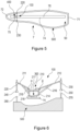
- Figure 5 schematically represents a view from above of a blade shell part comprising the spar cap and a tool for positioning the spar cap according to one example of the present disclosure.
- the tool 100 is located above the blade mould 500.
- the inner layers of the blade shell parts have not been illustrated for clarity purposes.
- the blade mould 500 may comprise a blade shell mould.
- the tool 100 is closer to the blade tip end 72 than the blade root end 71 of the wind turbine blade 7.
- the tool is located closer to the blade tip end 72, for example, in the third outermost portion (when seen from the blade root end 71) of the wind turbine blade 7 in a lengthwise direction.
- the tool 100 may be located closer to the blade root end 71 than to the blade tip end 72.
- the tool 100 may help to accurately locate the spar cap 74 in the blade mould 500.
- the connector 300 of the tool may be attached to a region of the spar cap close to the tip end 72, e.g. close to the anchor disc of a plurality of anchor discs of the spar cap closer to the tip end. Therefore, since the tool may be located closer to the blade tip end 72, a crane operator may control the lowering of the tool and the spar cap remotely from the blade root region or portion 50.
- the spar cap 74 is connected to the tool 100.
- the tool 100 and the attached spar cap 74 are moved from the position of Figure 4 to the position of Figure 5 .
- the tool and the spar cap 74 may be lifted using a crane or any other suitable lifting device when they are moved.
- the tool 100 supporting the spar cap 74 may be moved from a storage area to the blade mould with a crane.
- the first support 220 and the second support 230 of this example are arranged at both sides of the blade mould 500.
- the first support 220 and the second support 230 may be positioned at a specific location along the lengthwise direction 37.
- the spar cap 74 may thus be located at the correct lengthwise location relative to the blade mould.
- Figure 6 schematically shows an elevation view of a tool 100 for positioning a spar cap 74 in a blade mould and guiding members 260, 270 according to one example of the present disclosure.
- the tool along with the spar cap may be lifted, e.g. from a storage area, and moved towards the blade mould 500.
- the first support 220 and the second support 230 comprise a coupling portion 240, 250 configured to engage corresponding guiding members 260, 270 arranged at a trailing edge side and a leading edge side of the blade mould 500.
- the guiding members 260, 270 may form part of the blade mould 500 or may be separate from the blade mould 500.
- the guiding members 260, 270 are arranged at a specific location along the lengthwise direction.
- the spar cap 74 is attached to the connector 300 arranged between the first and the second supports 220, 230.
- the first and second supports 220, 230 may be guided by the guiding members 260, 270 while the tool supporting the spar cap 74 is lowered towards the blade mould 500.
- the tool 100 may be accurately located with respect to the blade mould 500, reducing or even avoiding the exposure of the workers to a suspended load.
- first support 220 and the second support 230 are void of coupling portions so the first and second supports may rest, for instance, on the factory floor.
- One of the coupling portion 240, 250, and the corresponding guiding member 260, 270 may comprise a funnel, and the other one may comprise a spherical center pin to be received by the funnel.
- the coupling portion 240, 250 comprises the funnel
- the corresponding guiding member 260, 270 comprises a spherical center pin.
- the guiding members 260, 270 may comprise any suitably shaped part such as a prism, cylinder, cone, and so on.
- Providing a funnel on the coupling portions 240, 250 of the supports 220, 230 and a spherical center pin on the corresponding guiding members 260, 270 enhances the guiding of the tool relative to the tool.
- the central portion 210 comprises a leading edge beam 211 extending between the connector 300 and the first support 220, and a trailing edge beam 212 extending between the connector 300 and the second support 230.
- the central portion 210 comprises a tubular configuration and can be made of a metallic material or other materials.
- the leading edge beam 211 and the trailing edge beam 212 are respectively connected to an upper end of a leading edge column 218 and to an upper end of a trailing edge column 214.
- the leading edge and the trailing edge columns 218, 214 comprise a lower end connected at opposite sides of the connector 300.
- the leading edge and the trailing edge columns 218, 214 may be arranged substantially upright with respect to the floor of the facility.
- An interconnecting beam 217 may connect the leading edge column 218 and the trailing edge column 214.
- the central portion 210 may further comprise a leading edge strut 215 extending between a central region of the leading edge beam 211 and a central region of the leading edge column 218. This leading edge strut 215 may increase the stiffness of the leading edge beam 211. Similarly, the central portion 210 may comprise a trailing edge strut 216 between the trailing edge beam 212 and the trailing edge column 214.
- the leading edge beam 211 and the trailing edge beam 212 are diagonally arranged with respect to the respective leading edge and the trailing edge columns 218, 214.
- An angle ⁇ may be defined between the leading edge beam 211 and the leading edge column 218.
- an angle ⁇ may be defined between the trailing edge beam 212 and the trailing edge column 214. Both angles ⁇ and ⁇ may be substantially the same or different from each other. In some examples, angles ⁇ and ⁇ may be greater than 90 degrees, so the spar cap 74 may be accurately arranged on the blade mould 500 despite the curve-shaped cross section of the blade mould 500.
- Figures 7A - 7B schematically illustrate a first support 220 and a second support 230 respectively in an extended position and a retracted position according to an example of the present disclosure.
- the examples of these figures have first and second supports 220, 230 telescopically configured, while the example of Figure 6 comprises first and second supports 220, 230 having a single bar.
- the first support 220 and the second support 230 comprise an upper bar 221, 231 and a lower bar 222, 232 telescopically connected to each other.
- the lower bar 222, 232 is connected to the coupling portion 240, 250.
- the lower bar 222, 232 may axially extend from the upper bar 221, 231 in the extended position as illustrated in Figure 7A , and/or the lower bar 222, 232 may be received in the interior or exterior of the upper bar 221, 231 in the retracted position as illustrated in Figure 7B .
- the first and second supports 220, 230 are in the extended position and the spar cap is raised relative to the blade mould 500. This may occur when the tool 100 and the spar cap 74 are moved towards the blade mould 500. Then, the tool 100 and the spar cap 74 are lowered relative to the blade mould 500 until the coupling portion 240, 250 and guiding members 260, 270 are brought into contact therewith. Then the tool 100 and the spar cap 74 are further lowered while the first and second supports 220, 230 are progressively retracted until the spar cap 74 rests in the blade mould 500.
- Figure 8 illustrates a perspective view of a tool for positioning a spar cap releasably attached to the spar cap according to one example of the present disclosure
- Figure 9 schematically represents an elevation view of the tool of Figure 8 in a blade mould according to one example of the present disclosure.
- tool 100 is not connected to the first spar cap reference 75 for the sake of clarity.
- the spar cap 74 has been illustrated in dotted lines for the sake of clarity.
- the connector 300 may comprise one or more vacuum cups for releasably attaching the spar cap 74, and a bracket for holding the vacuum cup.
- the connector 300 of these figures comprises a pair of vacuum devices 310 and each of the vacuum devices 310 comprises two vacuum cups 311.
- the number of vacuum cups 311 and/or vacuum devices 310 of the connector 300 may vary depending on the case.
- the vacuum cups 311 are held by the bracket 320.
- the bracket comprises a plate and two lateral webs connected to the structure 200.
- the operation of the vacuum devices 310 may be remotely controlled by e.g., the crane operator or a control unit (not shown), so as to remotely attach or de-attach the spar cap 74.
- each of the vacuum devices 310 is received in an opening 322 of the bracket 320.
- the connector 300 may comprise holding members to hold the vacuum device 310.
- the holding members may comprise screws or clamps to secure the vacuum device 310.
- the vacuum device 310 may thus be removable from bracket 320.
- the bracket 320 comprises a lower portion 321 to face the spar cap 74, wherein the lower portion 321 may comprise a curved shape.
- This curved shape may be adapted to the curvature of the blade shell 7 in the chordwise direction 38.
- the connector 300 may comprise a reference mark 330 to be aligned with a second spar cap reference 77.
- the second spar cap reference 77 may comprise a line or band along the lengthwise direction 37 of the spar cap 74.
- the reference mark 330 may comprise two opposite marks along the lengthwise direction. These opposite marks may be aligned with the second spar cap reference 77 to ensure a correct position along the chordwise direction 38.
- the reference mark 330 may comprise openings, windows, protrusions, or the like in the bracket 320 that are to be aligned with a line or points on the surface 78 of the spar cap 74.
- One of the leading edge beam 211 and the trailing edge beam 212 may be longer than the other. Therefore, connector 300 may be closer to one of the first support 220 and the second support 230 than the other. This may allow locating the spar cap 74 at the specific location in the chordwise direction when the spar cap 74 is closer to the leading edge side or the trailing edge side.
- One of the first support 220 and the second support 230 may reach a greater height than the other. This may allow locating the spar cap 74 at the specific location in the chordwise direction when the leading edge and the trailing edge of the wind turbine blade 7 have different heights from each other.
- Tool 100 may comprise a handling portion 213 for attaching to a crane or the like.
- Figure 10 schematically represents a top view of a tool for positioning a spar cap according to one example of the present disclosure.
- the tool 100 is connected to the first spar cap reference 75.
- the reference arm 400 may protrude from the central portion 210 in a direction substantially parallel to the lengthwise direction 37, in such a way that the connector 300 may be positioned at a predetermined distance 420 from the first spar cap reference 75 in the lengthwise direction 37 when the connector 300 is attached to the spar cap 74.
- the length of the reference arm 400 may be chosen depending on the sought predetermined distance 420.
- the reference arm 400 may comprise a distal end 410 configured to be inserted in a hole of the first spar cap reference 75.
- the distal end 410 may be configured to match, at least partially, the shape or configuration of the first spar cap reference 75.
- the reference arm 400 of the example of Figure 10 has an L-shaped configuration when seen from above. However, this configuration may vary depending on the position of the first spar cap reference 75 and the sought position of the connector 300 relative to the spar cap 74.
- the length and/or the configuration of the reference arm 400 may be depending on a sought specific location of the connector 300 with respect to the blade mould 500.
- the specific location of the connector 300 with respect to the blade mould 500 may depend on the location of the guiding members 260, 270 in a lengthwise direction.
- Figure 11 illustrates a side view of the tool 100 for positioning a spar cap when positioned relative to a blade mould 500 according to one example of the present disclosure.
- the central portion 210 is inclined relative to the longitudinal axis 233 of the first support 220 and the second support 230 when seen from the trailing edge side and/or the leading edge side.
- the longitudinal axis 233 of the first and second supports 220, 230 may be substantially perpendicular to the floor of the facility, e.g. the first and second supports 220, 230 may be upright.
- the central portion 210 may be connected with the first and second supports 220, 230 through flexible or rotatable joints 280 such that the central portion 210 can rotate about the joints 280 to be inclined. Therefore, an angle ⁇ may be defined between the central portion 210 and the longitudinal axis of the first and second supports 220, 230 when seen from the trailing edge side and/or the leading edge side. In some examples, the angle ⁇ may be between 2 and 10 degrees. Since the reference arm 400 may be releasably attached to the central portion 210 or the connector 300, the reference arm 400 may move with respect to the longitudinal axis of the first and second supports 220, 230 when seen from the trailing edge side and/or the leading edge side.
- the relative inclination of the central portion 210 may help to correctly attach the connector 300 and the reference arm 400 to the spar cap regardless of the curvature or inclination of the blade shell part along the lengthwise direction.
- the latter may be particularly useful when the wind turbine blade 7 includes a pre-bend configuration.
- Figure 12 is a block diagram of a method 600 for positioning a spar cap in a blade mould according to an example of the present disclosure.
- a tool 100 for positioning a spar cap 74 in a blade mould 500 according to the examples herein may be used in the method 600.
- moving the tool 100 towards the spar cap 74 to position a first support 220 and a second support 230 of the tool at respectively both sides of the spar cap is represented.
- a crane operator may move the tool 100 towards the spar cap 74 so that the first support 220 and the second support 230 are positioned at respectively both sides of the spar cap 74 with respect to the lengthwise direction.
- the method 600 further comprises engaging the reference arm 400 of the tool and the first spar cap reference 75, as represented at block 620.
- releasably attaching a connector 300 of the tool to a surface 78 of the spar cap is represented.
- the connector 300 may be releasably attached to the upper surface of the spar cap in a predetermined position along the lengthwise direction. It is not necessary to connect the first support 220 and the second support 230 with any reference part of the storage trolley.
- the method 600 further comprises moving the tool 100 towards the blade mould 500 to position the first support 220 and the second support 230 at each side of the blade mould 500, as represented at block 640.
- the first support 220 and the second support 230 are located on both sides with respect to the lengthwise direction.
- the tool 100 may be arranged in a specific location relative to the blade mould 500.
- first support 220 and the second support 230 comprise lower bars 222, 232 and upper bars 221, 231 telescopically arranged, the first and second supports 220, 230 may be in the extended position when the tool 100 is lifted to be moved to the blade mould 500.
- de-attaching the spar cap 74 from the connector 300 to arrange the spar cap 74 in the blade mould 500 is represented.
- the first support 220 and the second support 230 may comprise a coupling portion 240, 250 configured to engage corresponding guiding members 260, 270 arranged at the trailing edge side and the leading edge side of the blade mould 500.
- the method 600 comprises engaging i.e., bringing into contact, the coupling portion of first support and the second support with the corresponding guiding members.
- a funnel of any of the coupling portion 240, 250 may be brought into contact with the spherical center pin of the guiding member 260, 270.
- the method 600 may further comprise lowering the connector after the coupling portion is engaged with the corresponding guiding members. Once the engagement or contact of the coupling portion 240, 250 and guiding members 260, 270 is achieved, the connector 300 and so the tool 100 may be lowered.
- one of the coupling portion and the corresponding guiding member may comprise a funnel and the other one comprises a spherical center pin to be received by the funnel.
- the method 600 comprises inserting the spherical center pin into the funnel.
- the lower bar 222, 232 is progressively received in the interior of the upper bar 221, 231 until the retracted position is reached.
- the spar cap 74 may be positioned or rested on the blade mould 500 at a specific location after the tool 100, and so the connector 300, is lowered. The position of the spar cap 74 relative to the blade mould 500 is within the tolerances in the lengthwise direction and/or the chordwise direction. The spar cap 74 may be de-attached from the connector 300 to arrange the spar cap 74 on the blade mould 500.
- the spar cap 74 may be positioned in a storage trolley when tool 100 is moving towards the spar cap 74.
- the spar cap 74 may be provided on a storage trolley (not illustrated) or the like in a storage area.
- the spar cap 74 may be manufactured in the same facility as the blade mould 500 or outside the facility.
- the reference arm 400 may be engaged with the first spar cap reference 75 when the tool 100 moves towards the blade mould 500.
- the tool 100 and the spar cap 74 may be lifted by the crane. Therefore, a relative movement of the connector 300 and the spar cap 74 at least along the lengthwise direction may be avoided or at least reduced while the tool 100 and the spar cap 74 are moved and lifted.
- the method 600 may further comprise inserting the distal end 410 of the reference arm 400 in a hole of the first spar cap reference 75.
- the method 600 may comprise removing the reference arm 400 from the tool when the spar cap 74 is arranged on the blade mould 500.
- the reference arm 400 may be removed when the spar cap 74 is correctly located on the blade mould 500.
- the connector 300 may comprise a reference mark 330 to be aligned with a second spar cap reference 77.
- the method 600 comprises aligning the reference mark 330 with the second spar cap reference 77.
- the central portion 210 may be connected with the first and second supports 220, 230 through flexible or rotatable joints 280 such that the central portion 210 can rotate about the joints 280 to be inclined.
- the method 600 comprises rotating the central portion 210 about the joints 280 to incline the central portion 210 with respect to the longitudinal axis of the first and second supports 220, 230 when seen from the trailing edge side and/or the leading edge side. This rotation may be performed when the spar cap 74 is positioned on the blade mould 500. This way, the spar cap 74 may be adapted to the pre-bend of the wind turbine blade 7 when the spar cap is arranged on blade mould 500.
Landscapes
- Engineering & Computer Science (AREA)
- Mechanical Engineering (AREA)
- Chemical & Material Sciences (AREA)
- Composite Materials (AREA)
- Wind Motors (AREA)
Abstract
Description
- The present disclosure relates to tools for positioning spar caps in blade moulds, and methods for positioning spar caps in blade moulds.
- Modern wind turbines are commonly used to supply electricity to the electrical grid. Wind turbines of this kind generally comprise a rotor with a rotor hub and a plurality of wind turbine blades. The rotor is set into rotation under the influence of the wind on the blades. The rotation of the rotor shaft drives the generator rotor either directly ("directly driven") or through the use of a gearbox. The gearbox (if present), the generator, and other systems are usually mounted in a nacelle on top of a wind turbine tower.
- Wind turbine blades are generally made from fiber-reinforced polymers or plastics (FRP's), which are composite materials comprising a polymer matrix and reinforced with fibers. The fibers are usually glass or carbon and provide longitudinal stiffness and strength.
- Wind turbine blades are commonly manufactured by joining two blade shell parts made from fiber-reinforced polymers, e.g. glass or carbon fiber reinforced polymers. These blade shell parts may be molded using a resin infusion technology or a prepreg technology. In resin infusion technology, fibers are placed in a blade mould and then, the resin is injected into the mould cavity under pressure. This resin fills the volume between the cavity, and then, the resin is cured or hardened. Examples of resin infusion technology may be Resin Transfer Molding (RTM) or Vacuum Assisted Resin Transfer Molding (VARTM). In VARTM, the resin is injected under a vacuum or pressure lower than atmospheric.
- A load-carrying structure may be arranged between the pressure side blade shell part and the suction side blade shell part. The load-carrying structure may comprise a reinforcing structure joined to opposing spar caps of the respective blade shell part. The spar caps may be embedded within the composite laminate materials of the blade shell parts or laminated to an inner surface of the blade shell. The spar caps are used to receive the reinforcing structure, e.g. a pair of opposing flanges, and to structurally reinforce the wind turbine blade. The spar caps provided in the blade shell parts typically increase the stiffness, buckling resistance, and strength of the wind turbine blade. The spar caps extend along a longitudinal length of the wind turbine blade.
- Spar caps may be constructed of various materials, including glass fiber laminate composites and carbon fiber laminate composites.
- The spar caps are usually manufactured in a spar cap mould, and then, are arranged on the fibers placed in the blade mould. A crane is generally used for lifting and positioning the pre-fabricated spar caps on the blade mould.
- The spar cap must be placed in the blade mould at a specific location along both the lengthwise direction and the chordwise direction. Furthermore, the spar caps must be positioned within predetermined tolerances to guarantee the blade shell's mechanical properties. However, as the spar caps are long structures, the spar caps may be easily misaligned relative to the specific location. This may provide a manufacturing process with poor repeatability. A spar cap misaligned relative to the blade shell part could cause the blade shell to be disregarded since the mechanical properties of the blade shell part may be negatively affected. This may cause material wastage.
- One crane operator and several workers distributed along the lengthwise direction of the blade mould may be required to accurately position the spar cap at the specific location. Accordingly, accurately positioning the spar cap may be complex and labor-intensive. The workers may guide the spar cap towards the specific location. This may involve the workers being exposed to a suspended load. Working under a suspended load puts the safety of the workers at risk.
- The present disclosure provides examples of tools and methods that at least partially resolve some of the aforementioned disadvantages.
- In a first aspect, a tool for positioning a spar cap in a blade mould is provided. The tool comprises a structure comprising a central portion, a first support, and a second support configured to be positioned at respectively both sides of the spar cap with respect to a lengthwise direction. The central portion is arranged between the first support and the second support.
- The tool further comprises a connector arranged at the central portion, wherein the connector is configured to be releasably attached to a surface of the spar cap, and a reference arm configured to engage a first spar cap reference for positioning the connector relative to the surface of the spar cap.
- According to this aspect, the connector may be releasably attached to the spar cap while the reference arm engages the first spar cap reference. Therefore, the connector may be accurately positioned with respect to the spar cap in a predetermined position in the lengthwise direction and/or a chordwise direction. This may help to position the spar cap on the blade mould within predetermined tolerances in the lengthwise direction and/or chordwise direction at a specific location.
- As the spar cap may be positioned in the blade mould within predetermined tolerances, the mechanical properties of the manufactured blade shells may be guaranteed. Furthermore, the number of disregarded blade shells may be reduced. As a consequence, material wastage may be avoided or at least reduced.
- Moreover, since the connector may be releasably attached to the spar caps at the same predetermined position time after time, the repeatability of the manufacturing process may be enhanced.
- Furthermore, the first spar cap reference is used for accurately positioning and attaching the connector to the spar cap. This may allow for accurately positioning the connector with respect to the spar cap regardless of the place where the spar cap is stored. Accordingly, it is not necessary to provide reference features in carriage tools storage trolleys or spar cap moulds. This may simplify the manufacturing process and the manufacturing tools.
- In a further aspect, a method for positioning a spar cap in a blade mould using a tool for positioning a spar cap in a blade mould is provided. The method comprises moving the tool towards the spar cap to position a first support and a second support of the tool at respectively both sides of the spar cap.
- The method further comprises engaging a reference arm of the tool and a first spar cap reference, and releasably attaching a connector of the tool to a surface of the spar cap.
- In addition, the method comprises moving the tool towards the blade mould to position the first support and the second support at each side of the blade mould, and de-attaching the spar cap from the connector to arrange the spar cap in the blade mould.
- Advantages derived from this aspect may be similar to those mentioned regarding the first aspect.
- Non-limiting examples of the present disclosure will be described in the following, with reference to the appended drawings, in which:
-
Figure 1 illustrates a perspective view of a wind turbine according to one example; -
Figure 2 shows a perspective view of a blade root portion of a wind turbine blade according to one example of the present disclosure; -
Figure 3 shows a cross-sectional view of a wind turbine blade according to one example of the present disclosure; -
Figure 4 schematically shows a perspective view of a tool for positioning a spar cap in a blade mould according to one example of the present disclosure; -
Figure 5 schematically represents a view from above of a blade mould comprising the spar cap and a tool for positioning the spar cap according to one example of the present disclosure; -
Figure 6 schematically shows an elevation view of a tool for positioning a spar cap in a blade mould and guide members according to one example of the present disclosure; -
Figures 7A - 7B schematically illustrate a first support and a second support respectively in an extended position and a retracted position according to an example of the present disclosure; -
Figure 8 illustrates a perspective view of a tool for positioning a spar cap releasably attached to the spar cap according to one example of the present disclosure; -
Figure 9 schematically represents an elevation view of the tool ofFigure 8 in a blade mould according to one example of the present disclosure; -
Figure 10 schematically represents a top view of a tool for positioning a spar cap according to one example of the present disclosure; -
Figure 11 illustrates a side view of the tool for positioning a spar cap when positioned relative to a blade mould according to one example of the present disclosure; and -
Figure 12 is a block diagram of a method for positioning a spar cap in a blade mould according to an example of the present disclosure. - In these figures, the same reference signs have been used to designate matching elements.
-
Figure 1 illustrates a perspective view of one example of awind turbine 1. As shown, thewind turbine 1 includes atower 2 extending from asupport surface 3, a nacelle 4 mounted on thetower 2, and arotor 5 coupled to the nacelle 4. Therotor 5 includes arotatable hub 6 and at least onewind turbine blade 7 coupled to and extending outwardly from therotor hub 6. For example, in the illustrated example, therotor 5 includes threewind turbine blades 7. However, in other examples, therotor 5 may include more or less than threewind turbine blades 7. Eachwind turbine blade 7 may be spaced from therotor hub 6 to facilitate rotating therotor 5 to enable kinetic energy to be transferred from the wind into usable mechanical energy, and subsequently, electrical energy. For instance, therotor hub 6 may be rotatably coupled to an electric generator 10 positioned within the nacelle 4 or forming part of the nacelle to permit electrical energy to be produced. -
Figure 2 shows a perspective view of a blade root portion of awind turbine blade 7 according to one example of the present disclosure. Thewind turbine blade 7 extends in a longitudinal direction, spanwise direction, orlengthwise direction 37 from ablade root end 71 to ablade tip end 72. Thewind turbine blade 7 comprises a blade root region orportion 50 closest to the rotor hub, a profiled or anairfoil portion 52 furthest away from the rotor hub and atransition portion 51 between theblade root portion 50 and theairfoil portion 52. Thewind turbine blade 7 comprises aleading edge 53 facing the direction of rotation of thewind turbine blade 7 when mounted on the rotor hub, and a trailingedge 54 facing the opposite direction of the leadingedge 53. - The
wind turbine blade 7 comprises ablade shell 73. Theblade shell 73 comprises an outer side or surface that defines the external shape of the blade, e.g. the outer shape at the blade root portion and the outer shape at the airfoil portion. Theblade shell 73 also comprises an inner side or surface that defines the internal volume of the blade and faces a load-carrying structure. Theblade shell 73 may be made of fiber-reinforced polymer or plastics, e.g. glass fiber and/or carbon fiber. - The blade shell may be formed by a plurality of blade shell parts. The plurality of blade shell parts may be joined together to form the blade shell. The blade shell parts may be formed and then joined according to any of the examples herein disclosed. Resin infusion technology, e.g. RTM or VARTM, or prepreg technology may be used for manufacturing the blade shell parts.
-
Figure 3 shows a cross-sectional view of the wind turbine blade according to one example of the present disclosure. Asuction side 57 or downwind side, and apressure side 56 or upwind side extend from the leadingedge 53 to the trailingedge 54. Thewind turbine blade 7 further comprises achord line 38 between theleading edge 53 and the trailingedge 54. Thechord line 38 extends in an edgewise direction or chordwise direction. Aflapwise direction 39 is substantially perpendicular to the chord line orchordwise direction 38. - In this example, the blade shell comprises a lower side
blade shell part 58 and an upper sideblade shell part 59. The lower sideblade shell part 58 may be a pressure side blade shell part. The upper sideblade shell part 59 may be a suction side blade shell part. The lower sideblade shell part 58 may be joined to the upper sideblade shell part 59 along joining lines along the leadingedge 53 and the trailingedge 54. Each of theseblade shell parts wind turbine blade 7. A reinforcing structure is arranged between the lower sideblade shell part 58 and the upper sideblade shell part 59. - The
wind turbine blade 7 comprises a blade structure that provides stiffness to the wind turbine blade. The blade structure of this example comprises theblade shell 73 and a load-carrying structure. In further examples, the blade structure may also comprise a plurality of structural ribs arranged along the length of the blade. In this example, the load-carrying structure comprises ashear web 43. The load-carrying structure of this figure also comprises a pressure side spar cap 74 arranged at thepressure side 56 and a suction side spar cap 76 at thesuction side 57. - Although the examples of the present description are related to the pressure side spar cap 74 (
spar cap 74 from now on), the expression spar cap may refer to both the pressure side spar cap and the suction side spar cap. Thespar cap 74 is embedded between the outer and the inner layer of a blade shell part. In some examples, theshear web 43 could be a spar box with spar sides, such as a trailing edge spar side and a leading edge spar side. -
Figure 4 schematically shows a perspective view of atool 100 for positioning aspar cap 74 in a blade mould according to one example of the present disclosure. Thetool 100 comprises astructure 200, aconnector 300, and areference arm 400. Thespar cap 74 inFigure 4 may be provided on a storage trolley (not illustrated) or the like in a storage area. InFigure 4 , thespar cap 74 has been illustrated in dotted lines for the sake of clarity. - The
structure 200 comprises acentral portion 210 arranged between afirst support 220 and asecond support 230. Thefirst support 220 and thesecond support 230 are configured to be positioned at respectively both sides of thespar cap 74 with respect to thelengthwise direction 37. Thecentral portion 210 may comprise a generally planar configuration. Therefore,structure 200 may be positioned substantially perpendicular to the length of thespar cap 74 when thefirst support 220 and thesecond support 230 are positioned at respectively both sides of thespar cap 74. Thestructure 200 of this example extends in a direction substantially parallel to thechordwise direction 38. - In some examples, the
first support 220 may comprise a leading edge support. Thesecond support 230 may comprise a trailing edge support. - The
connector 300 is arranged at thecentral portion 210 and is configured to be releasably attached to asurface 78 of thespar cap 74, for instance, a spar cap upper surface. Theconnector 300 may be based on a technology that allows releasably attaching thesurface 78, e.g., vacuum, adhesion, or the like. - The
reference arm 400 is configured to engage a firstspar cap reference 75 for positioning theconnector 300 relative to thesurface 78 of thespar cap 74. Thereference arm 400 may engage the firstspar cap reference 75. Then, theconnector 300 may be attached to thesurface 78 of thespar cap 74 at the predetermined position. - The
reference arm 400 may be releasably attached to the rest of thetool 100. This may allow using thereference arm 400 to maintain theconnector 300 at the predetermined position in the lengthwise direction of the spar cap during positioning operations of the spar cap, and remove thereference arm 400, for instance, when thespar cap 74 is already suitably located in the blade mould. In this example, thereference arm 400 extends or protrudes from thestructure 200 and/or theconnector 300 in a direction substantially parallel to thelengthwise direction 37. This way, the reference arm does not interfere with theconnector 300. - In some examples, the first
spar cap reference 75 may comprise an anchor disc of a lightning protection system of thewind turbine blade 7. The anchor disc may be a component of a lightning protection system of thewind turbine blade 7. The anchor disc may be used for connecting electrically conductive elements of the spar cap to a down conductor. The spar cap may comprise a plurality of anchor discs distributed along the spanwise direction. Electrical connectors may be connected to these anchor discs to electrically connect the spar cap, e.g carbon fibres of the spar cap, to the down conductor of thewind turbine blade 7. Each of these anchor discs is arranged at a specific position along the spanwise direction of the spar cap to ensure a proper connection to the remaining components of the lightning protection system. - In some examples, the first
spar cap reference 75 may comprise the anchor disc of the spar cap closer to the tip end of the wind turbine blade. Each of the anchor discs is associated with a predetermined position along the length of the spar cap. - In other examples, the first
spar cap reference 75 may comprise any other feature of thespar cap 74 such as bores, cavities, depressions, indentations and/or protuberances associated with a predetermined position along the lengthwise direction of thespar cap 74. Theconnector 300 may be attached to thespar cap 74 at any predetermined position along the length of the spar cap depending on the position of the firstspar cap reference 75. -
Figure 5 schematically represents a view from above of a blade shell part comprising the spar cap and a tool for positioning the spar cap according to one example of the present disclosure. - In this figure, the
tool 100 is located above theblade mould 500. In the blade moulds of the examples disclosed herein, the inner layers of the blade shell parts have not been illustrated for clarity purposes. - In some examples, the
blade mould 500 may comprise a blade shell mould. - In this example, the
tool 100 is closer to theblade tip end 72 than theblade root end 71 of thewind turbine blade 7. The tool is located closer to theblade tip end 72, for example, in the third outermost portion (when seen from the blade root end 71) of thewind turbine blade 7 in a lengthwise direction. However, in some examples, thetool 100 may be located closer to theblade root end 71 than to theblade tip end 72. - The
tool 100 may help to accurately locate thespar cap 74 in theblade mould 500. Theconnector 300 of the tool may be attached to a region of the spar cap close to thetip end 72, e.g. close to the anchor disc of a plurality of anchor discs of the spar cap closer to the tip end. Therefore, since the tool may be located closer to theblade tip end 72, a crane operator may control the lowering of the tool and the spar cap remotely from the blade root region orportion 50. - In this figure, the
spar cap 74 is connected to thetool 100. Thetool 100 and the attachedspar cap 74 are moved from the position ofFigure 4 to the position ofFigure 5 . The tool and thespar cap 74 may be lifted using a crane or any other suitable lifting device when they are moved. For example, thetool 100 supporting thespar cap 74 may be moved from a storage area to the blade mould with a crane. - The
first support 220 and thesecond support 230 of this example are arranged at both sides of theblade mould 500. Thefirst support 220 and thesecond support 230 may be positioned at a specific location along thelengthwise direction 37. Thespar cap 74 may thus be located at the correct lengthwise location relative to the blade mould. -
Figure 6 schematically shows an elevation view of atool 100 for positioning aspar cap 74 in a blade mould and guidingmembers blade mould 500. - In the
tool 100 of this figure, thefirst support 220 and thesecond support 230 comprise acoupling portion members blade mould 500. The guidingmembers blade mould 500 or may be separate from theblade mould 500. The guidingmembers - The
spar cap 74 is attached to theconnector 300 arranged between the first and thesecond supports second supports members spar cap 74 is lowered towards theblade mould 500. Thus, thetool 100 may be accurately located with respect to theblade mould 500, reducing or even avoiding the exposure of the workers to a suspended load. - In some non-illustrated examples, the
first support 220 and thesecond support 230 are void of coupling portions so the first and second supports may rest, for instance, on the factory floor. - One of the
coupling portion member Figure 6 , thecoupling portion member members - Providing a funnel on the
coupling portions supports members - As can be seen in
Figure 6 , thecentral portion 210 comprises aleading edge beam 211 extending between theconnector 300 and thefirst support 220, and a trailingedge beam 212 extending between theconnector 300 and thesecond support 230. Thecentral portion 210 comprises a tubular configuration and can be made of a metallic material or other materials. Theleading edge beam 211 and the trailingedge beam 212 are respectively connected to an upper end of aleading edge column 218 and to an upper end of a trailingedge column 214. The leading edge and the trailingedge columns connector 300. The leading edge and the trailingedge columns interconnecting beam 217 may connect theleading edge column 218 and the trailingedge column 214. - The
central portion 210 may further comprise aleading edge strut 215 extending between a central region of theleading edge beam 211 and a central region of theleading edge column 218. Thisleading edge strut 215 may increase the stiffness of theleading edge beam 211. Similarly, thecentral portion 210 may comprise a trailingedge strut 216 between the trailingedge beam 212 and the trailingedge column 214. - The
leading edge beam 211 and the trailingedge beam 212 are diagonally arranged with respect to the respective leading edge and the trailingedge columns leading edge beam 211 and theleading edge column 218. Similarly, an angle β may be defined between the trailingedge beam 212 and the trailingedge column 214. Both angles α and β may be substantially the same or different from each other. In some examples, angles α and β may be greater than 90 degrees, so thespar cap 74 may be accurately arranged on theblade mould 500 despite the curve-shaped cross section of theblade mould 500. -
Figures 7A - 7B schematically illustrate afirst support 220 and asecond support 230 respectively in an extended position and a retracted position according to an example of the present disclosure. The examples of these figures have first andsecond supports Figure 6 comprises first andsecond supports - In the example of this
Figures 7A - 7B , thefirst support 220 and thesecond support 230 comprise anupper bar lower bar lower bar coupling portion lower bar upper bar Figure 7A , and/or thelower bar upper bar Figure 7B . - In the example of
Figure 7A , the first andsecond supports blade mould 500. This may occur when thetool 100 and thespar cap 74 are moved towards theblade mould 500. Then, thetool 100 and thespar cap 74 are lowered relative to theblade mould 500 until thecoupling portion members tool 100 and thespar cap 74 are further lowered while the first andsecond supports spar cap 74 rests in theblade mould 500. In the example ofFigure 7B , it can be seen that the first andsecond supports blade mould 500. Therefore, a smooth lowering movement and location of the spar cap relative to theblade mould 500 may be achieved. A downwards movement of thetool 100 and thespar cap 74 may be precisely controlled. -
Figure 8 illustrates a perspective view of a tool for positioning a spar cap releasably attached to the spar cap according to one example of the present disclosure, andFigure 9 schematically represents an elevation view of the tool ofFigure 8 in a blade mould according to one example of the present disclosure. In the examples ofFigures 8 and 9 ,tool 100 is not connected to the firstspar cap reference 75 for the sake of clarity. Furthermore, inFigure 8 thespar cap 74 has been illustrated in dotted lines for the sake of clarity. - The
connector 300 may comprise one or more vacuum cups for releasably attaching thespar cap 74, and a bracket for holding the vacuum cup. Theconnector 300 of these figures comprises a pair ofvacuum devices 310 and each of thevacuum devices 310 comprises twovacuum cups 311. The number ofvacuum cups 311 and/orvacuum devices 310 of theconnector 300 may vary depending on the case. The vacuum cups 311 are held by thebracket 320. In this example, the bracket comprises a plate and two lateral webs connected to thestructure 200. - The operation of the
vacuum devices 310 may be remotely controlled by e.g., the crane operator or a control unit (not shown), so as to remotely attach or de-attach thespar cap 74. - In these figures, each of the
vacuum devices 310 is received in anopening 322 of thebracket 320. Theconnector 300 may comprise holding members to hold thevacuum device 310. The holding members may comprise screws or clamps to secure thevacuum device 310. Thevacuum device 310 may thus be removable frombracket 320. - In the example of these figures, the
bracket 320 comprises alower portion 321 to face thespar cap 74, wherein thelower portion 321 may comprise a curved shape. This curved shape may be adapted to the curvature of theblade shell 7 in thechordwise direction 38. - The
connector 300 may comprise areference mark 330 to be aligned with a secondspar cap reference 77. The secondspar cap reference 77 may comprise a line or band along thelengthwise direction 37 of thespar cap 74. In some examples, thereference mark 330 may comprise two opposite marks along the lengthwise direction. These opposite marks may be aligned with the secondspar cap reference 77 to ensure a correct position along thechordwise direction 38. In other examples, thereference mark 330 may comprise openings, windows, protrusions, or the like in thebracket 320 that are to be aligned with a line or points on thesurface 78 of thespar cap 74. - One of the
leading edge beam 211 and the trailingedge beam 212 may be longer than the other. Therefore,connector 300 may be closer to one of thefirst support 220 and thesecond support 230 than the other. This may allow locating thespar cap 74 at the specific location in the chordwise direction when thespar cap 74 is closer to the leading edge side or the trailing edge side. - One of the
first support 220 and thesecond support 230 may reach a greater height than the other. This may allow locating thespar cap 74 at the specific location in the chordwise direction when the leading edge and the trailing edge of thewind turbine blade 7 have different heights from each other. -
Tool 100 may comprise ahandling portion 213 for attaching to a crane or the like. -
Figure 10 schematically represents a top view of a tool for positioning a spar cap according to one example of the present disclosure. In the example ofFigure 10 , thetool 100 is connected to the firstspar cap reference 75. - The
reference arm 400 may protrude from thecentral portion 210 in a direction substantially parallel to thelengthwise direction 37, in such a way that theconnector 300 may be positioned at apredetermined distance 420 from the firstspar cap reference 75 in thelengthwise direction 37 when theconnector 300 is attached to thespar cap 74. The length of thereference arm 400 may be chosen depending on the soughtpredetermined distance 420. - The
reference arm 400 may comprise adistal end 410 configured to be inserted in a hole of the firstspar cap reference 75. In some examples, thedistal end 410 may be configured to match, at least partially, the shape or configuration of the firstspar cap reference 75. - The
reference arm 400 of the example ofFigure 10 has an L-shaped configuration when seen from above. However, this configuration may vary depending on the position of the firstspar cap reference 75 and the sought position of theconnector 300 relative to thespar cap 74. - In some examples, the length and/or the configuration of the
reference arm 400 may be depending on a sought specific location of theconnector 300 with respect to theblade mould 500. The specific location of theconnector 300 with respect to theblade mould 500 may depend on the location of the guidingmembers -
Figure 11 illustrates a side view of thetool 100 for positioning a spar cap when positioned relative to ablade mould 500 according to one example of the present disclosure. In the example of this Figure, thecentral portion 210 is inclined relative to thelongitudinal axis 233 of thefirst support 220 and thesecond support 230 when seen from the trailing edge side and/or the leading edge side. Thelongitudinal axis 233 of the first andsecond supports second supports - The
central portion 210 may be connected with the first andsecond supports rotatable joints 280 such that thecentral portion 210 can rotate about thejoints 280 to be inclined. Therefore, an angle γ may be defined between thecentral portion 210 and the longitudinal axis of the first andsecond supports reference arm 400 may be releasably attached to thecentral portion 210 or theconnector 300, thereference arm 400 may move with respect to the longitudinal axis of the first andsecond supports - The relative inclination of the
central portion 210 may help to correctly attach theconnector 300 and thereference arm 400 to the spar cap regardless of the curvature or inclination of the blade shell part along the lengthwise direction. The latter may be particularly useful when thewind turbine blade 7 includes a pre-bend configuration. -
Figure 12 is a block diagram of amethod 600 for positioning a spar cap in a blade mould according to an example of the present disclosure. Atool 100 for positioning aspar cap 74 in ablade mould 500 according to the examples herein may be used in themethod 600. - At
block 610, moving thetool 100 towards thespar cap 74 to position afirst support 220 and asecond support 230 of the tool at respectively both sides of the spar cap, is represented. A crane operator may move thetool 100 towards thespar cap 74 so that thefirst support 220 and thesecond support 230 are positioned at respectively both sides of thespar cap 74 with respect to the lengthwise direction. - The
method 600 further comprises engaging thereference arm 400 of the tool and the firstspar cap reference 75, as represented atblock 620. - At
block 630, releasably attaching aconnector 300 of the tool to asurface 78 of the spar cap is represented. Theconnector 300 may be releasably attached to the upper surface of the spar cap in a predetermined position along the lengthwise direction. It is not necessary to connect thefirst support 220 and thesecond support 230 with any reference part of the storage trolley. - The
method 600 further comprises moving thetool 100 towards theblade mould 500 to position thefirst support 220 and thesecond support 230 at each side of theblade mould 500, as represented atblock 640. Thefirst support 220 and thesecond support 230 are located on both sides with respect to the lengthwise direction. Thetool 100 may be arranged in a specific location relative to theblade mould 500. - If the
first support 220 and thesecond support 230 compriselower bars upper bars second supports tool 100 is lifted to be moved to theblade mould 500. - At
block 650, de-attaching thespar cap 74 from theconnector 300 to arrange thespar cap 74 in theblade mould 500 is represented. - In some examples, the
first support 220 and thesecond support 230 may comprise acoupling portion members blade mould 500. In those examples, themethod 600 comprises engaging i.e., bringing into contact, the coupling portion of first support and the second support with the corresponding guiding members. For instance, a funnel of any of thecoupling portion member - The
method 600 may further comprise lowering the connector after the coupling portion is engaged with the corresponding guiding members. Once the engagement or contact of thecoupling portion members connector 300 and so thetool 100 may be lowered. - In some examples, one of the coupling portion and the corresponding guiding member may comprise a funnel and the other one comprises a spherical center pin to be received by the funnel. In those examples, the
method 600 comprises inserting the spherical center pin into the funnel. - As the
tool 100 is lowered, thelower bar upper bar - The
spar cap 74 may be positioned or rested on theblade mould 500 at a specific location after thetool 100, and so theconnector 300, is lowered. The position of thespar cap 74 relative to theblade mould 500 is within the tolerances in the lengthwise direction and/or the chordwise direction. Thespar cap 74 may be de-attached from theconnector 300 to arrange thespar cap 74 on theblade mould 500. - According to some examples of
method 600, thespar cap 74 may be positioned in a storage trolley whentool 100 is moving towards thespar cap 74. Thespar cap 74 may be provided on a storage trolley (not illustrated) or the like in a storage area. Thespar cap 74 may be manufactured in the same facility as theblade mould 500 or outside the facility. - The
reference arm 400 may be engaged with the firstspar cap reference 75 when thetool 100 moves towards theblade mould 500. Thetool 100 and thespar cap 74 may be lifted by the crane. Therefore, a relative movement of theconnector 300 and thespar cap 74 at least along the lengthwise direction may be avoided or at least reduced while thetool 100 and thespar cap 74 are moved and lifted. - The
method 600 may further comprise inserting thedistal end 410 of thereference arm 400 in a hole of the firstspar cap reference 75. - The
method 600 may comprise removing thereference arm 400 from the tool when thespar cap 74 is arranged on theblade mould 500. Thereference arm 400 may be removed when thespar cap 74 is correctly located on theblade mould 500. - In some examples, the
connector 300 may comprise areference mark 330 to be aligned with a secondspar cap reference 77. In those examples, themethod 600 comprises aligning thereference mark 330 with the secondspar cap reference 77. - In some examples, the
central portion 210 may be connected with the first andsecond supports rotatable joints 280 such that thecentral portion 210 can rotate about thejoints 280 to be inclined. In those examples, themethod 600 comprises rotating thecentral portion 210 about thejoints 280 to incline thecentral portion 210 with respect to the longitudinal axis of the first andsecond supports spar cap 74 is positioned on theblade mould 500. This way, thespar cap 74 may be adapted to the pre-bend of thewind turbine blade 7 when the spar cap is arranged onblade mould 500. - For reasons of completeness, various aspects of the present disclosure are set out in the following numbered clauses:
- Clause 1: A tool for positioning a spar cap in a blade mould, wherein the tool comprises:
- a structure comprising:
- a central portion;
- a first support and a second support configured to be positioned at respectively both sides of the spar cap with respect to a lengthwise direction;
- a connector arranged at the central portion, wherein the connector is configured to be releasably attached to a surface of the spar cap;
- a reference arm configured to engage a first spar cap reference for positioning the connector relative to the surface of the spar cap.
- a structure comprising:
- Clause 2: The tool according to
clause 1, wherein the first support and the second support comprise a coupling portion configured to engage corresponding guiding members arranged at a trailing edge side and a leading edge side of the blade mould. - Clause 3: The tool according to
clause 2, wherein one of the coupling portion and the corresponding guiding member comprises a funnel and the other one comprises a spherical center pin to be received by the funnel. - Clause 4: The tool according to any of clauses 2-3, wherein the coupling portion comprises a funnel and the corresponding guiding member comprises a spherical center pin.
- Clause 5: The tool according to any of clauses 2-4, wherein the first support and the second support comprise an upper bar and a lower bar telescopically connected to each other, wherein the lower bar is connected to the coupling portion.
- Clause 6: The tool according to any of clauses 1 - 5, wherein the connector comprises:
- one or more vacuum cups for releasably attaching the spar cap;
- a bracket for holding the one or more vacuum cups.
- Clause 7: The tool according to
clause 6, wherein the bracket comprises a lower portion to face the spar cap, wherein the lower portion comprises a curved shape. - Clause 8: The tool according to any of clauses 1 - 7, wherein the first spar cap reference comprises an anchor disc of a lightning protection system.
- Clause 9: The tool according to any of clauses 1 - 8, wherein the connector comprises a reference mark to be aligned with a second spar cap reference.
- Clause 10: The tool according to clause 9, wherein the second spar cap reference comprises a line along the lengthwise direction of the spar cap.
- Clause 11: The tool according to any of clauses 1 - 10, wherein the central portion comprises:
- a leading edge beam extending between the connector and the first support, and
- a trailing edge beam extending between the connector and the second support.
- Clause 12: The tool according to any of clauses 1 - 11, wherein the reference arm protrudes from the central portion in a direction substantially parallel to the lengthwise direction, in such a way that the connector is positioned in a predetermined distance from the first spar cap reference in the lengthwise direction when the connector is attached to the spar cap.
- Clause 13: The tool according to any of clauses 1 - 12, wherein the reference arm comprises a distal end configured to be inserted in a hole of the first spar cap reference.
- Clause 14: A method for positioning a spar cap in a blade mould using a tool for positioning a spar cap in a blade mould, wherein the method comprises:
- moving the tool towards the spar cap to position a first support and a second support of the tool at respectively both sides of the spar cap;
- engaging a reference arm of the tool and a first spar cap reference;
- releasably attaching a connector of the tool to a surface of the spar cap;
- moving the tool towards the blade mould to position the first support and the second support at each side of the blade mould;
- de-attaching the spar cap from the connector to arrange the spar cap in the blade mould.
- Clause 15: The method according to clause 14, wherein the first support and the second support comprise a coupling portion configured to engage corresponding guiding members arranged at a trailing edge side and a leading edge side of the blade mould, the method comprising engaging the coupling portion of first support and the second support with the corresponding guiding members.
- Clause 16: The method according to clause 15, comprising lowering the connector after the coupling portion is engaged with the corresponding guiding members.
- Clause 17: The method according to any of clauses 15 - 16, wherein one of the coupling portion and the corresponding guiding member comprises a funnel and the other one comprises a spherical center pin to be received by the funnel, the method comprising inserting the spherical center pin into the funnel.
- Clause 18: The method according to any of clauses 14 - 17, wherein the spar cap is positioned in a storage trolley when the tool is moving towards the spar cap.
- Clause 19: The method according to any of clauses 14 - 18, wherein the reference arm is engaged with the first spar cap reference when the tool moves towards the blade mould.
- Clause 20: The method according to any of clauses 14 - 19, wherein the connector comprises a reference mark to be aligned with a second spar cap reference, the method comprising aligning the reference mark with the second spar cap reference.
- This written description uses examples to disclose the invention, including the preferred embodiments, and also to enable any person skilled in the art to practice the invention, including making and using any devices or systems and performing any incorporated methods. The patentable scope of the invention is defined by the claims, and may include other examples that occur to those skilled in the art. Such other examples are intended to be within the scope of the claims if they have structural elements that do not differ from the literal language of the claims, or if they include equivalent structural elements with insubstantial differences from the literal languages of the claims. Aspects from the various embodiments described, as well as other known equivalents for each such aspects, can be mixed and matched by one of ordinary skill in the art to construct additional embodiments and techniques in accordance with principles of this application. If reference signs related to drawings are placed in parentheses in a claim, they are solely for attempting to increase the intelligibility of the claim, and shall not be construed as limiting the scope of the claim.
Claims (15)
- A tool (100) for positioning a spar cap (74) in a blade mould (500), wherein the tool comprises:- a structure (200) comprising:- a central portion (210);- a first support (220) and a second support (230) configured to be positioned at respectively both sides of the spar cap with respect to a lengthwise direction;wherein the central portion is arranged between the first support and the second support;- a connector (300) arranged at the central portion, wherein the connector is configured to be releasably attached to a surface (78) of the spar cap;- a reference arm (400) configured to engage a first spar cap reference (75) for positioning the connector relative to the surface of the spar cap.
- The tool according to claim 1, wherein the first support (220) and the second support (230) comprise a coupling portion (240, 250) configured to engage corresponding guiding members (260, 270) arranged at a trailing edge side and a leading edge side of the blade mould (500).
- The tool according to claim 2, wherein one of the coupling portion (240, 250) and the corresponding guiding member (260, 270) comprises a funnel and the other one comprises a spherical center pin to be received by the funnel.
- The tool according to any of claims 2-3, wherein the coupling portion (240, 250) comprises a funnel and the corresponding guiding member (260, 270) comprises a spherical center pin.
- The tool according to any of claims 2-4, wherein the first support (220) and the second support (230) comprise an upper bar (221, 231) and a lower bar (222, 232) telescopically connected to each other, wherein the lower bar (222, 232) is connected to the coupling portion (240, 250).
- The tool according to any of claims 1-5, wherein the connector (300) comprises:- one or more vacuum cups (311) for releasably attaching the spar cap (74);- a bracket (320) for holding the one or more vacuum cups (311).
- The tool according to any of claims 1-6, wherein the first spar cap reference (75) comprises an anchor disc of a lightning protection system.
- The tool according to any of claims 1 - 7, wherein the connector (300) comprises a reference mark (330) to be aligned with a second spar cap reference (77).
- The tool according to any of claims 1 - 8, wherein the reference arm (400) protrudes from the central portion (210) in a direction substantially parallel to the lengthwise direction, in such a way that the connector (300) is positioned in a predetermined distance from the first spar cap reference (75) in the lengthwise direction when the connector is attached to the spar cap.
- The tool according to any of claims 1 - 9, wherein the reference arm (400) comprises a distal end (410) configured to be inserted in a hole of the first spar cap reference (75).
- A method (600) for positioning a spar cap in a blade mould using a tool for positioning a spar cap in a blade mould, wherein the method comprises:- moving (610) the tool towards the spar cap to position a first support and a second support of the tool at respectively both sides of the spar cap;- engaging (620) a reference arm of the tool and a first spar cap reference;- releasably (630) attaching a connector of the tool to a surface of the spar cap;- moving (640) the tool towards the blade mould to position the first support and the second support at each side of the blade mould;- de-attaching (650) the spar cap from the connector to arrange the spar cap in the blade mould.
- The method (600) according to claim 11, wherein the first support (220) and the second support (230) comprise a coupling portion (240, 250) configured to engage corresponding guiding members arranged at a trailing edge side and a leading edge side of the blade mould, the method comprising engaging the coupling portion of first support and the second support with the corresponding guiding members.
- The method (600) according to any of claims 11 - 12, wherein the spar cap (74) is positioned in a storage trolley when the tool is moving towards the spar cap.
- The method (600) according to any of claims 11 - 13, wherein the reference arm (400) is engaged with the first spar cap reference when the tool moves towards the blade mould.
- The method (600) according to any of claims 11 - 14, wherein the connector (300) comprises a reference mark (330) to be aligned with a second spar cap reference (77), the method comprising aligning the reference mark with the second spar cap reference.
Priority Applications (3)
| Application Number | Priority Date | Filing Date | Title |
|---|---|---|---|
| EP23185175.9A EP4491383B1 (en) | 2023-07-13 | 2023-07-13 | Positioning spar caps in blade moulds |
| CN202480058010.2A CN121816257A (en) | 2023-07-13 | 2024-07-12 | Positioning the spar cap in the blade mold |
| PCT/EP2024/069778 WO2025012416A1 (en) | 2023-07-13 | 2024-07-12 | Positioning spar caps in blade moulds |
Applications Claiming Priority (1)
| Application Number | Priority Date | Filing Date | Title |
|---|---|---|---|
| EP23185175.9A EP4491383B1 (en) | 2023-07-13 | 2023-07-13 | Positioning spar caps in blade moulds |
Publications (2)
| Publication Number | Publication Date |
|---|---|
| EP4491383A1 true EP4491383A1 (en) | 2025-01-15 |
| EP4491383B1 EP4491383B1 (en) | 2026-04-08 |
Family
ID=87280854
Family Applications (1)
| Application Number | Title | Priority Date | Filing Date |
|---|---|---|---|
| EP23185175.9A Active EP4491383B1 (en) | 2023-07-13 | 2023-07-13 | Positioning spar caps in blade moulds |
Country Status (3)
| Country | Link |
|---|---|
| EP (1) | EP4491383B1 (en) |
| CN (1) | CN121816257A (en) |
| WO (1) | WO2025012416A1 (en) |
Citations (1)
| Publication number | Priority date | Publication date | Assignee | Title |
|---|---|---|---|---|
| GB2530072A (en) * | 2014-09-12 | 2016-03-16 | Vestas Wind Sys As | Improvements relating to the manufacture of wind turbine blades |
-
2023
- 2023-07-13 EP EP23185175.9A patent/EP4491383B1/en active Active
-
2024
- 2024-07-12 CN CN202480058010.2A patent/CN121816257A/en active Pending
- 2024-07-12 WO PCT/EP2024/069778 patent/WO2025012416A1/en not_active Ceased
Patent Citations (1)
| Publication number | Priority date | Publication date | Assignee | Title |
|---|---|---|---|---|
| GB2530072A (en) * | 2014-09-12 | 2016-03-16 | Vestas Wind Sys As | Improvements relating to the manufacture of wind turbine blades |
Also Published As
| Publication number | Publication date |
|---|---|
| EP4491383B1 (en) | 2026-04-08 |
| WO2025012416A1 (en) | 2025-01-16 |
| CN121816257A (en) | 2026-04-07 |
Similar Documents
| Publication | Publication Date | Title |
|---|---|---|
| US11623369B2 (en) | Gripping device for lifting a preform for a wind turbine blade | |
| EP3134244B1 (en) | A wind turbine blade manufacturing system and method | |
| EP4155064B1 (en) | A moulding assembly for manufacturing a shell part of a wind turbine blade | |
| US20230311434A1 (en) | A moulding assembly for manufacturing a shell part of a wind turbine blade | |
| US20240181732A1 (en) | Pneumatically operated web lifting tongs | |
| US12290995B2 (en) | Guide member for guiding a shear web of wind turbine blade | |
| EP4491383B1 (en) | Positioning spar caps in blade moulds | |
| EP4127454B1 (en) | METHOD FOR MANUFACTURING A WIND TURBINE SHAFTS AND SHEAR PLATE ARRANGEMENT FOR A WIND TURBINE SHAFTS | |
| EP4112922B1 (en) | Method of supporting shear webs of a wind turbine blade and wind turbine blade | |
| EP4640609A1 (en) | Lifting tool | |
| WO2024152147A1 (en) | Guiding systems for wind turbine blade components | |
| EP4484354A1 (en) | Lifting device for turning a shear web of a wind turbine blade | |
| EP4653692A1 (en) | Tool for manufacturing a wind turbine blade part | |
| US12420366B2 (en) | Method for manufacturing a wind turbine blade | |
| WO2024236097A1 (en) | Positioning mounting guide systems on blade root portions | |
| EP4454870A1 (en) | Method for arranging at least one blade building preform element in a blade mold for further processing, preform element, method for manufacturing a preform element, bending tool for a blade or a yoke, preform element handling means |
Legal Events
| Date | Code | Title | Description |
|---|---|---|---|
| PUAI | Public reference made under article 153(3) epc to a published international application that has entered the european phase |
Free format text: ORIGINAL CODE: 0009012 |
|
| STAA | Information on the status of an ep patent application or granted ep patent |
Free format text: STATUS: THE APPLICATION HAS BEEN PUBLISHED |
|
| AK | Designated contracting states |
Kind code of ref document: A1 Designated state(s): AL AT BE BG CH CY CZ DE DK EE ES FI FR GB GR HR HU IE IS IT LI LT LU LV MC ME MK MT NL NO PL PT RO RS SE SI SK SM TR |
|
| STAA | Information on the status of an ep patent application or granted ep patent |
Free format text: STATUS: REQUEST FOR EXAMINATION WAS MADE |
|
| 17P | Request for examination filed |
Effective date: 20250715 |
|
| GRAP | Despatch of communication of intention to grant a patent |
Free format text: ORIGINAL CODE: EPIDOSNIGR1 |
|
| STAA | Information on the status of an ep patent application or granted ep patent |
Free format text: STATUS: GRANT OF PATENT IS INTENDED |
|
| RIC1 | Information provided on ipc code assigned before grant |
Ipc: B29C 70/54 20060101AFI20251022BHEP Ipc: B29D 99/00 20100101ALI20251022BHEP Ipc: B29C 70/86 20060101ALI20251022BHEP Ipc: B29L 31/08 20060101ALN20251022BHEP Ipc: B29C 31/00 20060101ALN20251022BHEP Ipc: B29C 65/78 20060101ALN20251022BHEP Ipc: B29C 65/00 20060101ALN20251022BHEP |
|
| INTG | Intention to grant announced |
Effective date: 20251029 |
|
| GRAS | Grant fee paid |
Free format text: ORIGINAL CODE: EPIDOSNIGR3 |
|
| GRAA | (expected) grant |
Free format text: ORIGINAL CODE: 0009210 |
|
| STAA | Information on the status of an ep patent application or granted ep patent |
Free format text: STATUS: THE PATENT HAS BEEN GRANTED |
|
| AK | Designated contracting states |
Kind code of ref document: B1 Designated state(s): AL AT BE BG CH CY CZ DE DK EE ES FI FR GB GR HR HU IE IS IT LI LT LU LV MC ME MK MT NL NO PL PT RO RS SE SI SK SM TR |
|
| REG | Reference to a national code |
Ref country code: CH Ref legal event code: F10 Free format text: ST27 STATUS EVENT CODE: U-0-0-F10-F00 (AS PROVIDED BY THE NATIONAL OFFICE) Effective date: 20260408 Ref country code: GB Ref legal event code: FG4D |
|
| REG | Reference to a national code |
Ref country code: DE Ref legal event code: R096 Ref document number: 602023014756 Country of ref document: DE |