EP4491359A1 - Machine tool with improved workpiece loading system and method thereof - Google Patents
Machine tool with improved workpiece loading system and method thereof Download PDFInfo
- Publication number
- EP4491359A1 EP4491359A1 EP24182730.2A EP24182730A EP4491359A1 EP 4491359 A1 EP4491359 A1 EP 4491359A1 EP 24182730 A EP24182730 A EP 24182730A EP 4491359 A1 EP4491359 A1 EP 4491359A1
- Authority
- EP
- European Patent Office
- Prior art keywords
- piece
- machine
- abutment
- lifting element
- moving
- Prior art date
- Legal status (The legal status is an assumption and is not a legal conclusion. Google has not performed a legal analysis and makes no representation as to the accuracy of the status listed.)
- Pending
Links
Images


Classifications
-
- B—PERFORMING OPERATIONS; TRANSPORTING
- B27—WORKING OR PRESERVING WOOD OR SIMILAR MATERIAL; NAILING OR STAPLING MACHINES IN GENERAL
- B27M—WORKING OF WOOD NOT PROVIDED FOR IN SUBCLASSES B27B - B27L; MANUFACTURE OF SPECIFIC WOODEN ARTICLES
- B27M1/00—Working of wood not provided for in subclasses B27B - B27L, e.g. by stretching
- B27M1/08—Working of wood not provided for in subclasses B27B - B27L, e.g. by stretching by multi-step processes
-
- B—PERFORMING OPERATIONS; TRANSPORTING
- B23—MACHINE TOOLS; METAL-WORKING NOT OTHERWISE PROVIDED FOR
- B23Q—DETAILS, COMPONENTS, OR ACCESSORIES FOR MACHINE TOOLS, e.g. ARRANGEMENTS FOR COPYING OR CONTROLLING; MACHINE TOOLS IN GENERAL CHARACTERISED BY THE CONSTRUCTION OF PARTICULAR DETAILS OR COMPONENTS; COMBINATIONS OR ASSOCIATIONS OF METAL-WORKING MACHINES, NOT DIRECTED TO A PARTICULAR RESULT
- B23Q1/00—Members which are comprised in the general build-up of a form of machine, particularly relatively large fixed members
- B23Q1/03—Stationary work or tool supports
- B23Q1/037—Stationary work or tool supports comprising series of support elements whose relative distance is adjustable
-
- B—PERFORMING OPERATIONS; TRANSPORTING
- B27—WORKING OR PRESERVING WOOD OR SIMILAR MATERIAL; NAILING OR STAPLING MACHINES IN GENERAL
- B27C—PLANING, DRILLING, MILLING, TURNING OR UNIVERSAL MACHINES FOR WOOD OR SIMILAR MATERIAL
- B27C5/00—Machines designed for producing special profiles or shaped work, e.g. by rotary cutters; Equipment therefor
- B27C5/02—Machines with table
- B27C5/06—Arrangements for clamping or feeding work
Definitions
- the present invention also concerns a method of operating the machine tool.
- the working plane comprises a plurality of bars, which are in turn equipped with one or more support bases. These support bases are coupled to the blocking devices of the pieces on said working plane.
- the bar working plane is also supported by a base and the bars are parallel to each other and movable along the base itself.
- the support bases are thus generally equipped with a vacuum supply channel and one or more compressed air supply channels.
- the working centers are also equipped with a crossbar, which can be mobile or fixed with respect to the working plane.
- the crossbar supports one or more machining heads.
- Each machining head is movable along at least one axis. In so-called five-axis machining centers, the machining head can move along three orthogonal axes and can rotate around two other axes.
- each machining head is equipped with a spindle, coupled, in use, to a tool holder, which can in turn be coupled to a specific tool depending on the type of machining to be performed.
- the lifter usually has the shape of a slab and is arranged so as to have its largest extension dimension in a direction parallel to the bars, its smallest extension dimension in a direction parallel to the direction of development of the base and the third dimension in a direction perpendicular to the working plane.
- One or more stops are arranged on the bars, moving in a direction perpendicular to the working plane, between a retracted position and an extracted position with respect to the bar.
- the lifters When an operator needs to load a piece to be machined, for example in a bar machining center equipped with clamping elements, the lifters are positioned in a raised position with respect to the bars and clamping elements.
- the operator places the piece on the upper surface (or edge) of the lifters.
- the stops are brought to the extracted position and the lifters are lowered to a position such that the upper surface of the piece is at a height lower than the height of the upper jaw of the clamping devices to be used to clamp the piece.
- the operator then moves the piece in a direction parallel to the bars, to send it abutting against one of the stops on the bars, so that the piece is in a known position. Finally, the upper and lower jaws are brought together to clamp the piece.
- auxiliary loading devices A disadvantage of known auxiliary loading devices is that they only provide movement in a direction perpendicular to the working plane, leaving the operator with the task of moving the piece (generally having a considerable weight) in a direction parallel to the bars.
- Another aim of the invention is to provide a machine tool in which loading the pieces is comfortable and safe for the operator.
- a further aim of the present invention is to provide improved auxiliary loading devices which facilitate the loading of a plurality of pieces into the machine at the same time.
- said machine may comprise one or more blocking devices arranged and slidingly movable slide on said one or more bars.
- said lifting element may extend mainly in said first direction.
- said at least one abutment element may be movable in said first direction and/or in said second direction.
- said at least one abutment element may be integral with said lifting element.
- said machine may comprise at least one abutment member, having one end, arranged on at least one of said one or more bars, for positioning said piece in abutment against said abutment member.
- said abutment member may be movable in said second direction between a retracted position and an extracted position, with respect to at least one of said one or more bars.
- said one or more blocking devices may be clamping members, each comprising a lower jaw, having a support surface for resting said piece, and an upper jaw, wherein said jaws are relatively movable towards and away, in said second direction.
- said method may comprise, after said step (b1), the following further following steps:
- said method may comprise the following further steps:
- said machine may comprise at least one abutment member, arranged on at least one of said one or more bars, to position said piece in abutment against said abutment member
- said method may further comprise after said step (e) and before said step (f), the following step: (e1) moving said piece in said first direction towards said abutment member so as to bring it into abutment with said abutment member.
- said abutment member may be interposed, in said first direction, between said at least one of said one or more clamping members and said piece, said method being characterized in that said step (c) further provides that said third intermediate position is such that said piece is in a position, in said second direction, intermediate between a height of one end of said abutment member, distal with respect to one of said one or more bars, and a second height of said upper jaw.
- a machine M comprising a working plane 1, of the so-called bar type, for supporting and blocking the pieces to be machined, having one or more bars 2.
- Each bar 2 extends predominantly in a first Y direction.
- the bars 2 are generally arranged on a base and are slidably movable on it.
- the machine M also has a crossbar 6, which can be mobile or fixed with respect to the working plane 1.
- the crossbar 6 supports one or more machining heads 7.
- the machine M also comprises one or more auxiliary loading devices 4, respectively associated with at least one respective bar 2, comprising at least one lifting element 41 to support the piece P, in which the lifting element 41 is movable in a second direction Z, perpendicular to the working plane, between a first lowered position T, and a second raised position V with respect to the working plane 1.
- the lifting element 41 can be moved in the second Z direction via a first actuator.
- Each bar 2 has a lateral surface 21 and generally each lifting element 41 is arranged on said lateral surface 21 of a respective bar 2 and extends mainly in the first Y direction, parallel to the bar 2 on which it is arranged.
- the lifting element 41 is slab-shaped. In other embodiments it may have different shapes.
- the working plane 1 extends mainly in a third X direction, perpendicular to the first Y direction and to the second Z direction.
- the working plane 1 extends predominantly in one direction, parallel to the first Y direction, i.e. the direction of maximum extension of each bar 2.
- the machine M also includes one or more blocking devices 3, arranged and slidingly mobile on said one or more bars 2, to support and block the pieces P to be machined.
- the blocking devices 3 are clamping members, each comprising a lower jaw 31, having a support surface 311 for resting said piece P, and an upper jaw 32, relatively movable towards and away from each other, in the second Z direction.
- the lower jaw 31 and/or the upper jaw 32 can be moved by a second actuator.
- the blocking devices 3 are retention or blocking members for blocking the pieces P to be machined by vacuum.
- the machine M also comprises at least one abutment member 5, having an end 51, arranged on at least one of said one or more bars 2, to position said piece P in abutment against said abutment member 5.
- the abutment member 5 is mobile in the second Z direction between a retracted position and an extracted position, with respect to at least one of the bars 2.
- the abutment member 5 can also be mobile in the first Y direction.
- the one or more auxiliary loading devices 4 comprise at least one abutment element 42, 42' arranged on the lifting element 41, to move the piece P by relative motion towards the abutment element 42, 42', so as to be abutting against the abutment element 42, 42', when the lifting element 41 is in the second raised position V.
- the abutment element 42 is an integral part of the lifting element 41.
- the lifting element 41 has an upper surface 410.
- the upper surface 410 comprises at least a portion parallel to said working plane 1 and at least a portion perpendicular to said working plane, the latter corresponding to the abutment element 42.
- Figures 6A-6D show alternative embodiments for the lifting element 41, each comprising a plurality of abutment elements 42.
- the abutment element 42' is arranged on the lifting element 41 and is movable in the first Y direction and/or in the second Z direction.
- the abutment element 42' is represented as a cylindrical pin.
- the lifting element 41 is arranged in the second raised position V, the piece P is placed on the lifting element and is arranged against the lifting element 42.
- the piece P is moved with relative motion towards the abutment element 42' and is placed in abutment against it.
- the lifting element 41 is moved along the second direction Z in a third intermediate position U, between the second raised position V and the first lowered position T.
- the third intermediate position U is such that the piece P is in a position, along the second direction Z, intermediate between a first height of the lower jaw 31 and a second height of the upper jaw 32.
- At least one of the one or more clamping members 3 is moved with relative motion approaching the piece P, in the first direction Y, in a position such that the piece P is, at least partially, in a volume having the support surface 311 as its base area.
- the lifting element is moved, along the second direction Z, to the first lowered position T, in such a way that the piece P is no longer in contact with the lifting element 41 and is supported only by the lower jaw 31.
- the piece P is moved with relative motion, in the first Y direction, towards the abutment member 5, so as to bring it to rest with it, in order to increase the precision of the positioning of the piece P, obtained through the abutment position against the abutment element 42, 42'.
- the third intermediate position U In case of the abutment member 5 is interposed, along the first direction Y, between at least one of the one or more clamping members 3 and the piece P, the third intermediate position U must be such that the piece P is in a position, in the second Z direction, intermediate between a height of an end 51 of said abutment member 5, distal with respect to one or more bars 2, and a second height of the upper jaw 32.
- the clamping member 3 can be moved along the respective bar 2 together with the piece P.
- FIGS 10A-11C illustrate the unloading step of the piece P. It is observed that the clamping member 3 can be moved along the respective bar 2, approaching said abutment element (42; 42').
- the lower jaw 31 and/or the upper jaw 32 are moved away by relative motion, so as to unlock the piece P.
- the lifting element 41 is moved, along said second direction Z, to the third intermediate position U, in such a way as to intercept and lift said piece (P).
- the clamping member 3 is moved along the first Y direction, away from the abutment element (42; 42').
- the lifting element 41 is moved along the second direction Z, in the second raised position V.
- An advantage of the present invention is that it facilitates the loading of a plurality of pieces into the machine at the same time.
- Another advantage of the present invention is to provide an improved loading auxiliary device that makes loading pieces ergonomic.
- a further advantage of the present invention is that of creating a machine tool equipped with improved auxiliary loading devices having competitive costs compared to the prior art, and which overcomes the technical problems of the prior art.
Landscapes
- Engineering & Computer Science (AREA)
- Life Sciences & Earth Sciences (AREA)
- Mechanical Engineering (AREA)
- Wood Science & Technology (AREA)
- Forests & Forestry (AREA)
- Jigs For Machine Tools (AREA)
Abstract
Description
- The present invention concerns a machine tool for workpieces, in particular workpieces made of wood or similar materials, composite, polymeric, ceramic, metallic or other materials, and a loading system for loading said pieces, which can be installed in said machine.
- The present invention also concerns a method of operating the machine tool.
- In more detail, the invention concerns a machine tool provided with a loading system for loading pieces equipped with a lifter, designed and created, in particular, to move a piece to be loaded into the machine and allow the loading of pieces into the machine in a more comfortable and safe way.
- In the following the description will be directed to a piece loading system installed in a working center for woodworking, but it is clear that it should not be considered limited to this specific use.
- Currently there are machines known as working centers, for subjecting wooden pieces or similar materials to various machining, such as, for example, milling, drilling, edging. The aforementioned working centers are equipped with blocking devices, to block such pieces on a working plane. Depending on the type of work to be carried out, this working plane can be a multifunction working plane, or a so-called bar working plane.
- In working centers with a bar top, the working plane comprises a plurality of bars, which are in turn equipped with one or more support bases. These support bases are coupled to the blocking devices of the pieces on said working plane. The bar working plane is also supported by a base and the bars are parallel to each other and movable along the base itself.
- Vacuum transmission channels are arranged along the bars, connected to a vacuum pump. Furthermore, compressed air transmission channels are arranged along the bars, connected to a compressed air network.
- The support bases are thus generally equipped with a vacuum supply channel and one or more compressed air supply channels.
- The blocking devices can be clamping devices, for example clamps, which in use are connected to the compressed air supply channels present in the bases, or holding devices, for example suction cups, which, in use, are connected to the vacuum supply channels present in the bases. The retaining members are elements equipped with a base body, generally cylindrical, having a vacuum supply duct, and a support plate, equipped with at least one opening for the passage of vacuum, on which it is intended to be placed the piece to be worked, which, in use, is held by vacuum supply.
- The clamping elements are generally elements equipped with a lower jaw and an upper jaw. These jaws are relatively movable towards and away from each other, generally in a direction perpendicular to the working plane. The movement of the jaws occurs via compressed air, electric or other pneumatic actuators. The workpiece is usually positioned on the lower jaw and, subsequently, the lower jaw and the upper jaw are moved with relative motion towards each other, in order to clamp the workpiece.
- The working centers are also equipped with a crossbar, which can be mobile or fixed with respect to the working plane. Generally the crossbar supports one or more machining heads. Each machining head is movable along at least one axis. In so-called five-axis machining centers, the machining head can move along three orthogonal axes and can rotate around two other axes. Generally, each machining head is equipped with a spindle, coupled, in use, to a tool holder, which can in turn be coupled to a specific tool depending on the type of machining to be performed.
- Known machining centers are also equipped with auxiliary loading devices, present on one or more bars of the working plane. Such auxiliary devices include a lifter, configured to move a workpiece in a direction perpendicular to the working plane, and a pneumatic actuator for moving said lifter.
- The lifter usually has the shape of a slab and is arranged so as to have its largest extension dimension in a direction parallel to the bars, its smallest extension dimension in a direction parallel to the direction of development of the base and the third dimension in a direction perpendicular to the working plane.
- One or more stops are arranged on the bars, moving in a direction perpendicular to the working plane, between a retracted position and an extracted position with respect to the bar. When an operator needs to load a piece to be machined, for example in a bar machining center equipped with clamping elements, the lifters are positioned in a raised position with respect to the bars and clamping elements. In an example of operation, the operator places the piece on the upper surface (or edge) of the lifters. The stops are brought to the extracted position and the lifters are lowered to a position such that the upper surface of the piece is at a height lower than the height of the upper jaw of the clamping devices to be used to clamp the piece. The lower surface of the piece will then be at a higher height than that of the lower jaw of the clamping elements. In the event that the stops are placed, in a direction parallel to the bars, between the clamping members and the piece, the lifters must be lowered into a position such that the lower surface of the piece is at a higher height than the furthest end of the stops, when these are in the extracted position.
- The operator then moves the piece in a direction parallel to the bars, to send it abutting against one of the stops on the bars, so that the piece is in a known position. Finally, the upper and lower jaws are brought together to clamp the piece.
- A disadvantage of known auxiliary loading devices is that they only provide movement in a direction perpendicular to the working plane, leaving the operator with the task of moving the piece (generally having a considerable weight) in a direction parallel to the bars.
- Another disadvantage of the known auxiliary loading devices is that, in the case of simultaneous loading of several pieces on the same group of bars, to load the piece in a distal position from the operator, the latter must lean over the bar table, to reference the piece against the stops. This position is very uncomfortable and does not allow precise positioning of the piece in a comfortable way.
- In light of the above, it is therefore the aim of the present invention to realize a machine tool equipped with improved auxiliary loading devices which overcome the technical problems of known solutions.
- Another aim of the invention is to provide a machine tool in which loading the pieces is comfortable and safe for the operator.
- A further aim of the present invention is to provide improved auxiliary loading devices which facilitate the loading of a plurality of pieces into the machine at the same time.
- It is, therefore, specific object of the present invention a machine for machining a piece made of wood or similar materials, in composite, polymeric, ceramic, or other materials, comprising: a working plane having one or more bars, which mainly extend in a first direction; and one or more loading auxiliary devices, each associated with at least one respective of said bars, wherein each auxiliary device comprises at least one lifting element, to support said piece, wherein said lifting element is movable in a second direction perpendicular to said working plane, between a first lowered position and a second raised position with respect to said working plane; wherein said machine is characterized in that each of said one or more loading auxiliary devices comprises at least one abutment element, arranged on said lifting element, for positioning said piece abutting against said abutment element, when said lifting element is in said second raised position.
- Always according to the invention, said machine may comprise one or more blocking devices arranged and slidingly movable slide on said one or more bars.
- Still according to the invention, said lifting element may extend mainly in said first direction.
- Advantageously according to the invention, said at least one abutment element may be movable in said first direction and/or in said second direction.
- Further according to the invention, said at least one abutment element may be integral with said lifting element.
- Preferably according to the invention, said at least one lifting element may have an upper surface, and said abutment element may be obtained by shaping said upper surface.
- Always according to the invention, said machine may comprise at least one abutment member, having one end, arranged on at least one of said one or more bars, for positioning said piece in abutment against said abutment member.
- Still according to the invention, said abutment member may be movable in said second direction between a retracted position and an extracted position, with respect to at least one of said one or more bars.
- Further according to the invention, said one or more blocking devices may be clamping members, each comprising a lower jaw, having a support surface for resting said piece, and an upper jaw, wherein said jaws are relatively movable towards and away, in said second direction.
- It is also object of the present invention a method of operation of a machine as defined above, comprising the following steps:
- (a) moving said lifting element, along said second direction, in said second raised position; and
- (b) positioning said piece on said at least one lift element;
- Always according to the invention, said method may comprise, after said step (b1), the following further following steps:
- (c) moving said at least one lifting element, along said second direction, to a third intermediate position, between said second raised position and said first lowered position, said third intermediate position being such that said piece is in an intermediate position between a first height of said lower jaw and a second height of said upper jaw;
- (d) moving at least one of said one or more clamping elements of relative motion towards said piece, in said first direction, in a position such that said piece is, at least partially, in a volume having as base area said support surface;
- (e) moving said at least one lifting element, along said second direction, in said first lowered position, so that said piece is no longer in contact with said lifting element;
- (f) moving said lower jaw and/or said upper jaw in relative approach in said second direction, so as to clamp said piece.
- Still according to the invention, said method may comprise the following further steps:
- (g) moving at least one of said one or more clamping elements, supporting said piece, along said first direction, towards said abutment element;
- (h) moving said lower jaw and/or said upper jaw in relative distancing in said second direction, so as to unlock said piece;
- (i) moving said at least one lifting element, along said second direction, in said third intermediate position, so as to intercept and lift said piece;
- (I) moving at least one of said one or more clamping elements, along said first direction, away from said abutment element;
- (m) moving said lifting element, along said second direction, in said second raised position.
- Further according to the invention, said machine may comprise at least one abutment member, arranged on at least one of said one or more bars, to position said piece in abutment against said abutment member, said method may further comprise after said step (e) and before said step (f), the following step:
(e1) moving said piece in said first direction towards said abutment member so as to bring it into abutment with said abutment member. - Preferably according to the invention, said abutment member may be interposed, in said first direction, between said at least one of said one or more clamping members and said piece, said method being characterized in that said step (c) further provides that said third intermediate position is such that said piece is in a position, in said second direction, intermediate between a height of one end of said abutment member, distal with respect to one of said one or more bars, and a second height of said upper jaw.
- The present invention will be now described, for illustrative but not limitative purposes, according to its preferred embodiments, with particular reference to the figures of the enclosed drawings, wherein:
-
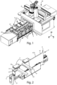
figure 1 shows an axonometric view of a machine tool comprising an auxiliary loading device improved according to the invention; -
figure 2 shows an axonometric view of a bar of the machinefigure 1 , equipped with an auxiliary loading device according to the invention, in which a lifting element is in a second raised position; -
figure 3 shows an axonometric view of a bar of the machine shown infigure 1 , equipped with an auxiliary loading device according to the invention, in which a lifting element is in a second raised position; -
figure 4 shows an axonometric view of a bar of the machine offigure 1 , equipped with an improved auxiliary loading device according to the invention, in which a lifting element is in a first lowered position; -
figure 5 shows a front view of a bar of a machine equipped with an auxiliary loading device according to the invention; -
figures 6A to 7 show front views of alternative embodiments of a lifting element provided in an auxiliary loading device according to the invention; and -
figures 8A to 11C show steps of a method of operation of a machine according to the invention. - In the various figures the similar parts will be indicated with the same numerical references.
- With reference to the attached figures, it is observed a machine M for machining pieces made of wood or similar materials, composite, polymeric, ceramic, metallic or other materials equipped with one or more loading
auxiliary devices 4 to load the pieces P to be machined. - In the following the description will be directed to a machine tool, also known as a machining center, but it is clear that it should not be considered limited to this specific use.
- Referring to
figure 1 , a machine M is observed, comprising a workingplane 1, of the so-called bar type, for supporting and blocking the pieces to be machined, having one ormore bars 2. - Each
bar 2 extends predominantly in a first Y direction. Thebars 2 are generally arranged on a base and are slidably movable on it. - The machine M also has a crossbar 6, which can be mobile or fixed with respect to the working
plane 1. The crossbar 6 supports one or more machining heads 7. - As can be seen from
figures 2-5 , the machine M also comprises one or moreauxiliary loading devices 4, respectively associated with at least onerespective bar 2, comprising at least one liftingelement 41 to support the piece P, in which thelifting element 41 is movable in a second direction Z, perpendicular to the working plane, between a first lowered position T, and a second raised position V with respect to the workingplane 1. - The lifting
element 41 can be moved in the second Z direction via a first actuator. - Each
bar 2 has alateral surface 21 and generally each liftingelement 41 is arranged on saidlateral surface 21 of arespective bar 2 and extends mainly in the first Y direction, parallel to thebar 2 on which it is arranged. - In the embodiment shown in the figures, the lifting
element 41 is slab-shaped. In other embodiments it may have different shapes. - In the embodiment shown in the figures, the working
plane 1 extends mainly in a third X direction, perpendicular to the first Y direction and to the second Z direction. - In an alternative embodiment, the working
plane 1 extends predominantly in one direction, parallel to the first Y direction, i.e. the direction of maximum extension of eachbar 2. - The machine M also includes one or
more blocking devices 3, arranged and slidingly mobile on said one ormore bars 2, to support and block the pieces P to be machined. - In the embodiment shown in the figures, the
blocking devices 3 are clamping members, each comprising alower jaw 31, having asupport surface 311 for resting said piece P, and anupper jaw 32, relatively movable towards and away from each other, in the second Z direction. - The
lower jaw 31 and/or theupper jaw 32 can be moved by a second actuator. - In another embodiment, the
blocking devices 3 are retention or blocking members for blocking the pieces P to be machined by vacuum. - The machine M also comprises at least one
abutment member 5, having anend 51, arranged on at least one of said one ormore bars 2, to position said piece P in abutment against saidabutment member 5. - The
abutment member 5 is mobile in the second Z direction between a retracted position and an extracted position, with respect to at least one of thebars 2. - The
abutment member 5 can also be mobile in the first Y direction. - The one or more
auxiliary loading devices 4 comprise at least oneabutment element 42, 42' arranged on the liftingelement 41, to move the piece P by relative motion towards theabutment element 42, 42', so as to be abutting against theabutment element 42, 42', when the liftingelement 41 is in the second raised position V. - In the embodiment shown in
figures 1-6D and8A-11C , theabutment element 42 is an integral part of the liftingelement 41. - The lifting
element 41 has anupper surface 410. Theupper surface 410 comprises at least a portion parallel to said workingplane 1 and at least a portion perpendicular to said working plane, the latter corresponding to theabutment element 42. -
Figures 6A-6D show alternative embodiments for the liftingelement 41, each comprising a plurality ofabutment elements 42. - In an alternative embodiment, shown in
figure 7 , the abutment element 42' is arranged on the liftingelement 41 and is movable in the first Y direction and/or in the second Z direction. By way of example, the abutment element 42' is represented as a cylindrical pin. - The operation of the machine M described above is as follows.
- As can be seen in
figure 8A , the liftingelement 41 is arranged in the second raised position V, the piece P is placed on the lifting element and is arranged against the liftingelement 42. - In the embodiment in which the abutment element 42' is mobile in the first Y direction and/or in the second Z direction, the piece P is moved with relative motion towards the abutment element 42' and is placed in abutment against it.
- In the embodiment in which the
blocking devices 3 are clamping members, as can be seen fromfigure 8B , the liftingelement 41 is moved along the second direction Z in a third intermediate position U, between the second raised position V and the first lowered position T. The third intermediate position U is such that the piece P is in a position, along the second direction Z, intermediate between a first height of thelower jaw 31 and a second height of theupper jaw 32. - As can be seen from
figure 8C , at least one of the one ormore clamping members 3 is moved with relative motion approaching the piece P, in the first direction Y, in a position such that the piece P is, at least partially, in a volume having thesupport surface 311 as its base area. - As can be seen from
figure 8D , the lifting element is moved, along the second direction Z, to the first lowered position T, in such a way that the piece P is no longer in contact with the liftingelement 41 and is supported only by thelower jaw 31. - In the embodiment in which the
abutment member 5 is present, as can be seen infigure 9A , the piece P is moved with relative motion, in the first Y direction, towards theabutment member 5, so as to bring it to rest with it, in order to increase the precision of the positioning of the piece P, obtained through the abutment position against theabutment element 42, 42'. - In case of the
abutment member 5 is interposed, along the first direction Y, between at least one of the one ormore clamping members 3 and the piece P, the third intermediate position U must be such that the piece P is in a position, in the second Z direction, intermediate between a height of anend 51 of saidabutment member 5, distal with respect to one ormore bars 2, and a second height of theupper jaw 32. - As can be seen in
figure 9B , thelower jaw 31 and/or theupper jaw 32 are moved with relative motion in approach, so as to clamp the piece P. - As shown in
figure 9C , the clampingmember 3 can be moved along therespective bar 2 together with the piece P. -
Figures 10A-11C illustrate the unloading step of the piece P. It is observed that the clampingmember 3 can be moved along therespective bar 2, approaching said abutment element (42; 42'). - The
lower jaw 31 and/or theupper jaw 32 are moved away by relative motion, so as to unlock the piece P. - The lifting
element 41 is moved, along said second direction Z, to the third intermediate position U, in such a way as to intercept and lift said piece (P). - The clamping
member 3 is moved along the first Y direction, away from the abutment element (42; 42'). The liftingelement 41 is moved along the second direction Z, in the second raised position V. - Finally the piece P can be unloaded from the machine M.
- An advantage of the present invention is that it facilitates the loading of a plurality of pieces into the machine at the same time.
- Another advantage of the present invention is to provide an improved loading auxiliary device that makes loading pieces ergonomic.
- A further advantage of the present invention is that of creating a machine tool equipped with improved auxiliary loading devices having competitive costs compared to the prior art, and which overcomes the technical problems of the prior art.
- The present invention has been described for illustrative but not limitative purposes, according to its preferred embodiments, but it is to be understood that modifications and/or changes can be introduced by those skilled in the art without departing from the relevant scope as defined in the enclosed claims.
(b1) moving said piece with relative motion towards said abutment element, so as to abut against said abutment element.
Claims (14)
- Machine (M) for machining a piece (P) made of wood or similar materials, in composite, polymeric, ceramic, or other materials, comprising:a working plane (1) having one or more bars (2), which mainly extend in a first direction (Y); andone or more loading auxiliary devices (4), each associated with at least one respective of said bars (2), wherein each auxiliary device (4) comprisesat least one lifting element (41), to support said piece (P),wherein said lifting element (41) is movable in a second direction (Z) perpendicular to said working plane (1), between a first lowered position (T) and a second raised position (V) with respect to said working plane (1);wherein said machine (M) is characterized in that each of said one or more loading auxiliary devices (4) comprises at least one abutment element (42; 42'), arranged on said lifting element (41), for positioning said piece (P) abutting against said abutment element (42; 42'), when said lifting element (41) is in said second raised position (V).
- Machine (M) according to claim 1, characterized in that it comprises one or more blocking devices (3) arranged and slidingly movable slide on said one or more bars (2).
- Machine (M) according to any one of the preceding claims, characterized in that said lifting element (41) extends mainly in said first direction (Y).
- Machine (M) according to any of the preceding claims, characterized in that said at least one abutment element (42') is movable in said first direction (Y) and/or in said second direction (Z).
- Machine (M) according to any one of claims 1-3 characterized in that said at least one abutment element (42) is integral with said lifting element (41).
- Machine (M) according to the preceding claim, characterized in that said at least one lifting element (41) has an upper surface (410), and in that said abutment element (42) is obtained by shaping said upper surface (410).
- Machine (M) according to any one of the preceding claims characterized in that it comprises at least one abutment member (5), having one end (51), arranged on at least one of said one or more bars (2), for positioning said piece (P) in abutment against said abutment member (5).
- Machine (M) according to the preceding claim, characterized in that said abutment member (5) is movable in said second direction (Z) between a retracted position and an extracted position, with respect to at least one of said one or more bars (2).
- Machine (M) according to any one of the preceding claims, characterized in that said one or more blocking devices (3) are clamping members, each comprising a lower jaw (31), having a support surface (311) for resting said piece (P), and an upper jaw (32), wherein said jaws (31, 32) are relatively movable towards and away, in said second direction (Z).
- Method of operation of a machine (M) according to any one of claims 1-9, comprising the following steps:(a) moving said lifting element (41), along said second direction (Z), in said second raised position (V); and(b) positioning said piece (P) on said at least one lift element (41);wherein said method is characterized in that said step (b) includes the following sub-step:
(b1) moving said piece (P) with relative motion towards said abutment element (42; 42'), so as to abut against said abutment element (42; 42'). - Method of operation of a machine (M) according to the preceding claim, when dependent on claim 9, characterized in that it comprises, after said step (b1), the following further following steps:(c) moving said at least one lifting element (41), along said second direction (Z), to a third intermediate position (U), between said second raised position (V) and said first lowered position (T), said third intermediate position (U) being such that said piece (P) is in an intermediate position between a first height of said lower jaw (31) and a second height of said upper jaw (32);(d) moving at least one of said one or more clamping elements (3) of relative motion towards said piece (P), in said first direction (Y), in a position such that said piece (P) is, at least partially, in a volume having as base area said support surface (311);(e) moving said at least one lifting element (41), along said second direction (Z), in said first lowered position (T), so that said piece (P) is no longer in contact with said lifting element (41 );(f) moving said lower jaw (31) and/or said upper jaw (32) in relative approach in said second direction (Z), so as to clamp said piece (P).
- Method of operation of a machine (M) according to the preceding claim, characterized in that it comprises the following further steps:(g) moving at least one of said one or more clamping elements (3), supporting said piece (P), along said first direction (Y), towards said abutment element (42; 42');(h) moving said lower jaw (31) and/or said upper jaw (32) in relative distancing in said second direction (Z), so as to unlock said piece (P);(i) moving said at least one lifting element (41), along said second direction (Z), in said third intermediate position (U), so as to intercept and lift said piece (P);(l) moving at least one of said one or more clamping elements (3), along said first direction (Y), away from said abutment element (42; 42');(m) moving said lifting element (41), along said second direction (Z), in said second raised position (V).
- Method of operation of a machine (M) according to any one of claims 11 or 12, wherein said machine (M) comprises at least one abutment member (5), arranged on at least one of said one or more bars (2), to position said piece (P) in abutment against said abutment member (5), said method further comprising after said step (e) and before said step (f), the following step:
(e1) moving said piece (P) in said first direction (Y) towards said abutment member (5) so as to bring it into abutment with said abutment member (5). - Method of operation of a machine (M) according to the preceding claim in which said abutment member (5) is interposed, in said first direction (Y), between said at least one of said one or more clamping members (3) and said piece (P), said method being characterized in that said step (c) further provides that said third intermediate position (U) is such that said piece (P) is in a position, in said second direction (Z), intermediate between a height of one end (51) of said abutment member (5), distal with respect to one of said one or more bars (2), and a second height of said upper jaw (32).
Applications Claiming Priority (1)
| Application Number | Priority Date | Filing Date | Title |
|---|---|---|---|
| IT102023000013440A IT202300013440A1 (en) | 2023-06-28 | 2023-06-28 | MACHINE TOOL WITH IMPROVED PIECE LOADING SYSTEM AND RELATED METHOD |
Publications (1)
| Publication Number | Publication Date |
|---|---|
| EP4491359A1 true EP4491359A1 (en) | 2025-01-15 |
Family
ID=88098059
Family Applications (1)
| Application Number | Title | Priority Date | Filing Date |
|---|---|---|---|
| EP24182730.2A Pending EP4491359A1 (en) | 2023-06-28 | 2024-06-18 | Machine tool with improved workpiece loading system and method thereof |
Country Status (2)
| Country | Link |
|---|---|
| EP (1) | EP4491359A1 (en) |
| IT (1) | IT202300013440A1 (en) |
Citations (4)
| Publication number | Priority date | Publication date | Assignee | Title |
|---|---|---|---|---|
| ITFI20100071A1 (en) * | 2010-04-16 | 2011-10-17 | Paolino Bacci Srl | "MACHINE TOOL WITH POWER SYSTEM FOR WORKING PARTS" |
| IT201700083048A1 (en) * | 2017-07-20 | 2019-01-20 | Pade S A S Di De Moliner Vinicio & C Ora Pade S R L | Piece loading assembly of a work center |
| EP3552786A1 (en) * | 2018-04-13 | 2019-10-16 | SCM Industria S.P.A. | Machine and method for machining an edge of a workpiece |
| EP3639971A1 (en) * | 2018-10-15 | 2020-04-22 | Michael Weinig AG | Method for machining elongated workpieces made of wood, plastic and the like, and machine for carrying out said method |
-
2023
- 2023-06-28 IT IT102023000013440A patent/IT202300013440A1/en unknown
-
2024
- 2024-06-18 EP EP24182730.2A patent/EP4491359A1/en active Pending
Patent Citations (4)
| Publication number | Priority date | Publication date | Assignee | Title |
|---|---|---|---|---|
| ITFI20100071A1 (en) * | 2010-04-16 | 2011-10-17 | Paolino Bacci Srl | "MACHINE TOOL WITH POWER SYSTEM FOR WORKING PARTS" |
| IT201700083048A1 (en) * | 2017-07-20 | 2019-01-20 | Pade S A S Di De Moliner Vinicio & C Ora Pade S R L | Piece loading assembly of a work center |
| EP3552786A1 (en) * | 2018-04-13 | 2019-10-16 | SCM Industria S.P.A. | Machine and method for machining an edge of a workpiece |
| EP3639971A1 (en) * | 2018-10-15 | 2020-04-22 | Michael Weinig AG | Method for machining elongated workpieces made of wood, plastic and the like, and machine for carrying out said method |
Also Published As
| Publication number | Publication date |
|---|---|
| IT202300013440A1 (en) | 2024-12-28 |
Similar Documents
| Publication | Publication Date | Title |
|---|---|---|
| US5700117A (en) | Machine tool for machining panels and plates | |
| EP1712337B1 (en) | Machining centre with two operating units with part handling means | |
| JP2022545866A (en) | Material automatic supply/discharge processing system | |
| US5829151A (en) | Multi-axis part positioning system | |
| US5897275A (en) | Machine tool for machining panels and plates | |
| US7272882B1 (en) | Multiple table routing machine with roller hold-down | |
| EP2030745B1 (en) | Structure for feeding automatic panel cutting machines | |
| JPH0716722B2 (en) | Punching machine with replaceable punching tool and work feeding device | |
| CN114786869B (en) | Machining unit with at least two machining robots | |
| EP2991811B1 (en) | Machining center | |
| CN114786867A (en) | Machining unit with tool carrier | |
| EP4070913A1 (en) | A machine tool with retractable members for clamping the workpieces to be machined | |
| CN110238679B (en) | a pneumatic clamp | |
| EP1247611B1 (en) | A multi-axis work centre, for multiple production, in particular for wood working | |
| JPH0829472B2 (en) | Centering and gripping system | |
| ITTO971119A1 (en) | PANEL DRILLING MACHINE WITH CHANGE HEADS DRILLING UNIT AND RELATED OPERATING METHOD. | |
| US20090090155A1 (en) | Sheet-Metal Working Machine and Method for Machining Sheets | |
| US20200139516A1 (en) | Clamping device with excavation function | |
| KR102454459B1 (en) | High rigidity bed device with anti-sag function of vertical machining center | |
| CN216370998U (en) | Special horizontal machining center of front axle | |
| KR100633571B1 (en) | Machining Center of Machining Center | |
| JP2003117749A (en) | Work positioning device for machine tools | |
| CN220554995U (en) | Positioning device | |
| WO2001089759A1 (en) | Centre for machining workpieces | |
| CN116475492B (en) | Oblique fracture saw installation workbench |
Legal Events
| Date | Code | Title | Description |
|---|---|---|---|
| PUAI | Public reference made under article 153(3) epc to a published international application that has entered the european phase |
Free format text: ORIGINAL CODE: 0009012 |
|
| STAA | Information on the status of an ep patent application or granted ep patent |
Free format text: STATUS: THE APPLICATION HAS BEEN PUBLISHED |
|
| AK | Designated contracting states |
Kind code of ref document: A1 Designated state(s): AL AT BE BG CH CY CZ DE DK EE ES FI FR GB GR HR HU IE IS IT LI LT LU LV MC ME MK MT NL NO PL PT RO RS SE SI SK SM TR |
|
| STAA | Information on the status of an ep patent application or granted ep patent |
Free format text: STATUS: REQUEST FOR EXAMINATION WAS MADE |
|
| 17P | Request for examination filed |
Effective date: 20250618 |
|
| STAA | Information on the status of an ep patent application or granted ep patent |
Free format text: STATUS: EXAMINATION IS IN PROGRESS |
|
| 17Q | First examination report despatched |
Effective date: 20250724 |
|
| GRAP | Despatch of communication of intention to grant a patent |
Free format text: ORIGINAL CODE: EPIDOSNIGR1 |
|
| STAA | Information on the status of an ep patent application or granted ep patent |
Free format text: STATUS: GRANT OF PATENT IS INTENDED |
|
| INTG | Intention to grant announced |
Effective date: 20260313 |