EP4491262A1 - Turbulent flow promoting surface and method, and use of said surface in fluid aeration - Google Patents
Turbulent flow promoting surface and method, and use of said surface in fluid aeration Download PDFInfo
- Publication number
- EP4491262A1 EP4491262A1 EP22768931.2A EP22768931A EP4491262A1 EP 4491262 A1 EP4491262 A1 EP 4491262A1 EP 22768931 A EP22768931 A EP 22768931A EP 4491262 A1 EP4491262 A1 EP 4491262A1
- Authority
- EP
- European Patent Office
- Prior art keywords
- promoters
- cavity
- fluid
- surface according
- previous
- Prior art date
- Legal status (The legal status is an assumption and is not a legal conclusion. Google has not performed a legal analysis and makes no representation as to the accuracy of the status listed.)
- Granted
Links
Images



Classifications
-
- B—PERFORMING OPERATIONS; TRANSPORTING
- B01—PHYSICAL OR CHEMICAL PROCESSES OR APPARATUS IN GENERAL
- B01F—MIXING, e.g. DISSOLVING, EMULSIFYING OR DISPERSING
- B01F23/00—Mixing according to the phases to be mixed, e.g. dispersing or emulsifying
- B01F23/20—Mixing gases with liquids
- B01F23/23—Mixing gases with liquids by introducing gases into liquid media, e.g. for producing aerated liquids
- B01F23/234—Surface aerating
- B01F23/2341—Surface aerating by cascading, spraying or projecting a liquid into a gaseous atmosphere
-
- C—CHEMISTRY; METALLURGY
- C02—TREATMENT OF WATER, WASTE WATER, SEWAGE, OR SLUDGE
- C02F—TREATMENT OF WATER, WASTE WATER, SEWAGE, OR SLUDGE
- C02F3/00—Biological treatment of water, waste water, or sewage
-
- B—PERFORMING OPERATIONS; TRANSPORTING
- B01—PHYSICAL OR CHEMICAL PROCESSES OR APPARATUS IN GENERAL
- B01F—MIXING, e.g. DISSOLVING, EMULSIFYING OR DISPERSING
- B01F23/00—Mixing according to the phases to be mixed, e.g. dispersing or emulsifying
- B01F23/20—Mixing gases with liquids
- B01F23/23—Mixing gases with liquids by introducing gases into liquid media, e.g. for producing aerated liquids
- B01F23/231—Mixing gases with liquids by introducing gases into liquid media, e.g. for producing aerated liquids by bubbling
- B01F23/23105—Arrangement or manipulation of the gas bubbling devices
- B01F23/2312—Diffusers
- B01F23/23126—Diffusers characterised by the shape of the diffuser element
- B01F23/231263—Diffusers characterised by the shape of the diffuser element having dome-, cap- or inversed cone-shape
-
- B—PERFORMING OPERATIONS; TRANSPORTING
- B01—PHYSICAL OR CHEMICAL PROCESSES OR APPARATUS IN GENERAL
- B01F—MIXING, e.g. DISSOLVING, EMULSIFYING OR DISPERSING
- B01F23/00—Mixing according to the phases to be mixed, e.g. dispersing or emulsifying
- B01F23/20—Mixing gases with liquids
- B01F23/23—Mixing gases with liquids by introducing gases into liquid media, e.g. for producing aerated liquids
-
- B—PERFORMING OPERATIONS; TRANSPORTING
- B01—PHYSICAL OR CHEMICAL PROCESSES OR APPARATUS IN GENERAL
- B01F—MIXING, e.g. DISSOLVING, EMULSIFYING OR DISPERSING
- B01F23/00—Mixing according to the phases to be mixed, e.g. dispersing or emulsifying
- B01F23/20—Mixing gases with liquids
- B01F23/23—Mixing gases with liquids by introducing gases into liquid media, e.g. for producing aerated liquids
- B01F23/231—Mixing gases with liquids by introducing gases into liquid media, e.g. for producing aerated liquids by bubbling
-
- B—PERFORMING OPERATIONS; TRANSPORTING
- B01—PHYSICAL OR CHEMICAL PROCESSES OR APPARATUS IN GENERAL
- B01F—MIXING, e.g. DISSOLVING, EMULSIFYING OR DISPERSING
- B01F23/00—Mixing according to the phases to be mixed, e.g. dispersing or emulsifying
- B01F23/20—Mixing gases with liquids
- B01F23/23—Mixing gases with liquids by introducing gases into liquid media, e.g. for producing aerated liquids
- B01F23/231—Mixing gases with liquids by introducing gases into liquid media, e.g. for producing aerated liquids by bubbling
- B01F23/23105—Arrangement or manipulation of the gas bubbling devices
- B01F23/2312—Diffusers
-
- B—PERFORMING OPERATIONS; TRANSPORTING
- B01—PHYSICAL OR CHEMICAL PROCESSES OR APPARATUS IN GENERAL
- B01F—MIXING, e.g. DISSOLVING, EMULSIFYING OR DISPERSING
- B01F23/00—Mixing according to the phases to be mixed, e.g. dispersing or emulsifying
- B01F23/20—Mixing gases with liquids
- B01F23/23—Mixing gases with liquids by introducing gases into liquid media, e.g. for producing aerated liquids
- B01F23/231—Mixing gases with liquids by introducing gases into liquid media, e.g. for producing aerated liquids by bubbling
- B01F23/23105—Arrangement or manipulation of the gas bubbling devices
- B01F23/2312—Diffusers
- B01F23/23126—Diffusers characterised by the shape of the diffuser element
-
- B—PERFORMING OPERATIONS; TRANSPORTING
- B01—PHYSICAL OR CHEMICAL PROCESSES OR APPARATUS IN GENERAL
- B01F—MIXING, e.g. DISSOLVING, EMULSIFYING OR DISPERSING
- B01F23/00—Mixing according to the phases to be mixed, e.g. dispersing or emulsifying
- B01F23/20—Mixing gases with liquids
- B01F23/23—Mixing gases with liquids by introducing gases into liquid media, e.g. for producing aerated liquids
- B01F23/2319—Methods of introducing gases into liquid media
-
- C—CHEMISTRY; METALLURGY
- C02—TREATMENT OF WATER, WASTE WATER, SEWAGE, OR SLUDGE
- C02F—TREATMENT OF WATER, WASTE WATER, SEWAGE, OR SLUDGE
- C02F3/00—Biological treatment of water, waste water, or sewage
- C02F3/02—Aerobic processes
- C02F3/12—Activated sludge processes
-
- C—CHEMISTRY; METALLURGY
- C02—TREATMENT OF WATER, WASTE WATER, SEWAGE, OR SLUDGE
- C02F—TREATMENT OF WATER, WASTE WATER, SEWAGE, OR SLUDGE
- C02F3/00—Biological treatment of water, waste water, or sewage
- C02F3/02—Aerobic processes
- C02F3/12—Activated sludge processes
- C02F3/20—Activated sludge processes using diffusers
Definitions
- the present invention relates to a surface for use in the aeration of fluids, namely to a surface comprised of bag like structures that promote the turbulent flow of fluids.
- Aquatic locations that present low DO levels inherently present high oxygen demand which can be chemical (chemical oxygen demand, COD) or biochemical (biochemical oxygen demand, BOD).
- COD chemical oxygen demand
- BOD biochemical oxygen demand
- concentrations of oxidative organic molecules and/or large amounts of aerobic organisms are present in a large excess in water, relative to the existing concentration of dissolved oxygen (Oxygen saturation, SO 2 ).
- wastewater treatment plants were developed and installed worldwide, wherein residual waters are treated in such a way that can then be safely released to rivers or seas, with pollution levels considered environmentally acceptable. These plants present at least one water aeration system, which allows for improved oxidation of organic compounds and promotes the growth of aerobic organisms, therefore raising the degradation of biological matter present in wastewaters. As such, less nutrients are released to aquatic habitats, reducing the effect of eutrophication.
- Document US2016214071 presents one technology initially developed by Anzai Kantetsu KK, but applied in wine aeration.
- the system comprises a pump, a hose attached to the pump by a first nozzle, a gas conduit coupled to a second nozzle of the hose and submerged in wine, having at the tip a porous ceramic composite. Air propelled by the pump passes with a large pressure through the pores of the ceramic composite, releasing a large amount of fine bubbles. Fine bubbles are characterized by having a diameter between 10 ⁇ m and 2 mm, also called microbubbles.
- Nanobubbles or ultrafine bubbles, have a diameter in the nanometre scale. Microbubbles are known in the field for exponentially decreasing in size within 5 minutes, becoming nanobubbles. Due to the high amount of bubbles present in the water, the air-water interface increases considerably, increasing, thus the percentage of SO 2 in the water.
- the SIO solution from the company Ultrafine Nanobubble Cavitation uses a static mixer that forms nanobubbles by promoting turbulent flow. Water, passing through the interior of this mixer, hits propeller-shaped blades that are located at the inlet of the mixer. By hitting these blades, the water dissipates, forming bubbles. Water, now with bubbles and in turbulent flow, passes through existing blades inside the mixer that divide the water stream into two directions, forming more bubbles, also splitting the bubbles already formed. This way, bubbles become microbubbles, moving on to nanobubbles. At the exit, water stream returns to a laminar flow, but with a large amount of nanobubbles.
- Turbulent flow is also known for raising SO 2 values. Turbulent flow happens when a circulating fluid finds an obstacle. When that happens, fluid changes direction, losing momentum and therefore entering turbulent flow. Since the movement of a fluid in turbulent flow is random, the air-water interface grows. Turbulent flow and an increase in the air-water interface together raise the tendency for air bubbles to be generated, making the air-water interface larger.
- the equipment of present invention has the objective of promoting turbulent flow, through a technique similar to the one stated in document CN105036296 .
- the equipment of the present invention comprises a protruding surface comprising protuberances where a fluid to be aerated passes through.
- protuberances further comprise a trench that promotes mixing between air and fluid, and a lateral blockage that obstructs the flow of the fluid in turbulent flow to the outside of the trench, by blocking the lateral openings of the trench.
- This synergistic effect allows for greater mixing between fluid and air, by promoting the formation of turbulent flow through the three individual components of the equipment of the present invention, significantly improving the formation of microbubbles and nanobubbles, and, thus, aeration of the fluid.
- the equipment of the present invention can also be applied in any state of the art solutions presented above, thereby exponentially improving the performance of such solutions.
- the equipment of the present invention can also be applied in other solutions that have the objective of fluid aeration and/or turbulent flow generation.
- translational repetition is meant the successive and indefinite repetition of components of the equipment of the present invention over a two-dimensional plane, wherein a copy of one component of the equipment of the present invention is set over a substantially linear position in relation to the original component, without any rotation or change of any feature or position of the copied component.
- laterally positioned is meant the placement of one element of equipment of the present invention to the right or to the left of another element, such that both elements are in physical contact with each other.
- geometrical pattern is meant the two-dimensional plane formed by the ordered placement of elements of the equipment of the present invention.
- fluid stream is meant the initial fluid flow that streams along the surface of the equipment of the present invention.
- Turbulent flow promoting surfaces in accordance with the principles described herein can comprise any number of the features described. Similarly, the principles described herein can be applied to any turbulent flow promoting surface.
- the equipment of the present invention can be applied to any surface, flat or curved, of any equipment used for aeration or promotion of turbulent flow, namely but not exclusively, in composting fermenters, wastewater treatment plants, drink and soda aerators, marine animal raising systems, aerator shovels, fluid transport equipment, and marine vessels.
- the equipment of the present invention comprises a surface (1) which is applied over a base.
- the base can be manufactured in any material adequate for use in fluids, namely water, such as, namely, but not exclusively, heavy metals, steel, aluminium, plastic polymers and copolymers, organic polymers and copolymers, glass, carbon fibre, varnished cellulose, cellulose coated with plastic polymers or copolymers, and varnished wood.
- the surface (1) is applied over the base.
- the surface (1) comprises an undefined translational repetition of turbulent flow promoters (2).
- the surface (1) is the base itself.
- Each promoter (2) comprises a protuberance (2.1).
- the protuberance (2.1) presents any shape adequate for the effect, namely but not exclusively, substantially hemispherical, substantially pyramidal, substantially parallelepiped, substantially prismatic, substantially conical, substantially frustum shaped, substantially frustoconical, or substantially halfpipe, preferably substantially hemispherical.
- the protuberance (2.1) is set on the surface (1) and comprises an inferior cut in a substantially halfpipe shape at the end of the protuberance (2.1) that is in contact with the surface (1). In a position superior to the cut stated above, the protuberance (2.1) presents a second superior cut, substantially circular, the extremity of which contours the wall of the protuberance (2.1) and forms an edge (2.1.2).
- the protuberance (2.1) serves as an obstacle to the path of the fluid stream (3), thereby promoting turbulent flow. Fluid hits the protuberance (2.1), thereby losing directional stability, entering turbulent flow, and engulfing the protuberance (2.1) to continue moving in its original direction.
- the protuberance (2.1) comprises a trench (2.2), that, in a preferred embodiment, presents a substantially halfpipe shape that is substantially complementary to the shape of the inferior cut of the protuberance (2.1). I.e., the inferior cut done to the protuberance (2.1) with the trench (2.2) forms a cavity (2.1.1) with a substantially cylindrical shape, hollow in its interior.
- the protuberance (2.1) also presents a central opening (2.1.3) obtained from the circular cut done to the protuberance (2.1), above the inferior cut.
- the cavity (2.1.1) is located at the contact zone between the protuberance (2.1) and the surface (1), preferably in a substantially perpendicular position in relation to the direction of the fluid stream (3) and in such a way that the stream directly enters the cavity (2.1.1).
- the trench (2.2) presents a shape selected from, namely, but not exclusively, substantially parallelepiped, substantially prismatic, substantially conical, substantially frustum shaped, or substantially frustoconical.
- the edge (2.1.2) cuts the fluid stream (3) into two streams.
- One of these streams engulfs the protuberance (2.1) by the upper and lateral sides, continuing in its original direction, while the other stream goes into the cavity (2.1.1) through the central opening (2.1.3).
- the cavity (2.1.1) receives the circulating fluid, obstructing its flow.
- the curved, half closed shape of the protuberance (2.1) forces the fluid into entering the cavity (2.1.1) through the central opening (2.1.3).
- the cylindrical format of the cavity (2.1.1) allows fluid to circulate repeatedly on its interior in a substantially circular stream cycle, hampering its exit from the cavity (2.1.1), thereby allowing further promotion of turbulent flow and higher bubble generation. Due to the clash with the protuberance (2.1), the fluid is already partly in turbulent flow. The circulation of the fluid in the cavity (2.1.1) therefore considerably raises the generation of microbubbles and nanobubbles.
- the cavity (2.1.1) presents two lateral openings, each positioned at both lateral ends of the cavity (2.1.1), opposite of each other. At one or both of these lateral openings, in a preferred embodiment, is a blockage element (2.3) which impedes fluid from escaping the cavity (2.1.1) from the lateral opening where it is positioned. Given that, in a preferred embodiment, one promoter (2) is laterally positioned alongside adjacent promoters (2), the other lateral opening is blocked by the blockage element (2.3) of the adjacent promoter (2). When, in an embodiment, a promoter (2) is not laterally positioned alongside an adjacent promoter (2), both lateral openings are blocked by a blockage element (2.3) .
- the blockage element (2.3) has a shape that is substantially complementary with the shape of the cavity (2.1.1) . This way, the fluid can only enter the cavity (2.1.1) through the central opening (2.1.3) and leave through the same central opening (2.1.3). The exit pressure will therefore be maximal in the side of the blockage element (2.3) directed towards the cavity (2.1.1), where flow perturbation and bubble generation will be higher.
- the blockage element (2.3) has dimensions smaller than the dimensions of the lateral openings of the cavity (2.1.1), allowing for a small amount of fluid to escape from the lateral openings.
- the distance between two adjacent promoters (2) is substantially the same as the distance between any other two adjacent promoters (2). In another embodiment, the distance between two adjacent promoters (2) is dependent on the distance between any other two adjacent promoters (2), such that both present a higher or lower distance relative to a distance between any other two adjacent promoters (2). In yet another embodiment, the distance between two adjacent promoters (2) is independent from the distance between any other two promoters (2), having substantially equal or different distances, without any specific correlation.
- both dependency wherein the distance between two adjacent promoters (2) is substantially equal or metrically dependent on the distance between any other two adjacent promoters (2)
- independency wherein the distance between two adjacent promoters (2) is independent from the distance between any other two adjacent promoters (2)
- the distance between two adjacent promoters (2) is such that the blockage element (2.3) of a first promotor (2) is placed on a lateral opening of the cavity (2.1.1) of a second promoter (2).
- Such allows the cavities (2.1.1) of the promoters (2) to be blocked on both lateral openings, obstructing the fluid stream (3) by the two lateral openings of the cavities (2.1.1).
- the dimensions of one promoter (2) are substantially equal to the dimensions of any other promoter (2). In another embodiment, the dimensions of one promoter (2) are dependent on the dimensions of any other promoter (2). In yet another embodiment, the dimensions of one promoter (2) are independent from the dimensions of any other promoter (2), being either substantially equal or different. In another embodiment, both dependency, wherein the dimensions of one promoter (2) are substantially equal or metrically dependent on the dimensions of any other promoter (2), and independency, wherein the dimensions of one promoter (2) are independent from the dimensions of any other promoter (2), exist.
- the promoters (2) are placed in a translational repetitive manner on the surface (1). Such translational repetition is achieved over the surface (1) plane, both horizontally and vertically, as observable in figure 1 .
- This translational repetition forms on the surface (1) a two-dimensional geometrical pattern of promoters (2).
- This geometrical pattern will from now on be defined as being a pattern that has an indefinite number of rows of promoters (2) that are substantially horizontal and substantially parallel between each other, in relation to the plane of the surface (1).
- the horizontal rows are aligned in such a way that each promoter (2) is aligned substantially vertically with the promoters (2) that are placed in the adjacent rows that are immediately above or immediately below, as can be observed in figure 1 .
- the horizontal rows are aligned in such way that each promoter (2) is not aligned substantially vertically with the promoters (2) that are placed in the adjacent rows that are above and below.
- each promoter (2) forms an angle with the promoters (2) that are placed in the rows immediately above and immediately below, as can be observed in figure 6 .
- Such an angle can be any angle adequate for the effect, such as angles between 80° and 10°, preferably between 60° and 30°, more preferably between 50° and 40°, namely 45°.
- the alignment of promoters (2) allows the setting of a geometrical pattern, namely quadrangular or diamond shaped.
- the alignment between promoters (2) may or may not form a geometrical pattern. Forming a geometrical pattern, it can have a regular repetition of horizontal rows.
- the order in the position of the promoters (2) depends on the use of the surface (1) of the equipment of the present invention, namely on the desired aeration level that the application should achieve.
- the ordered disposition of promoters (2) allows higher fluid dissipation that is directly proportional to higher aeration.
- an unordered disposition of promoters (2) including irregular distances between any two adjacent promoters (2), will dissipate the fluid with less intensity, aerating the fluid with lower intensity.
- the alignment between promoters (2) also depends on fluid viscosity.
- a fluid with higher viscosity has a smaller tendency to enter turbulent flow, requiring a higher degree of dissipation.
- a fluid with lower viscosity has a higher tendency to enter turbulent flow, so a surface (1) that presents less promoters (2) can be used, thereby saving resources on the production of the equipment of the present invention.
- solids, such as debris, present on a fluid will increase the viscosity of the fluid, which will also affect the embodiment of the present invention being used.
- the dimensions of promoters (2) also affect the promoted turbulence, namely due to the presence of debris. If a fluid presents higher amounts of debris, the dimensions of the promoters (2) should preferably be smaller, to avoid excessive clashing between debris and promoters (2), therefore allowing the existence of a wider area in which fluid can enter turbulent flow. In the case of fluid with fewer debris, the dimensions of the promoters (2) can be larger, therefore optimizing the area available for fluid dissipation.
- the promotion of turbulent flow is initiated when the fluid stream (3) starts moving along the surface (1).
- the fluid stream (3) hits the exterior side of the protuberances (2.1), namely against the edge (2.1.2), splitting it into two streams, such that one of these streams goes down and enters the cavity (2.1.1) by the central opening (2.1.3), while the other streams engulfs the protuberance (2.1) by the upper and lateral sides, being directed to the promoters (2) that comprise the following rows of promoters (2).
- the stream that is sent to the cavity (2.1.1) is forced against the centre bottom of the cavity (2.1.1), which leads to a first fluid dispersion and pulverization.
- the already dispersed and pulverized fluid is further divided into two streams, each one being directly forced into each of the lateral openings of the cavity (2.1.1), thereby hitting the blockage elements (2.3), provoking a second dispersion and pulverization and forming an array of bubbles spreading in all directions.
- Part of the already dissipated and pulverized fluid is projected over the direction of the blockage element (2.3) standing in the opposite lateral opening, such that both projected streams clash against each other, substantially at the centre of the cavity (2.1.1), provoking a third fluid dispersion and pulverization.
- Each consecutive dispersion and pulverization generates more bubbles and of smaller dimensions than those formed by the previous dispersion and pulverization of fluid.
- fluid is bubbled.
- new fluid pushes the bubbled fluid out of the cavity (2.1.1).
- the process is therefore repeated indefinitely, as long as there is fluid in circulation.
- the bubbled fluid after getting out of the cavity (2.1.1), returns to the fluid stream (3) and enters the cavity (2.1.1) of another promoter (2), further intensifying the formation of bubbles.
- the repetition of the process intensifies formation of turbulent flow and the formation of microbubbles and nanobubbles, aerating the fluid with higher efficiency than the known solutions of the prior art.
- Another part of the fluid hits the lateral walls of the protuberances (2.1), causing additional pulverization.
- this pulverization occurs in the space between two adjacent promoters (2), which causes the pulverized fluid to clash with itself in the zone between the two promoters (2), further intensifying the formation of turbulent flow and of bubbles.
Landscapes
- Chemical & Material Sciences (AREA)
- Chemical Kinetics & Catalysis (AREA)
- Life Sciences & Earth Sciences (AREA)
- Biodiversity & Conservation Biology (AREA)
- Microbiology (AREA)
- Hydrology & Water Resources (AREA)
- Engineering & Computer Science (AREA)
- Environmental & Geological Engineering (AREA)
- Water Supply & Treatment (AREA)
- Organic Chemistry (AREA)
- Aeration Devices For Treatment Of Activated Polluted Sludge (AREA)
- Nozzles (AREA)
Abstract
Description
- The present invention relates to a surface for use in the aeration of fluids, namely to a surface comprised of bag like structures that promote the turbulent flow of fluids.
- Several industries use processes and systems that require that a fluid present specific parameters, wherein one of the components of said process or system is a fluid aerator, namely of water. Such industries need water to present a safe level of dissolved oxygen (DO) adequate for the growth of aerobic microorganisms. These microorganisms degrade biological matter that can be present in water, being the described aerators preferably used, namely, but not exclusively, in the treatment of wastewaters, in composting of organic products, and in aerating ponds, pools and water reservoirs.
- Aquatic locations that present low DO levels inherently present high oxygen demand, which can be chemical (chemical oxygen demand, COD) or biochemical (biochemical oxygen demand, BOD). In these conditions, concentrations of oxidative organic molecules and/or large amounts of aerobic organisms are present in a large excess in water, relative to the existing concentration of dissolved oxygen (Oxygen saturation, SO2). These conditions allow for the proliferation of anaerobic microorganisms, which further degrade the water quality.
- High levels of COD or BOD worsen the quality of life of aerobic species in water. For example, due to the high level of organic molecules that are present in sewage waters, the respective flow of these waters to rivers promotes eutrophication, wherein nutrient excess exponentially raises the amount of microorganisms in water. Such effect exponentially reduces water SO2 levels, making impossible the growth of aerobic microorganisms. Such makes the prospect of the water being naturally cleansed highly unlikely.
- To prevent eutrophication, wastewater treatment plants were developed and installed worldwide, wherein residual waters are treated in such a way that can then be safely released to rivers or seas, with pollution levels considered environmentally acceptable. These plants present at least one water aeration system, which allows for improved oxidation of organic compounds and promotes the growth of aerobic organisms, therefore raising the degradation of biological matter present in wastewaters. As such, less nutrients are released to aquatic habitats, reducing the effect of eutrophication.
- Even in aquatic habitats where a large amount of sludge has been released, being therefore devoid of aerobic organisms due to eutrophication, aeration allows new development of aquatic life in these habitats.
- In the composting of organic products, aerobic microorganisms consume nutrients, releasing other nutrients adequate for the growth of other microorganisms, and so on, creating a community that presents nutrient richness, making compost suitable for use by higher complexity organisms such as plants. Composting, by such reason, is mainly done for fertilizer production.
- The state of the art presents several solutions for water aeration.
- Document
US2016214071 presents one technology initially developed by Anzai Kantetsu KK, but applied in wine aeration. The system comprises a pump, a hose attached to the pump by a first nozzle, a gas conduit coupled to a second nozzle of the hose and submerged in wine, having at the tip a porous ceramic composite. Air propelled by the pump passes with a large pressure through the pores of the ceramic composite, releasing a large amount of fine bubbles. Fine bubbles are characterized by having a diameter between 10 µm and 2 mm, also called microbubbles. - Nanobubbles, or ultrafine bubbles, have a diameter in the nanometre scale. Microbubbles are known in the field for exponentially decreasing in size within 5 minutes, becoming nanobubbles. Due to the high amount of bubbles present in the water, the air-water interface increases considerably, increasing, thus the percentage of SO2 in the water.
- The equipment described in document
US3970731 produces the same effect than the one referred in the previous document, being however achieved by a porous plate placed at the end of a means for ejecting water, such as a faucet. - The SIO solution from the company Ultrafine Nanobubble Cavitation uses a static mixer that forms nanobubbles by promoting turbulent flow. Water, passing through the interior of this mixer, hits propeller-shaped blades that are located at the inlet of the mixer. By hitting these blades, the water dissipates, forming bubbles. Water, now with bubbles and in turbulent flow, passes through existing blades inside the mixer that divide the water stream into two directions, forming more bubbles, also splitting the bubbles already formed. This way, bubbles become microbubbles, moving on to nanobubbles. At the exit, water stream returns to a laminar flow, but with a large amount of nanobubbles.
- Turbulent flow is also known for raising SO2 values. Turbulent flow happens when a circulating fluid finds an obstacle. When that happens, fluid changes direction, losing momentum and therefore entering turbulent flow. Since the movement of a fluid in turbulent flow is random, the air-water interface grows. Turbulent flow and an increase in the air-water interface together raise the tendency for air bubbles to be generated, making the air-water interface larger.
- The equipment described in document
CN105036296 achieves this technical effect through a membrane that promotes turbulent flow comprised of spikes that separate water flowing through the membrane, promoting turbulent flow. - The equipment of present invention has the objective of promoting turbulent flow, through a technique similar to the one stated in document
CN105036296 . The equipment of the present invention comprises a protruding surface comprising protuberances where a fluid to be aerated passes through. Such protuberances further comprise a trench that promotes mixing between air and fluid, and a lateral blockage that obstructs the flow of the fluid in turbulent flow to the outside of the trench, by blocking the lateral openings of the trench. - This synergistic effect allows for greater mixing between fluid and air, by promoting the formation of turbulent flow through the three individual components of the equipment of the present invention, significantly improving the formation of microbubbles and nanobubbles, and, thus, aeration of the fluid.
- The equipment of the present invention can also be applied in any state of the art solutions presented above, thereby exponentially improving the performance of such solutions. The equipment of the present invention can also be applied in other solutions that have the objective of fluid aeration and/or turbulent flow generation.
- These and other features are to be easily understood by the accompanying drawings, which should be taken as examples only and are not to be considered as limiting the scope of the present invention. For illustrative purposes, the measurements of the elements in the drawings may be exaggerated and not drawn to scale. The absolute and relative dimensions do not match actual relations for carrying out the invention.
- In a preferred embodiment of the invention:
-
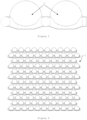
Figure 1 presents a view of an embodiment of the surface of the equipment of the present invention, wherein promoters are placed in a translational repetition, forming a geometrical pattern, with all components substantially aligned with a substantially perpendicular axis. -
Figure 2 presents a frontal superior perspective view of a promoter. -
Figure 3 presents a rear superior perspective view of a promoter. -
Figure 4 presents a top view of a promoter. -
Figure 5 presents a top view of two laterally positioned promoters, revealing the detail of the obstruction present in the trench. -
Figure 6 presents a view of an embodiment of the surface of the equipment of the present invention, such that the translational repetition of the promoters forms a geometrical pattern, with all components substantially aligned with a substantially diagonal axis. -
Figure 7 presents a view of the surface of the equipment of the present invention placed on a curved surface. -
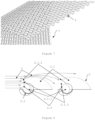
Figure 8 presents fluid stream directed along the surface of the equipment of the present invention. -
Figure 9 presents the path that the fluid stream follows upon finding a promoter of the surface of the equipment of the present invention. - In the drawings are marked the elements and components of the equipment of the present invention, as well as the elements and components necessary for the proper functioning of the invention:
- 1. surface
- 2. promotor
- 2.1. protuberance
- 2.1.1. cavity
- 2.1.2. edge
- 2.1.3. central opening
- 2.2. trench
- 2.3. blockage element
- 2.1. protuberance
- 3. fluid stream
- The shapes "substantially hemispherical", "substantially pyramidal", "substantially parallelepiped", "substantially prismatic", "substantially conic", "substantially frustum shaped", "substantially frustoconical", "substantially halfpipe", and "substantially complementary" are understood to be preferential shapes for embodiments of elements of the invention, which may also work with other shapes.
- The positions "substantially horizontal", "substantially vertical", "substantially aligned", "substantially perpendicular", and "substantially diagonal" are understood as possible positions for embodiments of elements of the invention, which may also work with other positions.
- By "translational repetition" is meant the successive and indefinite repetition of components of the equipment of the present invention over a two-dimensional plane, wherein a copy of one component of the equipment of the present invention is set over a substantially linear position in relation to the original component, without any rotation or change of any feature or position of the copied component.
- By "laterally positioned", as observable in
figure 5 , is meant the placement of one element of equipment of the present invention to the right or to the left of another element, such that both elements are in physical contact with each other. - By "geometrical pattern" is meant the two-dimensional plane formed by the ordered placement of elements of the equipment of the present invention.
- By "fluid stream" is meant the initial fluid flow that streams along the surface of the equipment of the present invention.
- As can be clear to a person skilled in the art, the application of the principles described herein is not limited to the embodiments shown. Possible changes that can occur in the present invention, defined in number, remain within the scope of the present invention.
- Turbulent flow promoting surfaces in accordance with the principles described herein can comprise any number of the features described. Similarly, the principles described herein can be applied to any turbulent flow promoting surface.
- Similarly, it is clear to a person skilled in the art that due to the nature of the present invention, the equipment of the present invention can be applied to any surface, flat or curved, of any equipment used for aeration or promotion of turbulent flow, namely but not exclusively, in composting fermenters, wastewater treatment plants, drink and soda aerators, marine animal raising systems, aerator shovels, fluid transport equipment, and marine vessels.
- According to the drawings, the equipment of the present invention comprises a surface (1) which is applied over a base. The base can be manufactured in any material adequate for use in fluids, namely water, such as, namely, but not exclusively, heavy metals, steel, aluminium, plastic polymers and copolymers, organic polymers and copolymers, glass, carbon fibre, varnished cellulose, cellulose coated with plastic polymers or copolymers, and varnished wood.
- In a preferred embodiment, the surface (1) is applied over the base. The surface (1) comprises an undefined translational repetition of turbulent flow promoters (2). In another embodiment, the surface (1) is the base itself.
- Each promoter (2) comprises a protuberance (2.1). The protuberance (2.1) presents any shape adequate for the effect, namely but not exclusively, substantially hemispherical, substantially pyramidal, substantially parallelepiped, substantially prismatic, substantially conical, substantially frustum shaped, substantially frustoconical, or substantially halfpipe, preferably substantially hemispherical. The protuberance (2.1) is set on the surface (1) and comprises an inferior cut in a substantially halfpipe shape at the end of the protuberance (2.1) that is in contact with the surface (1). In a position superior to the cut stated above, the protuberance (2.1) presents a second superior cut, substantially circular, the extremity of which contours the wall of the protuberance (2.1) and forms an edge (2.1.2).
- As can be observed in
figure 8 , the protuberance (2.1) serves as an obstacle to the path of the fluid stream (3), thereby promoting turbulent flow. Fluid hits the protuberance (2.1), thereby losing directional stability, entering turbulent flow, and engulfing the protuberance (2.1) to continue moving in its original direction. - The protuberance (2.1) comprises a trench (2.2), that, in a preferred embodiment, presents a substantially halfpipe shape that is substantially complementary to the shape of the inferior cut of the protuberance (2.1). I.e., the inferior cut done to the protuberance (2.1) with the trench (2.2) forms a cavity (2.1.1) with a substantially cylindrical shape, hollow in its interior. The protuberance (2.1) also presents a central opening (2.1.3) obtained from the circular cut done to the protuberance (2.1), above the inferior cut. The cavity (2.1.1) is located at the contact zone between the protuberance (2.1) and the surface (1), preferably in a substantially perpendicular position in relation to the direction of the fluid stream (3) and in such a way that the stream directly enters the cavity (2.1.1). In another embodiment, the trench (2.2) presents a shape selected from, namely, but not exclusively, substantially parallelepiped, substantially prismatic, substantially conical, substantially frustum shaped, or substantially frustoconical.
- The edge (2.1.2) cuts the fluid stream (3) into two streams. One of these streams engulfs the protuberance (2.1) by the upper and lateral sides, continuing in its original direction, while the other stream goes into the cavity (2.1.1) through the central opening (2.1.3).
- As can be observed in
figure 8 , the cavity (2.1.1) receives the circulating fluid, obstructing its flow. The curved, half closed shape of the protuberance (2.1) forces the fluid into entering the cavity (2.1.1) through the central opening (2.1.3). The cylindrical format of the cavity (2.1.1) allows fluid to circulate repeatedly on its interior in a substantially circular stream cycle, hampering its exit from the cavity (2.1.1), thereby allowing further promotion of turbulent flow and higher bubble generation. Due to the clash with the protuberance (2.1), the fluid is already partly in turbulent flow. The circulation of the fluid in the cavity (2.1.1) therefore considerably raises the generation of microbubbles and nanobubbles. - The cavity (2.1.1) presents two lateral openings, each positioned at both lateral ends of the cavity (2.1.1), opposite of each other. At one or both of these lateral openings, in a preferred embodiment, is a blockage element (2.3) which impedes fluid from escaping the cavity (2.1.1) from the lateral opening where it is positioned. Given that, in a preferred embodiment, one promoter (2) is laterally positioned alongside adjacent promoters (2), the other lateral opening is blocked by the blockage element (2.3) of the adjacent promoter (2). When, in an embodiment, a promoter (2) is not laterally positioned alongside an adjacent promoter (2), both lateral openings are blocked by a blockage element (2.3) . In another embodiment, only one of the lateral openings is blocked by the blockage element (2.3). In a preferred embodiment, the blockage element (2.3) has a shape that is substantially complementary with the shape of the cavity (2.1.1) . This way, the fluid can only enter the cavity (2.1.1) through the central opening (2.1.3) and leave through the same central opening (2.1.3). The exit pressure will therefore be maximal in the side of the blockage element (2.3) directed towards the cavity (2.1.1), where flow perturbation and bubble generation will be higher. In another embodiment, the blockage element (2.3) has dimensions smaller than the dimensions of the lateral openings of the cavity (2.1.1), allowing for a small amount of fluid to escape from the lateral openings.
- In a preferred embodiment, the distance between two adjacent promoters (2) is substantially the same as the distance between any other two adjacent promoters (2). In another embodiment, the distance between two adjacent promoters (2) is dependent on the distance between any other two adjacent promoters (2), such that both present a higher or lower distance relative to a distance between any other two adjacent promoters (2). In yet another embodiment, the distance between two adjacent promoters (2) is independent from the distance between any other two promoters (2), having substantially equal or different distances, without any specific correlation. In another embodiment, both dependency, wherein the distance between two adjacent promoters (2) is substantially equal or metrically dependent on the distance between any other two adjacent promoters (2), and independency, wherein the distance between two adjacent promoters (2) is independent from the distance between any other two adjacent promoters (2), exist. In a preferred embodiment, the distance between two adjacent promoters (2) is such that the blockage element (2.3) of a first promotor (2) is placed on a lateral opening of the cavity (2.1.1) of a second promoter (2). Such allows the cavities (2.1.1) of the promoters (2) to be blocked on both lateral openings, obstructing the fluid stream (3) by the two lateral openings of the cavities (2.1.1).
- In a preferred embodiment, the dimensions of one promoter (2) are substantially equal to the dimensions of any other promoter (2). In another embodiment, the dimensions of one promoter (2) are dependent on the dimensions of any other promoter (2). In yet another embodiment, the dimensions of one promoter (2) are independent from the dimensions of any other promoter (2), being either substantially equal or different. In another embodiment, both dependency, wherein the dimensions of one promoter (2) are substantially equal or metrically dependent on the dimensions of any other promoter (2), and independency, wherein the dimensions of one promoter (2) are independent from the dimensions of any other promoter (2), exist.
- The promoters (2) are placed in a translational repetitive manner on the surface (1). Such translational repetition is achieved over the surface (1) plane, both horizontally and vertically, as observable in
figure 1 . This translational repetition forms on the surface (1) a two-dimensional geometrical pattern of promoters (2). This geometrical pattern will from now on be defined as being a pattern that has an indefinite number of rows of promoters (2) that are substantially horizontal and substantially parallel between each other, in relation to the plane of the surface (1). - In relation to the plane of the surface (1), in a preferred embodiment, the horizontal rows are aligned in such a way that each promoter (2) is aligned substantially vertically with the promoters (2) that are placed in the adjacent rows that are immediately above or immediately below, as can be observed in
figure 1 . In a second embodiment, the horizontal rows are aligned in such way that each promoter (2) is not aligned substantially vertically with the promoters (2) that are placed in the adjacent rows that are above and below. In this embodiment, each promoter (2) forms an angle with the promoters (2) that are placed in the rows immediately above and immediately below, as can be observed infigure 6 . Such an angle can be any angle adequate for the effect, such as angles between 80° and 10°, preferably between 60° and 30°, more preferably between 50° and 40°, namely 45°. In this way, the alignment of promoters (2) allows the setting of a geometrical pattern, namely quadrangular or diamond shaped. - In other embodiments, the alignment between promoters (2) may or may not form a geometrical pattern. Forming a geometrical pattern, it can have a regular repetition of horizontal rows. The order in the position of the promoters (2) depends on the use of the surface (1) of the equipment of the present invention, namely on the desired aeration level that the application should achieve. The ordered disposition of promoters (2) allows higher fluid dissipation that is directly proportional to higher aeration. For a lower degree of aeration, an unordered disposition of promoters (2), including irregular distances between any two adjacent promoters (2), will dissipate the fluid with less intensity, aerating the fluid with lower intensity. The alignment between promoters (2) also depends on fluid viscosity. A fluid with higher viscosity has a smaller tendency to enter turbulent flow, requiring a higher degree of dissipation. On the contrary, a fluid with lower viscosity has a higher tendency to enter turbulent flow, so a surface (1) that presents less promoters (2) can be used, thereby saving resources on the production of the equipment of the present invention. As is known in the state of the art, solids, such as debris, present on a fluid will increase the viscosity of the fluid, which will also affect the embodiment of the present invention being used.
- The dimensions of promoters (2) also affect the promoted turbulence, namely due to the presence of debris. If a fluid presents higher amounts of debris, the dimensions of the promoters (2) should preferably be smaller, to avoid excessive clashing between debris and promoters (2), therefore allowing the existence of a wider area in which fluid can enter turbulent flow. In the case of fluid with fewer debris, the dimensions of the promoters (2) can be larger, therefore optimizing the area available for fluid dissipation.
- As can be observed in
figure 8 , the promotion of turbulent flow is initiated when the fluid stream (3) starts moving along the surface (1). As it finds the first row of promoters (2), the fluid stream (3) hits the exterior side of the protuberances (2.1), namely against the edge (2.1.2), splitting it into two streams, such that one of these streams goes down and enters the cavity (2.1.1) by the central opening (2.1.3), while the other streams engulfs the protuberance (2.1) by the upper and lateral sides, being directed to the promoters (2) that comprise the following rows of promoters (2). The stream that is sent to the cavity (2.1.1) is forced against the centre bottom of the cavity (2.1.1), which leads to a first fluid dispersion and pulverization. As a consequence, the already dispersed and pulverized fluid is further divided into two streams, each one being directly forced into each of the lateral openings of the cavity (2.1.1), thereby hitting the blockage elements (2.3), provoking a second dispersion and pulverization and forming an array of bubbles spreading in all directions. Part of the already dissipated and pulverized fluid is projected over the direction of the blockage element (2.3) standing in the opposite lateral opening, such that both projected streams clash against each other, substantially at the centre of the cavity (2.1.1), provoking a third fluid dispersion and pulverization. Each consecutive dispersion and pulverization generates more bubbles and of smaller dimensions than those formed by the previous dispersion and pulverization of fluid. After the process ends, fluid is bubbled. With fluid stream (3) continuously entering the cavity (2.1.1), new fluid pushes the bubbled fluid out of the cavity (2.1.1). The process is therefore repeated indefinitely, as long as there is fluid in circulation. The bubbled fluid, after getting out of the cavity (2.1.1), returns to the fluid stream (3) and enters the cavity (2.1.1) of another promoter (2), further intensifying the formation of bubbles. This way, the repetition of the process intensifies formation of turbulent flow and the formation of microbubbles and nanobubbles, aerating the fluid with higher efficiency than the known solutions of the prior art. - Another part of the fluid hits the lateral walls of the protuberances (2.1), causing additional pulverization. In embodiments in which the promoters (2) are adjacent to each other, this pulverization occurs in the space between two adjacent promoters (2), which causes the pulverized fluid to clash with itself in the zone between the two promoters (2), further intensifying the formation of turbulent flow and of bubbles.
Claims (25)
- Turbulent flow promoting surface comprising a surface (1) and promoters (2), wherein:- the promoters (2) comprising:- a protuberance (2.1) placed on the surface (1);- a cavity (2.1.1) placed in the contact zone between the protuberance (2.1) and the surface (1) which receives a fluid circulating along the surface (1) through a central opening (2.1.3).
- Surface according to the previous claim, wherein the promoters (2) further comprise an edge (2.1.2) positioned in the protuberance (2.1) and over the cavity (2.1.1) .
- Surface according to any of the previous claims, wherein the surface (1) comprises an indefinite translational repetition of promoters (2).
- Surface according to any of the previous claims, wherein the cavity (2.1.1) comprises an inferior cut in a substantially halfpipe shape at the end of the protuberance (2.1) that is in contact with the surface (1), and a trench (2.2) that complements the substantially halfpipe shape of the inferior cut.
- Surface according to any of the previous claims, wherein the cavity (2.1.1) has a hollow cylindrical shape and is formed by the inferior cut of the protuberance (2.1) and the trench (2.2).
- Surface according to any of the previous claims, wherein the promoters (2) comprise a circular cut done on the protuberance (2.1) that is directly above the inferior cut, in such a way that it forms the edge (2.1.2) and the central opening (2.1.3).
- Surface according to any of the previous claims, wherein the cavity (2.1.1) comprises two lateral openings, each positioned on the opposite lateral ends of the cavity (2.1.1) .
- Surface according to any of the previous claims, wherein the promoters (2) additionally comprise at least one blockage element (2.3).
- Surface according to any of the claims 7 and 8, wherein the blockage element (2.3) is placed on one of the lateral openings of the cavity (2.1.1).
- Surface according to any of the claims 1 to 7, wherein the promoter (2) additionally comprises two blockage elements (2.3) placed in each of the lateral openings of the cavity (2.1.1).
- Surface according to any of the claims 7 to 10, wherein the blockage element (2.3) has a shape substantially complementary to the shape of the cavity (2.1.1).
- Surface according to any of the claims 7, 8, 9 or 11, wherein the blockage element (2.3) of one promoter (2) of two laterally positioned adjacent promoters (2) blocks the lateral opening of the promoter (2) that does not possess a blockage element (2.3).
- Surface according to any of the previous claims, wherein the distance between two adjacent promoters (2) is substantially equal to the distance between any two adjacent promoters (2).
- Surface according to any of the previous claims, wherein the protuberance (2.1) has a shape selected from substantially hemispherical, substantially pyramidal, substantially parallelepiped, substantially prismatic, substantially conical, substantially frustum shaped, or substantially frustoconical.
- Surface according to the previous claim, wherein the protuberance (2.1) has a substantially hemispherical shape.
- Surface according to any of the previous claims, wherein the trench (2.2) has a shape selected from substantially halfpipe, substantially parallelepiped, substantially prismatic, substantially conical, substantially frustum shaped, or substantially frustoconical.
- Surface according to the previous claim, wherein the trench (2.2) has a substantially halfpipe shape.
- Surface according to any of the previous claims, wherein the translational repetition of promoters (2) forms a two-dimensional geometrical pattern on the surface (1) that comprises an indefinite number of horizontal rows of promoters (2).
- Surface according to the previous claim, wherein the horizontal rows of promoters (2) are aligned in such a way that each promoter (2) is aligned substantially vertically with the promoters (2) that are placed over adjacent rows, immediately above and immediately below.
- Surface according to claim 18, wherein the horizontal rows of promoters (2) are aligned in such a way that each promoter (2) makes an angle with the promoters (2) that are placed over adjacent rows, immediately above and immediately below.
- Surface according to the previous claim, wherein the angle is comprised between 10° and 80°.
- Surface according to any of the previous claims, wherein the dimensions of one promoter (2) are dependent on the dimensions of any other promoter (2).
- Surface according to the previous claim, wherein the dimensions of one promoter (2) are equal to the dimensions of any other promoter (2).
- Turbulent flow promotion method performed by the surface claimed in any of claims 1 to 23, characterized by comprising the following stages:a) the fluid stream (3) starts flowing along the surface (1) ;b) the fluid stream (3) when meets the first row of promoters (2) hits the protuberances (2.1) of the promoters (2), namely on the edge (2.1.2);c) the fluid stream (3) is split into two streams upon hitting the edge (2.1.2), with one of these streams engulfing the protuberance (2.1) along the upper and lateral sides and the other stream entering the cavity (2.1.1) through the central opening (2.1.3);d) the stream that enters the cavity (2.1.1) hits the central bottom of the cavity (2.1.1) directly, being dispersed and pulverized a first time;e) the stream is further split into two streams, being each stream forcibly directed to each of the lateral openings of the cavity (2.1.1);f) the streams hit the blockage elements (2.3) and are dispersed and pulverized a second time;g) part of the streams referred in the prior stage are projected in the direction of the blockage element (2.3) placed at the opposite lateral opening of the cavity (2.1.1);h) the referred streams of the prior stage hit each other substantially at the centre of the cavity (2.1.1), dispersing and pulverizing a third time;i) the fluid is considered bubbled;j) the bubbled fluid referred in the prior stage clashes with fluid stream (3) that is entering the cavity (2.1.1) ;k) the bubbled fluid leaves the cavity (2.1.1), being changed by fluid that was in the main fluid stream (3) ;l) the process returns to stage a) while there is fluid circulating;further wherein steps a) to 1) occur in substantially every promoter (2) placed on the surface (1) with fluid or with bubbled fluid.
- Use of the surface claimed in any of claims 1 to 23 in fluid aeration.
Applications Claiming Priority (2)
| Application Number | Priority Date | Filing Date | Title |
|---|---|---|---|
| PT117851A PT117851A (en) | 2022-03-10 | 2022-03-10 | TURBULENT FLOW PROMOTING SURFACE |
| PCT/IB2022/056214 WO2023170460A1 (en) | 2022-03-10 | 2022-07-05 | Turbulent flow promoting surface and method, and use of said surface in fluid aeration |
Publications (3)
| Publication Number | Publication Date |
|---|---|
| EP4491262A1 true EP4491262A1 (en) | 2025-01-15 |
| EP4491262B1 EP4491262B1 (en) | 2026-02-11 |
| EP4491262C0 EP4491262C0 (en) | 2026-02-11 |
Family
ID=83280546
Family Applications (1)
| Application Number | Title | Priority Date | Filing Date |
|---|---|---|---|
| EP22768931.2A Active EP4491262B1 (en) | 2022-03-10 | 2022-07-05 | Turbulent flow promoting surface and method, and use of said surface in fluid aeration |
Country Status (5)
| Country | Link |
|---|---|
| US (1) | US20240424455A1 (en) |
| EP (1) | EP4491262B1 (en) |
| CN (1) | CN118871187A (en) |
| PT (1) | PT117851A (en) |
| WO (1) | WO2023170460A1 (en) |
Family Cites Families (4)
| Publication number | Priority date | Publication date | Assignee | Title |
|---|---|---|---|---|
| DE3341336A1 (en) * | 1983-11-15 | 1985-05-23 | Martin 7095 Rainau Wiedemann | Discharge channel for water |
| NO313544B1 (en) * | 2001-02-02 | 2002-10-21 | Fred Olsen | Embodiments on the surface of a body |
| DE102011079903A1 (en) * | 2011-07-27 | 2013-01-31 | Marco Feusi | Body for supersonic flow channel for e.g. jet engine of vehicle, has overflow surface partially comprising structure, which is designed such that fluid swirl is locatable and inducible within recess of structure |
| US9314748B1 (en) * | 2012-06-08 | 2016-04-19 | Mark Maclean-Blevins | System and method for dispensing and aeration of a beverage |
-
2022
- 2022-03-10 PT PT117851A patent/PT117851A/en unknown
- 2022-07-05 CN CN202280093449.XA patent/CN118871187A/en active Pending
- 2022-07-05 EP EP22768931.2A patent/EP4491262B1/en active Active
- 2022-07-05 WO PCT/IB2022/056214 patent/WO2023170460A1/en not_active Ceased
-
2024
- 2024-09-09 US US18/828,160 patent/US20240424455A1/en active Pending
Also Published As
| Publication number | Publication date |
|---|---|
| EP4491262B1 (en) | 2026-02-11 |
| CN118871187A (en) | 2024-10-29 |
| EP4491262C0 (en) | 2026-02-11 |
| PT117851A (en) | 2023-09-11 |
| WO2023170460A1 (en) | 2023-09-14 |
| US20240424455A1 (en) | 2024-12-26 |
Similar Documents
| Publication | Publication Date | Title |
|---|---|---|
| US8298411B2 (en) | System and method for reducing pollution in a body of water | |
| WO2010107077A1 (en) | Microbubble generator, activated sludge aeration system, and ballast water sterilizing system | |
| CN106115951A (en) | A kind of gas-vapor mix oxygen-increasing device and application thereof | |
| US10233101B2 (en) | Equipment for injecting a gas into a cesspool | |
| EP1708801B1 (en) | Apparatus and method for aeration/mixing of water | |
| KR100925531B1 (en) | Micro Bubble Reactor for Wastewater Treatment | |
| Shukla et al. | A comprehensive review of surface jet aerators | |
| KR101127077B1 (en) | Micro Bubble Diffuser for Improvement of Dissolved Oxygen | |
| KR100915987B1 (en) | Micro Bubble Diffuser for Wastewater Treatment | |
| KR101304329B1 (en) | Micro Bubble Reactor for Treatment of Wastewater Using Micro Bubble Diffuser With Cleaning Function | |
| US20240424455A1 (en) | Turbulent flow promoting surface | |
| US10889515B2 (en) | Systems and methods for formation of biologically active granules and biologically active granules | |
| CN100389863C (en) | mixing device | |
| US20210047214A1 (en) | Systems and methods for water and solids treatment | |
| KR102017548B1 (en) | Water Purification Device | |
| CN108117160B (en) | Reactor for inhibiting bacterial bodies or sludge from floating upwards and application thereof | |
| EP4085763B1 (en) | A device for the injection of fluids into aquaculture cages in the sea, lakes, rivers or artificial containers | |
| JP2002320995A (en) | Water purifying device and method therefor | |
| CN216426878U (en) | High-efficient efflux aeration systems of strong shearing force | |
| CN207827983U (en) | A kind of Novel aerator | |
| CN208200538U (en) | vector aerator | |
| KR20240069901A (en) | Multi-functional water purification device | |
| CN108117159B (en) | Treatment method of nitrogen-containing sewage | |
| CN116332385A (en) | High-efficient integration medical wastewater treatment equipment | |
| JPH08267085A (en) | Aeration device |
Legal Events
| Date | Code | Title | Description |
|---|---|---|---|
| STAA | Information on the status of an ep patent application or granted ep patent |
Free format text: STATUS: UNKNOWN |
|
| STAA | Information on the status of an ep patent application or granted ep patent |
Free format text: STATUS: THE INTERNATIONAL PUBLICATION HAS BEEN MADE |
|
| PUAI | Public reference made under article 153(3) epc to a published international application that has entered the european phase |
Free format text: ORIGINAL CODE: 0009012 |
|
| STAA | Information on the status of an ep patent application or granted ep patent |
Free format text: STATUS: REQUEST FOR EXAMINATION WAS MADE |
|
| 17P | Request for examination filed |
Effective date: 20240925 |
|
| AK | Designated contracting states |
Kind code of ref document: A1 Designated state(s): AL AT BE BG CH CY CZ DE DK EE ES FI FR GB GR HR HU IE IS IT LI LT LU LV MC MK MT NL NO PL PT RO RS SE SI SK SM TR |
|
| DAV | Request for validation of the european patent (deleted) | ||
| DAX | Request for extension of the european patent (deleted) | ||
| STAA | Information on the status of an ep patent application or granted ep patent |
Free format text: STATUS: EXAMINATION IS IN PROGRESS |
|
| 17Q | First examination report despatched |
Effective date: 20250718 |
|
| GRAP | Despatch of communication of intention to grant a patent |
Free format text: ORIGINAL CODE: EPIDOSNIGR1 |
|
| STAA | Information on the status of an ep patent application or granted ep patent |
Free format text: STATUS: GRANT OF PATENT IS INTENDED |
|
| INTG | Intention to grant announced |
Effective date: 20251016 |
|
| GRAS | Grant fee paid |
Free format text: ORIGINAL CODE: EPIDOSNIGR3 |
|
| GRAA | (expected) grant |
Free format text: ORIGINAL CODE: 0009210 |
|
| STAA | Information on the status of an ep patent application or granted ep patent |
Free format text: STATUS: THE PATENT HAS BEEN GRANTED |
|
| AK | Designated contracting states |
Kind code of ref document: B1 Designated state(s): AL AT BE BG CH CY CZ DE DK EE ES FI FR GB GR HR HU IE IS IT LI LT LU LV MC MK MT NL NO PL PT RO RS SE SI SK SM TR |
|
| REG | Reference to a national code |
Ref country code: CH Ref legal event code: F10 Free format text: ST27 STATUS EVENT CODE: U-0-0-F10-F00 (AS PROVIDED BY THE NATIONAL OFFICE) Effective date: 20260211 Ref country code: GB Ref legal event code: FG4D |
|
| REG | Reference to a national code |
Ref country code: DE Ref legal event code: R096 Ref document number: 602022030197 Country of ref document: DE |
|
| REG | Reference to a national code |
Ref country code: IE Ref legal event code: FG4D |
|
| U01 | Request for unitary effect filed |
Effective date: 20260304 |
|
| U07 | Unitary effect registered |
Designated state(s): AT BE BG DE DK EE FI FR IT LT LU LV MT NL PT RO SE SI Effective date: 20260311 |