EP4491255A1 - Sorption filter element and sorption filter device - Google Patents
Sorption filter element and sorption filter device Download PDFInfo
- Publication number
- EP4491255A1 EP4491255A1 EP23184335.0A EP23184335A EP4491255A1 EP 4491255 A1 EP4491255 A1 EP 4491255A1 EP 23184335 A EP23184335 A EP 23184335A EP 4491255 A1 EP4491255 A1 EP 4491255A1
- Authority
- EP
- European Patent Office
- Prior art keywords
- sorption filter
- sorption
- intermediate space
- outlet
- filter element
- Prior art date
- Legal status (The legal status is an assumption and is not a legal conclusion. Google has not performed a legal analysis and makes no representation as to the accuracy of the status listed.)
- Granted
Links
Images



Classifications
-
- B—PERFORMING OPERATIONS; TRANSPORTING
- B01—PHYSICAL OR CHEMICAL PROCESSES OR APPARATUS IN GENERAL
- B01D—SEPARATION
- B01D53/00—Separation of gases or vapours; Recovering vapours of volatile solvents from gases; Chemical or biological purification of waste gases, e.g. engine exhaust gases, smoke, fumes, flue gases, aerosols
- B01D53/02—Separation of gases or vapours; Recovering vapours of volatile solvents from gases; Chemical or biological purification of waste gases, e.g. engine exhaust gases, smoke, fumes, flue gases, aerosols by adsorption, e.g. preparative gas chromatography
- B01D53/04—Separation of gases or vapours; Recovering vapours of volatile solvents from gases; Chemical or biological purification of waste gases, e.g. engine exhaust gases, smoke, fumes, flue gases, aerosols by adsorption, e.g. preparative gas chromatography with stationary adsorbents
- B01D53/0407—Constructional details of adsorbing systems
- B01D53/0438—Cooling or heating systems
-
- B—PERFORMING OPERATIONS; TRANSPORTING
- B01—PHYSICAL OR CHEMICAL PROCESSES OR APPARATUS IN GENERAL
- B01D—SEPARATION
- B01D53/00—Separation of gases or vapours; Recovering vapours of volatile solvents from gases; Chemical or biological purification of waste gases, e.g. engine exhaust gases, smoke, fumes, flue gases, aerosols
- B01D53/02—Separation of gases or vapours; Recovering vapours of volatile solvents from gases; Chemical or biological purification of waste gases, e.g. engine exhaust gases, smoke, fumes, flue gases, aerosols by adsorption, e.g. preparative gas chromatography
- B01D53/04—Separation of gases or vapours; Recovering vapours of volatile solvents from gases; Chemical or biological purification of waste gases, e.g. engine exhaust gases, smoke, fumes, flue gases, aerosols by adsorption, e.g. preparative gas chromatography with stationary adsorbents
- B01D53/0462—Temperature swing adsorption
-
- B—PERFORMING OPERATIONS; TRANSPORTING
- B01—PHYSICAL OR CHEMICAL PROCESSES OR APPARATUS IN GENERAL
- B01D—SEPARATION
- B01D46/00—Filters or filtering processes specially modified for separating dispersed particles from gases or vapours
- B01D46/0027—Filters or filtering processes specially modified for separating dispersed particles from gases or vapours with additional separating or treating functions
- B01D46/0036—Filters or filtering processes specially modified for separating dispersed particles from gases or vapours with additional separating or treating functions by adsorption or absorption
-
- B—PERFORMING OPERATIONS; TRANSPORTING
- B01—PHYSICAL OR CHEMICAL PROCESSES OR APPARATUS IN GENERAL
- B01D—SEPARATION
- B01D53/00—Separation of gases or vapours; Recovering vapours of volatile solvents from gases; Chemical or biological purification of waste gases, e.g. engine exhaust gases, smoke, fumes, flue gases, aerosols
- B01D53/02—Separation of gases or vapours; Recovering vapours of volatile solvents from gases; Chemical or biological purification of waste gases, e.g. engine exhaust gases, smoke, fumes, flue gases, aerosols by adsorption, e.g. preparative gas chromatography
-
- B—PERFORMING OPERATIONS; TRANSPORTING
- B01—PHYSICAL OR CHEMICAL PROCESSES OR APPARATUS IN GENERAL
- B01D—SEPARATION
- B01D46/00—Filters or filtering processes specially modified for separating dispersed particles from gases or vapours
- B01D46/0002—Casings; Housings; Frame constructions
-
- B—PERFORMING OPERATIONS; TRANSPORTING
- B01—PHYSICAL OR CHEMICAL PROCESSES OR APPARATUS IN GENERAL
- B01D—SEPARATION
- B01D46/00—Filters or filtering processes specially modified for separating dispersed particles from gases or vapours
- B01D46/0039—Filters or filtering processes specially modified for separating dispersed particles from gases or vapours with flow guiding by feed or discharge devices
-
- B—PERFORMING OPERATIONS; TRANSPORTING
- B01—PHYSICAL OR CHEMICAL PROCESSES OR APPARATUS IN GENERAL
- B01D—SEPARATION
- B01D46/00—Filters or filtering processes specially modified for separating dispersed particles from gases or vapours
- B01D46/10—Particle separators, e.g. dust precipitators, using filter plates, sheets or pads having plane surfaces
- B01D46/12—Particle separators, e.g. dust precipitators, using filter plates, sheets or pads having plane surfaces in multiple arrangements
-
- B—PERFORMING OPERATIONS; TRANSPORTING
- B01—PHYSICAL OR CHEMICAL PROCESSES OR APPARATUS IN GENERAL
- B01D—SEPARATION
- B01D46/00—Filters or filtering processes specially modified for separating dispersed particles from gases or vapours
- B01D46/42—Auxiliary equipment or operation thereof
- B01D46/4263—Means for active heating or cooling
-
- B—PERFORMING OPERATIONS; TRANSPORTING
- B01—PHYSICAL OR CHEMICAL PROCESSES OR APPARATUS IN GENERAL
- B01D—SEPARATION
- B01D53/00—Separation of gases or vapours; Recovering vapours of volatile solvents from gases; Chemical or biological purification of waste gases, e.g. engine exhaust gases, smoke, fumes, flue gases, aerosols
- B01D53/02—Separation of gases or vapours; Recovering vapours of volatile solvents from gases; Chemical or biological purification of waste gases, e.g. engine exhaust gases, smoke, fumes, flue gases, aerosols by adsorption, e.g. preparative gas chromatography
- B01D53/04—Separation of gases or vapours; Recovering vapours of volatile solvents from gases; Chemical or biological purification of waste gases, e.g. engine exhaust gases, smoke, fumes, flue gases, aerosols by adsorption, e.g. preparative gas chromatography with stationary adsorbents
- B01D53/0407—Constructional details of adsorbing systems
- B01D53/0446—Means for feeding or distributing gases
-
- B—PERFORMING OPERATIONS; TRANSPORTING
- B01—PHYSICAL OR CHEMICAL PROCESSES OR APPARATUS IN GENERAL
- B01D—SEPARATION
- B01D53/00—Separation of gases or vapours; Recovering vapours of volatile solvents from gases; Chemical or biological purification of waste gases, e.g. engine exhaust gases, smoke, fumes, flue gases, aerosols
- B01D53/26—Drying gases or vapours
- B01D53/261—Drying gases or vapours by adsorption
-
- B—PERFORMING OPERATIONS; TRANSPORTING
- B60—VEHICLES IN GENERAL
- B60H—ARRANGEMENTS OF HEATING, COOLING, VENTILATING OR OTHER AIR-TREATING DEVICES SPECIALLY ADAPTED FOR PASSENGER OR GOODS SPACES OF VEHICLES
- B60H3/00—Other air-treating devices
- B60H3/02—Moistening ; Humidity control
- B60H3/024—Moistening ; Humidity control for only dehumidifying the air
-
- B—PERFORMING OPERATIONS; TRANSPORTING
- B60—VEHICLES IN GENERAL
- B60H—ARRANGEMENTS OF HEATING, COOLING, VENTILATING OR OTHER AIR-TREATING DEVICES SPECIALLY ADAPTED FOR PASSENGER OR GOODS SPACES OF VEHICLES
- B60H3/00—Other air-treating devices
- B60H3/06—Filtering
-
- B—PERFORMING OPERATIONS; TRANSPORTING
- B60—VEHICLES IN GENERAL
- B60H—ARRANGEMENTS OF HEATING, COOLING, VENTILATING OR OTHER AIR-TREATING DEVICES SPECIALLY ADAPTED FOR PASSENGER OR GOODS SPACES OF VEHICLES
- B60H3/00—Other air-treating devices
- B60H3/06—Filtering
- B60H3/0608—Filter arrangements in the air stream
- B60H3/0616—Filter arrangements in the air stream with provisions for replacing the filter element
-
- B—PERFORMING OPERATIONS; TRANSPORTING
- B60—VEHICLES IN GENERAL
- B60H—ARRANGEMENTS OF HEATING, COOLING, VENTILATING OR OTHER AIR-TREATING DEVICES SPECIALLY ADAPTED FOR PASSENGER OR GOODS SPACES OF VEHICLES
- B60H3/00—Other air-treating devices
- B60H3/06—Filtering
- B60H3/0608—Filter arrangements in the air stream
- B60H3/0633—Filter arrangements in the air stream with provisions for regenerating or cleaning the filter element
-
- B—PERFORMING OPERATIONS; TRANSPORTING
- B01—PHYSICAL OR CHEMICAL PROCESSES OR APPARATUS IN GENERAL
- B01D—SEPARATION
- B01D2253/00—Adsorbents used in seperation treatment of gases and vapours
- B01D2253/10—Inorganic adsorbents
- B01D2253/102—Carbon
-
- B—PERFORMING OPERATIONS; TRANSPORTING
- B01—PHYSICAL OR CHEMICAL PROCESSES OR APPARATUS IN GENERAL
- B01D—SEPARATION
- B01D2257/00—Components to be removed
- B01D2257/40—Nitrogen compounds
- B01D2257/404—Nitrogen oxides other than dinitrogen oxide
-
- B—PERFORMING OPERATIONS; TRANSPORTING
- B01—PHYSICAL OR CHEMICAL PROCESSES OR APPARATUS IN GENERAL
- B01D—SEPARATION
- B01D2257/00—Components to be removed
- B01D2257/50—Carbon oxides
- B01D2257/504—Carbon dioxide
-
- B—PERFORMING OPERATIONS; TRANSPORTING
- B01—PHYSICAL OR CHEMICAL PROCESSES OR APPARATUS IN GENERAL
- B01D—SEPARATION
- B01D2257/00—Components to be removed
- B01D2257/70—Organic compounds not provided for in groups B01D2257/00 - B01D2257/602
- B01D2257/708—Volatile organic compounds V.O.C.'s
-
- B—PERFORMING OPERATIONS; TRANSPORTING
- B01—PHYSICAL OR CHEMICAL PROCESSES OR APPARATUS IN GENERAL
- B01D—SEPARATION
- B01D2257/00—Components to be removed
- B01D2257/80—Water
-
- B—PERFORMING OPERATIONS; TRANSPORTING
- B01—PHYSICAL OR CHEMICAL PROCESSES OR APPARATUS IN GENERAL
- B01D—SEPARATION
- B01D2258/00—Sources of waste gases
- B01D2258/06—Polluted air
-
- B—PERFORMING OPERATIONS; TRANSPORTING
- B01—PHYSICAL OR CHEMICAL PROCESSES OR APPARATUS IN GENERAL
- B01D—SEPARATION
- B01D2259/00—Type of treatment
- B01D2259/40—Further details for adsorption processes and devices
- B01D2259/40083—Regeneration of adsorbents in processes other than pressure or temperature swing adsorption
- B01D2259/40088—Regeneration of adsorbents in processes other than pressure or temperature swing adsorption by heating
- B01D2259/4009—Regeneration of adsorbents in processes other than pressure or temperature swing adsorption by heating using hot gas
-
- B—PERFORMING OPERATIONS; TRANSPORTING
- B01—PHYSICAL OR CHEMICAL PROCESSES OR APPARATUS IN GENERAL
- B01D—SEPARATION
- B01D2259/00—Type of treatment
- B01D2259/45—Gas separation or purification devices adapted for specific applications
- B01D2259/4566—Gas separation or purification devices adapted for specific applications for use in transportation means
-
- B—PERFORMING OPERATIONS; TRANSPORTING
- B01—PHYSICAL OR CHEMICAL PROCESSES OR APPARATUS IN GENERAL
- B01D—SEPARATION
- B01D53/00—Separation of gases or vapours; Recovering vapours of volatile solvents from gases; Chemical or biological purification of waste gases, e.g. engine exhaust gases, smoke, fumes, flue gases, aerosols
- B01D53/02—Separation of gases or vapours; Recovering vapours of volatile solvents from gases; Chemical or biological purification of waste gases, e.g. engine exhaust gases, smoke, fumes, flue gases, aerosols by adsorption, e.g. preparative gas chromatography
- B01D53/04—Separation of gases or vapours; Recovering vapours of volatile solvents from gases; Chemical or biological purification of waste gases, e.g. engine exhaust gases, smoke, fumes, flue gases, aerosols by adsorption, e.g. preparative gas chromatography with stationary adsorbents
- B01D53/0407—Constructional details of adsorbing systems
-
- B—PERFORMING OPERATIONS; TRANSPORTING
- B60—VEHICLES IN GENERAL
- B60H—ARRANGEMENTS OF HEATING, COOLING, VENTILATING OR OTHER AIR-TREATING DEVICES SPECIALLY ADAPTED FOR PASSENGER OR GOODS SPACES OF VEHICLES
- B60H3/00—Other air-treating devices
- B60H3/02—Moistening ; Humidity control
- B60H2003/028—Moistening ; Humidity control the devices comprising regeneration means
-
- B—PERFORMING OPERATIONS; TRANSPORTING
- B60—VEHICLES IN GENERAL
- B60H—ARRANGEMENTS OF HEATING, COOLING, VENTILATING OR OTHER AIR-TREATING DEVICES SPECIALLY ADAPTED FOR PASSENGER OR GOODS SPACES OF VEHICLES
- B60H3/00—Other air-treating devices
- B60H3/06—Filtering
- B60H2003/0691—Adsorption filters, e.g. activated carbon
-
- Y—GENERAL TAGGING OF NEW TECHNOLOGICAL DEVELOPMENTS; GENERAL TAGGING OF CROSS-SECTIONAL TECHNOLOGIES SPANNING OVER SEVERAL SECTIONS OF THE IPC; TECHNICAL SUBJECTS COVERED BY FORMER USPC CROSS-REFERENCE ART COLLECTIONS [XRACs] AND DIGESTS
- Y02—TECHNOLOGIES OR APPLICATIONS FOR MITIGATION OR ADAPTATION AGAINST CLIMATE CHANGE
- Y02C—CAPTURE, STORAGE, SEQUESTRATION OR DISPOSAL OF GREENHOUSE GASES [GHG]
- Y02C20/00—Capture or disposal of greenhouse gases
- Y02C20/40—Capture or disposal of greenhouse gases of CO2
Definitions
- the invention relates to a sorption filter element for a sorption filter device and to a sorption filter device comprising such a sorption filter element.
- the passenger compartment of such a vehicle can usually be air conditioned with the aid of an air conditioning system.
- the air conditioning system for air conditioning the passenger compartment draws in as little fresh air as possible from the vehicle's surroundings and heats or cools it, but instead recirculates and air conditions the air in the passenger compartment.
- carbon dioxide contained in the exhaled air can also accumulate in the passenger compartment. This can lead to concentration problems or even health problems for the occupants. This, too, must be prevented or at least reduced with regard to both safety and health aspects, since in the worst-case scenario, an excessively high concentration of carbon dioxide in the passenger compartment air can reduce the driver's ability to concentrate to such an extent that accidents are imminent.
- a sorption filter element for a sorption filter device comprises a heater, and a frame enclosing an intermediate space and comprising a separating wall running through the intermediate space, the separating wall being configured to receive a heater.
- the heater is configured to heat regeneration air within the intermediate space, and includes a heater grid through which the regeneration air flows.
- the sorption filter element further includes one or more sorption filter bodies comprising at least one sorbent, the one or more sorption filter bodies being configured to remove carbon dioxide and/or water from raw air to turn the raw air into clean air, and each of the one or more sorption filter bodies comprising a sorption body grid through which the clean air flows into the intermediate space and through which the heated regeneration air flows out of the intermediate space.
- the sorption filter element or the sorption filter bodies are suitable for adsorbing and/or absorbing carbon dioxide and water. However, also substances like nitrogen oxides (NOX) and/or volatile organic compounds (VOCs) can be adsorbed and/or absorbed by the sorption filter element or the sorption filter bodies. Examples of volatile organic compounds are higher hydrocarbons.
- the sorption filter element or the sorption filter bodies may also be suitable for adsorbing and/or absorbing sulfur dioxide (SO2).
- sorption refers to processes that lead to an enrichment of a substance, for example carbon dioxide or water, within a phase or on an interface between two phases. Accumulation within a phase is referred to as absorption, while accumulation at the interface is referred to as adsorption.
- desorption refers to processes in which atoms or molecules, in particular carbon dioxide or water, leave the surface of a solid. Desorption thus generally represents the reverse process of sorption. By applying heat to the sorbent, the adsorbed and/or absorbed substances can be released from the sorbent.
- the sorption filter element or the sorption filter bodies In a sorption mode, the sorption filter element or the sorption filter bodies adsorb and/or absorb different substances like carbon dioxide and/or water.
- the enriched substances can be released from the sorption filter element or the sorption filter bodies.
- the sorption filter element or the sorption filter bodies can be regenerated.
- heat is applied to the sorption filter element, or the sorption filter bodies, in particular to the sorbent.
- the sorption filter element may be a pure adsorption filter element or may be designated as such.
- the sorption filter bodies may be pure adsorption filter bodies or may be designated as such.
- the sorption filter element or the sorption filter bodies can be easily and quickly replaced.
- the sorption mode may also be, or be designated as, a pure adsorption mode.
- the desorption mode may also be referred to as regeneration mode.
- the sorption filter element or the sorption filter bodies preferably comprise several sorbents.
- a sorbent suitable to sorb, especially to adsorb, carbon dioxide may be provided.
- This sorbent may be referred to as carbon dioxide sorbent or CO2 sorbent.
- Another sorbent may be provided that is suitable to sorb, especially adsorb, water.
- This sorbent may be referred to as water sorbent or H2O sorbent.
- the sorbents may be in granular or fibrous form, in particular in bulk form. In particular, the sorbents are fixed by means of a carrier material.
- the sorbents may also be pure adsorbents or be designated as such.
- the raw air may be guided through the sorbents in a parallel or serial way.
- regeneration air is be taken from the intermediate space.
- the clean air can be used as regeneration air.
- the regeneration air is unloaded.
- the unloaded regeneration air is loaded with carbon dioxide and water and supplied to an environment of the sorption filter device as loaded regeneration air.
- the regeneration air is "unloaded" with carbon dioxide and water, it is to be understood in particular that the regeneration air can absorb stored carbon dioxide and water in the sorption filter element or the sorption filter bodies being in desorption mode. However, this does not preclude the unloaded regeneration air from also containing a certain amount of carbon dioxide and water. However, the unloaded regeneration air is not saturated with carbon dioxide and water.
- the sorption filter device can be part of a heating, ventilation, and air conditioning (HVAC) system of a vehicle.
- HVAC heating, ventilation, and air conditioning
- the sorption filter device comprises a housing which encompasses the sorption filter element.
- the sorption filter element is exchangeable and can be moved out of the housing and back into the housing.
- the sorption filter element itself is not exchanged but only the sorption filter bodies are exchanged.
- the sorption filter bodies can be exchanged when the sorption filter element is moved out of the housing.
- the frame is received within the housing and supports the sorption filter bodies.
- the frame can be made of a plastic material.
- the frame is preferably hollow and encloses or encompasses the intermediate space.
- raw air flows from outside the intermediate space through at least some of the sorption filter bodies into the intermediate space and turns into clean air because carbon dioxide and/or water are removed from the raw air by means the sorbent or the sorbents.
- unloaded regeneration air flows from inside the intermediate space through at least some of the sorption filter bodies out of the intermediate space and turns into loaded regeneration air because carbon dioxide and/or water are removed from the sorbent or the sorbents by means of the heated and unloaded regeneration air.
- the separating wall comprises a receiving section for receiving the heater.
- the separating wall or the receiving section carries or supports the heater.
- the heater is part of the sorption filter element.
- the sorption filter element preferably comprises exactly one heater.
- the heater can be exchangeable.
- the heater can be a PTC-heater (positive temperature coefficient).
- the heater comprises a frame that carries the heater grid. The frame is received in the receiving section of the separating wall.
- the frame can be made of a plastic or ceramic material.
- the heater can comprise one or more than one thermocouple. Preferably, on each side of the separating wall, one thermocouple is provided.
- the heater grid can be named first grid.
- the heater grid can be made of a metal wire.
- the heater grid is energized by a power source, for example a battery, to supply heat to the sorbent or the sorbents in the regeneration mode via the unloaded regeneration air that is heated by the heater.
- the heater grid can have a zig-zag-shape.
- the heater or the heater grid is fluid permeable.
- the heater or the heater grid being "fluid permeable" in this context means that a fluid, in particular regeneration air, can be guided through the heater or the heater grid so that the air comes into contact with the heater grid. In this way, heat is supplied to the regeneration air which is thus heated up.
- the heated regeneration air supplies heat to the sorbents.
- the heater heats the regeneration air in the intermediate space when the regeneration air passes the heater grid.
- the heater heats the regeneration air in the intermediate space when the regeneration air flows from the first intermediate space section into the second intermediate space section or vice versa.
- Treating" the raw air into clean air means that the carbon dioxide and/or water is removed from the raw air by means of the sorbents. The removal can be done by means of adsorption and/or absorption processes. As mentioned before, the clean air can be used as unloaded regeneration air in the regeneration mode. The unloaded regeneration air is heated up by means of the heater and guided through the sorption filter body needing being regenerated.
- the one or more sorption filter bodies are disposed on respective opposing sides of the frame.
- the sorption filter bodies being disposed on respective opposing sides of the frame can mean that the sorption filter bodies face each other.
- two sorption filter bodies can be assigned to each of the intermediate space sections.
- the frame comprises a first carrier and a second carrier, wherein each of the carriers carries or supports at least one of the sorption filter bodies.
- the carriers preferably enclose the intermediate space.
- “opposing sides” can also mean that each carrier has two sides, wherein each of the sides encloses a part of one of the intermediate space sections.
- at least one of the carriers carries one or more sorption filter bodies.
- the separating wall is configured to be guided along guide tracks of a housing of the sorption filter device when moving the sorption filter element out of the housing and into the housing, and the sorption filter element further includes an end cap configured to close the housing, and the end cap being attached to the frame.
- the guide tracks are part of the housing.
- the guide tracks can be provided at a ceiling and at a bottom of the housing.
- the frame can be pulled out of the housing by pulling the end cap away from the housing. Since the separating wall carries the heater, the heater and the end cap do not need to be removed from the frame for exchanging the sorption filter bodies.
- the heated regeneration air flows out of the intermediate space into an environment via an outlet.
- the heated regeneration air passes the sorption filter bodies and flows into an interior space of the housing.
- the heated regeneration is loaded with carbon dioxide and/or water and flows into the interior space of the housing.
- the loaded regeneration air leaves the housing via the outlet.
- the outlet can be part of an inlet/outlet apparatus.
- the separating wall partitions the intermediate space into a first intermediate space section and a second intermediate space section, and the regeneration air flows through the heater grid from the first intermediate space section into the second intermediate space section or vice versa.
- the intermediate space sections preferably have the same size and geometry.
- the frame comprises a first carrier and a second carrier configured to carry the one or more sorption filter bodies, the first carrier and the second carrier enclosing the intermediate space.
- the separating wall supports or carries the carriers.
- each carrier supports or carries two sorption filter bodies.
- the frame comprises protrusions configured to press against the sorption filter body grid. This presses the sorption body grid against the sorbents. A movement of the sorbents is prevented in that way. This leads to noise reduction.
- the protrusions can be dome shaped.
- the inlet/outlet apparatus comprises an outlet configured to discharge the heated regeneration air into an environment.
- the outlet can be tube shaped.
- the heated regeneration air is loaded with carbon dioxide and/or water.
- the heated regeneration air can be named loaded regeneration air.
- the inlet/outlet apparatus comprises a first inlet/outlet and a second inlet/outlet, each the first inlet/outlet and the second inlet/outlet branching into two fluid channels, and the two fluid channels of the second inlet/outlet being fluidly connected to the intermediate space.
- the first inlet/outlet can serve as inlet for letting the raw air into the housing.
- the first inlet/outlet can be named raw air inlet.
- the second inlet/outlet can serve as outlet for letting the clean air out of the housing.
- the second inlet/outlet can be named clean air outlet.
- the clean air is preferably discharged into one of the fluid channels of the second inlet/outlet.
- Fig. 1 shows a schematic view of an embodiment of a motor vehicle 1.
- the motor vehicle 1 is preferably an electric vehicle or a hybrid vehicle. However, the motor vehicle 1 may also be driven by means of an internal combustion engine.
- the motor vehicle 1 comprises a body 2 which encloses an enclosed air volume 3. "Enclosed” in this context means that the body 2 defines boundaries or a geometric extension of the enclosed air volume 3. However, this does not necessarily mean that the enclosed air volume 3 cannot be in air exchange with an environment U of the motor vehicle 1.
- the enclosed air volume 3 is the passenger compartment of the motor vehicle 1. Therefore, the enclosed air volume 3 is hereinafter referred to as the passenger compartment.
- the passenger compartment 3 can be air conditioned by means of a heating, ventilation, and air conditioning (HVAC) system 4. To extend a range of such an electrically driven motor vehicle 1, it is desirable to save as much energy as possible. With reference to the HVAC system 4, this means that it should draw in as little fresh air as possible from the environment U of the motor vehicle 1 to air condition the passenger compartment 3.
- HVAC heating, ventilation, and air conditioning
- the sorption filter device 5 comprises a first sorption filter apparatus 6 and a second sorption filter apparatus 7.
- “Sorption” is a collective term for processes that lead to an accumulation of a substance within a phase or at an interface between two phases. The enrichment within a phase is more precisely called absorption, and that at the interface adsorption.
- the sorption filter apparatuses 6, 7 are suitable for adsorbing and/or absorbing substances such as CO2 and H2O, but also nitrogen oxides (NOX) and/or volatile organic compounds (VOCs). Examples of volatile organic compounds are higher hydrocarbons.
- the sorption filter apparatuses 6, 7 may also be suitable for adsorbing and/or absorbing sulfur dioxide (SO2). Preferably, however, the sorption filter apparatuses 6, 7 are pure adsorbing units or may be designated as such.
- the sorption filter apparatuses 6, 7 are preferably interchangeable and, as will be explained further below, can be operated alternately in a sorption mode M1 and in a desorption mode M2.
- the sorption mode M1 may also be referred to as the adsorption mode.
- the desorption mode M2 may also be referred to as regeneration mode. That is, the first sorption filter apparatus 6 is in the sorption mode M1 when the second sorption filter apparatus 7 is in the desorption mode M2 and vice versa.
- both sorption filter apparatuses 6, 7 are never in the same mode M1, M2 at the same time.
- the sorption filter apparatuses 6, 7 each have a cartridge shape so that they can be easily exchanged.
- Each sorption filter apparatus 6, 7 comprises a first sorbent 8 and a second sorbent 9.
- the sorbents 8, 9 are adsorbents or can be designated as such.
- the first sorbent 8 is suitable for adsorbing CO2.
- the second sorbent 9 may be suitable to adsorb H2O.
- the two sorbents 8, 9 may thus remove H2O and CO2 from the passenger compartment 3.
- the first sorbent 8 is illustrated with small circles.
- the second sorbent 9 is illustrated with large circles.
- Other sorbents may also be provided, suitable for sorbing NOX or VOCs, for example.
- any number of different sorbents 8, 9 can be provided for processing the circulating air in the passenger compartment 3.
- the sorbents 8, 9, at least one further sorbent or also several further sorbents are provided which are suitable for removing fine particles, NOx and/or VOCs from raw air RO.
- the further sorbents may be introduced between two carrier layers, in particular carrier layers made of a non-woven fabric.
- the sorbents 8, 9 and the further sorbents may be mixed together.
- the further sorbents may comprise activated carbon which, in particular in the form of a bulk, is preferably introduced between the two carrier layers.
- the further sorbent or sorbents may be mixed with the first sorbent 8 and/or with the second sorbent 9 to build up one or more mixed bulk layers.
- the sorption filter apparatuses 6, 7 can also be suitable for removing allergens, bacteria and/or viruses from the raw air RO in addition to CO2 and H2O. This can be done by a functional coating of carrier materials, for example non-wovens, or by a functional coating of the sorbents 8, 9. Furthermore, the sorption filter apparatuses 6, 7 can have at least one fragrance component from a comfort aspect.
- the first sorption filter apparatus 6 is in the previously mentioned sorption mode M1.
- the second sorption filter apparatus 7 is in the desorption mode M2.
- raw air RO loaded with CO2 and H2O from the passenger compartment 3 is fed to the first sorption filter apparatus 6.
- a first blower 10 may be provided for this purpose.
- the raw air RO is passed through the first sorption filter apparatus 6 at least in sections, with the sorbents 8, 9 purifying the raw air RO of CO2 and H2O.
- the purified raw air RO is fed back to the passenger compartment 3 as clean air RL.
- An inlet/outlet apparatus 18 is attached to the housing 15.
- the inlet/outlet apparatus 18 can be bolted to the housing 15.
- a sealing element 19 is positioned between the housing 15 and the inlet/outlet apparatus 18.
- the sealing element 19 can be made of rubber or polyurethane, for example. The sealing element 19 seals the inlet/outlet apparatus 18 in a fluidtight manner against the housing 15.
- the inlet/outlet apparatus 18 further comprises an outlet 34 for discharging the loaded regeneration air R2 into the environment U.
- the outlet 34 is fluidly connected to a window 35 ( Fig. 9 ) that opens into the fluid channel 24 and to a window 36 that opens into the fluid channel 25.
- a window 35 Fig. 9
- the second flap 27 closes the fluid channel 25
- the second flap 27 also closes the window 35.
- the second flap 27 closes the fluid channel 24
- the window 36 is open.
- the window 35 is open.
- the sorption filter element 16 comprises a frame 37 and an end cap 38.
- the frame 37 is connected to the end cap 38.
- the frame 37 and the end cap 38 can be designed as an integral part.
- the end cap 38 is suitable for closing the housing 15 facing away from the inlet/outlet apparatus 18.
- the sorption filter element 16 or the end cap 38 can be connected to the housing 15 by means of attaching elements 39 of which only one is provided as a reference sign.
- the separating wall 40 carries or supports the heater 11.
- the heater 11 can be attached to the separating wall 40.
- the heater 11 is electrically connected to a plug 49 which protrudes out of the end cap 38. By means of the plug 49, the heater 11 can be energized.
- the heater 11 is fluid permeable. That means that air, in particular unloaded regeneration air R1, can flow through the heater 11.
- the heater 11 can at least partly be grid shaped.
- the frame 37 further comprises a first carrier 50 and a second carrier 51.
- the first carrier 50 and the second carrier 51 can be connected to each other.
- the first carrier 50 carries two sorption filter bodies 52, 53.
- the second carrier 51 carries two sorption filter bodies 54, 55.
- the sorption filter bodies 52, 54 together form the first sorption filter apparatus 6.
- the sorption filter bodies 53, 55 together form the second sorption filter apparatus 7.
- the first carrier 50 and the second carrier 51 encompass a first intermediate space section 56 and a second intermediate space section 57.
- the intermediate space sections 56, 57 are separated from each other by means of the separating wall 40.
- the intermediate space sections 56, 57 together form an intermediate space 58 that is enclosed or encompassed by the frame 37, in particular by the carriers 50, 51.
- the second thermocouple 13 is arranged within the second intermediate space section 57.
- the first thermocouple 12 which is not shown in Fig. 10 can be arranged within the first intermediate space section 56.
- Each sorption filter body 52, 53, 54, 55 comprises a sealing element 59 that seals against the first carrier 50 or the second carrier 51.
- the sealing element 59 can be made of rubber, polyurethane or the like.
- Each sorption filter body 52, 53, 54, 55 further comprises a housing 60 that carries the sealing element 59.
- the sealing element 59 can be glued to the housing 60.
- the housing 60 is square-shaped.
- the housing 60 is at least partly fluid permeable.
- the housing 60 encompasses a plurality of different sorption filter body sections 61, 62, 63, 64 which are arranged within the housing 60.
- the sorption filter body sections 61, 62, 63, 64 can comprise different sorbents 8, 9.
- the sorption filter body sections 61, 62, 63, 64 are covered by a fluid-permeable sorption filter body grid 65.
- the sorption filter body grid 65 can be named first grid.
- the sorption filter bodies 52, 53, 54, 55 are connected to the carriers 50, 51 by means of snap hooks 66 ( Fig. 5 ) of which only one is provided with a reference sign.
- the carriers 50, 51 comprise protrusions 67, 68, 69, 70 that press against the sorption filter body grids 65 of the sorption filter bodies 52, 53, 54, 55 when the sorption filter bodies 52, 53, 54, 55 are mounted to the carriers 50, 51 or the frame 37.
- the attaching elements 39 are opened, and the sorption filter element 16 is pulled out of the housing 15. Then, the sorption filter bodies 52, 53, 54, 55 are demounted from the carriers 50, 51 and can be replaced by new sorption filter bodies 52, 53, 54, 55.
- the functionality of the sorption filter device 5 is explained in the following.
- the flaps 26, 27 close the fluid channels 23, 25 and open the fluid channels 22, 24.
- the window 35 is closed by means of the second flap 27.
- the window 36 is open.
- Raw air RO is supplied to the interior space 17 via the first inlet/outlet 20.
- the raw air RO is supplied to the first interior space section 41.
- the raw air RO is passed through the first sorption filter apparatus 6 and accordingly through the sorption filter bodies 52, 54 of the first sorption filter apparatus 6 shown with arrows 71, 72 in Fig. 10 .
- the raw air RO is filtered by means of the sorption filter body sections 61, 62, 63, 64 and enters the intermediate space 58 via the sorption filter body grids 65 of the sorption filter bodies 52, 54 as clean air RL.
- the clean air RL enters the first intermediate space section 56.
- the purified raw air RO is fed back to the passenger compartment 3 as clean air RL via the second inlet/outlet 21 and the fluid channel 24.
- the second sorption filter apparatus 7 comprising the sorption filter bodies 53, 55 is in the desorption mode M2. Since the fluid channels 23, 25 are closed, the raw air RO cannot enter the second intermediate space section 57 of the frame 37. However, as the heater 11 is fluid permeable, clean air RL passes through the heater 11 as shown by an arrow 73.
- Fig. 11 shows one embodiment of a heater 11 as mentioned before.
- the heater 11 can be a PTC-heater (positive temperature coefficient).
- the heater 11 can comprise a frame 76 which can be made of plastic.
- the frame 76 can also be made of a ceramic material.
- the separating wall 40 carries the frame 76.
- a receiving section 77 ( Fig. 10 ) is provided for this purpose at the separating wall 40.
- the heater 11 comprises a heater grid 78 that is fluid permeable.
- the heater grid 78 can be named second grid.
- the frame 76 carries the heater grid 78.
- the heater grid 78 can be made of a metallic material.
- the heater grid 78 can be energized to supply heat Q to the unloaded regeneration air R1 that passes the heater grid 78.
- clean air RL can be used as unloaded regeneration air R1.
- the frame 76 has a window 79 that is covered by the heater grid 78. There can be more than one window 79. Thus, there can be also more than one heater grid 78. The number of windows 79 is arbitrary.
- the heater grid 78 can have zig-zag-shape as shown in Fig. 11 . However, the heater grid 78 can also be mesh-like or lattice-like.
- the heater 11 and in particular the heater grid 78 is fluid permeable so that the unloaded regeneration air R1 can pass the heater 11.
Landscapes
- Chemical & Material Sciences (AREA)
- Engineering & Computer Science (AREA)
- Chemical Kinetics & Catalysis (AREA)
- Mechanical Engineering (AREA)
- Analytical Chemistry (AREA)
- General Chemical & Material Sciences (AREA)
- Oil, Petroleum & Natural Gas (AREA)
- Separation Of Gases By Adsorption (AREA)
Abstract
Description
- The invention relates to a sorption filter element for a sorption filter device and to a sorption filter device comprising such a sorption filter element.
- In the case of vehicles that are at least partially electrically powered, it is advisable to save as much energy as possible in order to achieve the longest possible range. For reasons of comfort, the passenger compartment of such a vehicle can usually be air conditioned with the aid of an air conditioning system. With regard to the desired energy savings, it is advantageous if the air conditioning system for air conditioning the passenger compartment draws in as little fresh air as possible from the vehicle's surroundings and heats or cools it, but instead recirculates and air conditions the air in the passenger compartment.
- In the aforementioned recirculation mode for air conditioning the passenger compartment, however, water contained in the exhaled air of occupants or passengers can accumulate in the passenger compartment, which can lead to fogging of windows, for example a windshield or side windows, of the motor vehicle. The reason for this is that the dehumidifying effect of an air conditioning system, which results from a dew point undershoot in the evaporator heat exchanger, cannot be used during the recirculation mode. This must be avoided or at least reduced with regard to safety aspects.
- Furthermore, carbon dioxide contained in the exhaled air can also accumulate in the passenger compartment. This can lead to concentration problems or even health problems for the occupants. This, too, must be prevented or at least reduced with regard to both safety and health aspects, since in the worst-case scenario, an excessively high concentration of carbon dioxide in the passenger compartment air can reduce the driver's ability to concentrate to such an extent that accidents are imminent.
- It is therefore an object of the invention to provide an improved sorption filter element for a sorption filter device.
- Accordingly, a sorption filter element for a sorption filter device is provided. The sorption filter element comprises a heater, and a frame enclosing an intermediate space and comprising a separating wall running through the intermediate space, the separating wall being configured to receive a heater. The heater is configured to heat regeneration air within the intermediate space, and includes a heater grid through which the regeneration air flows. The sorption filter element further includes one or more sorption filter bodies comprising at least one sorbent, the one or more sorption filter bodies being configured to remove carbon dioxide and/or water from raw air to turn the raw air into clean air, and each of the one or more sorption filter bodies comprising a sorption body grid through which the clean air flows into the intermediate space and through which the heated regeneration air flows out of the intermediate space.
- The sorption filter element or the sorption filter bodies are suitable for adsorbing and/or absorbing carbon dioxide and water. However, also substances like nitrogen oxides (NOX) and/or volatile organic compounds (VOCs) can be adsorbed and/or absorbed by the sorption filter element or the sorption filter bodies. Examples of volatile organic compounds are higher hydrocarbons. The sorption filter element or the sorption filter bodies may also be suitable for adsorbing and/or absorbing sulfur dioxide (SO2).
- In the present context, "sorption" refers to processes that lead to an enrichment of a substance, for example carbon dioxide or water, within a phase or on an interface between two phases. Accumulation within a phase is referred to as absorption, while accumulation at the interface is referred to as adsorption. In the present context, "desorption" refers to processes in which atoms or molecules, in particular carbon dioxide or water, leave the surface of a solid. Desorption thus generally represents the reverse process of sorption. By applying heat to the sorbent, the adsorbed and/or absorbed substances can be released from the sorbent.
- In a sorption mode, the sorption filter element or the sorption filter bodies adsorb and/or absorb different substances like carbon dioxide and/or water. In a desorption mode, the enriched substances can be released from the sorption filter element or the sorption filter bodies. Thus, the sorption filter element or the sorption filter bodies can be regenerated. In the desorption mode, heat is applied to the sorption filter element, or the sorption filter bodies, in particular to the sorbent. The sorption filter element may be a pure adsorption filter element or may be designated as such. The sorption filter bodies may be pure adsorption filter bodies or may be designated as such. Preferably, the sorption filter element or the sorption filter bodies can be easily and quickly replaced. The sorption mode may also be, or be designated as, a pure adsorption mode. The desorption mode may also be referred to as regeneration mode.
- The sorption filter element or the sorption filter bodies preferably comprise several sorbents. In particular, a sorbent suitable to sorb, especially to adsorb, carbon dioxide may be provided. This sorbent may be referred to as carbon dioxide sorbent or CO2 sorbent. Another sorbent may be provided that is suitable to sorb, especially adsorb, water. This sorbent may be referred to as water sorbent or H2O sorbent. The sorbents may be in granular or fibrous form, in particular in bulk form. In particular, the sorbents are fixed by means of a carrier material. The sorbents may also be pure adsorbents or be designated as such. The raw air may be guided through the sorbents in a parallel or serial way.
- In the desorption mode, regeneration air is be taken from the intermediate space. The clean air can be used as regeneration air. Initially, the regeneration air is unloaded. In the desorption mode, the unloaded regeneration air is loaded with carbon dioxide and water and supplied to an environment of the sorption filter device as loaded regeneration air. By the fact that the regeneration air is "unloaded" with carbon dioxide and water, it is to be understood in particular that the regeneration air can absorb stored carbon dioxide and water in the sorption filter element or the sorption filter bodies being in desorption mode. However, this does not preclude the unloaded regeneration air from also containing a certain amount of carbon dioxide and water. However, the unloaded regeneration air is not saturated with carbon dioxide and water.
- The sorption filter device can be part of a heating, ventilation, and air conditioning (HVAC) system of a vehicle. Preferably, the sorption filter device comprises a housing which encompasses the sorption filter element. The sorption filter element is exchangeable and can be moved out of the housing and back into the housing. Preferably however, the sorption filter element itself is not exchanged but only the sorption filter bodies are exchanged. The sorption filter bodies can be exchanged when the sorption filter element is moved out of the housing.
- The frame is received within the housing and supports the sorption filter bodies. The frame can be made of a plastic material. The frame is preferably hollow and encloses or encompasses the intermediate space. In the sorption mode, raw air flows from outside the intermediate space through at least some of the sorption filter bodies into the intermediate space and turns into clean air because carbon dioxide and/or water are removed from the raw air by means the sorbent or the sorbents. In the desorption mode, unloaded regeneration air flows from inside the intermediate space through at least some of the sorption filter bodies out of the intermediate space and turns into loaded regeneration air because carbon dioxide and/or water are removed from the sorbent or the sorbents by means of the heated and unloaded regeneration air.
- The separating wall "running through" the intermediate space in the present context means that the separating wall separates or divides the intermediate space into a plurality of segments or sections, namely into a first intermediate space section and a second intermediate space section. The separating wall is arranged between the first intermediate space section and the second intermediate space section. The separating wall is arranged at least partly within the intermediate space. However, the separating can at least partly be arranged outside the intermediate space.
- Preferably, the separating wall comprises a receiving section for receiving the heater. Thus, the separating wall or the receiving section carries or supports the heater. In particular, the heater is part of the sorption filter element. The sorption filter element preferably comprises exactly one heater. The heater can be exchangeable. The heater can be a PTC-heater (positive temperature coefficient). Preferably, the heater comprises a frame that carries the heater grid. The frame is received in the receiving section of the separating wall. The frame can be made of a plastic or ceramic material. The heater can comprise one or more than one thermocouple. Preferably, on each side of the separating wall, one thermocouple is provided.
- The heater grid can be named first grid. Thus, the terms "heater grid" and "first grid" can be exchanged in the present context. The heater grid can be made of a metal wire. The heater grid is energized by a power source, for example a battery, to supply heat to the sorbent or the sorbents in the regeneration mode via the unloaded regeneration air that is heated by the heater. The heater grid can have a zig-zag-shape. The heater or the heater grid is fluid permeable. The heater or the heater grid being "fluid permeable" in this context means that a fluid, in particular regeneration air, can be guided through the heater or the heater grid so that the air comes into contact with the heater grid. In this way, heat is supplied to the regeneration air which is thus heated up. The heated regeneration air supplies heat to the sorbents. In particular, the heater heats the regeneration air in the intermediate space when the regeneration air passes the heater grid. In particular, the heater heats the regeneration air in the intermediate space when the regeneration air flows from the first intermediate space section into the second intermediate space section or vice versa.
- "Turning" the raw air into clean air means that the carbon dioxide and/or water is removed from the raw air by means of the sorbents. The removal can be done by means of adsorption and/or absorption processes. As mentioned before, the clean air can be used as unloaded regeneration air in the regeneration mode. The unloaded regeneration air is heated up by means of the heater and guided through the sorption filter body needing being regenerated.
- The sorption filter body grid is fluid permeable so that clean air and regeneration air can pass the sorption filter body grid. The sorption filter body grid can be a metal or plastic mesh or the like. The heated regeneration air preferably leaves the intermediate space via the sorption filter body grid, passes the sorbent or the sorbents and leaves the sorption filter element as loaded regeneration air. The loaded regeneration air is discharged into the environment. The sorption filter body grid can be named second grid. Thus, the terms "sorption filter body grid" and "second grid" can be exchanged in the present context.
- Since the heater can be received in the separating wall, a single heater can be used to supply heat to a plurality of sorption filter bodies. This reduces costs and allows a compact design of the sorption filter element. An easy replacement of the sorption filter bodies is possible. Preferably, the sorption filter bodies are the only non-lifetime parts of the sorption filter element.
- In embodiments, the one or more sorption filter bodies are disposed on respective opposing sides of the frame. The sorption filter bodies being disposed on respective opposing sides of the frame can mean that the sorption filter bodies face each other. In this case two sorption filter bodies can be assigned to each of the intermediate space sections. In particular, the frame comprises a first carrier and a second carrier, wherein each of the carriers carries or supports at least one of the sorption filter bodies. The carriers preferably enclose the intermediate space. However, "opposing sides" can also mean that each carrier has two sides, wherein each of the sides encloses a part of one of the intermediate space sections. Thus, at least one of the carriers carries one or more sorption filter bodies.
- In embodiments, the separating wall is configured to be guided along guide tracks of a housing of the sorption filter device when moving the sorption filter element out of the housing and into the housing, and the sorption filter element further includes an end cap configured to close the housing, and the end cap being attached to the frame. This enables an easy replacement of the sorption filter bodies. The guide tracks are part of the housing. The guide tracks can be provided at a ceiling and at a bottom of the housing. Thus, the frame can be pulled out of the housing by pulling the end cap away from the housing. Since the separating wall carries the heater, the heater and the end cap do not need to be removed from the frame for exchanging the sorption filter bodies.
- In embodiments, the heated regeneration air flows out of the intermediate space into an environment via an outlet. The heated regeneration air passes the sorption filter bodies and flows into an interior space of the housing. The heated regeneration is loaded with carbon dioxide and/or water and flows into the interior space of the housing. The loaded regeneration air leaves the housing via the outlet. The outlet can be part of an inlet/outlet apparatus.
- In embodiments, the separating wall is disposed along a central portion of the intermediate space. In other words, the separating wall runs through the intermediate space in a centered way. In particular, the separating wall divides the intermediate space into two identic intermediate space sections.
- In embodiments, the separating wall partitions the intermediate space into a first intermediate space section and a second intermediate space section, and the regeneration air flows through the heater grid from the first intermediate space section into the second intermediate space section or vice versa. The intermediate space sections preferably have the same size and geometry.
- In embodiments, the frame comprises a first carrier and a second carrier configured to carry the one or more sorption filter bodies, the first carrier and the second carrier enclosing the intermediate space. Preferably, the separating wall supports or carries the carriers. In particular, each carrier supports or carries two sorption filter bodies.
- In embodiments, the frame comprises protrusions configured to press against the sorption filter body grid. This presses the sorption body grid against the sorbents. A movement of the sorbents is prevented in that way. This leads to noise reduction. The protrusions can be dome shaped.
- In embodiments, the sorption filter element further comprises two pairs of the one or more sorption filter bodies, the two pairs respectively forming sorption filter apparatuses configured to be interchangeably brought from a sorption mode into a desorption mode and vice versa. Preferably, the sorption filter element has two sorption filter apparatuses. Each sorption filter apparatus is assigned to one of the intermediate space sections.
- In embodiments, each of the two pairs of the one or more of the sorption filter bodies is arranged in a V-configuration or a parallel configuration. In other words, the sorption filter bodies of each sorption filter apparatus are arranged oblique to each other.
- Furthermore, a sorption filter device includes the sorption filter element as explained before and a housing configured to receive the sorption filter element. As mentioned before, the sorption filter element can be pulled out of the housing and moved into the housing for exchanging the sorption filter bodies.
- In embodiments, the sorption filter device further comprises an inlet/outlet apparatus attached to the housing and configured to supply the raw air to the sorption filter element, and guide the clean air away from the sorption filter element. The inlet/outlet apparatus lets the raw air into the housing and discharges the clean air from the housing.
- In embodiments, the inlet/outlet apparatus comprises an outlet configured to discharge the heated regeneration air into an environment. The outlet can be tube shaped. As mentioned before, the heated regeneration air is loaded with carbon dioxide and/or water. Thus, the heated regeneration air can be named loaded regeneration air.
- In embodiments, the inlet/outlet apparatus comprises a first inlet/outlet and a second inlet/outlet, each the first inlet/outlet and the second inlet/outlet branching into two fluid channels, and the two fluid channels of the second inlet/outlet being fluidly connected to the intermediate space. The first inlet/outlet can serve as inlet for letting the raw air into the housing. Thus, the first inlet/outlet can be named raw air inlet. The second inlet/outlet can serve as outlet for letting the clean air out of the housing. Thus, the second inlet/outlet can be named clean air outlet. The clean air is preferably discharged into one of the fluid channels of the second inlet/outlet.
- In embodiments, the inlet/outlet apparatus further comprises movable flaps configured to alternate opening and closing one of the two fluid channels of the first inlet/outlet and one of the two fluid channels of the second inlet/outlet. Preferably, the first inlet/outlet has a first flap, and the second inlet/outlet has a second flap. The first flap can be named upper flap or top flap. The second flap can be named lower flap or bottom flap. The flaps are connected to each other by means of a rotation shaft that can be driven by means of a drive. By means of the flaps one of the fluid channels of both inlets/outlets can be closed, wherein the other fluid channel is open. By means of the flaps, an alternating operation of the sorption mode and the desorption mode is possible. The second flap can also open and close a window that is provided in each of the two fluid channels of the second inlet/outlet. The windows are fluidly connected to the outlet that discharges the loaded regeneration air into the environment. In the desorption mode, the respective window is opened so that the loaded regeneration air can leave the housing or the inlet/outlet apparatus.
- The figures show:
- Fig. 1
- a schematic view of one embodiment of a motor vehicle;
- Fig. 2
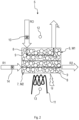
- a schematic view of one embodiment of a sorption filter device for the motor vehicle according to
Fig. 1 ; - Fig. 3
- a schematic perspective view of the sorption filter device according to
Fig. 2 ; - Fig. 4
- a further schematic perspective view of the sorption filter device according to
Fig. 2 ; - Fig. 5
- a schematic perspective exploded view of the sorption filter device according to
Fig. 2 ; - Fig. 6
- a schematic front view of the sorption filter device according to
Fig. 2 ; - Fig. 7
- a schematic side view of the sorption filter device according to
Fig. 2 ; - Fig. 8
- a cross-sectional view of the sorption filter device according to the sectional line IIX-IIX of
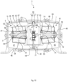
Fig. 7 ; - Fig. 9
- a further cross-sectional view of the sorption filter device according to the sectional line IX-IX of
Fig. 7 ; - Fig. 10
- a cross-sectional view of the sorption filter device according to the sectional line X-X of
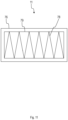
Fig. 7 ; and - Fig. 11
- a schematic view of one embodiment of a heater for the sorption filter device according to
Fig. 2 . - In the figures, identical or functionally identical elements have been given the same reference signs unless otherwise indicated.
-
Fig. 1 shows a schematic view of an embodiment of amotor vehicle 1. Themotor vehicle 1 is preferably an electric vehicle or a hybrid vehicle. However, themotor vehicle 1 may also be driven by means of an internal combustion engine. Themotor vehicle 1 comprises abody 2 which encloses anenclosed air volume 3. "Enclosed" in this context means that thebody 2 defines boundaries or a geometric extension of theenclosed air volume 3. However, this does not necessarily mean that theenclosed air volume 3 cannot be in air exchange with an environment U of themotor vehicle 1. - The
enclosed air volume 3 is an interior or passenger compartment of themotor vehicle 1. However, theenclosed air volume 3 may also be associated with a watercraft, a construction machine or a construction vehicle, a rail vehicle, an agricultural machine or an agricultural vehicle, or an aircraft. However, theenclosed air volume 3 may also be part of a building or a stationary machine. - In the following, however, it is assumed that the
enclosed air volume 3 is the passenger compartment of themotor vehicle 1. Therefore, theenclosed air volume 3 is hereinafter referred to as the passenger compartment. Thepassenger compartment 3 can be air conditioned by means of a heating, ventilation, and air conditioning (HVAC)system 4. To extend a range of such an electrically drivenmotor vehicle 1, it is desirable to save as much energy as possible. With reference to theHVAC system 4, this means that it should draw in as little fresh air as possible from the environment U of themotor vehicle 1 to air condition thepassenger compartment 3. - However, when recirculated air taken in the
passenger compartment 3 is used to air condition thepassenger compartment 3, water (H2O) contained in the exhaled air of occupants or passengers may accumulate in thepassenger compartment 3, which may cause windows, for example a windshield or side windows, of themotor vehicle 1 to fog. This must be avoided or at least reduced with regard to safety aspects. Furthermore, carbon dioxide (CO2) contained in the exhaled air can also accumulate in thepassenger compartment 3. This can lead to concentration problems or even health impairments for the occupants. This, too, must be prevented or at least reduced with regard to both safety and health aspects. -
Fig. 2 shows a schematic view of an embodiment of asorption filter device 5 for the combined reduction of CO2 and H2O, in particular water vapor, within thepassenger compartment 3. Thesorption filter device 5 is part of theHVAC system 4. With the aid of thesorption filter device 5, the previously mentioned disadvantages can be prevented or their effect at least reduced. In addition, thesorption filter device 5 can also be used to prevent impurities from the environment U from entering thepassenger compartment 3, since the preparation of the circulating air means that the intake of ambient air can be largely dispensed with. - The
sorption filter device 5 comprises a firstsorption filter apparatus 6 and a secondsorption filter apparatus 7. "Sorption" is a collective term for processes that lead to an accumulation of a substance within a phase or at an interface between two phases. The enrichment within a phase is more precisely called absorption, and that at the interface adsorption. This means that thesorption filter apparatuses sorption filter apparatuses sorption filter apparatuses - The
sorption filter apparatuses sorption filter apparatus 6 is in the sorption mode M1 when the secondsorption filter apparatus 7 is in the desorption mode M2 and vice versa. Thus, bothsorption filter apparatuses sorption filter apparatuses - Each
sorption filter apparatus first sorbent 8 and asecond sorbent 9. Preferably, thesorbents first sorbent 8 is suitable for adsorbing CO2. Accordingly, thesecond sorbent 9 may be suitable to adsorb H2O. The twosorbents passenger compartment 3. Thefirst sorbent 8 is illustrated with small circles. Thesecond sorbent 9 is illustrated with large circles. Other sorbents may also be provided, suitable for sorbing NOX or VOCs, for example. Thus, any number ofdifferent sorbents passenger compartment 3. - For example, in addition to the
sorbents sorbents first sorbent 8 and/or with thesecond sorbent 9 to build up one or more mixed bulk layers. - Furthermore, the
sorption filter apparatuses sorbents sorption filter apparatuses - The
sorbents sorbents sorption filter apparatuses - In
Fig. 2 , the firstsorption filter apparatus 6 is in the previously mentioned sorption mode M1. The secondsorption filter apparatus 7 is in the desorption mode M2. In the sorption mode M1, raw air RO loaded with CO2 and H2O from thepassenger compartment 3 is fed to the firstsorption filter apparatus 6. Afirst blower 10 may be provided for this purpose. The raw air RO is passed through the firstsorption filter apparatus 6 at least in sections, with thesorbents passenger compartment 3 as clean air RL. - The mechanism comprises a
heater 11. Theheater 11 is designed to supply heat Q either to the firstsorption filter apparatus 6 or to the secondsorption filter apparatus 7. In other words, theheater 11 can be switched between the firstsorption filter apparatus 6 and the secondsorption filter apparatus 7. By means of theheater 11, heat Q can be supplied to thesorbents heater 11 does not supply heat Q to the respectivesorption filter apparatus heater 11 supplies heat Q to the respectivesorption filter apparatus Fig. 2 , theheater 11 only supplies heat Q to the secondsorption filter apparatus 7, which is in the desorption mode M2, and not to the firstsorption filter apparatus 6 which is in the sorption mode M1. - The
heater 11 can be a PTC-heater (positive temperature coefficient). However, heat Q may also be introduced by any other means. For example, heat Q may be waste heat from an electric motor used to drive themotor vehicle 1. Heat Q may also be waste heat from a conventional internal combustion engine, a battery cooling system, or a fuel cell cooling circuit. Theheater 11 may also be a heat exchanger or comprise a heat exchanger.Thermocouples heater 11. There can be provided afirst thermocouple 12 that is assigned to the firstsorption filter apparatus 6 and asecond thermocouple 13 that is assigned to the secondsorption filter apparatus 7. - In the desorption mode M2, unloaded regeneration air R1 is supplied to the second
sorption filter apparatus 7 being loaded with CO2 and H2O. Asecond blower 14 can be used for this purpose. By the fact that the unloaded regeneration air R1 is "unloaded" with CO2 and H2O, it is to be understood that the unloaded regeneration air R1 can absorb CO2 and H2O stored in the secondsorption filter apparatus 7. That is, the unloaded regeneration air R1 may also have some content of CO2 and H2O. However, the unloaded regeneration air R1 is not saturated with CO2 and H2O. The unloaded regeneration air R1 can be taken from thepassenger compartment 3 or the environment U, for example. - When the
sorbents sorption filter apparatus 7, they release CO2 and H2O to the unloaded regeneration air R1. In other words, CO2 and H2O are desorbed. A temperature above 55 °C is preferably required for desorption. The unloaded regeneration air R1 is passed through the secondsorption filter apparatus 7, absorbs CO2 and H2O there and is discharged from the secondsorption filter apparatus 7 as loaded regeneration air R2. In particular, the loaded regeneration air R2 is supplied to the environment U. -
Fig. 3 shows a schematic perspective view of thesorption filter device 5 as explained before.Fig. 4 shows a further schematic perspective view of thesorption filter device 5.Fig. 5 shows a schematic perspective exploded view of thesorption filter device 5.Fig. 6 shows a schematic front view of thesorption filter device 5.Fig. 7 shows a schematic side view of thesorption filter device 5.Fig. 8 shows a cross-sectional view of thesorption filter device 5 according to the sectional line IIX-IIX ofFig. 7 .Fig. 9 shows a further cross-sectional view of thesorption filter device 5 according to the sectional line IX-IX ofFig. 7 .Fig. 10 shows a cross-sectional view of thesorption filter device 5 according to the sectional line X-X ofFig. 7 . In the following,Figs. 3 to 10 will be referred to at the same time. - The
sorption filter device 5 comprises ahousing 15 for receiving a removablesorption filter element 16. Thehousing 15 can have a rectangular cross-section. Thehousing 15 encompasses an inner space orinterior space 17. Thesorption filter element 16 is arranged within theinterior space 17. Thesorption filter element 16 comprises thesorption filter apparatuses heater 11 and thethermocouples sorption filter element 16 is exchangeable. Thesorption filter apparatuses sorption filter element 16 will be explained in detail later. - An inlet/
outlet apparatus 18 is attached to thehousing 15. The inlet/outlet apparatus 18 can be bolted to thehousing 15. A sealingelement 19 is positioned between thehousing 15 and the inlet/outlet apparatus 18. The sealingelement 19 can be made of rubber or polyurethane, for example. The sealingelement 19 seals the inlet/outlet apparatus 18 in a fluidtight manner against thehousing 15. - The inlet/
outlet apparatus 18 comprises a first inlet/outlet 20 and a second inlet/outlet 21. The first inlet/outlet 20 can be named upper inlet/outlet or top inlet/outlet. The second inlet/outlet 21 can be named lower inlet/outlet or bottom inlet/outlet. The inlets/outlets sorption filter element 16 via the first inlet/outlet 20 and clean air RL can be supplied to thepassenger compartment 3 via the second inlet/outlet 21. - The first inlet/
outlet 20 branches into twofluid channels interior space 17. The second inlet/outlet 21 branches into twofluid channels interior space 17. Thefluid channels fluid channels sorption filter element 16. Via thefluid channels sorption filter element 16 into thepassenger compartment 3. - The inlet/
outlet apparatus 18 has afirst flap 26 assigned to the first inlet/outlet 20 and asecond flap 27 assigned to the second inlet/outlet 21. Thefirst flap 26 is arranged within the first inlet/outlet 20. Thesecond flap 27 is arranged within the second inlet/outlet 21. Theflaps rotation shaft 28. Therotation shaft 28 is rotatably supported in the inlet/outlet apparatus 18. Therotation shaft 28 can be driven by means of adrive 29. Thedrive 29 can be an electric motor. Thefirst flap 26 comprises two plate-shapedarm sections second flap 27 comprises two plate-shapedarm sections first flap 26 can be named upper flap or top flap. Thesecond flap 27 can be named lower flap or bottom flap. - The
first flap 26 and thesecond flap 27 are both attached to therotation shaft 28 so that thedrive 29 can move bothflaps first flap 26 can either close thefluid channel 22 or thefluid channel 23. Thesecond flap 27 can either close thefluid channel 24 or thefluid channel 25. In other words, theflaps fluid channels fluid channels fluid channel 22 is open, thefluid channel 23 is closed. When thefluid channel 23 is open, thefluid channel 22 is closed. When thefluid channel 24 is open, thefluid channel 25 is closed. When thefluid channel 25 is open, thefluid channel 24 is closed. - The inlet/
outlet apparatus 18 further comprises anoutlet 34 for discharging the loaded regeneration air R2 into the environment U. Theoutlet 34 is fluidly connected to a window 35 (Fig. 9 ) that opens into thefluid channel 24 and to awindow 36 that opens into thefluid channel 25. When thesecond flap 27 closes thefluid channel 25, thesecond flap 27 also closes thewindow 35. When thesecond flap 27 closes thefluid channel 24, thesecond flap 27 also closes thewindow 36. In other words, when thefluid channel 24 is open, thewindow 36 is open. When thefluid channel 25 is open, thewindow 35 is open. - Now returning to the
sorption filter element 16, thesorption filter element 16 comprises aframe 37 and anend cap 38. Theframe 37 is connected to theend cap 38. Theframe 37 and theend cap 38 can be designed as an integral part. Theend cap 38 is suitable for closing thehousing 15 facing away from the inlet/outlet apparatus 18. Thesorption filter element 16 or theend cap 38 can be connected to thehousing 15 by means of attachingelements 39 of which only one is provided as a reference sign. - The
frame 37 comprises a separatingwall 40 that separates theinterior space 17 into twointerior space sections wall 40 is guided within thehousing 15 by means of twoguide tracks ceiling 45 and a bottom 46 of the housing. Theceiling 45 and the bottom 46 are connected to each other bysidewalls - The separating
wall 40 carries or supports theheater 11. Theheater 11 can be attached to the separatingwall 40. Theheater 11 is electrically connected to aplug 49 which protrudes out of theend cap 38. By means of theplug 49, theheater 11 can be energized. Theheater 11 is fluid permeable. That means that air, in particular unloaded regeneration air R1, can flow through theheater 11. For this purpose, theheater 11 can at least partly be grid shaped. - The
frame 37 further comprises afirst carrier 50 and asecond carrier 51. Thefirst carrier 50 and thesecond carrier 51 can be connected to each other. Thefirst carrier 50 carries twosorption filter bodies second carrier 51 carries twosorption filter bodies sorption filter bodies sorption filter apparatus 6. Thesorption filter bodies sorption filter apparatus 7. - The
first carrier 50 and thesecond carrier 51 encompass a firstintermediate space section 56 and a secondintermediate space section 57. Theintermediate space sections wall 40. Theintermediate space sections intermediate space 58 that is enclosed or encompassed by theframe 37, in particular by thecarriers second thermocouple 13 is arranged within the secondintermediate space section 57. Thefirst thermocouple 12 which is not shown inFig. 10 can be arranged within the firstintermediate space section 56. - Each
sorption filter body element 59 that seals against thefirst carrier 50 or thesecond carrier 51. The sealingelement 59 can be made of rubber, polyurethane or the like. Eachsorption filter body housing 60 that carries the sealingelement 59. The sealingelement 59 can be glued to thehousing 60. Thehousing 60 is square-shaped. Thehousing 60 is at least partly fluid permeable. Thehousing 60 encompasses a plurality of different sorptionfilter body sections housing 60. The sorptionfilter body sections different sorbents filter body sections filter body grid 65. The sorptionfilter body grid 65 can be named first grid. - The
sorption filter bodies carriers Fig. 5 ) of which only one is provided with a reference sign. Thecarriers protrusions filter body grids 65 of thesorption filter bodies sorption filter bodies carriers frame 37. - For exchanging the
sorption filter bodies elements 39 are opened, and thesorption filter element 16 is pulled out of thehousing 15. Then, thesorption filter bodies carriers sorption filter bodies - The functionality of the
sorption filter device 5 is explained in the following. In the sorption mode M1 of the firstsorption filter apparatus 6, theflaps fluid channels fluid channels window 35 is closed by means of thesecond flap 27. Thewindow 36 is open. Raw air RO is supplied to theinterior space 17 via the first inlet/outlet 20. In particular, the raw air RO is supplied to the firstinterior space section 41. - The raw air RO is passed through the first
sorption filter apparatus 6 and accordingly through thesorption filter bodies sorption filter apparatus 6 shown witharrows Fig. 10 . The raw air RO is filtered by means of the sorptionfilter body sections intermediate space 58 via the sorptionfilter body grids 65 of thesorption filter bodies intermediate space section 56. From the firstintermediate space section 56, the purified raw air RO is fed back to thepassenger compartment 3 as clean air RL via the second inlet/outlet 21 and thefluid channel 24. - While the first
sorption filter apparatus 6 is in the sorption mode M1, the secondsorption filter apparatus 7 comprising thesorption filter bodies fluid channels intermediate space section 57 of theframe 37. However, as theheater 11 is fluid permeable, clean air RL passes through theheater 11 as shown by anarrow 73. - The clean air RL is used as unloaded regeneration air R1 for regenerating the second
sorption filter apparatus 7. Thus, the clean air RL passes as unloaded regeneration air R1 through thesorption filter bodies arrows Fig. 10 . Since the unloaded regeneration air R1 passes theheater 11, heat Q is applied to the unloaded regeneration air R1. The unloaded regeneration air R1 passes through the sorptionfilter body grids 65 of thesorption filter bodies sorption filter device 5 via thewindow 36 and theoutlet 34 into the environment U. The unloaded regeneration air R1 supplies heat Q to thesorbents sorption filter bodies - To put the first
sorption filter apparatus 6 into the desorption mode M2 and the secondsorption filter apparatus 7 into the sorption mode M1, thedrive 29 is energized to close thefluid channels fluid channels flaps -
Fig. 11 shows one embodiment of aheater 11 as mentioned before. Theheater 11 can be a PTC-heater (positive temperature coefficient). Theheater 11 can comprise aframe 76 which can be made of plastic. Theframe 76 can also be made of a ceramic material. The separatingwall 40 carries theframe 76. A receiving section 77 (Fig. 10 ) is provided for this purpose at the separatingwall 40. - The
heater 11 comprises aheater grid 78 that is fluid permeable. Theheater grid 78 can be named second grid. Theframe 76 carries theheater grid 78. Theheater grid 78 can be made of a metallic material. Theheater grid 78 can be energized to supply heat Q to the unloaded regeneration air R1 that passes theheater grid 78. As mentioned before, clean air RL can be used as unloaded regeneration air R1. - The
frame 76 has awindow 79 that is covered by theheater grid 78. There can be more than onewindow 79. Thus, there can be also more than oneheater grid 78. The number ofwindows 79 is arbitrary. Theheater grid 78 can have zig-zag-shape as shown inFig. 11 . However, theheater grid 78 can also be mesh-like or lattice-like. Theheater 11 and in particular theheater grid 78 is fluid permeable so that the unloaded regeneration air R1 can pass theheater 11. -
- 1
- Motor vehicle
- 2
- Body
- 3
- Volume/passenger compartment
- 4
- HVAC system
- 5
- Sorption filter device
- 6
- Sorption filter apparatus
- 7
- Sorption filter apparatus
- 8
- Sorbent
- 9
- Sorbent
- 10
- Blower
- 11
- Heater
- 12
- Thermocouple
- 13
- Thermocouple
- 14
- Blower
- 15
- Housing
- 16
- Sorption filter element
- 17
- Interior space
- 18
- Inlet/outlet apparatus
- 19
- Sealing element
- 20
- Inlet/outlet
- 21
- Inlet/outlet
- 22
- Fluid channel
- 23
- Fluid channel
- 24
- Fluid channel
- 25
- Fluid channel
- 26
- Flap
- 27
- Flap
- 28
- Rotation shaft
- 29
- Drive
- 30
- Arm section
- 31
- Arm section
- 32
- Arm section
- 33
- Arm section
- 34
- Outlet
- 35
- Window
- 36
- Window
- 37
- Frame
- 38
- End cap
- 39
- Attaching element
- 40
- Separating wall
- 41
- Interior space section
- 42
- Interior space section
- 43
- Guide track
- 44
- Guide track
- 45
- Ceiling
- 46
- Bottom
- 47
- Sidewall
- 48
- Sidewall
- 49
- Plug
- 50
- Carrier
- 51
- Carrier
- 52
- Sorption filter body
- 53
- Sorption filter body
- 54
- Sorption filter body
- 55
- Sorption filter body
- 56
- Intermediate space section
- 57
- Intermediate space section
- 58
- Intermediate space
- 59
- Sealing element
- 60
- Housing
- 61
- Sorption filter body section
- 62
- Sorption filter body section
- 63
- Sorption filter body section
- 64
- Sorption filter body section
- 65
- Sorption filter body grid
- 66
- Snap hook
- 67
- Protrusion
- 68
- Protrusion
- 69
- Protrusion
- 70
- Protrusion
- 71
- Arrow
- 72
- Arrow
- 73
- Arrow
- 74
- Arrow
- 75
- Arrow
- 76
- Frame
- 77
- Receiving section
- 78
- Heater grid
- 79
- Window
- M1
- Sorption mode
- M2
- Desorption mode
- Q
- Heat
- R1
- Regeneration air
- R2
- Regeneration air
- RL
- Clean air
- RO
- Raw air
- U
- Environment
Claims (15)
- A sorption filter element (16) for a sorption filter device (5), the sorption filter element (16) comprising:a heater (11);a frame (37) enclosing an intermediate space (58) and comprising a separating wall (40) running through the intermediate space (58), the separating wall (40) being configured to receive the heater (11),wherein the heater (11) is configured to heat regeneration air (R1) within the intermediate space (58), and comprises a heater grid (78) through which the regeneration air (R1) flows; andone or more sorption filter bodies (52, 53, 54, 55) comprising at least one sorbent (8, 9), the one or more sorption filter bodies (52, 53, 54, 55) being configured to remove carbon dioxide (CO2) and/or water (H2O) from raw air (RO) to turn the raw air (RO) into clean air (RL), and each of the one or more sorption filter bodies (52, 53, 54, 55) comprising a sorption filter body grid (65) through which the clean air (RL) flows into the intermediate space (58) and through which the heated regeneration air (R1) flows out of the intermediate space (58).
- The sorption filter element (16) according to claim 1, wherein the one or more sorption filter bodies (52, 53, 54, 55) are disposed on respective opposing sides of the frame (37).
- The sorption filter element (16) according to claim 1 or 2, wherein the separating wall (40) is configured to be guided along guide tracks (43, 44) of a housing (15) of the sorption filter device (5) when moving the sorption filter element (16) out of the housing (15) and into the housing (15), and the sorption filter element (16) further comprises an end cap (38) configured to close the housing (15), the end cap (38) being attached to the frame (37).
- The sorption filter element (16) according to one of claims 1 - 3, wherein the heated regeneration (R1) air flows out of the intermediate space (58) into an environment (U) via an outlet (34).
- The sorption filter element (16) according to one of claims 1 - 4, wherein the separating wall (40) is disposed along a central portion of the intermediate space (58).
- The sorption filter element (16) according to one of claims 1 - 5, wherein the separating wall (40) partitions the intermediate space (58) into a first intermediate space section (56) and a second intermediate space section (57), and
the regeneration air (R1) flows through the heater grid (78) from the first intermediate space section (56) into the second intermediate space section (57) or vice versa. - The sorption filter element (16) according to one of claims 1 - 6, wherein the frame (37) comprises a first carrier (50) and a second carrier (51) configured to carry the one or more sorption filter bodies (52, 53, 54, 55), the first carrier (50) and the second carrier (51) enclosing the intermediate space (58).
- The sorption filter element (16) according to one of claims 1 - 7, wherein the frame (37) comprises protrusions (67, 68, 69, 70) configured to press against the sorption filter body grid (65).
- The sorption filter element (16) according to one of claims 1 - 8, further comprising two pairs of the one or more sorption filter bodies (52, 53, 54, 55), the two pairs respectively forming sorption filter apparatuses (6, 7) configured to be interchangeably brought from a sorption mode (M1) into a desorption mode (M2) and vice versa.
- The sorption filter element (16) according to claim 9, wherein each of the two pairs of the one or more sorption filter bodies (52, 53, 54, 55) is arranged in a V-configuration or a parallel configuration.
- A sorption filter device (5) comprising:the sorption filter element (16) according to one of claims 1 - 10; anda housing (15) configured to receive the sorption filter element (16).
- The sorption filter device (5) according to claim 11, further comprising an inlet/outlet apparatus (18) attached to the housing (15) and configured to:supply the raw air (RO) to the sorption filter element (16); andguide the clean air (RL) away from the sorption filter element (16).
- The sorption filter device (5) according to claim 12, wherein inlet/outlet apparatus (18) comprises an outlet (34) configured to discharge the heated regeneration air (R1) into an environment (U).
- The sorption filter device (5) according to claim 12 or 13, wherein the inlet/outlet apparatus (18) comprises a first inlet/outlet (20) and a second inlet/outlet (21), each of the first inlet/outlet (20) and the second inlet/outlet (21) branching into two fluid channels (22, 23, 24, 25), and the two fluid channels (24, 25) of the second inlet/outlet (21) being fluidly connected to the intermediate space (58).
- The sorption filter device (5) according to claim 14, wherein the inlet/outlet apparatus (18) further comprises movable flaps (26, 27) configured to alternate opening and closing one of the two fluid channels (22, 23) of the first inlet/outlet (20) and one of the two fluid channels (24, 25) of the second inlet/outlet (21).
Priority Applications (4)
| Application Number | Priority Date | Filing Date | Title |
|---|---|---|---|
| EP23184335.0A EP4491255B1 (en) | 2023-07-10 | 2023-07-10 | Sorption filter element and sorption filter device |
| US18/673,277 US20250018325A1 (en) | 2023-07-10 | 2024-05-23 | Sorption filter element and sorption filter device |
| KR1020240070474A KR20250009341A (en) | 2023-07-10 | 2024-05-30 | Sorption filter element and sorption filter device |
| CN202410922178.5A CN119281043A (en) | 2023-07-10 | 2024-07-10 | Adsorption filter element and adsorption filter equipment |
Applications Claiming Priority (1)
| Application Number | Priority Date | Filing Date | Title |
|---|---|---|---|
| EP23184335.0A EP4491255B1 (en) | 2023-07-10 | 2023-07-10 | Sorption filter element and sorption filter device |
Publications (2)
| Publication Number | Publication Date |
|---|---|
| EP4491255A1 true EP4491255A1 (en) | 2025-01-15 |
| EP4491255B1 EP4491255B1 (en) | 2026-04-01 |
Family
ID=87202101
Family Applications (1)
| Application Number | Title | Priority Date | Filing Date |
|---|---|---|---|
| EP23184335.0A Active EP4491255B1 (en) | 2023-07-10 | 2023-07-10 | Sorption filter element and sorption filter device |
Country Status (4)
| Country | Link |
|---|---|
| US (1) | US20250018325A1 (en) |
| EP (1) | EP4491255B1 (en) |
| KR (1) | KR20250009341A (en) |
| CN (1) | CN119281043A (en) |
Citations (2)
| Publication number | Priority date | Publication date | Assignee | Title |
|---|---|---|---|---|
| US5725639A (en) * | 1995-07-28 | 1998-03-10 | Bayerische Motoren Werke Aktiengesellschaft | Device for drying air for motor vehicles |
| US6478858B2 (en) * | 2000-01-13 | 2002-11-12 | Behr Gmbh & Co. | Desorbable sorption filter suitable for a motor vehicle heating or air-conditioning system |
Family Cites Families (4)
| Publication number | Priority date | Publication date | Assignee | Title |
|---|---|---|---|---|
| CN114288725B (en) * | 2016-03-18 | 2023-06-13 | 康明斯过滤Ip公司 | Interlocking stable filter assembly |
| US11141687B2 (en) * | 2016-05-02 | 2021-10-12 | Cummins Filtration Ip, Inc. | Filter with interlocking housing interface |
| JP6709773B2 (en) * | 2017-11-30 | 2020-06-17 | 本田技研工業株式会社 | Vehicle air purification device |
| JP7138578B2 (en) * | 2019-01-16 | 2022-09-16 | 本田技研工業株式会社 | vehicle air purifier |
-
2023
- 2023-07-10 EP EP23184335.0A patent/EP4491255B1/en active Active
-
2024
- 2024-05-23 US US18/673,277 patent/US20250018325A1/en active Pending
- 2024-05-30 KR KR1020240070474A patent/KR20250009341A/en active Pending
- 2024-07-10 CN CN202410922178.5A patent/CN119281043A/en active Pending
Patent Citations (2)
| Publication number | Priority date | Publication date | Assignee | Title |
|---|---|---|---|---|
| US5725639A (en) * | 1995-07-28 | 1998-03-10 | Bayerische Motoren Werke Aktiengesellschaft | Device for drying air for motor vehicles |
| US6478858B2 (en) * | 2000-01-13 | 2002-11-12 | Behr Gmbh & Co. | Desorbable sorption filter suitable for a motor vehicle heating or air-conditioning system |
Also Published As
| Publication number | Publication date |
|---|---|
| CN119281043A (en) | 2025-01-10 |
| EP4491255B1 (en) | 2026-04-01 |
| US20250018325A1 (en) | 2025-01-16 |
| KR20250009341A (en) | 2025-01-17 |
Similar Documents
| Publication | Publication Date | Title |
|---|---|---|
| CN113613921B (en) | Devices, motor vehicles and methods for the combined reduction of carbon dioxide and water or moisture content | |
| KR102267883B1 (en) | A device for purifying the CO2-filled air in the cabin of a car in recirculation-air mode by means of an adsorption device | |
| US11110386B2 (en) | Air purification device for vehicle | |
| US10646815B2 (en) | System and process for carbon dioxide removal of air of passenger cabins of vehicles | |
| US5938523A (en) | Device for removing the noxious and aromatic substances from an air flow fed into the interior of a vehicle | |
| EP4410402A1 (en) | Sorption filter cartridge and sorption filter element | |
| JPH0920133A (en) | Apparatus and method for treating an air stream supplied to a room | |
| JPH0948236A (en) | Air drying equipment | |
| CN111907287A (en) | Air conditioning system for vehicle and carbon dioxide collection module thereof | |
| CN106377975A (en) | Automotive air purifier and purification method thereof | |
| US20240091700A1 (en) | Sorption filter device | |
| EP4491255B1 (en) | Sorption filter element and sorption filter device | |
| EP4338992B1 (en) | Sorption filter element | |
| US12508533B2 (en) | Device and method for conditioning air in an enclosed space and vehicle comprising the device | |
| EP4609936A1 (en) | Sorption filter cartridge and sorption filter element | |
| EP4599919A1 (en) | Sorption filter, sorption filter cartridge and method for producing sorption filter | |
| EP4674506A1 (en) | Sorption filter element, sorption filter cartridge, and method of manufacturing sorption filter element | |
| US20260077289A1 (en) | Reduction of emissions in the vehicle interior | |
| JP4873950B2 (en) | Automotive air purification system |
Legal Events
| Date | Code | Title | Description |
|---|---|---|---|
| PUAI | Public reference made under article 153(3) epc to a published international application that has entered the european phase |
Free format text: ORIGINAL CODE: 0009012 |
|
| STAA | Information on the status of an ep patent application or granted ep patent |
Free format text: STATUS: THE APPLICATION HAS BEEN PUBLISHED |
|
| AK | Designated contracting states |
Kind code of ref document: A1 Designated state(s): AL AT BE BG CH CY CZ DE DK EE ES FI FR GB GR HR HU IE IS IT LI LT LU LV MC ME MK MT NL NO PL PT RO RS SE SI SK SM TR |
|
| STAA | Information on the status of an ep patent application or granted ep patent |
Free format text: STATUS: REQUEST FOR EXAMINATION WAS MADE |
|
| 17P | Request for examination filed |
Effective date: 20250704 |
|
| GRAP | Despatch of communication of intention to grant a patent |
Free format text: ORIGINAL CODE: EPIDOSNIGR1 |
|
| STAA | Information on the status of an ep patent application or granted ep patent |
Free format text: STATUS: GRANT OF PATENT IS INTENDED |
|
| INTG | Intention to grant announced |
Effective date: 20251030 |
|
| GRAS | Grant fee paid |
Free format text: ORIGINAL CODE: EPIDOSNIGR3 |
|
| GRAA | (expected) grant |
Free format text: ORIGINAL CODE: 0009210 |
|
| STAA | Information on the status of an ep patent application or granted ep patent |
Free format text: STATUS: THE PATENT HAS BEEN GRANTED |
|
| AK | Designated contracting states |
Kind code of ref document: B1 Designated state(s): AL AT BE BG CH CY CZ DE DK EE ES FI FR GB GR HR HU IE IS IT LI LT LU LV MC ME MK MT NL NO PL PT RO RS SE SI SK SM TR |
|
| REG | Reference to a national code |
Ref country code: CH Ref legal event code: F10 Free format text: ST27 STATUS EVENT CODE: U-0-0-F10-F00 (AS PROVIDED BY THE NATIONAL OFFICE) Effective date: 20260401 Ref country code: GB Ref legal event code: FG4D |
|
| REG | Reference to a national code |
Ref country code: IE Ref legal event code: FG4D |
|
| REG | Reference to a national code |
Ref country code: DE Ref legal event code: R096 Ref document number: 602023014341 Country of ref document: DE |
|
| REG | Reference to a national code |
Ref country code: NL Ref legal event code: MP Effective date: 20260401 |