EP4491154A2 - Capture devices for controlled release of prosthetic valve devices - Google Patents
Capture devices for controlled release of prosthetic valve devices Download PDFInfo
- Publication number
- EP4491154A2 EP4491154A2 EP24178261.4A EP24178261A EP4491154A2 EP 4491154 A2 EP4491154 A2 EP 4491154A2 EP 24178261 A EP24178261 A EP 24178261A EP 4491154 A2 EP4491154 A2 EP 4491154A2
- Authority
- EP
- European Patent Office
- Prior art keywords
- slot
- capture
- cover
- slots
- prosthetic valve
- Prior art date
- Legal status (The legal status is an assumption and is not a legal conclusion. Google has not performed a legal analysis and makes no representation as to the accuracy of the status listed.)
- Pending
Links
Images






Classifications
-
- A—HUMAN NECESSITIES
- A61—MEDICAL OR VETERINARY SCIENCE; HYGIENE
- A61F—FILTERS IMPLANTABLE INTO BLOOD VESSELS; PROSTHESES; DEVICES PROVIDING PATENCY TO, OR PREVENTING COLLAPSING OF, TUBULAR STRUCTURES OF THE BODY, e.g. STENTS; ORTHOPAEDIC, NURSING OR CONTRACEPTIVE DEVICES; FOMENTATION; TREATMENT OR PROTECTION OF EYES OR EARS; BANDAGES, DRESSINGS OR ABSORBENT PADS; FIRST-AID KITS
- A61F2/00—Filters implantable into blood vessels; Prostheses, i.e. artificial substitutes or replacements for parts of the body; Appliances for connecting them with the body; Devices providing patency to, or preventing collapsing of, tubular structures of the body, e.g. stents
- A61F2/02—Prostheses implantable into the body
- A61F2/24—Heart valves ; Vascular valves, e.g. venous valves; Heart implants, e.g. passive devices for improving the function of the native valve or the heart muscle; Transmyocardial revascularisation [TMR] devices; Valves implantable in the body
- A61F2/2427—Devices for manipulating or deploying heart valves during implantation
- A61F2/2439—Expansion controlled by filaments
-
- A—HUMAN NECESSITIES
- A61—MEDICAL OR VETERINARY SCIENCE; HYGIENE
- A61F—FILTERS IMPLANTABLE INTO BLOOD VESSELS; PROSTHESES; DEVICES PROVIDING PATENCY TO, OR PREVENTING COLLAPSING OF, TUBULAR STRUCTURES OF THE BODY, e.g. STENTS; ORTHOPAEDIC, NURSING OR CONTRACEPTIVE DEVICES; FOMENTATION; TREATMENT OR PROTECTION OF EYES OR EARS; BANDAGES, DRESSINGS OR ABSORBENT PADS; FIRST-AID KITS
- A61F2/00—Filters implantable into blood vessels; Prostheses, i.e. artificial substitutes or replacements for parts of the body; Appliances for connecting them with the body; Devices providing patency to, or preventing collapsing of, tubular structures of the body, e.g. stents
- A61F2/02—Prostheses implantable into the body
- A61F2/24—Heart valves ; Vascular valves, e.g. venous valves; Heart implants, e.g. passive devices for improving the function of the native valve or the heart muscle; Transmyocardial revascularisation [TMR] devices; Valves implantable in the body
- A61F2/2412—Heart valves ; Vascular valves, e.g. venous valves; Heart implants, e.g. passive devices for improving the function of the native valve or the heart muscle; Transmyocardial revascularisation [TMR] devices; Valves implantable in the body with soft flexible valve members, e.g. tissue valves shaped like natural valves
- A61F2/2418—Scaffolds therefor, e.g. support stents
-
- A—HUMAN NECESSITIES
- A61—MEDICAL OR VETERINARY SCIENCE; HYGIENE
- A61F—FILTERS IMPLANTABLE INTO BLOOD VESSELS; PROSTHESES; DEVICES PROVIDING PATENCY TO, OR PREVENTING COLLAPSING OF, TUBULAR STRUCTURES OF THE BODY, e.g. STENTS; ORTHOPAEDIC, NURSING OR CONTRACEPTIVE DEVICES; FOMENTATION; TREATMENT OR PROTECTION OF EYES OR EARS; BANDAGES, DRESSINGS OR ABSORBENT PADS; FIRST-AID KITS
- A61F2/00—Filters implantable into blood vessels; Prostheses, i.e. artificial substitutes or replacements for parts of the body; Appliances for connecting them with the body; Devices providing patency to, or preventing collapsing of, tubular structures of the body, e.g. stents
- A61F2/02—Prostheses implantable into the body
- A61F2/24—Heart valves ; Vascular valves, e.g. venous valves; Heart implants, e.g. passive devices for improving the function of the native valve or the heart muscle; Transmyocardial revascularisation [TMR] devices; Valves implantable in the body
- A61F2/2427—Devices for manipulating or deploying heart valves during implantation
- A61F2/2436—Deployment by retracting a sheath
-
- A—HUMAN NECESSITIES
- A61—MEDICAL OR VETERINARY SCIENCE; HYGIENE
- A61F—FILTERS IMPLANTABLE INTO BLOOD VESSELS; PROSTHESES; DEVICES PROVIDING PATENCY TO, OR PREVENTING COLLAPSING OF, TUBULAR STRUCTURES OF THE BODY, e.g. STENTS; ORTHOPAEDIC, NURSING OR CONTRACEPTIVE DEVICES; FOMENTATION; TREATMENT OR PROTECTION OF EYES OR EARS; BANDAGES, DRESSINGS OR ABSORBENT PADS; FIRST-AID KITS
- A61F2/00—Filters implantable into blood vessels; Prostheses, i.e. artificial substitutes or replacements for parts of the body; Appliances for connecting them with the body; Devices providing patency to, or preventing collapsing of, tubular structures of the body, e.g. stents
- A61F2/0095—Packages or dispensers for prostheses or other implants
-
- A—HUMAN NECESSITIES
- A61—MEDICAL OR VETERINARY SCIENCE; HYGIENE
- A61F—FILTERS IMPLANTABLE INTO BLOOD VESSELS; PROSTHESES; DEVICES PROVIDING PATENCY TO, OR PREVENTING COLLAPSING OF, TUBULAR STRUCTURES OF THE BODY, e.g. STENTS; ORTHOPAEDIC, NURSING OR CONTRACEPTIVE DEVICES; FOMENTATION; TREATMENT OR PROTECTION OF EYES OR EARS; BANDAGES, DRESSINGS OR ABSORBENT PADS; FIRST-AID KITS
- A61F2210/00—Particular material properties of prostheses classified in groups A61F2/00 - A61F2/26 or A61F2/82 or A61F9/00 or A61F11/00 or subgroups thereof
- A61F2210/0014—Particular material properties of prostheses classified in groups A61F2/00 - A61F2/26 or A61F2/82 or A61F9/00 or A61F11/00 or subgroups thereof using shape memory or superelastic materials, e.g. nitinol
Definitions
- the present invention relates generally to the treatment of cardiac valve disease using prosthetic valves, and more particularly to a delivery system for a prosthetic valve device configured to replace a native heart valve.
- Diseases associated with heart valves can include stenosis and valvular insufficiency or regurgitation.
- valvular stenosis causes the valve to become narrowed and hardened which can prevent blood flow to a downstream heart chamber from occurring at the proper flow rate and may cause the heart to work harder to pump the blood through the diseased valve.
- Valvular insufficiency or regurgitation occurs when the valve does not close completely, allowing blood to flow backwards, thereby causing the heart to be less efficient.
- a diseased or damaged valve which can be congenital, age-related, drug-induced, or in some instances, caused by infection, can result in an enlarged, thickened heart that loses elasticity and efficiency.
- Heart valve diseases can include weakness, shortness of breath, dizziness, fainting, palpitations, anemia and edema, and blood clots which can increase the likelihood of stroke or pulmonary embolism. Symptoms can often be severe enough to be debilitating and/or life threatening.
- Heart valve prostheses have been developed for repair and replacement of diseased and/or damaged heart valves.
- Such heart valve prostheses can be percutaneously delivered and deployed at the site of the diseased heart valve through catheter-based delivery systems.
- Such heart valve prostheses generally include a frame or stent and a prosthetic valve mounted within the frame.
- Such heart valve prostheses are delivered in a radially compressed or crimped configuration so that the heart valve prosthesis can be advanced through the patient's vasculature. Once positioned at the treatment site, the heart valve prosthesis is expanded to engage tissue at the diseased heart valve region to, for instance, hold the heart valve prosthesis in position.
- the energy dissipated can cause the valve to jump and can lead to movement and placement inaccuracy. Further, the heart valve prosthesis may experience backfolding or buckling during deployment.
- prosthetic valves e.g ., leaflets
- prosthetic valves are generally made of organic tissue, e.g. , bovine or porcine tissue, and require onsite installation onto a delivery device. This is due to the need to store the heart valve prostheses in conditions specific to preserve the organic tissue.
- a detailed process must be performed in order to install a heart valve prosthesis on a delivery device at the geographic location of the procedure ( e.g. , a hospital). The detailed process, however, can be cumbersome and costly due to the potential of damaging the heart valve prosthesis during the installation.
- a delivery system comprises an outer shaft including a capsule at a distal portion thereof, the capsule configured to restrain a prosthetic valve device therein, an inner shaft disposed within the outer shaft, and a first capture device disposed between the outer shaft and the inner shaft.
- the first capture device is configured to retain a portion of the prosthetic valve device.
- the first capture device comprises: a body including a central passage, a plurality of radial openings extending from the central passage radially outward to an outer surface of the body, and a plurality of slots in the outer surface of the body; and a plurality of capture loops, each capture loop extending radially outward through a corresponding radial opening, each capture loop configured to extend through a portion of the prosthetic valve device, and a distal end of each capture loop configured to be releasably restrained in a corresponding slot of the plurality of slots.
- the delivery system of any of the previous or subsequent examples herein further comprises a middle shaft, wherein the first capture device is coupled to the middle shaft.
- the first capture device further comprises a cover, the cover being rotatable between a first position in which the cover prevents the capture loops from escaping the slots and a second position in which the cover does not prevent at least some of the capture loops from escaping the slots.
- the cover in the delivery system of any of the previous or subsequent examples herein, includes at least one slot opening and at least one slot cover, wherein the cover is configured such that in the first position the at least one slot cover is aligned with a first slot of the plurality of slots and in the second position the at least one slot opening is aligned with the first slot of the plurality of slots.
- the body of the capture device includes a first quantity of slots
- the cover includes a second quantity of slot openings
- the cover includes a third quantity of slot covers.
- the first quantity, the second quantity, and the third quantity are equal such that in the first position each of the slot covers is aligned with a corresponding slot of the plurality of slots and in the second position each of the slot openings is aligned with a corresponding slot of the plurality of slots.
- the second quantity is one and the third quantity is one such that in the first position the slot cover is aligned with all of slots of the plurality of slots and in the second position the slot opening is aligned with first one of the plurality of slots and the slot cover is aligned with all of the plurality of slots except the first one.
- the cover in the delivery system of any of the previous or subsequent examples herein, includes additional positions such that in each of the additional positions the slot opening is aligned with a different one of the plurality of slots.
- the second quantity is less than the first quantity such that in the first position the slot covers are aligned with all of the slots and in the second position the slot openings are aligned with a plurality of the slots that is fewer than the first quantity, wherein cover includes additional positions such that in each of the additional positions the slot openings are aligned with different slots of the plurality of slots.
- the first capture device further comprises: a cover lumen extending radially from the central passage, wherein the cover lumen intersects with each of the plurality of slots between a first end of the slot and a second end of the slot; a cover disposed within the cover lumen and being rotatable relative to the body within the cover lumen, the cover including a plurality of slot openings and a plurality of slot covers; a plurality of springs, each spring of the plurality of springs coupled to the first end of a corresponding slot of the plurality of slots; and a plurality of flaps, each flap disposed at the second end of a corresponding slot of the plurality of slots; wherein in a first position, each slot cover of the plurality of slot covers is aligned with corresponding slot of the plurality of slots, each spring is in a compressed state such that each spring is disposed between a corresponding slot cover and the first end of the corresponding slot, and the dis
- the delivery system of any of the previous or subsequent examples further comprises a control shaft coupled to the cover, wherein the control shaft is configured to rotate the cover relative to the body of the capture device.
- the plurality of slots are L-shaped including a longitudinal portion and a circumferential portion, wherein the body is rotatable between a first position wherein the distal end of each capture loop is disposed in the circumferential portion of a corresponding slot and a second position wherein the distal end of each capture loop is aligned with the longitudinal portion of the corresponding slot.
- the delivery system of any of the previous or subsequent examples herein further comprises a pull wire coupled to proximal ends of the plurality of capture loops, wherein the pull wire is slidable within the outer shaft such that increased tension on the pull wire tightens the capture loops and decreased tension in the pull wire creates slack in the capture loops.
- the delivery system of any of the previous or subsequent examples herein further comprises a second capture device, wherein one of the first and second capture devices is a proximal capture device and the other of the first and second capture devices is a distal capture device, wherein the proximal capture device is configured to releasably retain a first end of the prosthetic valve device and the distal capture device is configured to releasably retain a second end of the prosthetic valve device.
- an implant assembly comprises an assembled configuration and an unassembled configuration.
- the implant assembly in the assembled configuration comprises a prosthetic valve device comprising a stent and a prosthetic valve coupled the stent, a first capture device coupled to a first end of the prosthetic valve device, and a second capture device coupled to a second end of the prosthetic valve device.
- the first capture device includes a capture body and a plurality of capture loops extending from the capture body through the first end of the prosthetic valve device and back to the capture body such that a distal end of each capture loop is releasably coupled to the capture body.
- the implant assembly in the assembled configuration is configured to be attached to a shaft of a delivery system.
- the prosthetic valve device is configured to be released from the first capture device and the second capture device after attachment to the shaft of the delivery system.
- the first capture device further comprises a cover, the cover being rotatable between a first position in which the cover prevents the capture loops from escaping the slots and a second position in which the cover does not prevent at least some of the capture loops from escaping the slots.
- the cover in the implant assembly of any of the previous or subsequent examples herein, includes at least one slot opening and at least one slot cover, wherein the cover is configured such that in the first position the at least one slot cover is aligned with a first slot of the plurality of slots and in the second position the at least one slot opening is aligned with the first slot of the plurality of slots.
- the body of the capture device includes a first quantity of slots
- the cover includes a second quantity of slot openings
- the cover includes a third quantity of slot covers.
- the first quantity, the second quantity, and the third quantity are equal such that in the first position each of the slot covers is aligned with a corresponding slot of the plurality of slots and in the second position each of the slot openings is aligned with a corresponding slot of the plurality of slots.
- the second quantity is one and the third quantity is one such that in the first position the slot cover is aligned with all of slots of the plurality of slots and in the second position the slot opening is aligned with first one of the plurality of slots and the slot cover is aligned with all of the plurality of slots except the first one.
- the cover in the implant assembly of any of the previous or subsequent examples herein, includes additional positions such that in each of the additional positions the slot opening is aligned with a different one of the plurality of slots.
- the second quantity is less than the first quantity such that in the first position the slot covers are aligned with all of the slots and in the second position the slot openings are aligned with a plurality of the slots that is fewer than the first quantity, wherein cover includes additional positions such that in each of the additional positions the slot openings are aligned with different slots of the plurality of slots.
- the first capture device further comprises: a cover lumen extending radially from the central passage, wherein the cover lumen intersects with each of the plurality of slots between a first end of the slot and a second end of the slot; a cover disposed within the cover lumen and being rotatable relative to the body within the cover lumen, the cover including a plurality of slot openings and a plurality of slot covers; a plurality of springs, each spring of the plurality of springs coupled to the first end of a corresponding slot of the plurality of slots; and a plurality of flaps, each flap disposed at the second end of a corresponding slot of the plurality of slots; wherein in a first position, each slot cover of the plurality of slot covers is aligned with corresponding slot of the plurality of slots, each spring is in a compressed state such that each spring is disposed between a corresponding slot cover and the first end of the corresponding slot, and the dis
- proximal and distal herein are used with reference to the clinician using the devices. Therefore, “proximal” and “proximally” mean in the direction toward the clinician, and “distal” and “distally” mean in the direction away from the clinician. In other words, “proximal” and “proximally” mean in the direction towards the handle of the delivery system and “distal” and “distally” mean in the direction towards the distal tip of the delivery system.
- the principles of the invention may be practiced in any instance in which it is desired to deliver a medical device intraluminally to a desired anatomic site.
- the invention will generally be described in the context in which the medical device being loaded onto a delivery system and delivered intraluminally is a prosthetic valve.
- the prosthetic valve is an infundibular reducer device configured to be implanted in the right ventricular outflow tract or the infundibulum, and corresponding embodiments of the invention are particularly useful for delivering the infundibular reducer device to the right ventricular outflow tract.
- the prosthetic valve device may be used in anatomic locations other than the infundibulum, such as the right ventricular outflow tract and other locations in or near the heart.
- the purpose of such devices is to allow replacement or prosthetic valves, such as pericardial heart valves, for example, having a smaller diameter than the diameter of the implanted site (e.g., the right ventricular outflow tract) to be implanted.
- the implanted site e.g., the right ventricular outflow tract
- other uses of the claimed invention such as to deliver different medical devices to different locations in the body, are contemplated and are not limited to those discussed in the application.
- FIG. 1 is a side view of an exemplary prosthetic valve device 150 that may be deployed using embodiments of delivery systems described herein, while FIGS. 1A and 1B are perspective and end views, respectively, of the prosthetic valve device 150.
- the prosthetic valve device 150 is merely exemplary. It is understood that any number of alternate devices can be used with the delivery devices and methods described herein. For example, U.S. Patent No. 8,801,776 to House et al. , which is incorporated by reference herein in its entirety, describes a device that may be delivered by delivery systems described herein. Similarly, the prosthetic valve devices described in U.S. Patent Application Publication No.
- the prosthetic valve device 150 is the Medtronic HARMONY TM transcatheter pulmonary valve.
- the delivery systems described herein may also be used with other self-expanding prostheses such as other prosthetic heart valves, stent-graft prostheses, uncovered stents, bare metal stents, drug eluting stents, and any self-expanding structure.
- prosthetic valve device 150 includes an expandable stent or frame 152 that supports a prosthetic valve component 153 within the interior of the stent 152.
- the stent 152 is self-expanding or self-expandable to return to a radially expanded configuration from a radially compressed or constricted radially compressed configuration.
- the prosthetic valve device 150 is compressible to be mounted into a delivery system and expandable to fit a desired body lumen, such as the right ventricular outflow tract, for example. In the embodiment depicted in FIG.
- the stent 152 has an expanded, longitudinally asymmetric hourglass configuration including three longitudinal sections or portions of a relatively enlarged first end 156, a relatively enlarged second end 158, and a midportion 155 extending between the first and second ends 156, 158.
- the first end 156 may also be referred to herein as the proximal or inflow end
- the second end 158 may also be referred to herein as the distal or outflow end.
- the midportion 155 is generally cylindrical in shape with a smaller diameter than the first and second ends 156, 158.
- the prosthetic valve component 153 is mounted within the midportion 155.
- Each longitudinal section or portion of stent 152 may be designed with a number of different configurations and sizes to meet the different requirements of the location in which it may be implanted.
- Each longitudinal section or portion of the stent 152 may have the same or different cross-portion which may be for example circular, ellipsoidal, rectangular, hexagonal, rectangular, square, or other polygonal shape, although at present it is believed that circular or ellipsoidal may be preferable when the prosthetic valve device is being provided for replacement of the aortic or mitral valve.
- the stent 152 may have a symmetric hourglass configuration, a generally tubular configuration, or other stent configuration or shape known in the art for valve replacement.
- the example prosthetic device 150 also includes a plurality of first attachment members 157 on or near the first end 156 and a plurality of second attachment members 159 on or near the second end 158. More particularly, a first attachment member 157 is attached to each endmost crown 151A on or near the first end 156 and a second attachment member 159 is attached to each endmost crown 151B on or near the second end 158. Thus, the number of total attachment members are dependent upon the design and configuration of the prosthetic valve device 150, and thus may be higher or lower than shown in the embodiment of FIG. 1 .
- Each attachment member of the first and second attachment members 157, 159 define an opening. Such attachment members may be loops formed from sutures, may be formed from the material used to form part of the stent 152, or other materials.
- FIG. 2 is a side view of a delivery system 100 according to embodiments hereof.
- the delivery system 100 is configured to receive and retain the prosthetic valve device 150 using a retention system (e.g., a proximal capture device 122 and/or a distal capture device 128, collectively referred to as capture devices 230) and percutaneously deliver the prosthetic valve device 150 in a compressed or radially compressed configuration to a treatment site in situ.
- a retention system e.g., a proximal capture device 122 and/or a distal capture device 128, collectively referred to as capture devices 230
- the delivery system 100 includes a proximal capture device 122 configured to engage or attach to the plurality of first attachment members 157 on or near the first end 156 of the prosthetic valve device 150 and a distal capture device 128 configured to engage or attach to the plurality of second attachment members 159 on or near the second end 158 of the prosthetic valve device 150.
- each capture device 230 generally includes a plurality of capture loops 225 configured for engagement with the prosthetic valve device 150 through respective attachment members 157 or 159.
- Each capture loop 225 is releasably retained within a respective slot 123 of the capture device 230 and is releasable from the respective slot 123 upon release of the prosthetic valve device 150.
- FIG. 2 illustrates the delivery system 100 disposed over a guidewire 109 for illustrative purposes only.
- FIG. 2A is a schematic drawing of delivery system 100.
- the guidewire 109 may be initially introduced into the target treatment site through a suitable body lumen to properly locate the desired position for the prosthetic valve device 150. The remainder of the delivery system 100 may then be guided along the guidewire 109 and into the site.
- the guidewire 109 may be, for example a 0.089 cm extra stiff guidewire as manufactured by Ampliated, Golden Valley, Minn., U.S.A.
- the delivery system 100 includes a distal end generally designated by the reference numeral 102 and a proximal end generally designated by the reference number 104.
- the proximal end 104 of the delivery system 100 remains outside of the patient, and the distal end 102 is inserted into the patient and is delivered intravascularly to an area at or near a pulmonary valve inside the body. Other uses for the delivery system 100 in other areas of the body, however, are also contemplated.
- the proximal end 104 includes means for remotely controlling the distal end 102 of the delivery system 100, in particular relating to deploying or releasing the prosthetic valve device 150 from the delivery system 100 in situ.
- the components of the proximal end 104 of the delivery system 100 may include those shown in FIGS. 2 and 2A , although additional and/or alternative components are also contemplated.
- the proximal end 104 may include a first rotating homeostasis valve 106, a side access port 108, an optional second rotating homeostasis valve (not shown), and a handle 170 including a guidewire lumen inlet 112.
- the first rotating homeostasis valve 106 grips or forms a fluid seal around an outer surface of the delivery system 100 to prevent blood or other fluid from leaking out of the delivery device at the proximal end or entry site into a patient and is configured to allow wires, devices and fluid to pass through.
- first rotating homeostasis valve 106 may also control the components of the distal end as described in more detail below by rotation of a portion of the first rotating homeostasis valve 106.
- the side access port 108 is provided as a means for injecting contrast media or saline, for example, into the delivery system 100.
- the second rotating homeostasis valve also prevents blood or other fluid from leaking back through the delivery system 100 and is configured to allow wires, devices, and fluid to pass through.
- the handle 170 controls the components of the distal end 102 as described in more detail below by independent manipulation of two portions of the handle 170.
- Other alternative or additional components of the proximal end 104 of the delivery system 100 are also contemplated by the claimed invention.
- FIG. 2B shows a cross-sectional view of the delivery system 100 of FIG. 2 taken along line A-A of FIG. 2 .
- the delivery system 100 includes at least three concentric tubular components, while the embodiment shown in FIG. 2B includes four concentric tubular components. More particularly, the delivery system 100 includes an inner shaft 114 which defines a guidewire lumen 115, a control shaft 210 which defines a control shaft lumen 121 and is slidingly disposed over the inner shaft 114, a middle shaft 140 which defines a middle shaft lumen 142 and is slidingly disposed over the control shaft 210, and an outer shaft 120 which includes an outer sheath or capsule 126 and defines a lumen 127 and is slidingly disposed over the middle shaft 140.
- the outer shaft 120 or the capsule 126 coupled to a distal end of the outer shaft 120 is configured to hold the prosthetic valve device 150 in a radially collapsed or compressed configuration during delivery.
- the middle shaft 140 may operate as a control shaft, thereby reducing the number of tubular components to three ( e.g ., the inner shaft 114, the middle shaft 140 and the outer shaft 120) instead of the four tubular components ( i.e. , the inner shaft 114, the control shaft 210, the middle shaft 140 and the outer shaft 120) illustrated in FIG. 2B .
- the delivery system 100 may further include at least one pull wire 220, described in further detail below.
- the delivery system 100 may further include an outer sleeve 116 that is disposed over a proximal portion of the outer shaft 120 to keep blood from leaking back around the delivery system 100.
- the inner shaft 114 may include the tapered distal tip 118 attached thereto at its distal end and may be attached to the guidewire lumen inlet 112 at its proximal end such that the inner shaft 114 may be tracked over the guidewire 109.
- the inner shaft 114 may be independently advanced or retracted through other components of the delivery system 100 by moving the guidewire lumen inlet 112 to which it is attached.
- the tapered distal tip 118 serves to ease the passage of the delivery system 100 through the vasculature.
- the middle shaft 140 is slidingly disposed over the inner shaft 114 and may be independently retractable with respect to the other shaft components of the delivery system 100.
- the distal capture device 128 is coupled to a distal end of the middle shaft 140.
- both the distal capture device 128 and proximal capture device 122 are coupled to middle shaft 140, where the distal capture device 128 is coupled to the distal end of the middle shaft 140 and proximal capture device 122 is coupled to the middle shaft 140 proximal to where the distal capture device 128 is coupled to the middle shaft 140.
- the outer shaft 120 includes the retractable sheath or capsule 126 coupled to the distal end of the outer shaft 120.
- the outer shaft 120 is retractable via a retraction mechanism such as a knob of the first rotating homeostasis valve 106, thereby also retracting the capsule 126.
- a retraction mechanism such as a knob of the first rotating homeostasis valve 106
- Various other retraction mechanisms may be used, such as an axially slidable lever, a rotatable rack and pinion gear, or other known mechanisms. In this way, the outer shaft 120 and capsule 126 are retractable relative to the inner shaft 114 and the middle shaft 140 during deployment of the prosthetic valve device 150.
- the proximal and distal capture devices 122, 128 are pre-loaded onto or pre-connected to the prosthetic valve device 150 forming an implant assembly 240.
- the pre-connection of the proximal and distal capture devices 122, 128 to the prosthetic valve device 150 may occur at the manufacturer's site, thereby ensuring that the prosthetic valve device 150 is properly connected to the proximal and distal capture devices 122, 128. In other embodiments, the pre-connection of the proximal and distal capture devices 122, 128 to the prosthetic valve device 150 may occur at the geographic location of the prosthetic valve device implantation ( e.g ., hospital). As shown in FIG.
- the implant assembly 240 (i.e., the prosthetic valve device 150 and the proximal and distal capture devices 122, 128) may be stored in a storage container 242, such as ajar, for shipment to the geographic location of the implantation procedure.
- the storage container 242 includes a preserving fluid.
- the preserving fluid can be any type of fluid that maintains the integrity and quality of the implant assembly 240.
- the prosthetic valve device 150 includes organic material
- the preserving fluid may include glutaraldehyde, formaldehyde, or other suitable preserving fluids to maintain the integrity of the organic material.
- the implant assembly 240 when ready for the implantation procedure, may be removed from the storage container 242 at the geographic location of the implantation procedure, as shown in FIG. 3B .
- the proximal capture device 122 is aligned with the distal end 102 of the delivery system 100.
- the implant assembly 240 and the delivery system 100 are then moved relative to one another such that the implant assembly 240 is loaded over the inner shafts of the delivery system 100 ( e.g. , the inner shaft 114 and the middle shaft 140), as shown in FIG. 3B .
- the implant assembly 240 is then connected to the delivery system 100, as shown in FIG. 3C .
- the implant assembly 240 may be connected to the delivery system 100 via a snap fit connection between the proximal capture device 122 and/or the distal capture device 128 and the shaft over which the proximal and distal capture devices 122, 128 are disposed, such as the middle shaft 140.
- the middle shaft 140 may include one or more bumps or protrusions extending outwardly from an outer surface thereof.
- the proximal capture device 122 and/or the distal capture device 128 may include a corresponding one or more indentations.
- the proximal capture device 122 and/or the distal capture device 128 may be forced over the one or more protrusions until the one or more protrusions extend into the corresponding one or more indentations, thereby attaching the implant assembly 240 to the middle shaft 140.
- the implant assembly 240 is then ready for further loading and delivery, as explained below.
- the proximal and distal capture device 122, 128 may be pre-attached to the prosthetic valve 150 and to a portion of the middle shaft 140 such that the implant assembly 240 includes the proximal and distal capture device 122, 128, the prosthetic valve device 150, and the portion of the middle shaft 140.
- the implant assembly 240 may then be attached to the delivery system 100 by attaching the portion of the middle shaft 140 to the remainder of the middle shaft 140.
- the connection may be a snap-fit connection, a threaded connection, a hinged connection, or other suitable connections known to those skilled in the art.
- the distal tip 118 may be initially unattached to the inner shaft 114 such that when inserting the inner shaft 114/middle shaft 140 through the implant assembly 240, the distal tip 118 is not attached to the inner shaft 114. This enables the proximal and distal capture device 122, 128 to slide over the inner shaft 114, whereas sliding the proximal and distal capture device 122, 128 over the distal tip 118 may be difficult due to the size of the distal tip 118.
- the distal tip 118 can be attached to the inner shaft 114 after the implant assembly 240 has been attached to the inner shaft 114/middle shaft 140.
- the distal tip 118 may be attached to the inner shaft 114 via a snap-fit connection, a threaded connection, or other suitable connections known to those skilled in the art. In other embodiments the distal tip 118 may be integrated into the distal capture device 128 of the implant assembly 240 such that when the implant assembly 240 is coupled to the delivery system 100, the distal tip 118 is also coupled to the delivery system 100.
- the prosthetic valve device 150 may be coupled to the delivery system 100 at the geographic location of the implantation procedure.
- distal tip 118, the inner shaft 114, and the middle shaft 140 are inserted through the prosthetic valve device 150 such that the prosthetic valve device 150 is disposed over the inner and middle shafts 114, 140 and between the proximal capture device 122 and the distal capture device 128, as shown in FIG. 4 .
- the proximal capture device 122 is coupled to the first end 156 of the prosthetic valve device 150 by looping a plurality of capture loops 225A through corresponding openings in the plurality of first attachment members 157, and the distal capture device 128 is coupled to the second end 158 of the prosthetic valve device 150 by looping, or otherwise engaging, a plurality of capture loops 225B through corresponding openings in the plurality of second attachment members 159, as shown in FIG. 4 .
- the first and second ends 156, 158 of the prosthetic valve device 150 may then be radially compressed, as shown in FIGS. 5 and 6 .
- the first and second ends of the prosthetic valve device 150 may be radially compressed by applying tension to the capture loops 225A, 225B, such as by use of a pull wire 220, described below.
- the pull wire 220 extends proximally to the handle 170, where tension on the pull wire 220, and hence the corresponding capture loops 225A or 225B, may be increased or decreased.
- the method of loading described herein includes attaching the first end 156 of the prosthetic valve device 150 to the delivery system 100 prior to attaching the second end 158 of the prosthetic valve device 150 to the delivery system, the order may be reversed and the second end 158 may be attached prior to the first end 156.
- a loading funnel 560 is used to further compress the prosthetic valve device 150 for eventual enclosure in the delivery system 100.
- the loading funnel 560 Prior to loading the prosthetic valve device 150 onto delivery system 100, the loading funnel 560 is disposed over the capsule 126 proximal of the proximal capture device 122.
- the loading funnel 560 may be disposed over the capsule 150 by sliding the loading funnel 560 proximally over the distal tip 118 and the capsule 126. In other embodiments, the loading funnel 560 may include two parts that are coupled together over the capsule 126.
- FIG. 7 is a side perspective view of the delivery system 100 with the prosthetic valve device 150 completely collapsed or enclosed within the loading funnel 560.
- FIG. 8 shows the distal end 102 of the delivery system 100 as it can be inserted intraluminally to a desired anatomic site for delivery of the prosthetic valve device 150.
- the capsule 126 contains the collapsed prosthetic valve device 150 in order to compress the prosthetic valve device 150 to have a profile reduced enough to be inserted into a desired anatomic site and to provide a smooth profile for insertion.
- the loading funnel 560 has been removed from the delivery system 100 by distally advancing the loading funnel 560 until it is removed from the delivery system 100.
- the capsule 126 In order to deploy or release the prosthetic valve device 150 once it has been positioned at its desired location in situ in the vasculature or in a heart valve annulus, for example, the capsule 126 is either retracted proximally, or the assembly of the middle shaft 120, the inner shaft 114, and the prosthetic valve device 150 is pushed out the distal end of the capsule 126.
- FIG. 9 shows deployment of the prosthetic valve device 150 is initiated via retraction of the capsule 126.
- FIG. 9 is a side perspective view of the delivery system 100 in which the capsule 126 is partially retracted to expose at least the second end 158 of the prosthetic valve device 150 and the exposed length of the prosthetic valve device 150 is partially expanded.
- the second end 158 of the prosthetic valve device 150 is still engaged or attached to the distal capture device 128 of the delivery system 100.
- the capsule 126 is shown as only partially retracted, an operator may retract the capsule 126 to expose the entire length of the prosthetic valve device 150. At this stage of deployment, positioning of the delivery system 100 may still be adjusted and/or the capsule 126 may be distally advanced to recapture the prosthetic valve device 150.
- the second end 158 of prosthetic valve device 150 may essentially be controlled via the distal capture device 128.
- tension on the capture loops 225B may be controlled, such as by the pull wire 220, such that the profile thereof of the prosthetic valve device may be sufficiently reduced to enable the capsule 126 to be distally advanced to recapture the prosthetic valve device 150 and thus allow repositioning thereof in situ.
- FIG. 10 shows the second end 158 of the prosthetic valve device 150 with tension on the capture loops 225B loosened such that the second end 158 is permitted to radially expand.
- the capture loops 225B have not been released from the prosthetic valve device 150.
- tension could be re-applied to radially compress the second end 158 of the prosthetic valve device 150 for recapture and re-positioning thereof, if desired.
- the second end 158 of the prosthetic valve device 150 is released from the distal capture device 128 and permitted to self-expand, as shown in FIG. 11 . More particularly, the distal capture loops 225B are released from slots 123 in the distal capture device 128 (see FIGS 14-15 ), and the second attachment members 159 of the prosthetic valve device 150, thereby releasing the second end 158 of the prosthetic valve device 150 from the delivery system 100.
- the capsule 126 is fully retracted to expose an entire length of the prosthetic valve device 150, with the first end 156 of the prosthetic valve device 150 still engaged or attached to the proximal capture device 122 of the delivery system 100. However, as stated above, the capsule 126 may have been fully retracted to expose an entire length of the prosthetic valve device 150 prior to releasing the second end 158 of the prosthetic valve device 150 from the proximal capture device 128.
- FIG. 12 shows a close-up view of the distal end 102 of the delivery system 100 with the prosthetic valve device released therefrom.
- the control shaft 210 may control portions of the capture devices 230 to release the capture loops 225 from the slots 123.
- the middle shaft 140 may control portions of the capture devices 230 to release the capture loops 225 from the slots 123.
- expansion of the prosthetic valve device 150 releases the capture loops 225 from the slots 123 of the capture devices 230.
- the capture loops 225 may comprise shape memory material such that the capture loops 225 release themselves from the slots 123 upon release of a force holding the capture loops in the slots 123.
- FIGS. 14-20 illustrate various embodiments of the capture device 230.
- the capture devices 230 described with respect to FIGS. 14-20 may be used as the proximal capture device 122 and/or the distal capture device 128 of the delivery system 100.
- the proximal capture device 122 may be one embodiment of a capture device 230 and the distal capture device 128 may be a different embodiment of a capture device 230.
- FIGS. 14 and 15 show an embodiment of a capture device 230.
- the capture device 230 shown in FIGS. 14 and 15 can be used as the proximal capture device 122 and/or the distal capture device 128.
- FIG. 14 shows the capture device 230 in a first or engaged position
- FIG. 15 shows the capture device 230 in a second or disengaged position.
- the capture device 230 includes a includes a body 232, a central passage 234, plurality of slots 123, and a plurality of capture loops 225, where each capture loop 225 is releasably retained within a corresponding slot 123 of the capture device 230.
- the body 232 includes a first end surface 231, a second end surface 233 opposite the first end surface 231, and an outer surface 235 between the first end surface 231 and the second end surface 233.
- the body 232 is generally cylindrically shaped, but that is not meant to be limiting.
- the capture device 230 further includes a plurality of openings 227 extending from the central passage 234 to an outer surface 235 of the body 232.
- the capture loops 225 may be connected to each other proximal of the capture device 230 to a pull wire 220, which runs proximally to the handle 170 of the delivery system 100, either through the control shaft lumen 121 or the middle shaft lumen 142, or other appropriate lumen.
- the capture loops 225 extend distally into the central passage 234 of the body 232, out of corresponding openings 227, and loop through a portion of the prosthetic valve device (e.g., the first attachment members 157 or the second attachment members 159) and into the corresponding slots 123.
- the slots 123 include a slot opening 1124 at the first end 231 of the body 232.
- slits 1123 in the outer surface 235 of the body 232 open into the slots 123.
- the slot openings 1124 are sized such that enlarged ends 259 of the capture loops 225 may enter and exit the slots 123 via the slot openings 1124.
- the slits 1123 are sized such that the enlarged ends 259 cannot enter or exit the slots 123 via the slits 1123.
- tension on the pull wire 220 tightens the capture loops 225 and decreased tension on the pull wire 220 loosens the capture loops 225. Moreover, according to embodiments herein, tension on the pull wire 220 is increased during loading to tighten capture loops 225 to reduce the diameter of the prosthetic valve device 150 where the capture loops 225 are coupled thereto. Further, tension on the pull wire 220 is decreased during implant deployment to create slack in the capture loops 225 and gradually allow the crowns of the prosthetic valve device 150 to expand, until the prosthetic valve device 150 is fully expanded.
- the capture loops 225 may be released from the slots 123 via expansion of the prosthetic valve device 150, via shape memory, and/or via articulation of the control shaft 210 or the middle shaft 140, as explained in various embodiment below.
- capture loops 225 may be polymeric (e.g., sutures), metallic, or other suitable materials.
- the proximal capture device 122 and the distal capture device 128 have adjustable-length capture loops 225.
- the capture loops 225 are adjustable via the pull wire 220, as shown in IFGS. 14 and 15.
- the capture loops 225 are fixed length such that a first end of each capture loop 225 may be attached to the body 232 and the second end of each capture loop 225 is inserted into the corresponding slot 123.
- both the proximal capture device 122 and the distal capture device 128 have adjustable-length capture loops 225.
- only the distal capture device 128 includes adjustable-length capture loops 225, and the proximal capture device 122 includes fixed-length capture loops 225.
- FIG. 14 shows the capture device 230 in a first or engaged position
- FIG. 15 shows the capture device 230 in a second or disengaged position
- the capture loops 225 exit the openings 227 radially outwardly, loop through a portion of the prosthetic valve device (e.g., first or second attachment members 157, 159, not shown in FIGS. 14 and 15 ), and back into the slots 123.
- the ends 259 of the capture loops 225 are released from the slots 123, such that the prosthetic heart valve device 150 is released from the delivery system 100.
- the capture loops are released from the slots 123 either by expansion of the prosthetic valve device 150 pulling the capture loops 225 out of the slots 123, or by making the capture loops 225 from a shape memory material and pre-setting the shape of the capture loops 225 to the second or disengaged position of FIG. 15 .
- the capture loops 225 return to the second position of FIG. 15 , thereby releasing the prosthetic valve device 150.
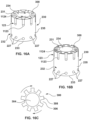
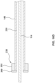
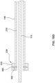
- FIGS. 16A-16C show a capture device 230 according to another embodiment herein.
- the capture loops 225 are not shown in FIGS 16A-16C for clarity but may be the capture loops 225 described with respect to FIGS. 14 and 15 .
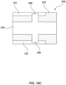
- the capture device 230 of FIGS. 16A-16C includes the body 232, the central passage 234, the slots 123, and the openings 227 as described above. Further, the capture device 230 of FIGS. 16A-16C includes a cover 300 disposed at or coupled to the first longitudinal end surface 231 of the body 232. The cover 300 is shown in greater detail in FIG.
- 16C and includes a body 302, a central longitudinal opening 304 extending through the center of the body 302, a plurality of slot openings 306 extending through the body 302 and evenly distributed radially around central longitudinal opening 304.
- the plurality of slot openings 306 further define edges of a plurality of slot covers 308 evenly radiating outward from central longitudinal opening 304 and formed from the portion of the body 302 occupying the space between each slot opening 306.
- the body 302 is disposed at the first longitudinal end surface 231 of the body 232 and centered on the body 232 such that the central longitudinal opening 304 is aligned with the central passage 234 of the body 232.
- the cover 300 is rotatable relative to the body 302.
- the cover 300 may be operatively coupled to the control shaft 210 such that rotation of the control shaft 210 (e.g., by rotating a handle actuator) rotates the body 302 of the cover 300 relative to the body 232.
- the cover 300 is configured to be rotated to two distinct positions relative to the body 232 of the capture device 230.
- FIG. 16A illustrates the cover 300 in a first position
- FIG. 16B illustrates the cover 300 in a second position.
- each slot cover 308 covers a corresponding slot opening 1124 of the body 232.
- the slot covers 308 prevent the enlarged ends 259 of the capture loops 225 from exiting the slots 123 through the slot openings 1124.
- each slot opening 306 aligns with a corresponding slot opening 1124 of the capture device 230.
- the ends 259 of the capture loops 225 may escape the slots 123 through the slot openings 1124 of the capture device 230 and the slot openings 306 of the cover 300.
- FIG. 17A shows a capture device 230 according to another embodiment herein.
- the capture loops 225 are not shown in FIG. 17A for clarity but may be the capture loops 225 described with respect to FIGS. 14 and 15 .
- the capture device 230 of FIG. 17A is similar to the capture device 230 of FIG. 16A such that like features will not be described again.
- the capture device 230 of FIG. 17A includes the body 232, the central passage 234, the slots 123, and the openings 227 as described above.
- the capture device 230 of FIG. 17A includes the cover 300 disposed at or coupled to the first longitudinal end surface 231 of the body 232. However, in the embodiment of FIG. 17A , the cover 300 includes a single slot opening 306.
- the cover 300 is rotatable relative to the body 232 to multiple distinct positions, such as by operation of the control shaft 210 as shown in FIG. 16D , such that the single slot opening 306 is aligned with only a single one of the plurality of slot openings 1124 in the body 232 in each position.
- the cover 300 is rotated such that the slot opening 306 is aligned with one of the slot openings 1124 one slot opening 1124 at a time.
- a first capture loop 225 may be looped through the prosthetic valve device 150 (such as through one of the attachment loops 157, 159), the enlarged end 259 of the capture loop 225 slid through the slot opening 306 and a first slot opening 1124, and into a first slot 123.
- the cover 300 is rotated to such that one slot opening 306 of the cover is aligned with a second slot opening 1124.
- the slot cover 308 of the cover 300 is aligned with the other slot openings 1124 other than the second slot opening 1124.
- the end 259 of the capture loop 225 cannot escape the first slot opening 1124.
- the single slot opening 306 of the cover 300 also enables a more controlled released of the prosthetic valve device 150 from the capture device 230 as the capture loops 225 are released one at a time.
- FIG. 17B shows a capture device 230 according to another embodiment herein.
- the capture loops 225 are not shown in FIG. 17B for clarity but may be the capture loops 225 described with respect to FIGS. 14 and 15 .
- the capture device 230 of FIG. 17B is similar to the capture device 230 of FIGS. 16A-16C and FIG. 17A such that like features will not be described above.
- the capture device 230 of FIG. 17B includes the body 232, the central passage 234, the slots 123, and the openings 227 as described above.
- the capture device 230 of FIG. 17B includes the cover 300 disposed at or coupled to the first longitudinal end surface 231 of the body 232. However, in the embodiment of FIG. 17B , the cover 300 includes three slot openings 306.
- the cover 300 is rotatable relative to the body 232 to multiple distinct positions, such as by operation of the control shaft 210 as shown in FIG. 16D , such that the three slot openings 306 are aligned with three of the plurality of slot openings 1124 in the body 232 in each position.
- the cover 300 is rotated such that the slot openings 306 are aligned with a corresponding three of the slot openings 1124 at a time. Similar to the embodiment of FIG.
- this enables simplified coupling of the prosthetic valve device 150 to the capture device 230 because three capture loops 225 may be looped through the prosthetic valve device 150 (such as through corresponding attachment loops 157, 159), the enlarged ends 259 of the capture loops 225 slid through the three slot openings 306 and a corresponding three slot openings 1124, and into a corresponding three slots 123.
- the cover 300 is rotated to such that three slot openings 306 of the cover 300 are aligned with a different set of three slot openings 1124 of the body 302.
- the slot covers 308 of the cover 300 are aligned with the other slot openings 1124 other than second set of three slot openings 1124.
- the ends 259 of the capture loops 225 cannot escape the first set of three slot openings 1124.
- This enables the capture loops 225 to be disposed within the slots 123 three at a time without risk of the capture loops 225 escaping the slots 123.
- the three slot openings 306 of the cover 300 also enable a more controlled released of the prosthetic valve device 150 from the capture device 230 as the capture loops 225 are released three at a time.
- FIGS. 17A and 17B show a single slot opening 306 and three slot openings 306, respectively, this is not meant to be limiting, and a different number of slot openings 306 may be utilized.
- the cover may include slot openings 306 equal to half of the slot openings 1124 in the body 232, or equal to one-third of the slot openings 1124, or one-quarter of the slot openings 1124, or other suitable amounts.
- the slot openings 306 need not be evening distributed around the body 302 of the cover 300.
- 17B may be adjacent to each other such that the three slot openings 306 align with three consecutive slots 1124.
- Such an arrangement (or similar arrangements with different quantities of slot openings 306) may enable loading and release of certain portions of the prosthetic valve device 150 prior to loading and release of other portions of the prosthetic valve device 150.
- FIGS. 18A-18D show another embodiment of a capture device 230.
- the capture loops 225 are not shown in FIGS 18A-18D for clarity but may be the capture loops 225 described with respect to FIGS. 14 and 15 .
- the capture device 230 of FIGS. 18A-18D includes the body 232, the central passage 234, the slots 123, the openings 227, the plurality of slot openings 1124, and the plurality of slits 1123, as described above.
- each slot opening 1124 includes a flexible flap 252 that provides access to the corresponding slot 123.
- the embodiment of FIGS. 18A-18D further includes a plurality of springs 254, each disposed within a corresponding slot 123.
- Each spring 254 is coupled to an end portion 123A of the slot 123 at a first end 254A of spring 254.
- a platform or pusher 256 is coupled to a second end 254B of the spring 254.
- the pusher 256 is suitably sized to freely traverse throughout the length of slot 123 and suitably sized to force the releasable end 259 of each corresponding capture loop 225 out of the slot 123 by decompression of the spring 254.
- the embodiment shown in FIGS. 18A-18D further includes a cover 300.
- the cover 300 is similar to the cover 300 of FIGS. 16A-16D except that the cover 300 of FIGS. 18A-18B is rotatably disposed within a cover lumen 258 located within the body 232 of the capture device 230, as shown in FIG. 18D .
- the cover 300 includes a body 302, a central longitudinal opening or passage 304 extending through the center of the body 302, a plurality of slot openings 306A extending through body 302 and evenly distributed radially around central longitudinal opening 304.
- the plurality of slot openings 306 further define the edges of a plurality of slot covers 308 evenly radiating outward from central longitudinal opening 304 and formed from the portion of body 302 occupying the space between each slot opening 306.
- the body 302 is rotatably disposed within the cover lumen 258 of the body 232 and is centered within the body 232 such that central longitudinal opening 304 of the cover 300 is aligned with central longitudinal opening 234 of the body 232.
- the cover 300 may be operatively coupled to the control shaft 210 such that rotation of the control shaft 210 rotates the body 302 relative to the body 232 within cover lumen 258 of the body 232.
- the cover 300 is configured according to two distinct positions relative to the body 232 of the capture device 230.
- FIG. 18A illustrates the cover 300 in a first position
- FIG. 18B illustrates the cover 300 in a second position.
- each slot cover 308 covers a corresponding slot 123 at a location between the slot opening 1124 and the first end 123A of the slot 123.
- Each slot cover 308 further maintains a corresponding spring 254 in a compressed state.
- each slot opening 306 over the cover 300 aligns with a corresponding slot 123.
- each capture loop 225 of the plurality of capture loops 225 is looped through a corresponding attachment member 157, 159 of the prosthetic valve device 150, as described above.
- the enlarged end 259 of the capture loop 225 is pushed through the flexible flap 252 at the slot opening 1124 of the slot 123 ( e.g., by a user, during assembly).
- the flexible flap 252 has sufficient force to retain the enlarged end 259 of the capture loop 225 within the slot 123.
- each capture loop 259 is disposed within the slot 123 between the slot opening 1124 at the first end 231 of the body 232 and the slot cover 308 of the cover 300, with each spring 254 compressed on the opposite side of the slot cover 308 as each enlarged end 259.
- the capture loops 225 may be individually looped through the prosthetic valve device 150 ( e.g., through the first attachment members 157 and/or the second attachment members 159) and into the slots 123. Since the plurality of flexible flaps 252 keep the respective capture loops 225 in the respective slots 123, the capture loops 225 do not need to be loaded together.
- the cover 300 is rotated relative to the body 232, such as by the control shaft 210, thereby aligning the slot openings 306 with the corresponding slots 123.
- the springs 254 are thus released such that the springs 254 decompress, pushing the corresponding pushers 256 towards the corresponding slot openings 1124.
- the pushers 256 push the corresponding enlarged ends 259 to toward the corresponding slot openings 1124.
- the force of each spring 254 decompressing is sufficient to overcome the force of the corresponding flap 252, thereby pushing the corresponding enlarged end 259 out of the slot opening 1124.
- FIG. 19 shows another embodiment of a capture device 230 according to embodiments herein.
- the capture loops 225 are not shown in FIG. 19 for clarity but may be the capture loops 225 described with respect to FIGS. 14 and 15 .
- the capture device 230 of FIG. 19 includes the body 232 and the central passage 234 as described above. However, the embodiment of FIG. 19 includes a plurality of shaped slots 272 distributed around the body 232 of the capture device 230. The shaped slots 272 are configured such that rotation of the body 232 releases the enlarged ends 259 of the capture loops 225.
- FIG. 19 shows another embodiment of a capture device 230 according to embodiments herein.
- the capture loops 225 are not shown in FIG. 19 for clarity but may be the capture loops 225 described with respect to FIGS. 14 and 15 .
- the capture device 230 of FIG. 19 includes the body 232 and the central passage 234 as described above. However, the embodiment of FIG. 19 includes a plurality of shaped slots 272 distributed around
- the shaped slots 272 are L-shaped, but this is not meant to be limiting, and other shapes the permit retention/release of the ends 259 of the capture loops 225 via rotation of the body 232 are also contemplated.
- the shaped slots 272 include a slot opening 274 at the first end surface 231 of the body 232, the shaped slots 272 extend longitudinally along a longitudinal portion 276 from the first end surface 231 towards the second end surface 233 (e.g., generally parallel to a central longitudinal axis of the body 232), and turn to extend generally circumferentially along a circumferential portion 278 around the outer surface 235 of the body 232.
- the embodiment of FIG. 19 further includes capture loop holes 277 through the body 232 as described above.
- the capture loops 225 are threaded through a portion of the prosthetic valve device 150, such as the first or second attachment members 157, 159.
- the enlarged ends 259 of the capture loops 225 are inserted into the slot openings 1124 at the first end surface 231.
- the enlarged ends 259 are slid longitudinally and then circumferentially within the corresponding slots 272 to retain the enlarged ends 259 within the slots 272.
- the body is rotated such that the enlarged ends 259 are pulled along the circumferential portions of the slots 272.
- the body 232 may be rotated by the control shaft 210 or the middle member 140, as explained above. Once the enlarged ends 259 are aligned with the longitudinal portion of the slots 272, the enlarged ends 259 may exit the slots 272 through the slot openings 1124 via expansion of the prosthetic valve device 150 or self-expansion of the capture loops 225.
- FIG. 20 shows a capture device 230 with angled slots 2123.
- the angled slots 2123 are angled inwardly towards the central longitudinal axis of the body 232 from the first end surface 231 towards the second end surface 233.
- each angled slot 2123 is angled at angle ⁇ .
- the angle ⁇ may be in the range of about 0 to about 60 degrees.
- the angled slots 2123 urge the exit of corresponding capture loops 225 end from the angled slot 2123 once the corresponding angled slot opening 2124 is exposed by a cover 300.
- the angled slots 2123 may be used with any of the embodiments described herein.
- FIGS. 21 and 22 show an embodiment of an enlarged end 224 to prevent release of the capture loops 225 until desired and to avoid hang-ups of the enlarged ends 259 with the attachment members 157, 159 of the prosthetic valve device 150.
- the enlarged end 224 shown in FIG@. 21-22 may also avoid hang-ups of the enlarged ends 224 within the slots 123.
- FIGS. 21-22 show a capture loop 225 with an elongated portion 222 and an enlarged portion 224.
- the elongated portion 222 includes a uniform thickness along a longitudinal direction, and such thickness is suitably sized to sit loosely within the slot 123 of the capture device 230.
- enlarged portion 224 is bulb-shaped and gradually becomes wider than the elongated portion 222.
- the enlarged portion 224 includes a width that is larger than the slits 1123 in the body 232 of the capture devices 230 such that the enlarged portion 224 is unable to exit the slots 123 through the slits 1123.
- the slot openings 1124 of the capture devices 230 are suitably sized to allow the enlarged portion 224 to pass therethrough. However, as can be seen in the side view of FIG.
- a surface 226 of the enlarged portion 224 (top surface in FIG. 22 ) is continuous with the corresponding surface of the elongated portion 222.
- the surface 226 is flat with respect to the corresponding surface of the elongated portion 222.
- the surface 226 does not extend upwardly with respect to the corresponding surface of the elongated portion 222.
- a ball shaped enlarged portion would extend upwardly in the view of FIG. 22 . This flat surface enables the enlarged portion 224 to exit the attachments members 157/159 smoothly to release the prosthetic valve device from the capture loops 225.
- the capture loops 225 may be further treated ( e.g., with a chemical treatment, mechanical treatment, coating etc .) for a smooth surface finish to reduce friction between the capture loops 225 and an attachment member (e.g ., first attachment member 157 or second attachment member 159) of the prosthetic valve device 150 and/or between the capture loops 225 and the slots 123 of the captured devices.
- the capture loops 225 may be made of a nickel titanium alloy (Niti or Nitinol) and treated for a smooth surface finish (e.g., by electropolishing).
- the delivery system includes an outer shaft including a capsule at a distal portion thereof configured to restrain a prosthetic device, an inner shaft disposed within the outer shaft, and a capture device disposed between the outer shaft and the inner shaft.
- the capture device is configured to retain a portion of the prosthetic device.
- the capture device includes: a body including a central passage, a plurality of radial openings extending from the central passage radially outward to an outer surface of the body, and a plurality of slots in the outer surface of the body; and a plurality of capture loops, each capture loop extending radially outward through a corresponding radial opening, each capture loop configured to extend through a portion of the prosthetic device, and a distal end of each capture loop configured to be releasably restrained in a corresponding slot of the plurality of slots.
Landscapes
- Health & Medical Sciences (AREA)
- Cardiology (AREA)
- Engineering & Computer Science (AREA)
- Biomedical Technology (AREA)
- Heart & Thoracic Surgery (AREA)
- Transplantation (AREA)
- Oral & Maxillofacial Surgery (AREA)
- Vascular Medicine (AREA)
- Life Sciences & Earth Sciences (AREA)
- Animal Behavior & Ethology (AREA)
- General Health & Medical Sciences (AREA)
- Public Health (AREA)
- Veterinary Medicine (AREA)
- Prostheses (AREA)
Abstract
Description
- This application claims the benefit of
U.S. Provisional Patent Application Serial No. 63/509,192, filed June 20, 2023 - The present invention relates generally to the treatment of cardiac valve disease using prosthetic valves, and more particularly to a delivery system for a prosthetic valve device configured to replace a native heart valve.
- Diseases associated with heart valves, such as those caused by damage or a defect, can include stenosis and valvular insufficiency or regurgitation. For example, valvular stenosis causes the valve to become narrowed and hardened which can prevent blood flow to a downstream heart chamber from occurring at the proper flow rate and may cause the heart to work harder to pump the blood through the diseased valve. Valvular insufficiency or regurgitation occurs when the valve does not close completely, allowing blood to flow backwards, thereby causing the heart to be less efficient. A diseased or damaged valve, which can be congenital, age-related, drug-induced, or in some instances, caused by infection, can result in an enlarged, thickened heart that loses elasticity and efficiency. Some symptoms of heart valve diseases can include weakness, shortness of breath, dizziness, fainting, palpitations, anemia and edema, and blood clots which can increase the likelihood of stroke or pulmonary embolism. Symptoms can often be severe enough to be debilitating and/or life threatening.
- Heart valve prostheses have been developed for repair and replacement of diseased and/or damaged heart valves. Such heart valve prostheses can be percutaneously delivered and deployed at the site of the diseased heart valve through catheter-based delivery systems. Such heart valve prostheses generally include a frame or stent and a prosthetic valve mounted within the frame. Such heart valve prostheses are delivered in a radially compressed or crimped configuration so that the heart valve prosthesis can be advanced through the patient's vasculature. Once positioned at the treatment site, the heart valve prosthesis is expanded to engage tissue at the diseased heart valve region to, for instance, hold the heart valve prosthesis in position.
- In some circumstances, when releasing a heart valve prosthesis into a patient's vasculature, the energy dissipated can cause the valve to jump and can lead to movement and placement inaccuracy. Further, the heart valve prosthesis may experience backfolding or buckling during deployment.
- Further, prosthetic valves (e.g., leaflets) of heart valve prostheses are generally made of organic tissue, e.g., bovine or porcine tissue, and require onsite installation onto a delivery device. This is due to the need to store the heart valve prostheses in conditions specific to preserve the organic tissue. Typically, a detailed process must be performed in order to install a heart valve prosthesis on a delivery device at the geographic location of the procedure (e.g., a hospital). The detailed process, however, can be cumbersome and costly due to the potential of damaging the heart valve prosthesis during the installation.
- Thus, there is a need for improvements in delivery devices to minimize or prevent jumping, backfolding and/or buckling of the heart valve prosthesis during deployment that provides controlled release of both the inflow and the outflow end of the heart valve prosthesis. Further, there is a need for simplified devices and methods for loading a heart valve prosthesis onto a delivery device.
- In accordance with an example hereof, a delivery system comprises an outer shaft including a capsule at a distal portion thereof, the capsule configured to restrain a prosthetic valve device therein, an inner shaft disposed within the outer shaft, and a first capture device disposed between the outer shaft and the inner shaft. The first capture device is configured to retain a portion of the prosthetic valve device. The first capture device comprises: a body including a central passage, a plurality of radial openings extending from the central passage radially outward to an outer surface of the body, and a plurality of slots in the outer surface of the body; and a plurality of capture loops, each capture loop extending radially outward through a corresponding radial opening, each capture loop configured to extend through a portion of the prosthetic valve device, and a distal end of each capture loop configured to be releasably restrained in a corresponding slot of the plurality of slots.
- In another example hereof, the delivery system of any of the previous or subsequent examples herein further comprises a middle shaft, wherein the first capture device is coupled to the middle shaft.
- In another example hereof, in the delivery system of any of the previous or subsequent examples herein, the first capture device further comprises a cover, the cover being rotatable between a first position in which the cover prevents the capture loops from escaping the slots and a second position in which the cover does not prevent at least some of the capture loops from escaping the slots.
- In another example hereof, in the delivery system of any of the previous or subsequent examples herein, the cover includes at least one slot opening and at least one slot cover, wherein the cover is configured such that in the first position the at least one slot cover is aligned with a first slot of the plurality of slots and in the second position the at least one slot opening is aligned with the first slot of the plurality of slots.
- In another example hereof, in the delivery system of any of the previous or subsequent examples herein, the body of the capture device includes a first quantity of slots, the cover includes a second quantity of slot openings, and the cover includes a third quantity of slot covers.
- In another example hereof, in the delivery system of any of the previous or subsequent examples herein, the first quantity, the second quantity, and the third quantity are equal such that in the first position each of the slot covers is aligned with a corresponding slot of the plurality of slots and in the second position each of the slot openings is aligned with a corresponding slot of the plurality of slots.
- In another example hereof, in the delivery system of any of the previous or subsequent examples herein, the second quantity is one and the third quantity is one such that in the first position the slot cover is aligned with all of slots of the plurality of slots and in the second position the slot opening is aligned with first one of the plurality of slots and the slot cover is aligned with all of the plurality of slots except the first one.
- In another example hereof, in the delivery system of any of the previous or subsequent examples herein, the cover includes additional positions such that in each of the additional positions the slot opening is aligned with a different one of the plurality of slots.
- In another example hereof, in the delivery system of any of the previous or subsequent examples herein, the second quantity is less than the first quantity such that in the first position the slot covers are aligned with all of the slots and in the second position the slot openings are aligned with a plurality of the slots that is fewer than the first quantity, wherein cover includes additional positions such that in each of the additional positions the slot openings are aligned with different slots of the plurality of slots.
- In another example hereof, in the delivery system of any of the previous or subsequent examples herein, the first capture device further comprises: a cover lumen extending radially from the central passage, wherein the cover lumen intersects with each of the plurality of slots between a first end of the slot and a second end of the slot; a cover disposed within the cover lumen and being rotatable relative to the body within the cover lumen, the cover including a plurality of slot openings and a plurality of slot covers; a plurality of springs, each spring of the plurality of springs coupled to the first end of a corresponding slot of the plurality of slots; and a plurality of flaps, each flap disposed at the second end of a corresponding slot of the plurality of slots; wherein in a first position, each slot cover of the plurality of slot covers is aligned with corresponding slot of the plurality of slots, each spring is in a compressed state such that each spring is disposed between a corresponding slot cover and the first end of the corresponding slot, and the distal end of each capture loop is disposed in a corresponding slot between a corresponding slot cover and a corresponding flap at the second end of the corresponding slot; and wherein in second position, each slot opening of the plurality of slot openings is aligned with a slot of the plurality of slots such that each spring is released from its compressed state and decompresses, thereby pushing the distal end of the corresponding capture loop with sufficient force to push the capture loop through the corresponding flap of the plurality of flaps.
- In another example hereof, the delivery system of any of the previous or subsequent examples further comprises a control shaft coupled to the cover, wherein the control shaft is configured to rotate the cover relative to the body of the capture device.
- In another example hereof, in the delivery system of any of the previous or subsequent examples herein, the plurality of slots are L-shaped including a longitudinal portion and a circumferential portion, wherein the body is rotatable between a first position wherein the distal end of each capture loop is disposed in the circumferential portion of a corresponding slot and a second position wherein the distal end of each capture loop is aligned with the longitudinal portion of the corresponding slot.
- In another example hereof, the delivery system of any of the previous or subsequent examples herein further comprises a pull wire coupled to proximal ends of the plurality of capture loops, wherein the pull wire is slidable within the outer shaft such that increased tension on the pull wire tightens the capture loops and decreased tension in the pull wire creates slack in the capture loops.
- In another example hereof, the delivery system of any of the previous or subsequent examples herein further comprises a second capture device, wherein one of the first and second capture devices is a proximal capture device and the other of the first and second capture devices is a distal capture device, wherein the proximal capture device is configured to releasably retain a first end of the prosthetic valve device and the distal capture device is configured to releasably retain a second end of the prosthetic valve device.
- In another example hereof, an implant assembly comprises an assembled configuration and an unassembled configuration. The implant assembly in the assembled configuration comprises a prosthetic valve device comprising a stent and a prosthetic valve coupled the stent, a first capture device coupled to a first end of the prosthetic valve device, and a second capture device coupled to a second end of the prosthetic valve device. The first capture device includes a capture body and a plurality of capture loops extending from the capture body through the first end of the prosthetic valve device and back to the capture body such that a distal end of each capture loop is releasably coupled to the capture body. The implant assembly in the assembled configuration is configured to be attached to a shaft of a delivery system. The prosthetic valve device is configured to be released from the first capture device and the second capture device after attachment to the shaft of the delivery system.
- In another example hereof, in the implant assembly of any of the previous or subsequent examples herein, the first capture device further comprises a cover, the cover being rotatable between a first position in which the cover prevents the capture loops from escaping the slots and a second position in which the cover does not prevent at least some of the capture loops from escaping the slots.
- In another example hereof, in the implant assembly of any of the previous or subsequent examples herein, the cover includes at least one slot opening and at least one slot cover, wherein the cover is configured such that in the first position the at least one slot cover is aligned with a first slot of the plurality of slots and in the second position the at least one slot opening is aligned with the first slot of the plurality of slots.
- In another example hereof, in the implant assembly of any of the previous or subsequent examples herein, the body of the capture device includes a first quantity of slots, the cover includes a second quantity of slot openings, and the cover includes a third quantity of slot covers.
- In another example hereof, in the implant assembly of any of the previous or subsequent examples herein, the first quantity, the second quantity, and the third quantity are equal such that in the first position each of the slot covers is aligned with a corresponding slot of the plurality of slots and in the second position each of the slot openings is aligned with a corresponding slot of the plurality of slots.
- In another example hereof, in the implant assembly of any of the previous or subsequent examples herein, the second quantity is one and the third quantity is one such that in the first position the slot cover is aligned with all of slots of the plurality of slots and in the second position the slot opening is aligned with first one of the plurality of slots and the slot cover is aligned with all of the plurality of slots except the first one.
- In another example hereof, in the implant assembly of any of the previous or subsequent examples herein, the cover includes additional positions such that in each of the additional positions the slot opening is aligned with a different one of the plurality of slots.
- In another example hereof, in the implant assembly of any of the previous or subsequent examples herein, the second quantity is less than the first quantity such that in the first position the slot covers are aligned with all of the slots and in the second position the slot openings are aligned with a plurality of the slots that is fewer than the first quantity, wherein cover includes additional positions such that in each of the additional positions the slot openings are aligned with different slots of the plurality of slots.
- In another example hereof, in the implant assembly of any of the previous or subsequent examples herein, the first capture device further comprises: a cover lumen extending radially from the central passage, wherein the cover lumen intersects with each of the plurality of slots between a first end of the slot and a second end of the slot; a cover disposed within the cover lumen and being rotatable relative to the body within the cover lumen, the cover including a plurality of slot openings and a plurality of slot covers; a plurality of springs, each spring of the plurality of springs coupled to the first end of a corresponding slot of the plurality of slots; and a plurality of flaps, each flap disposed at the second end of a corresponding slot of the plurality of slots; wherein in a first position, each slot cover of the plurality of slot covers is aligned with corresponding slot of the plurality of slots, each spring is in a compressed state such that each spring is disposed between a corresponding slot cover and the first end of the corresponding slot, and the distal end of each capture loop is disposed in a corresponding slot between a corresponding slot cover and a corresponding flap at the second end of the corresponding slot; and wherein in a second position, each slot opening of the plurality of slot openings is aligned with a slot of the plurality of slots such that each spring is released from its compressed state and decompresses, thereby pushing the distal end of the corresponding capture loop with sufficient force to push the capture loop through the corresponding flap of the plurality of flaps.
- The details of one or more aspects of the disclosure are set forth in the accompanying drawings and the description below. Other features, objects, and advantages of the techniques described in this disclosure will be apparent from the description and drawings, and from the claims.
- The foregoing and other features and advantages of the present disclosure will be apparent from the following description of embodiments hereof as illustrated in the accompanying drawings. The accompanying drawings, which are incorporated herein and form a part of the specification, further serve to explain the principles of the present disclosure and to enable a person skilled in the pertinent art to make and use the embodiments of the present disclosure. The drawings may not be to scale.
-
FIG. 1 is a side view of an exemplary prosthetic valve device that may be utilized in embodiments hereof. -
FIG. 1A is a perspective view of the prosthetic valve device ofFIG. 1 . -
FIG. 1B is an end view of the prosthetic valve device ofFIG. 1 . -
FIG. 2 is a side view of a delivery system according to an embodiment hereof. -
FIG. 2A is a perspective view of the delivery system ofFIG. 2 . -
FIG. 2B is a cross-sectional view of the delivery system ofFIG. 2 taken along line B-B ofFIG. 2 . -
FIG. 3A is a side perspective view of an implant assembly in a storage container. -
FIG. 3B is a side perspective view of the implant assembly ofFIG. 3A being loaded to the delivery system ofFIG. 2 . -
FIG. 3C is a side perspective view of the implant assembly ofFIG. 3A loaded onto the delivery system ofFIG. 2 . -
FIG. 4 is a side perspective view of the delivery system ofFIG. 2 and the prosthetic valve device ofFIG. 1 prior to loading the prosthetic valve device on the delivery system. -
FIG. 5 is a side perspective view of the delivery system ofFIG. 2 and the prosthetic valve device ofFIG. 1 with the distal capture device of the delivery system engaged or attached to a second end of the prosthetic valve device. -
FIG. 6 is a side perspective view of the delivery system ofFIG. 2 with the prosthetic heart device ofFIG. 1 loaded onto the delivery system ofFIG. 2 . -
FIG. 7 is a side perspective view of the delivery system ofFIG. 2 and the prosthetic valve device ofFIG. 1 as the prosthetic valve device is being collapsed and retracted into a loading funnel. -
FIG. 8 is a side perspective view of the delivery system ofFIG. 2 and the prosthetic valve device ofFIG. 1 in which the prosthetic valve device is enclosed in a retractable capsule of the delivery system in a radially compressed configuration and is ready for intraluminal insertion or delivery to a desired anatomic site. -
FIG. 9 is a side perspective view of the delivery system ofFIG. 2 and the prosthetic valve device ofFIG. 1 in which the retractable capsule is partially retracted, and the prosthetic valve device is partially expanded during deployment thereof, wherein the distal capture device of the delivery system is still engaged or attached to the second end of the prosthetic valve device. -
FIG. 10 is a side perspective view of the delivery system ofFIG. 2 and the prosthetic valve device ofFIG. 1 in which the retractable capsule is partially retracted, and the prosthetic valve device is partially expanded during deployment thereof, wherein the second end of the prosthetic valve device is fully deployed and is no longer engaged or attached to the distal capture device of the delivery system. -
FIG. 11 is a side perspective view of the delivery system ofFIG. 2 and the prosthetic valve device ofFIG. 1 in which the retractable capsule is retracted to expose an entire length of the prosthetic valve device and the prosthetic valve device is partially expanded during deployment thereof, wherein the second end of the prosthetic valve device is fully deployed and is no longer engaged or attached to the distal capture device of the delivery system and wherein the proximal capture device of the delivery system is still engaged or attached to the first end of the prosthetic valve device. -
FIG. 12 is a side perspective view of the delivery system ofFIG. 2 and the prosthetic valve device ofFIG. 1 in which the prosthetic valve device is fully expanded or deployed and released from the delivery system, wherein the first and second ends of the prosthetic valve device are fully deployed and are no longer engaged or attached to the proximal and distal capture devices, respectively, of the delivery system. -
FIG. 13 is schematic illustration of the prosthetic valve device ofFIG. 1 deployed from the delivery system ofFIG. 2 , showing the proximal and distal capture devices. -
FIG. 14 is an enlarged side perspective view of a capture device in a first position according to embodiments herein. -
FIG. 15 is an enlarged side perspective view of the capture device ofFIG. 14 in a second position according to embodiments herein. -
FIG. 16A is an enlarged side perspective view of a capture device in a first position according to embodiments herein. -
FIG. 16B is an enlarged side perspective view of the capture device ofFIG. 16A in a second position according to embodiments herein. -
FIG. 16C is an enlarged end view of a cover of the capture device ofFIGS. 16A and 16B . -
FIG. 16D is a schematic cross-sectional illustration of a portion of a delivery device showing the capture device ofFIGS. 16A-16C with a control shaft coupled to a cover of the capture device. -
FIG. 17A is an enlarged side perspective view of a capture device in a first position according to embodiments herein. -
FIG. 17B is an enlarged side perspective view of the capture device ofFIG. 17A in a second position. -
FIG. 18A is an enlarged side perspective view of a capture device in a first position according to embodiments herein. -
FIG. 18B is an enlarged side perspective view of the capture device ofFIG. 18A in a second position. -
FIG. 18C is schematic cross-sectional illustration of the body of the capture device ofFIGS. 18A and 18B according to embodiments herein. -
FIG. 18D is a schematic cross-sectional illustration of a portion of a delivery device showing the capture device ofFIGS. 18A-18C with a control shaft coupled to a cover of the capture device. -
FIG. 19 is an enlarged side perspective view of a capture device according to embodiments herein. -
FIG. 20 is an enlarged side perspective view of a capture device according to embodiments herein. -
FIG. 21 is a top plan view of an embodiment of a capture loop. -
FIG. 22 is a side view the capture loop ofFIG. 21 . - It should be understood that various embodiments disclosed herein may be combined in different combinations than the combinations specifically presented in the description and accompanying drawings. It should also be understood that, depending on the example, certain acts or events of any of the processes or methods described herein may be performed in a different sequence, may be added, merged, or left out altogether (e.g., all described acts or events may not be necessary to carry out the techniques). In addition, while certain aspects of this disclosure are described as being performed by a single device or component for purposes of clarity, it should be understood that the techniques of this disclosure may be performed by a combination of devices or components associated with, for example, a delivery device. The following detailed description is merely exemplary in nature and is not intended to limit the invention of the application and uses of the invention. Furthermore, there is no intention to be bound by any expressed or implied theory presented in the preceding field of the invention, background, summary or the following detailed description.
- As used in this specification, the singular forms "a", "an" and "the" specifically also encompass the plural forms of the terms to which they refer, unless the content clearly dictates otherwise. The term "about" is used herein to mean approximately, in the region of, roughly, or around. When the term "about" is used in conjunction with a numerical range, it modifies that range by extending the boundaries above and below the numerical values set forth. In general, the term "about" is used herein to modify a numerical value above and below the stated value by a variance of 20%. It should be understood that use of the term "about" also includes the specifically recited number value.
- The terms "proximal" and "distal" herein are used with reference to the clinician using the devices. Therefore, "proximal" and "proximally" mean in the direction toward the clinician, and "distal" and "distally" mean in the direction away from the clinician. In other words, "proximal" and "proximally" mean in the direction towards the handle of the delivery system and "distal" and "distally" mean in the direction towards the distal tip of the delivery system.
- Further, numerical terms such as "first", "second", "third", etc. used herein are not meant to be limiting such that use of the term "second" when referring to a part in the specification does not mean that there necessarily is a "first" of part in order to fall within the scope of the invention. Instead, such numbers are merely describing that the particular embodiment being described has a "first" part and a "second" part. The invention is instead defined by the claims, in which one or more of the numbered parts may be claimed.
- It should be understood that various embodiments disclosed herein may be combined in different combinations than the combinations specifically presented in the description and accompanying drawings. It should also be understood that, depending on the example, certain acts or events of any of the processes or methods described herein may be performed in a different sequence, may be added, merged, or left out altogether (e.g., all described acts or events may not be necessary to carry out the techniques). In addition, while certain aspects of this disclosure are described as being performed by a single device or component for purposes of clarity, it should be understood that the techniques of this disclosure may be performed by a combination of devices or components.
- The principles of the invention may be practiced in any instance in which it is desired to deliver a medical device intraluminally to a desired anatomic site. For the purpose of discussion, the invention will generally be described in the context in which the medical device being loaded onto a delivery system and delivered intraluminally is a prosthetic valve. In an embodiment, the prosthetic valve is an infundibular reducer device configured to be implanted in the right ventricular outflow tract or the infundibulum, and corresponding embodiments of the invention are particularly useful for delivering the infundibular reducer device to the right ventricular outflow tract. The prosthetic valve device may be used in anatomic locations other than the infundibulum, such as the right ventricular outflow tract and other locations in or near the heart. The purpose of such devices is to allow replacement or prosthetic valves, such as pericardial heart valves, for example, having a smaller diameter than the diameter of the implanted site (e.g., the right ventricular outflow tract) to be implanted. However, other uses of the claimed invention, such as to deliver different medical devices to different locations in the body, are contemplated and are not limited to those discussed in the application.
-
FIG. 1 is a side view of an exemplaryprosthetic valve device 150 that may be deployed using embodiments of delivery systems described herein, whileFIGS. 1A and1B are perspective and end views, respectively, of theprosthetic valve device 150. Theprosthetic valve device 150 is merely exemplary. It is understood that any number of alternate devices can be used with the delivery devices and methods described herein. For example,U.S. Patent No. 8,801,776 to House et al. , which is incorporated by reference herein in its entirety, describes a device that may be delivered by delivery systems described herein. Similarly, the prosthetic valve devices described inU.S. Patent Application Publication No. 2021/0346158 , which is incorporated by reference herein in its entirety, can be used with the delivery devices and methods described herein. In an embodiment, theprosthetic valve device 150 is the Medtronic HARMONY™ transcatheter pulmonary valve. In addition, the delivery systems described herein may also be used with other self-expanding prostheses such as other prosthetic heart valves, stent-graft prostheses, uncovered stents, bare metal stents, drug eluting stents, and any self-expanding structure. - As shown,
prosthetic valve device 150 includes an expandable stent orframe 152 that supports aprosthetic valve component 153 within the interior of thestent 152. In embodiments hereof, thestent 152 is self-expanding or self-expandable to return to a radially expanded configuration from a radially compressed or constricted radially compressed configuration. Theprosthetic valve device 150 is compressible to be mounted into a delivery system and expandable to fit a desired body lumen, such as the right ventricular outflow tract, for example. In the embodiment depicted inFIG. 1 , thestent 152 has an expanded, longitudinally asymmetric hourglass configuration including three longitudinal sections or portions of a relatively enlargedfirst end 156, a relatively enlargedsecond end 158, and amidportion 155 extending between the first and second ends 156, 158. Thefirst end 156 may also be referred to herein as the proximal or inflow end, and thesecond end 158 may also be referred to herein as the distal or outflow end. Themidportion 155 is generally cylindrical in shape with a smaller diameter than the first and second ends 156, 158. In the example shown, theprosthetic valve component 153 is mounted within themidportion 155. Each longitudinal section or portion ofstent 152 may be designed with a number of different configurations and sizes to meet the different requirements of the location in which it may be implanted. Each longitudinal section or portion of thestent 152 may have the same or different cross-portion which may be for example circular, ellipsoidal, rectangular, hexagonal, rectangular, square, or other polygonal shape, although at present it is believed that circular or ellipsoidal may be preferable when the prosthetic valve device is being provided for replacement of the aortic or mitral valve. As alternatives to the deployed asymmetric hourglass configuration ofFIG. 1 , thestent 152 may have a symmetric hourglass configuration, a generally tubular configuration, or other stent configuration or shape known in the art for valve replacement. - The example
prosthetic device 150 also includes a plurality offirst attachment members 157 on or near thefirst end 156 and a plurality ofsecond attachment members 159 on or near thesecond end 158. More particularly, afirst attachment member 157 is attached to eachendmost crown 151A on or near thefirst end 156 and asecond attachment member 159 is attached to eachendmost crown 151B on or near thesecond end 158. Thus, the number of total attachment members are dependent upon the design and configuration of theprosthetic valve device 150, and thus may be higher or lower than shown in the embodiment ofFIG. 1 . Each attachment member of the first andsecond attachment members stent 152, or other materials. -
FIG. 2 is a side view of adelivery system 100 according to embodiments hereof. In general, thedelivery system 100 is configured to receive and retain theprosthetic valve device 150 using a retention system (e.g., aproximal capture device 122 and/or adistal capture device 128, collectively referred to as capture devices 230) and percutaneously deliver theprosthetic valve device 150 in a compressed or radially compressed configuration to a treatment site in situ. More particularly, thedelivery system 100 includes aproximal capture device 122 configured to engage or attach to the plurality offirst attachment members 157 on or near thefirst end 156 of theprosthetic valve device 150 and adistal capture device 128 configured to engage or attach to the plurality ofsecond attachment members 159 on or near thesecond end 158 of theprosthetic valve device 150. As described in more detail below, eachcapture device 230 generally includes a plurality ofcapture loops 225 configured for engagement with theprosthetic valve device 150 throughrespective attachment members capture loop 225 is releasably retained within arespective slot 123 of thecapture device 230 and is releasable from therespective slot 123 upon release of theprosthetic valve device 150. -
FIG. 2 illustrates thedelivery system 100 disposed over aguidewire 109 for illustrative purposes only.FIG. 2A is a schematic drawing ofdelivery system 100. With any of the systems and methods described herein, theguidewire 109 may be initially introduced into the target treatment site through a suitable body lumen to properly locate the desired position for theprosthetic valve device 150. The remainder of thedelivery system 100 may then be guided along theguidewire 109 and into the site. Theguidewire 109 may be, for example a 0.089 cm extra stiff guidewire as manufactured by Ampliated, Golden Valley, Minn., U.S.A. - The
delivery system 100 includes a distal end generally designated by thereference numeral 102 and a proximal end generally designated by thereference number 104. Theproximal end 104 of thedelivery system 100 remains outside of the patient, and thedistal end 102 is inserted into the patient and is delivered intravascularly to an area at or near a pulmonary valve inside the body. Other uses for thedelivery system 100 in other areas of the body, however, are also contemplated. Theproximal end 104 includes means for remotely controlling thedistal end 102 of thedelivery system 100, in particular relating to deploying or releasing theprosthetic valve device 150 from thedelivery system 100 in situ. - The components of the
proximal end 104 of thedelivery system 100 may include those shown inFIGS. 2 and2A , although additional and/or alternative components are also contemplated. Theproximal end 104 may include a firstrotating homeostasis valve 106, aside access port 108, an optional second rotating homeostasis valve (not shown), and ahandle 170 including aguidewire lumen inlet 112. The firstrotating homeostasis valve 106 grips or forms a fluid seal around an outer surface of thedelivery system 100 to prevent blood or other fluid from leaking out of the delivery device at the proximal end or entry site into a patient and is configured to allow wires, devices and fluid to pass through. Furthermore, the firstrotating homeostasis valve 106 may also control the components of the distal end as described in more detail below by rotation of a portion of the firstrotating homeostasis valve 106. Theside access port 108 is provided as a means for injecting contrast media or saline, for example, into thedelivery system 100. The second rotating homeostasis valve also prevents blood or other fluid from leaking back through thedelivery system 100 and is configured to allow wires, devices, and fluid to pass through. Thehandle 170 controls the components of thedistal end 102 as described in more detail below by independent manipulation of two portions of thehandle 170. Other alternative or additional components of theproximal end 104 of thedelivery system 100 are also contemplated by the claimed invention. -
FIG. 2B shows a cross-sectional view of thedelivery system 100 ofFIG. 2 taken along line A-A ofFIG. 2 . In an embodiment, thedelivery system 100 includes at least three concentric tubular components, while the embodiment shown inFIG. 2B includes four concentric tubular components. More particularly, thedelivery system 100 includes aninner shaft 114 which defines aguidewire lumen 115, acontrol shaft 210 which defines acontrol shaft lumen 121 and is slidingly disposed over theinner shaft 114, amiddle shaft 140 which defines amiddle shaft lumen 142 and is slidingly disposed over thecontrol shaft 210, and anouter shaft 120 which includes an outer sheath orcapsule 126 and defines alumen 127 and is slidingly disposed over themiddle shaft 140. Theouter shaft 120 or thecapsule 126 coupled to a distal end of theouter shaft 120 is configured to hold theprosthetic valve device 150 in a radially collapsed or compressed configuration during delivery. According to certain embodiments disclosed herein, themiddle shaft 140 may operate as a control shaft, thereby reducing the number of tubular components to three (e.g., theinner shaft 114, themiddle shaft 140 and the outer shaft 120) instead of the four tubular components (i.e., theinner shaft 114, thecontrol shaft 210, themiddle shaft 140 and the outer shaft 120) illustrated inFIG. 2B . Thedelivery system 100 may further include at least onepull wire 220, described in further detail below. Thedelivery system 100 may further include anouter sleeve 116 that is disposed over a proximal portion of theouter shaft 120 to keep blood from leaking back around thedelivery system 100. - The
inner shaft 114 may include the tapereddistal tip 118 attached thereto at its distal end and may be attached to theguidewire lumen inlet 112 at its proximal end such that theinner shaft 114 may be tracked over theguidewire 109. Theinner shaft 114 may be independently advanced or retracted through other components of thedelivery system 100 by moving theguidewire lumen inlet 112 to which it is attached. The tapereddistal tip 118 serves to ease the passage of thedelivery system 100 through the vasculature. - The
middle shaft 140 is slidingly disposed over theinner shaft 114 and may be independently retractable with respect to the other shaft components of thedelivery system 100. In this embodiment, thedistal capture device 128 is coupled to a distal end of themiddle shaft 140. In embodiments, both thedistal capture device 128 andproximal capture device 122 are coupled tomiddle shaft 140, where thedistal capture device 128 is coupled to the distal end of themiddle shaft 140 andproximal capture device 122 is coupled to themiddle shaft 140 proximal to where thedistal capture device 128 is coupled to themiddle shaft 140. - In the embodiment shown, the
outer shaft 120 includes the retractable sheath orcapsule 126 coupled to the distal end of theouter shaft 120. Theouter shaft 120 is retractable via a retraction mechanism such as a knob of the firstrotating homeostasis valve 106, thereby also retracting thecapsule 126. Various other retraction mechanisms may be used, such as an axially slidable lever, a rotatable rack and pinion gear, or other known mechanisms. In this way, theouter shaft 120 andcapsule 126 are retractable relative to theinner shaft 114 and themiddle shaft 140 during deployment of theprosthetic valve device 150. - As discussed above, loading the
prosthetic valve device 150 into thedelivery system 100 at the geographic location of the prosthetic valve device implantation (e.g., hospital) can be difficult and potentially cause damage to theprosthetic valve device 150. However, it is also difficult to pre-load theprosthetic valve device 150 into the delivery system 100 (i.e., at the manufacturing site) due to the need to preserve the organic tissue of theprosthetic valve device 150. Therefore, in an embodiment hereof, the proximal anddistal capture devices prosthetic valve device 150 forming animplant assembly 240. The pre-connection of the proximal anddistal capture devices prosthetic valve device 150 may occur at the manufacturer's site, thereby ensuring that theprosthetic valve device 150 is properly connected to the proximal anddistal capture devices distal capture devices prosthetic valve device 150 may occur at the geographic location of the prosthetic valve device implantation (e.g., hospital). As shown inFIG. 3A , the implant assembly 240 (i.e., theprosthetic valve device 150 and the proximal anddistal capture devices 122, 128) may be stored in astorage container 242, such as ajar, for shipment to the geographic location of the implantation procedure. Thestorage container 242 includes a preserving fluid. The preserving fluid can be any type of fluid that maintains the integrity and quality of theimplant assembly 240. For example, if theprosthetic valve device 150 includes organic material, the preserving fluid may include glutaraldehyde, formaldehyde, or other suitable preserving fluids to maintain the integrity of the organic material. - As shown in
FIGS. 3B and 3C , when ready for the implantation procedure, theimplant assembly 240 may be removed from thestorage container 242 at the geographic location of the implantation procedure, as shown inFIG. 3B . Theproximal capture device 122 is aligned with thedistal end 102 of thedelivery system 100. Theimplant assembly 240 and thedelivery system 100 are then moved relative to one another such that theimplant assembly 240 is loaded over the inner shafts of the delivery system 100 (e.g., theinner shaft 114 and the middle shaft 140), as shown inFIG. 3B . Theimplant assembly 240 is then connected to thedelivery system 100, as shown inFIG. 3C . In an example, theimplant assembly 240 may be connected to thedelivery system 100 via a snap fit connection between theproximal capture device 122 and/or thedistal capture device 128 and the shaft over which the proximal anddistal capture devices middle shaft 140. For example, and not by way of limitation, in an embodiment with the proximal anddistal cartridges middle shaft 140, themiddle shaft 140 may include one or more bumps or protrusions extending outwardly from an outer surface thereof. Theproximal capture device 122 and/or thedistal capture device 128 may include a corresponding one or more indentations. When theimplant assembly 240 is moved proximally relative to thedelivery system 100, theproximal capture device 122 and/or thedistal capture device 128 may be forced over the one or more protrusions until the one or more protrusions extend into the corresponding one or more indentations, thereby attaching theimplant assembly 240 to themiddle shaft 140. Theimplant assembly 240 is then ready for further loading and delivery, as explained below. - It should be understood that other ways to attach the
implant assembly 240 to thedelivery system 100 are also contemplated. For example, and not by way of limitation, it is contemplated that the proximal anddistal capture device prosthetic valve 150 and to a portion of themiddle shaft 140 such that theimplant assembly 240 includes the proximal anddistal capture device prosthetic valve device 150, and the portion of themiddle shaft 140. Theimplant assembly 240 may then be attached to thedelivery system 100 by attaching the portion of themiddle shaft 140 to the remainder of themiddle shaft 140. The connection may be a snap-fit connection, a threaded connection, a hinged connection, or other suitable connections known to those skilled in the art. - Further, the
distal tip 118 may be initially unattached to theinner shaft 114 such that when inserting theinner shaft 114/middle shaft 140 through theimplant assembly 240, thedistal tip 118 is not attached to theinner shaft 114. This enables the proximal anddistal capture device inner shaft 114, whereas sliding the proximal anddistal capture device distal tip 118 may be difficult due to the size of thedistal tip 118. Thedistal tip 118 can be attached to theinner shaft 114 after theimplant assembly 240 has been attached to theinner shaft 114/middle shaft 140. Thedistal tip 118 may be attached to theinner shaft 114 via a snap-fit connection, a threaded connection, or other suitable connections known to those skilled in the art. In other embodiments thedistal tip 118 may be integrated into thedistal capture device 128 of theimplant assembly 240 such that when theimplant assembly 240 is coupled to thedelivery system 100, thedistal tip 118 is also coupled to thedelivery system 100. - In other embodiments, the
prosthetic valve device 150 may be coupled to thedelivery system 100 at the geographic location of the implantation procedure. In such embodiments,distal tip 118, theinner shaft 114, and themiddle shaft 140 are inserted through theprosthetic valve device 150 such that theprosthetic valve device 150 is disposed over the inner andmiddle shafts proximal capture device 122 and thedistal capture device 128, as shown inFIG. 4 . Theproximal capture device 122 is coupled to thefirst end 156 of theprosthetic valve device 150 by looping a plurality ofcapture loops 225A through corresponding openings in the plurality offirst attachment members 157, and thedistal capture device 128 is coupled to thesecond end 158 of theprosthetic valve device 150 by looping, or otherwise engaging, a plurality ofcapture loops 225B through corresponding openings in the plurality ofsecond attachment members 159, as shown inFIG. 4 . The first and second ends 156, 158 of theprosthetic valve device 150 may then be radially compressed, as shown inFIGS. 5 and 6 . In embodiments described herein, the first and second ends of theprosthetic valve device 150 may be radially compressed by applying tension to thecapture loops pull wire 220, described below. In embodiments herein, thepull wire 220 extends proximally to thehandle 170, where tension on thepull wire 220, and hence thecorresponding capture loops first end 156 of theprosthetic valve device 150 to thedelivery system 100 prior to attaching thesecond end 158 of theprosthetic valve device 150 to the delivery system, the order may be reversed and thesecond end 158 may be attached prior to thefirst end 156. - After both the first and second ends 156, 158 of the
prosthetic valve device 150 are attached to thedelivery system 100, aloading funnel 560 is used to further compress theprosthetic valve device 150 for eventual enclosure in thedelivery system 100. Prior to loading theprosthetic valve device 150 ontodelivery system 100, theloading funnel 560 is disposed over thecapsule 126 proximal of theproximal capture device 122. Theloading funnel 560 may be disposed over thecapsule 150 by sliding theloading funnel 560 proximally over thedistal tip 118 and thecapsule 126. In other embodiments, theloading funnel 560 may include two parts that are coupled together over thecapsule 126. After both the first and second ends 156, 158 of theprosthetic valve device 150 are coupled todelivery system 100, theloading funnel 560 may be advanced distally causing theprosthetic valve device 150 to be compressed by advancement of theloading funnel 560, as shown inFIG. 7 . Alternatively, the assembly of themiddle shaft 120, theinner shaft 114, and theprosthetic valve device 150 may be retracted proximally into theloading funnel 560.FIG. 7 is a side perspective view of thedelivery system 100 with theprosthetic valve device 150 completely collapsed or enclosed within theloading funnel 560. - The assembly of the
middle shaft 140, theinner shaft 114, and theprosthetic valve device 150 may be further retracted proximally until the collapsedprosthetic valve device 150 is disposed within thecapsule 126 and thedistal tip 118 fits into the distal end of thecapsule 126, as shown inFIG. 8. FIG. 8 shows thedistal end 102 of thedelivery system 100 as it can be inserted intraluminally to a desired anatomic site for delivery of theprosthetic valve device 150. At this point, thecapsule 126 contains the collapsedprosthetic valve device 150 in order to compress theprosthetic valve device 150 to have a profile reduced enough to be inserted into a desired anatomic site and to provide a smooth profile for insertion. Theloading funnel 560 has been removed from thedelivery system 100 by distally advancing theloading funnel 560 until it is removed from thedelivery system 100. - In order to deploy or release the
prosthetic valve device 150 once it has been positioned at its desired location in situ in the vasculature or in a heart valve annulus, for example, thecapsule 126 is either retracted proximally, or the assembly of themiddle shaft 120, theinner shaft 114, and theprosthetic valve device 150 is pushed out the distal end of thecapsule 126. Notably, the pushability of the assembly of theouter shaft 120, theinner shaft 114, and theprosthetic valve device 150 is improved with both the first and second ends 156, 158 of theprosthetic valve device 150 being constrained by the proximal anddistal capture devices prosthetic valve device 150 that may otherwise occur when being pushed in a distal direction without both the first and second ends of theprosthetic valve device 150 being constrained by the proximal anddistal capture devices FIG. 9 shows deployment of theprosthetic valve device 150 is initiated via retraction of thecapsule 126.FIG. 9 is a side perspective view of thedelivery system 100 in which thecapsule 126 is partially retracted to expose at least thesecond end 158 of theprosthetic valve device 150 and the exposed length of theprosthetic valve device 150 is partially expanded. Thesecond end 158 of theprosthetic valve device 150 is still engaged or attached to thedistal capture device 128 of thedelivery system 100. Although thecapsule 126 is shown as only partially retracted, an operator may retract thecapsule 126 to expose the entire length of theprosthetic valve device 150. At this stage of deployment, positioning of thedelivery system 100 may still be adjusted and/or thecapsule 126 may be distally advanced to recapture theprosthetic valve device 150. More particularly, even if thecapsule 126 is retracted to expose the entire length of theprosthetic valve device 150, thesecond end 158 ofprosthetic valve device 150 may essentially be controlled via thedistal capture device 128. In other words, tension on thecapture loops 225B may be controlled, such as by thepull wire 220, such that the profile thereof of the prosthetic valve device may be sufficiently reduced to enable thecapsule 126 to be distally advanced to recapture theprosthetic valve device 150 and thus allow repositioning thereof in situ. -
FIG. 10 shows thesecond end 158 of theprosthetic valve device 150 with tension on thecapture loops 225B loosened such that thesecond end 158 is permitted to radially expand. However, thecapture loops 225B have not been released from theprosthetic valve device 150. Thus, tension could be re-applied to radially compress thesecond end 158 of theprosthetic valve device 150 for recapture and re-positioning thereof, if desired. - Once the prosthetic
heart valve device 150 is properly positioned, thesecond end 158 of theprosthetic valve device 150 is released from thedistal capture device 128 and permitted to self-expand, as shown inFIG. 11 . More particularly, thedistal capture loops 225B are released fromslots 123 in the distal capture device 128 (seeFIGS 14-15 ), and thesecond attachment members 159 of theprosthetic valve device 150, thereby releasing thesecond end 158 of theprosthetic valve device 150 from thedelivery system 100. InFIG. 11 , thecapsule 126 is fully retracted to expose an entire length of theprosthetic valve device 150, with thefirst end 156 of theprosthetic valve device 150 still engaged or attached to theproximal capture device 122 of thedelivery system 100. However, as stated above, thecapsule 126 may have been fully retracted to expose an entire length of theprosthetic valve device 150 prior to releasing thesecond end 158 of theprosthetic valve device 150 from theproximal capture device 128. - As shown in
FIG. 12 , thefirst end 156 of theprosthetic valve device 150 is then released from theproximal capture device 122 and permitted to self-expand.FIG. 13 shows a close-up view of thedistal end 102 of thedelivery system 100 with the prosthetic valve device released therefrom. - Various devices and methods may be used to release the proximal and
distal capture loops slots 123 as described in more detail below. In particular embodiments, thecontrol shaft 210 may control portions of thecapture devices 230 to release thecapture loops 225 from theslots 123. In other embodiments, themiddle shaft 140 may control portions of thecapture devices 230 to release thecapture loops 225 from theslots 123. In other embodiments, expansion of theprosthetic valve device 150 releases thecapture loops 225 from theslots 123 of thecapture devices 230. In other embodiments, thecapture loops 225 may comprise shape memory material such that thecapture loops 225 release themselves from theslots 123 upon release of a force holding the capture loops in theslots 123. -
FIGS. 14-20 illustrate various embodiments of thecapture device 230. Features of the various embodiments of thecapture devices 230 described may be interchanged, added, or removed where appropriate. Features not described with respect to a particular embodiment may be included from another embodiment. Thecapture devices 230 described with respect toFIGS. 14-20 may be used as theproximal capture device 122 and/or thedistal capture device 128 of thedelivery system 100. Further, theproximal capture device 122 may be one embodiment of acapture device 230 and thedistal capture device 128 may be a different embodiment of acapture device 230. -
FIGS. 14 and 15 show an embodiment of acapture device 230. Thecapture device 230 shown inFIGS. 14 and 15 can be used as theproximal capture device 122 and/or thedistal capture device 128.FIG. 14 shows thecapture device 230 in a first or engaged position, andFIG. 15 shows thecapture device 230 in a second or disengaged position. Thecapture device 230 includes a includes abody 232, acentral passage 234, plurality ofslots 123, and a plurality ofcapture loops 225, where eachcapture loop 225 is releasably retained within acorresponding slot 123 of thecapture device 230. Thebody 232 includes afirst end surface 231, asecond end surface 233 opposite thefirst end surface 231, and anouter surface 235 between thefirst end surface 231 and thesecond end surface 233. In the embodiments shown, thebody 232 is generally cylindrically shaped, but that is not meant to be limiting. Thecapture device 230 further includes a plurality ofopenings 227 extending from thecentral passage 234 to anouter surface 235 of thebody 232. As shown inFIGS. 14 and 15 , thecapture loops 225 may be connected to each other proximal of thecapture device 230 to apull wire 220, which runs proximally to thehandle 170 of thedelivery system 100, either through thecontrol shaft lumen 121 or themiddle shaft lumen 142, or other appropriate lumen. From thepull wire 220, thecapture loops 225 extend distally into thecentral passage 234 of thebody 232, out of correspondingopenings 227, and loop through a portion of the prosthetic valve device (e.g., thefirst attachment members 157 or the second attachment members 159) and into the correspondingslots 123. In the embodiment shown, theslots 123 include aslot opening 1124 at thefirst end 231 of thebody 232. Further, slits 1123 in theouter surface 235 of thebody 232 open into theslots 123. Theslot openings 1124 are sized such that enlarged ends 259 of thecapture loops 225 may enter and exit theslots 123 via theslot openings 1124. Theslits 1123 are sized such that the enlarged ends 259 cannot enter or exit theslots 123 via theslits 1123. - According to embodiments herein, increased tension on the
pull wire 220 tightens thecapture loops 225 and decreased tension on thepull wire 220 loosens thecapture loops 225. Moreover, according to embodiments herein, tension on thepull wire 220 is increased during loading to tightencapture loops 225 to reduce the diameter of theprosthetic valve device 150 where thecapture loops 225 are coupled thereto. Further, tension on thepull wire 220 is decreased during implant deployment to create slack in thecapture loops 225 and gradually allow the crowns of theprosthetic valve device 150 to expand, until theprosthetic valve device 150 is fully expanded. Thecapture loops 225 may be released from theslots 123 via expansion of theprosthetic valve device 150, via shape memory, and/or via articulation of thecontrol shaft 210 or themiddle shaft 140, as explained in various embodiment below. According to various embodiments disclosed herein, captureloops 225 may be polymeric (e.g., sutures), metallic, or other suitable materials. - According to various embodiments disclosed herein, at least one of the
proximal capture device 122 and thedistal capture device 128 have adjustable-length capture loops 225. Thecapture loops 225 are adjustable via thepull wire 220, as shown in IFGS. 14 and 15. In other embodiments, thecapture loops 225 are fixed length such that a first end of eachcapture loop 225 may be attached to thebody 232 and the second end of eachcapture loop 225 is inserted into thecorresponding slot 123. In embodiments, both theproximal capture device 122 and thedistal capture device 128 have adjustable-length capture loops 225. In other embodiments, only thedistal capture device 128 includes adjustable-length capture loops 225, and theproximal capture device 122 includes fixed-length capture loops 225. - As explained above,
FIG. 14 shows thecapture device 230 in a first or engaged position, andFIG. 15 shows thecapture device 230 in a second or disengaged position. In the first position, thecapture loops 225 exit theopenings 227 radially outwardly, loop through a portion of the prosthetic valve device (e.g., first orsecond attachment members FIGS. 14 and 15 ), and back into theslots 123. In the second position, theends 259 of thecapture loops 225 are released from theslots 123, such that the prostheticheart valve device 150 is released from thedelivery system 100. In the embodiment ofFIGS. 14 and 15 , the capture loops are released from theslots 123 either by expansion of theprosthetic valve device 150 pulling thecapture loops 225 out of theslots 123, or by making thecapture loops 225 from a shape memory material and pre-setting the shape of thecapture loops 225 to the second or disengaged position ofFIG. 15 . Thus, when tension on thepull wire 220 is released and/or thecapture device 225 is not covered by thecapsule 126, thecapture loops 225 return to the second position ofFIG. 15 , thereby releasing theprosthetic valve device 150. -
FIGS. 16A-16C show acapture device 230 according to another embodiment herein. Thecapture loops 225 are not shown inFIGS 16A-16C for clarity but may be thecapture loops 225 described with respect toFIGS. 14 and 15 . Thecapture device 230 ofFIGS. 16A-16C includes thebody 232, thecentral passage 234, theslots 123, and theopenings 227 as described above. Further, thecapture device 230 ofFIGS. 16A-16C includes acover 300 disposed at or coupled to the firstlongitudinal end surface 231 of thebody 232. Thecover 300 is shown in greater detail inFIG. 16C and includes abody 302, a centrallongitudinal opening 304 extending through the center of thebody 302, a plurality ofslot openings 306 extending through thebody 302 and evenly distributed radially around centrallongitudinal opening 304. The plurality ofslot openings 306 further define edges of a plurality of slot covers 308 evenly radiating outward from centrallongitudinal opening 304 and formed from the portion of thebody 302 occupying the space between eachslot opening 306. As illustrated inFIGS. 16A and 16B , thebody 302 is disposed at the firstlongitudinal end surface 231 of thebody 232 and centered on thebody 232 such that the centrallongitudinal opening 304 is aligned with thecentral passage 234 of thebody 232. Thecover 300 is rotatable relative to thebody 302. As shown inFIG. 16D , in embodiments, thecover 300 may be operatively coupled to thecontrol shaft 210 such that rotation of the control shaft 210 (e.g., by rotating a handle actuator) rotates thebody 302 of thecover 300 relative to thebody 232. - The
cover 300 is configured to be rotated to two distinct positions relative to thebody 232 of thecapture device 230.FIG. 16A illustrates thecover 300 in a first position, andFIG. 16B illustrates thecover 300 in a second position. In the first position, according to the embodiment illustrated inFIG. 16A , eachslot cover 308 covers a corresponding slot opening 1124 of thebody 232. Thus, in the first position, the slot covers 308 prevent the enlarged ends 259 of thecapture loops 225 from exiting theslots 123 through theslot openings 1124. In the second position, according to the embodiment illustrated inFIG. 16B , each slot opening 306 aligns with a corresponding slot opening 1124 of thecapture device 230. Thus, in the second position, with theslot openings 1124 uncovered, theends 259 of thecapture loops 225 may escape theslots 123 through theslot openings 1124 of thecapture device 230 and theslot openings 306 of thecover 300. -
FIG. 17A shows acapture device 230 according to another embodiment herein. Thecapture loops 225 are not shown inFIG. 17A for clarity but may be thecapture loops 225 described with respect toFIGS. 14 and 15 . Thecapture device 230 ofFIG. 17A is similar to thecapture device 230 ofFIG. 16A such that like features will not be described again. Generally, thecapture device 230 ofFIG. 17A includes thebody 232, thecentral passage 234, theslots 123, and theopenings 227 as described above. Further, thecapture device 230 ofFIG. 17A includes thecover 300 disposed at or coupled to the firstlongitudinal end surface 231 of thebody 232. However, in the embodiment ofFIG. 17A , thecover 300 includes asingle slot opening 306. Thus, in the embodiment ofFIG. 17A , thecover 300 is rotatable relative to thebody 232 to multiple distinct positions, such as by operation of thecontrol shaft 210 as shown inFIG. 16D , such that thesingle slot opening 306 is aligned with only a single one of the plurality ofslot openings 1124 in thebody 232 in each position. Thus, to couple theprosthetic valve device 150 to thecapture device 230 and release theprosthetic valve device 150 from thecapture device 230, thecover 300 is rotated such that theslot opening 306 is aligned with one of theslot openings 1124 oneslot opening 1124 at a time. This enables simplified coupling of theprosthetic valve device 150 to thecapture device 230 because afirst capture loop 225 may be looped through the prosthetic valve device 150 (such as through one of theattachment loops 157, 159), theenlarged end 259 of thecapture loop 225 slid through theslot opening 306 and afirst slot opening 1124, and into afirst slot 123. Thecover 300 is rotated to such that oneslot opening 306 of the cover is aligned with asecond slot opening 1124. Thus, theslot cover 308 of thecover 300 is aligned with theother slot openings 1124 other than thesecond slot opening 1124. Thus, theend 259 of thecapture loop 225 cannot escape thefirst slot opening 1124. This enables thecapture loops 225 to be disposed within theslots 123 one at a time without risk of thecapture loops 225 escaping theslots 123. This is opposed to the embodiment ofFIGS. 16A-16C in which all of thecapture loops 225 must be disposed within theslots 123 prior to rotating thecover 300 to cover theslot openings 1124. Thesingle slot opening 306 of thecover 300 also enables a more controlled released of theprosthetic valve device 150 from thecapture device 230 as thecapture loops 225 are released one at a time. -
FIG. 17B shows acapture device 230 according to another embodiment herein. Thecapture loops 225 are not shown inFIG. 17B for clarity but may be thecapture loops 225 described with respect toFIGS. 14 and 15 . Thecapture device 230 ofFIG. 17B is similar to thecapture device 230 ofFIGS. 16A-16C andFIG. 17A such that like features will not be described above. Generally, thecapture device 230 ofFIG. 17B includes thebody 232, thecentral passage 234, theslots 123, and theopenings 227 as described above. Further, thecapture device 230 ofFIG. 17B includes thecover 300 disposed at or coupled to the firstlongitudinal end surface 231 of thebody 232. However, in the embodiment ofFIG. 17B , thecover 300 includes threeslot openings 306. Thus, in the embodiment ofFIG. 17B , thecover 300 is rotatable relative to thebody 232 to multiple distinct positions, such as by operation of thecontrol shaft 210 as shown inFIG. 16D , such that the threeslot openings 306 are aligned with three of the plurality ofslot openings 1124 in thebody 232 in each position. Thus, to couple theprosthetic valve device 150 to thecapture device 230 and release theprosthetic valve device 150 from thecapture device 230, thecover 300 is rotated such that theslot openings 306 are aligned with a corresponding three of theslot openings 1124 at a time. Similar to the embodiment ofFIG. 17A , this enables simplified coupling of theprosthetic valve device 150 to thecapture device 230 because threecapture loops 225 may be looped through the prosthetic valve device 150 (such as throughcorresponding attachment loops 157, 159), the enlarged ends 259 of thecapture loops 225 slid through the threeslot openings 306 and a corresponding threeslot openings 1124, and into a corresponding threeslots 123. Thecover 300 is rotated to such that threeslot openings 306 of thecover 300 are aligned with a different set of threeslot openings 1124 of thebody 302. Thus, the slot covers 308 of thecover 300 are aligned with theother slot openings 1124 other than second set of threeslot openings 1124. Thus, theends 259 of thecapture loops 225 cannot escape the first set of threeslot openings 1124. This enables thecapture loops 225 to be disposed within theslots 123 three at a time without risk of thecapture loops 225 escaping theslots 123. The threeslot openings 306 of thecover 300 also enable a more controlled released of theprosthetic valve device 150 from thecapture device 230 as thecapture loops 225 are released three at a time. - It should be understood that while
FIGS. 17A and 17B show asingle slot opening 306 and threeslot openings 306, respectively, this is not meant to be limiting, and a different number ofslot openings 306 may be utilized. For example, and not by way of limitation, in other embodiments, the cover may includeslot openings 306 equal to half of theslot openings 1124 in thebody 232, or equal to one-third of theslot openings 1124, or one-quarter of theslot openings 1124, or other suitable amounts. Further, theslot openings 306 need not be evening distributed around thebody 302 of thecover 300. For example, and not by way of limitation, in other embodiments, the threeslot openings 306 in the embodiment ofFIG. 17B may be adjacent to each other such that the threeslot openings 306 align with threeconsecutive slots 1124. Such an arrangement (or similar arrangements with different quantities of slot openings 306) may enable loading and release of certain portions of theprosthetic valve device 150 prior to loading and release of other portions of theprosthetic valve device 150. -
FIGS. 18A-18D show another embodiment of acapture device 230. Thecapture loops 225 are not shown inFIGS 18A-18D for clarity but may be thecapture loops 225 described with respect toFIGS. 14 and 15 . Thecapture device 230 ofFIGS. 18A-18D includes thebody 232, thecentral passage 234, theslots 123, theopenings 227, the plurality ofslot openings 1124, and the plurality ofslits 1123, as described above. Further, in the embodiment ofFIGS. 18A-18D , eachslot opening 1124 includes aflexible flap 252 that provides access to thecorresponding slot 123. The embodiment ofFIGS. 18A-18D further includes a plurality ofsprings 254, each disposed within acorresponding slot 123. Eachspring 254 is coupled to anend portion 123A of theslot 123 at afirst end 254A ofspring 254. A platform orpusher 256 is coupled to asecond end 254B of thespring 254. Thepusher 256 is suitably sized to freely traverse throughout the length ofslot 123 and suitably sized to force thereleasable end 259 of eachcorresponding capture loop 225 out of theslot 123 by decompression of thespring 254. - The embodiment shown in
FIGS. 18A-18D further includes acover 300. Thecover 300 is similar to thecover 300 ofFIGS. 16A-16D except that thecover 300 ofFIGS. 18A-18B is rotatably disposed within acover lumen 258 located within thebody 232 of thecapture device 230, as shown inFIG. 18D . As previously described, thecover 300 includes abody 302, a central longitudinal opening orpassage 304 extending through the center of thebody 302, a plurality ofslot openings 306A extending throughbody 302 and evenly distributed radially around centrallongitudinal opening 304. The plurality ofslot openings 306 further define the edges of a plurality of slot covers 308 evenly radiating outward from centrallongitudinal opening 304 and formed from the portion ofbody 302 occupying the space between eachslot opening 306. As illustrated inFIGS. 18A-18D , thebody 302 is rotatably disposed within thecover lumen 258 of thebody 232 and is centered within thebody 232 such that centrallongitudinal opening 304 of thecover 300 is aligned with centrallongitudinal opening 234 of thebody 232. As shown inFIG. 18C , thecover 300 may be operatively coupled to thecontrol shaft 210 such that rotation of thecontrol shaft 210 rotates thebody 302 relative to thebody 232 withincover lumen 258 of thebody 232. - The
cover 300 is configured according to two distinct positions relative to thebody 232 of thecapture device 230.FIG. 18A illustrates thecover 300 in a first position, and -
FIG. 18B illustrates thecover 300 in a second position. In the first position, as illustrated inFIG. 18A , eachslot cover 308 covers acorresponding slot 123 at a location between theslot opening 1124 and thefirst end 123A of theslot 123. Eachslot cover 308 further maintains acorresponding spring 254 in a compressed state. In the second position, as illustrated inFIG. 18B , each slot opening 306 over thecover 300 aligns with acorresponding slot 123. - When coupling the
prosthetic valve device 150 to thecapture device 230 ofFIGS. 18A-18D , thesprings 254 are compressed and thecover 300 is in the first position ofFIG. 18A such the slot covers 308 cover the correspondingslots 123. Eachcapture loop 225 of the plurality ofcapture loops 225 is looped through acorresponding attachment member prosthetic valve device 150, as described above. Theenlarged end 259 of thecapture loop 225 is pushed through theflexible flap 252 at theslot opening 1124 of the slot 123 (e.g., by a user, during assembly). According to embodiments herein, theflexible flap 252 has sufficient force to retain theenlarged end 259 of thecapture loop 225 within theslot 123. Thus, theenlarged end 259 of eachcapture loop 259 is disposed within theslot 123 between theslot opening 1124 at thefirst end 231 of thebody 232 and theslot cover 308 of thecover 300, with eachspring 254 compressed on the opposite side of theslot cover 308 as eachenlarged end 259. According to this embodiment, since theflexible flap 252 has sufficient force to retain thecapture loop 225 within theslot 123, thecapture loops 225 may be individually looped through the prosthetic valve device 150 (e.g., through thefirst attachment members 157 and/or the second attachment members 159) and into theslots 123. Since the plurality offlexible flaps 252 keep therespective capture loops 225 in therespective slots 123, thecapture loops 225 do not need to be loaded together. - When the
prosthetic valve device 150 is ready to be released from thecapture device 230, thecover 300 is rotated relative to thebody 232, such as by thecontrol shaft 210, thereby aligning theslot openings 306 with the correspondingslots 123. Thesprings 254 are thus released such that thesprings 254 decompress, pushing the correspondingpushers 256 towards the correspondingslot openings 1124. Thepushers 256 push the corresponding enlarged ends 259 to toward thecorresponding slot openings 1124. The force of eachspring 254 decompressing is sufficient to overcome the force of thecorresponding flap 252, thereby pushing the correspondingenlarged end 259 out of theslot opening 1124. With the enlarged ends 259 of thecapture loops 225 released from theslots 123, theprosthetic valve device 150 is released from thecapture loops 225. -
FIG. 19 shows another embodiment of acapture device 230 according to embodiments herein. Thecapture loops 225 are not shown inFIG. 19 for clarity but may be thecapture loops 225 described with respect toFIGS. 14 and 15 . Thecapture device 230 ofFIG. 19 includes thebody 232 and thecentral passage 234 as described above. However, the embodiment ofFIG. 19 includes a plurality of shapedslots 272 distributed around thebody 232 of thecapture device 230. The shapedslots 272 are configured such that rotation of thebody 232 releases the enlarged ends 259 of thecapture loops 225. In the embodiment ofFIG. 19 , the shapedslots 272 are L-shaped, but this is not meant to be limiting, and other shapes the permit retention/release of theends 259 of thecapture loops 225 via rotation of thebody 232 are also contemplated. Thus, the shapedslots 272 include aslot opening 274 at thefirst end surface 231 of thebody 232, the shapedslots 272 extend longitudinally along alongitudinal portion 276 from thefirst end surface 231 towards the second end surface 233 (e.g., generally parallel to a central longitudinal axis of the body 232), and turn to extend generally circumferentially along acircumferential portion 278 around theouter surface 235 of thebody 232. The embodiment ofFIG. 19 further includes capture loop holes 277 through thebody 232 as described above. - When coupling the
prosthetic valve device 150 to thecapture device 230 ofFIG. 19 , thecapture loops 225 are threaded through a portion of theprosthetic valve device 150, such as the first orsecond attachment members capture loops 225 are inserted into theslot openings 1124 at thefirst end surface 231. The enlarged ends 259 are slid longitudinally and then circumferentially within the correspondingslots 272 to retain the enlarged ends 259 within theslots 272. When it is desired to release theprosthetic valve device 150 from thecapture device 230, the body is rotated such that the enlarged ends 259 are pulled along the circumferential portions of theslots 272. Thebody 232 may be rotated by thecontrol shaft 210 or themiddle member 140, as explained above. Once the enlarged ends 259 are aligned with the longitudinal portion of theslots 272, the enlarged ends 259 may exit theslots 272 through theslot openings 1124 via expansion of theprosthetic valve device 150 or self-expansion of thecapture loops 225. -
FIG. 20 shows acapture device 230 withangled slots 2123. Theangled slots 2123 are angled inwardly towards the central longitudinal axis of thebody 232 from thefirst end surface 231 towards thesecond end surface 233. According to the embodiment shown inFIG. 20 , eachangled slot 2123 is angled at angle α. The angle α may be in the range of about 0 to about 60 degrees. Theangled slots 2123 urge the exit ofcorresponding capture loops 225 end from theangled slot 2123 once the correspondingangled slot opening 2124 is exposed by acover 300. Theangled slots 2123 may be used with any of the embodiments described herein. - The enlarged ends 259 of the
capture loops 225 may be ball shaped as shown throughout. However, other embodiments are also contemplated. For example, and not by way of limitation,FIGS. 21 and 22 show an embodiment of anenlarged end 224 to prevent release of thecapture loops 225 until desired and to avoid hang-ups of the enlarged ends 259 with theattachment members prosthetic valve device 150. Theenlarged end 224 shown in FIG@. 21-22 may also avoid hang-ups of the enlarged ends 224 within theslots 123.FIGS. 21-22 show acapture loop 225 with anelongated portion 222 and anenlarged portion 224. According to embodiments herein, theelongated portion 222 includes a uniform thickness along a longitudinal direction, and such thickness is suitably sized to sit loosely within theslot 123 of thecapture device 230. As shown inFIG. 21 ,enlarged portion 224 is bulb-shaped and gradually becomes wider than theelongated portion 222. Theenlarged portion 224 includes a width that is larger than theslits 1123 in thebody 232 of thecapture devices 230 such that theenlarged portion 224 is unable to exit theslots 123 through theslits 1123. Theslot openings 1124 of thecapture devices 230, on the other hand, are suitably sized to allow theenlarged portion 224 to pass therethrough. However, as can be seen in the side view ofFIG. 22 , asurface 226 of the enlarged portion 224 (top surface inFIG. 22 ) is continuous with the corresponding surface of theelongated portion 222. In other words, thesurface 226 is flat with respect to the corresponding surface of theelongated portion 222. In other words, in the side view ofFIG. 22 , thesurface 226 does not extend upwardly with respect to the corresponding surface of theelongated portion 222. A ball shaped enlarged portion, on the other hand, would extend upwardly in the view ofFIG. 22 . This flat surface enables theenlarged portion 224 to exit theattachments members 157/159 smoothly to release the prosthetic valve device from thecapture loops 225. - While not shown in
FIGS. 21 and 22 , thecapture loops 225 may be further treated (e.g., with a chemical treatment, mechanical treatment, coating etc.) for a smooth surface finish to reduce friction between thecapture loops 225 and an attachment member (e.g.,first attachment member 157 or second attachment member 159) of theprosthetic valve device 150 and/or between thecapture loops 225 and theslots 123 of the captured devices. In a non-limiting example, thecapture loops 225 may be made of a nickel titanium alloy (Niti or Nitinol) and treated for a smooth surface finish (e.g., by electropolishing). - Further disclosed herein is a delivery system. The delivery system includes an outer shaft including a capsule at a distal portion thereof configured to restrain a prosthetic device, an inner shaft disposed within the outer shaft, and a capture device disposed between the outer shaft and the inner shaft. The capture device is configured to retain a portion of the prosthetic device. The capture device includes: a body including a central passage, a plurality of radial openings extending from the central passage radially outward to an outer surface of the body, and a plurality of slots in the outer surface of the body; and a plurality of capture loops, each capture loop extending radially outward through a corresponding radial opening, each capture loop configured to extend through a portion of the prosthetic device, and a distal end of each capture loop configured to be releasably restrained in a corresponding slot of the plurality of slots.
- The foregoing description has been presented for purposes of illustration and enablement and is not intended to be exhaustive or to limit the invention to the precise form disclosed. Other modifications and variations are possible in light of the above teachings. The embodiments and examples were chosen and described in order to best explain the principles of the invention and its practical application and to thereby enable others skilled in the art to best utilize the invention in various embodiments and various modifications as are suited to the particular use contemplated. It is intended that the appended claims be construed to include other alternative embodiments of the invention.
- Further disclosed herein is the subject-matter of the following clauses:
- 1. A delivery system comprising:
- an outer shaft including a capsule at a distal portion thereof, the capsule configured to restrain a prosthetic valve device therein;
- an inner shaft disposed within the outer shaft; and
- a first capture device disposed between the outer shaft and the inner shaft, wherein the first capture device is configured to retain a portion of the prosthetic valve device, the first capture device comprising:
- a body including a central passage, a plurality of radial openings extending from the central passage radially outward to an outer surface of the body, and a plurality of slots in the outer surface of the body; and
- a plurality of capture loops, each capture loop extending radially outward through a corresponding radial opening, each capture loop configured to extend through a portion of the prosthetic valve device, and a distal end of each capture loop configured to be releasably restrained in a corresponding slot of the plurality of slots.
- 2. The delivery system of clause 1, further comprising a middle shaft, wherein the first capture device is coupled to the middle shaft.
- 3. The delivery system of clause 1 or 2, wherein the first capture device further comprises a cover, the cover being rotatable between a first position in which the cover prevents the capture loops from escaping the slots and a second position in which the cover does not prevent at least some of the capture loops from escaping the slots.
- 4. The delivery system of clause 3, wherein the cover includes at least one slot opening and at least one slot cover, wherein the cover is configured such that in the first position the at least one slot cover is aligned with a first slot of the plurality of slots and in the second position the at least one slot opening is aligned with the first slot of the plurality of slots.
- 5. The delivery system of clause 4, wherein the body of the first capture device includes a first quantity of slots, the cover includes a second quantity of slot openings, and the cover includes a third quantity of slot covers.
- 6. The delivery system of clause 5, wherein the first quantity, the second quantity, and the third quantity are equal such that in the first position each of the slot covers is aligned with a corresponding slot of the plurality of slots and in the second position each of the slot openings is aligned with a corresponding slot of the plurality of slots.
- 7. The delivery system of clause 5, wherein the second quantity is one and the third quantity is one such that in the first position the slot cover is aligned with all of slots of the plurality of slots and in the second position the slot opening is aligned with a first one of the plurality of slots and the slot cover is aligned with all of the plurality of slots except the first one.
- 8. The delivery system of clause 7, wherein the cover includes additional positions such that in each of the additional positions the slot opening is aligned with a different one of the plurality of slots.
- 9. The delivery system of clause 5, wherein the second quantity is less than the first quantity such that in the first position the slot covers are aligned with all of the slots and in the second position the slot openings are aligned with a plurality of the slots that is fewer than the first quantity, wherein cover includes additional positions such that in each of the additional positions the slot openings are aligned with different slots of the plurality of slots.
- 10. The delivery system of clause 1 or of any preceding clause, wherein the first capture device further comprises:
- a cover lumen extending radially from the central passage, wherein the cover lumen intersects with each of the plurality of slots between a first end of the slot and a second end of the slot;
- a cover disposed within the cover lumen and being rotatable relative to the body within the cover lumen, the cover including a plurality of slot openings and a plurality of slot covers;
- a plurality of springs, each spring of the plurality of springs coupled to the first end of a corresponding slot of the plurality of slots; and
- a plurality of flaps, each flap disposed at the second end of a corresponding slot of the plurality of slots;
- wherein in a first position, each slot cover of the plurality of slot covers is aligned with corresponding slot of the plurality of slots, each spring is in a compressed state such that each spring is disposed between a corresponding slot cover and the first end of the corresponding slot, and the distal end of each capture loop is disposed in a corresponding slot between a corresponding slot cover and a corresponding flap at the second end of the corresponding slot; and
- wherein in second position, each slot opening of the plurality of slot openings is aligned with a slot of the plurality of slots such that each spring is released from its compressed state and decompresses, thereby pushing the distal end of the corresponding capture loop with sufficient force to push the capture loop through the corresponding flap of the plurality of flaps.
- 11. The delivery system of clause 1 or of any preceding clause, wherein the first capture device further comprises a cover, the cover being rotatable between a first position in which the cover prevents the capture loops from escaping the slots and a second position in which the cover does not prevent at least some of the capture loops from escaping the slots, the delivery system further comprising a control shaft coupled to the cover, wherein the control shaft is configured to rotate the cover relative to the body of the first capture device.
- 12. The delivery system of clause 1 or of any preceding clause, wherein the plurality of slots are L-shaped including a longitudinal portion and a circumferential portion, wherein the body is rotatable between a first position wherein the distal end of each capture loop is disposed in the circumferential portion of a corresponding slot and a second position wherein the distal end of each capture loop is aligned with the longitudinal portion of the corresponding slot.
- 13. The delivery system of clause 1 or of any preceding clause, further comprising a pull wire coupled to proximal ends of the plurality of capture loops, wherein the pull wire is slidable within the outer shaft such that increased tension on the pull wire tightens the capture loops and decreased tension in the pull wire creates slack in the capture loops.
- 14. The delivery system of clause 1 or of any preceding clause, further comprising a second capture device, wherein one of the first and second capture devices is a proximal capture device and the other of the first and second capture devices is a distal capture device, wherein the proximal capture device is configured to releasably retain a first end of the prosthetic valve device and the distal capture device is configured to releasably retain a second end of the prosthetic valve device.
- 15. An implant assembly comprising an assembled configuration and an unassembled configuration, the implant assembly in the assembled configuration comprising:
- a prosthetic valve device comprising a stent and a prosthetic valve coupled the stent, the prosthetic valve device comprising a first end and a second end;
- a first capture device coupled to the first end of the prosthetic valve device, the first capture device including a capture body and a plurality of capture loops extending from the capture body through the first end of the prosthetic valve device and back to the capture body such that a distal end of each capture loop is releasably coupled to the capture body; and
- a second capture device coupled to the second end of the prosthetic valve device,
- wherein the implant assembly in the assembled configuration is configured to be attached to a shaft of a delivery system; and
- 16. The implant assembly of clause 15, wherein the first capture device further comprises a cover, the cover being rotatable between a first position in which the cover prevents the capture loops from escaping the slots and a second position in which the cover does not prevent at least some of the capture loops from escaping the slots.
- 17. The implant assembly of clause 16, wherein the cover includes at least one slot opening and at least one slot cover, wherein the cover is configured such that in the first position the at least one slot cover is aligned with a first slot of the plurality of slots and in the second position the at least one slot opening is aligned with the first slot of the plurality of slots.
- 18. The implant assembly of clause 17, wherein the body of the capture device includes a first quantity of slots, the cover includes a second quantity of slot openings, and the cover includes a third quantity of slot covers.
- 19. The implant assembly of clause 18, wherein the first quantity, the second quantity, and the third quantity are equal such that in the first position each of the slot covers is aligned with a corresponding slot of the plurality of slots and in the second position each of the slot openings is aligned with a corresponding slot of the plurality of slots.
- 20. The implant assembly of clause 15 or any of clauses 15 to 19, wherein the first capture device further comprises:
- a cover lumen extending radially from the central passage, wherein the cover lumen intersects with each of the plurality of slots between a first end of the slot and a second end of the slot;
- a cover disposed within the cover lumen and being rotatable relative to the body within the cover lumen, the cover including a plurality of slot openings and a plurality of slot covers;
- a plurality of springs, each spring of the plurality of springs coupled to the first end of a corresponding slot of the plurality of slots; and
- a plurality of flaps, each flap disposed at the second end of a corresponding slot of the plurality of slots;
- wherein in a first position, each slot cover of the plurality of slot covers is aligned with corresponding slot of the plurality of slots, each spring is in a compressed state such that each spring is disposed between a corresponding slot cover and the first end of the corresponding slot, and the distal end of each capture loop is disposed in a corresponding slot between a corresponding slot cover and a corresponding flap at the second end of the corresponding slot; and
- wherein in a second position, each slot opening of the plurality of slot openings is aligned with a slot of the plurality of slots such that each spring is released from its compressed state and decompresses, thereby pushing the distal end of the corresponding capture loop with sufficient force to push the capture loop through the corresponding flap of the plurality of flaps.
Claims (15)
- A delivery system comprising:an outer shaft including a capsule at a distal portion thereof, the capsule configured to restrain a prosthetic valve device therein;an inner shaft disposed within the outer shaft; anda first capture device disposed between the outer shaft and the inner shaft, wherein the first capture device is configured to retain a portion of the prosthetic valve device, the first capture device comprising:a body including a central passage, a plurality of radial openings extending from the central passage radially outward to an outer surface of the body, and a plurality of slots in the outer surface of the body; anda plurality of capture loops, each capture loop extending radially outward through a corresponding radial opening, each capture loop configured to extend through a portion of the prosthetic valve device, and a distal end of each capture loop configured to be releasably restrained in a corresponding slot of the plurality of slots.
- The delivery system of claim 1, further comprising a middle shaft, wherein the first capture device is coupled to the middle shaft.
- The delivery system of claim 1 or 2, wherein the first capture device further comprises a cover, the cover being rotatable between a first position in which the cover prevents the capture loops from escaping the slots and a second position in which the cover does not prevent at least some of the capture loops from escaping the slots.
- The delivery system of claim 3, wherein the cover includes at least one slot opening and at least one slot cover, wherein the cover is configured such that in the first position the at least one slot cover is aligned with a first slot of the plurality of slots and in the second position the at least one slot opening is aligned with the first slot of the plurality of slots.
- The delivery system of claim 4, wherein the body of the first capture device includes a first quantity of slots, the cover includes a second quantity of slot openings, and the cover includes a third quantity of slot covers.
- The delivery system of claim 5, wherein the first quantity, the second quantity, and the third quantity are equal such that in the first position each of the slot covers is aligned with a corresponding slot of the plurality of slots and in the second position each of the slot openings is aligned with a corresponding slot of the plurality of slots; and/or wherein the second quantity is less than the first quantity such that in the first position the slot covers are aligned with all of the slots and in the second position the slot openings are aligned with a plurality of the slots that is fewer than the first quantity, wherein cover includes additional positions such that in each of the additional positions the slot openings are aligned with different slots of the plurality of slots.
- The delivery system of claim 5, wherein the second quantity is one and the third quantity is one such that in the first position the slot cover is aligned with all of slots of the plurality of slots and in the second position the slot opening is aligned with a first one of the plurality of slots and the slot cover is aligned with all of the plurality of slots except the first one; and optionally wherein the cover includes additional positions such that in each of the additional positions the slot opening is aligned with a different one of the plurality of slots.
- The delivery system of any preceding claim, wherein the first capture device further comprises:a cover lumen extending radially from the central passage, wherein the cover lumen intersects with each of the plurality of slots between a first end of the slot and a second end of the slot;a cover disposed within the cover lumen and being rotatable relative to the body within the cover lumen, the cover including a plurality of slot openings and a plurality of slot covers;a plurality of springs, each spring of the plurality of springs coupled to the first end of a corresponding slot of the plurality of slots; anda plurality of flaps, each flap disposed at the second end of a corresponding slot of the plurality of slots;wherein in a first position, each slot cover of the plurality of slot covers is aligned with corresponding slot of the plurality of slots, each spring is in a compressed state such that each spring is disposed between a corresponding slot cover and the first end of the corresponding slot, and the distal end of each capture loop is disposed in a corresponding slot between a corresponding slot cover and a corresponding flap at the second end of the corresponding slot; andwherein in second position, each slot opening of the plurality of slot openings is aligned with a slot of the plurality of slots such that each spring is released from its compressed state and decompresses, thereby pushing the distal end of the corresponding capture loop with sufficient force to push the capture loop through the corresponding flap of the plurality of flaps.
- The delivery system of any preceding claim, wherein the first capture device further comprises a cover, the cover being rotatable between a first position in which the cover prevents the capture loops from escaping the slots and a second position in which the cover does not prevent at least some of the capture loops from escaping the slots, the delivery system further comprising a control shaft coupled to the cover, wherein the control shaft is configured to rotate the cover relative to the body of the first capture device; or wherein the plurality of slots are L-shaped including a longitudinal portion and a circumferential portion, wherein the body is rotatable between a first position wherein the distal end of each capture loop is disposed in the circumferential portion of a corresponding slot and a second position wherein the distal end of each capture loop is aligned with the longitudinal portion of the corresponding slot.
- The delivery system of any preceding claim, further comprising a pull wire coupled to proximal ends of the plurality of capture loops, wherein the pull wire is slidable within the outer shaft such that increased tension on the pull wire tightens the capture loops and decreased tension in the pull wire creates slack in the capture loops; or further comprising a second capture device, wherein one of the first and second capture devices is a proximal capture device and the other of the first and second capture devices is a distal capture device, wherein the proximal capture device is configured to releasably retain a first end of the prosthetic valve device and the distal capture device is configured to releasably retain a second end of the prosthetic valve device.
- An implant assembly comprising an assembled configuration and an unassembled configuration, the implant assembly in the assembled configuration comprising:a prosthetic valve device comprising a stent and a prosthetic valve coupled the stent, the prosthetic valve device comprising a first end and a second end;a first capture device coupled to the first end of the prosthetic valve device, the first capture device including a capture body and a plurality of capture loops extending from the capture body through the first end of the prosthetic valve device and back to the capture body such that a distal end of each capture loop is releasably coupled to the capture body; anda second capture device coupled to the second end of the prosthetic valve device,wherein the implant assembly in the assembled configuration is configured to be attached to a shaft of a delivery system; andwherein the prosthetic valve device is configured to be released from the first capture device and the second capture device after attachment to the shaft of the delivery system.
- The implant assembly of claim 11, wherein the first capture device further comprises a cover, the cover being rotatable between a first position in which the cover prevents the capture loops from escaping the slots and a second position in which the cover does not prevent at least some of the capture loops from escaping the slots.
- The implant assembly of claim 12, wherein the cover includes at least one slot opening and at least one slot cover, wherein the cover is configured such that in the first position the at least one slot cover is aligned with a first slot of the plurality of slots and in the second position the at least one slot opening is aligned with the first slot of the plurality of slots.
- The implant assembly of claim 13, wherein the body of the capture device includes a first quantity of slots, the cover includes a second quantity of slot openings, and the cover includes a third quantity of slot covers; and optionally wherein the first quantity, the second quantity, and the third quantity are equal such that in the first position each of the slot covers is aligned with a corresponding slot of the plurality of slots and in the second position each of the slot openings is aligned with a corresponding slot of the plurality of slots.
- The implant assembly of any one of claims 11 to 14, wherein the first capture device further comprises:a cover lumen extending radially from the central passage, wherein the cover lumen intersects with each of the plurality of slots between a first end of the slot and a second end of the slot;a cover disposed within the cover lumen and being rotatable relative to the body within the cover lumen, the cover including a plurality of slot openings and a plurality of slot covers;a plurality of springs, each spring of the plurality of springs coupled to the first end of a corresponding slot of the plurality of slots; anda plurality of flaps, each flap disposed at the second end of a corresponding slot of the plurality of slots;wherein in a first position, each slot cover of the plurality of slot covers is aligned with corresponding slot of the plurality of slots, each spring is in a compressed state such that each spring is disposed between a corresponding slot cover and the first end of the corresponding slot, and the distal end of each capture loop is disposed in a corresponding slot between a corresponding slot cover and a corresponding flap at the second end of the corresponding slot; andwherein in a second position, each slot opening of the plurality of slot openings is aligned with a slot of the plurality of slots such that each spring is released from its compressed state and decompresses, thereby pushing the distal end of the corresponding capture loop with sufficient force to push the capture loop through the corresponding flap of the plurality of flaps.
Applications Claiming Priority (2)
| Application Number | Priority Date | Filing Date | Title |
|---|---|---|---|
| US202363509192P | 2023-06-20 | 2023-06-20 | |
| US18/597,198 US20240423794A1 (en) | 2023-06-20 | 2024-03-06 | Capture devices for controlled release of prosthetic valve devices |
Publications (2)
| Publication Number | Publication Date |
|---|---|
| EP4491154A2 true EP4491154A2 (en) | 2025-01-15 |
| EP4491154A3 EP4491154A3 (en) | 2025-04-09 |
Family
ID=91276897
Family Applications (1)
| Application Number | Title | Priority Date | Filing Date |
|---|---|---|---|
| EP24178261.4A Pending EP4491154A3 (en) | 2023-06-20 | 2024-05-27 | Capture devices for controlled release of prosthetic valve devices |
Country Status (2)
| Country | Link |
|---|---|
| US (1) | US20240423794A1 (en) |
| EP (1) | EP4491154A3 (en) |
Citations (2)
| Publication number | Priority date | Publication date | Assignee | Title |
|---|---|---|---|---|
| US8801776B2 (en) | 2008-02-25 | 2014-08-12 | Medtronic Vascular, Inc. | Infundibular reducer devices |
| US20210346158A1 (en) | 2020-05-08 | 2021-11-11 | Medtronic Vascular, Inc. | Delivery system for prosthetic valve device having controlled release of inflow and outflow ends |
Family Cites Families (6)
| Publication number | Priority date | Publication date | Assignee | Title |
|---|---|---|---|---|
| CA2739275C (en) * | 2008-10-01 | 2017-01-17 | Impala, Inc. | Delivery system for vascular implant |
| US9439796B2 (en) * | 2013-03-15 | 2016-09-13 | Cook Medical Technologies Llc | Prosthesis delivery device |
| US9925045B2 (en) * | 2013-10-21 | 2018-03-27 | Medtronic Vascular Galway | Systems, devices and methods for transcatheter valve delivery |
| WO2016183523A1 (en) * | 2015-05-14 | 2016-11-17 | Cephea Valve Technologies, Inc. | Cardiac valve delivery devices and systems |
| US11554034B2 (en) * | 2020-10-06 | 2023-01-17 | Venus Medtech (Hangzhou) Inc. | Method and assembly for securing an implantable medical device on a delivery system |
| US11266502B1 (en) * | 2020-12-14 | 2022-03-08 | Versa Vascular Inc. | System and method for cardiac valve repair |
-
2024
- 2024-03-06 US US18/597,198 patent/US20240423794A1/en active Pending
- 2024-05-27 EP EP24178261.4A patent/EP4491154A3/en active Pending
Patent Citations (2)
| Publication number | Priority date | Publication date | Assignee | Title |
|---|---|---|---|---|
| US8801776B2 (en) | 2008-02-25 | 2014-08-12 | Medtronic Vascular, Inc. | Infundibular reducer devices |
| US20210346158A1 (en) | 2020-05-08 | 2021-11-11 | Medtronic Vascular, Inc. | Delivery system for prosthetic valve device having controlled release of inflow and outflow ends |
Also Published As
| Publication number | Publication date |
|---|---|
| US20240423794A1 (en) | 2024-12-26 |
| EP4491154A3 (en) | 2025-04-09 |
Similar Documents
| Publication | Publication Date | Title |
|---|---|---|
| US12496191B2 (en) | Transcatheter delivery system and method with controlled expansion and contraction of prosthetic heart valve | |
| US11712337B2 (en) | Delivery systems and methods of implantation for prosthetic heart valves | |
| US11957582B2 (en) | Prosthetic heart valve and delivery apparatus | |
| EP3456293B1 (en) | Transapical mitral valve delivery system | |
| CN108472136B (en) | Devices and methods for loading and implantation of transcatheter valves | |
| US9149358B2 (en) | Delivery systems for prosthetic heart valves | |
| AU2017214672B2 (en) | Devices and systems for docking a heart valve | |
| EP2919712A1 (en) | Valve prosthesis deployment assembly and method | |
| CN113164254B (en) | Prosthetic valve delivery assembly | |
| CN114727872A (en) | Valve delivery system including shortened compensator to improve positioning accuracy | |
| US20240423794A1 (en) | Capture devices for controlled release of prosthetic valve devices | |
| CN115916113A (en) | Delivery device with controlled release shaft for improved positioning of transcatheter heart valves | |
| HK40068043A (en) | Prosthetic heart valve and delivery apparatus |
Legal Events
| Date | Code | Title | Description |
|---|---|---|---|
| PUAI | Public reference made under article 153(3) epc to a published international application that has entered the european phase |
Free format text: ORIGINAL CODE: 0009012 |
|
| STAA | Information on the status of an ep patent application or granted ep patent |
Free format text: STATUS: REQUEST FOR EXAMINATION WAS MADE |
|
| 17P | Request for examination filed |
Effective date: 20240527 |
|
| AK | Designated contracting states |
Kind code of ref document: A2 Designated state(s): AL AT BE BG CH CY CZ DE DK EE ES FI FR GB GR HR HU IE IS IT LI LT LU LV MC ME MK MT NL NO PL PT RO RS SE SI SK SM TR |
|
| PUAL | Search report despatched |
Free format text: ORIGINAL CODE: 0009013 |
|
| AK | Designated contracting states |
Kind code of ref document: A3 Designated state(s): AL AT BE BG CH CY CZ DE DK EE ES FI FR GB GR HR HU IE IS IT LI LT LU LV MC ME MK MT NL NO PL PT RO RS SE SI SK SM TR |
|
| RIC1 | Information provided on ipc code assigned before grant |
Ipc: A61F 2/95 20130101ALN20250304BHEP Ipc: A61F 2/24 20060101AFI20250304BHEP |