EP4491007A1 - Unload spout for agricultural vehicle - Google Patents
Unload spout for agricultural vehicle Download PDFInfo
- Publication number
- EP4491007A1 EP4491007A1 EP24188434.5A EP24188434A EP4491007A1 EP 4491007 A1 EP4491007 A1 EP 4491007A1 EP 24188434 A EP24188434 A EP 24188434A EP 4491007 A1 EP4491007 A1 EP 4491007A1
- Authority
- EP
- European Patent Office
- Prior art keywords
- spout
- unload
- unload spout
- foregoing
- hollow body
- Prior art date
- Legal status (The legal status is an assumption and is not a legal conclusion. Google has not performed a legal analysis and makes no representation as to the accuracy of the status listed.)
- Pending
Links
Images



Classifications
-
- A—HUMAN NECESSITIES
- A01—AGRICULTURE; FORESTRY; ANIMAL HUSBANDRY; HUNTING; TRAPPING; FISHING
- A01D—HARVESTING; MOWING
- A01D41/00—Combines, i.e. harvesters or mowers combined with threshing devices
- A01D41/12—Details of combines
- A01D41/1208—Tanks for grain or chaff
- A01D41/1217—Unloading mechanisms
-
- A—HUMAN NECESSITIES
- A01—AGRICULTURE; FORESTRY; ANIMAL HUSBANDRY; HUNTING; TRAPPING; FISHING
- A01D—HARVESTING; MOWING
- A01D90/00—Vehicles for carrying harvested crops with means for selfloading or unloading
- A01D90/12—Vehicles for carrying harvested crops with means for selfloading or unloading with additional devices or implements
-
- A—HUMAN NECESSITIES
- A01—AGRICULTURE; FORESTRY; ANIMAL HUSBANDRY; HUNTING; TRAPPING; FISHING
- A01D—HARVESTING; MOWING
- A01D90/00—Vehicles for carrying harvested crops with means for selfloading or unloading
- A01D90/10—Unloading means
Definitions
- the present disclosure relates to an unload spout for use with an agricultural vehicle, such as a combine harvester.
- An unload spout of an agricultural vehicle such as a combine harvester, is used to control the flow of grain out of a tube and into a grain storage or transport container.
- the spout should hold its shape.
- an unload spout for an agricultural vehicle includes a hollow body having an inlet end for receiving crop material, an outlet end through which the crop material is distributed, and a side wall extending between the inlet end and the outlet end. A plurality of steps are formed on an interior facing side of the side wall for enhancing the structural integrity of the unload spout.
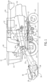
- an agricultural harvester in the form of a combine 10, which generally includes a chassis 12, ground engaging wheels 14 and 16, header 18, feeder housing 20, operator cab 22, threshing and separating system 24, cleaning system 26, grain tank 28, and unloading conveyor 30.
- Front wheels 14 are larger flotation type wheels, and rear wheels 16 are smaller steerable wheels. Motive force is selectively applied to front wheels 14 through a power plant in the form of a diesel engine 32 and a transmission (not shown). Although combine 10 is shown as including wheels, is also to be understood that combine 10 may include tracks.
- Header 18 is mounted to the front of combine 10 and includes a cutter bar 34 for severing crops from a field during forward motion of combine 10.
- a rotatable reel 36 feeds the crop into header 18, and a double auger 38 feeds the severed crop laterally inwardly from each side toward feeder housing 20.
- Feeder housing 20 conveys the cut crop to threshing and separating system 24, and is selectively vertically movable using appropriate actuators, such as hydraulic cylinders (not shown).
- Threshing and separating system 24 generally includes a rotor 40 at least partially enclosed by and rotatable within a corresponding perforated concave 42.
- the cut crops are threshed and separated by the rotation of rotor 40 within concave 42, and larger elements, such as stalks, leaves and the like are discharged from the rear of combine 10.
- Smaller elements of crop material including grain and non-grain crop material, including particles lighter than grain, such as chaff, dust and straw, are discharged through perforations of concave 42.
- Threshing and separating system 24 can also be a different type of system, such as a system with a transverse rotor rather than an axial rotor, etc.
- Cleaning system 26 may include an optional pre-cleaning sieve 46, an upper sieve 48 (also known as a chaffer sieve), a lower sieve 50 (also known as a cleaning sieve), and a cleaning fan 52.
- the upper sieve 48 and lower sieve 50 can be carried within a common framework. Grain on sieves 46, 48 and 50 is subjected to a cleaning action by fan 52 which provides an air flow through the sieves to remove chaff and other impurities such as dust from the grain by making this material airborne for discharge from straw hood 54 of combine 10.
- Grain pan 44 and pre-cleaning sieve 46 oscillate in a fore-to-aft manner to transport the grain and finer non-grain crop material to the upper surface of upper sieve 48.
- Upper sieve 48 and lower sieve 50 are vertically arranged relative to each other, and likewise oscillate in a fore-to-aft manner to spread the grain across sieves 48, 50, while permitting the passage of cleaned grain by gravity through the openings of sieves 48, 50.
- Clean grain falls to a clean grain auger 56 positioned crosswise below and toward the front of lower sieve 50.
- Clean grain auger 56 receives clean grain from each sieve 48, 50 and from bottom pan 58 of cleaning system 26.
- Clean grain auger 56 conveys the clean grain laterally to a generally vertically arranged grain elevator 60 for transport to grain tank 28.
- Tailings from cleaning system 26 fall to a tailings auger trough 62.
- the tailings are transported via tailings auger 64 and return auger 66 to the upstream end of cleaning system 26 for repeated cleaning action.
- a pair of grain tank augers 68 at the bottom of grain tank 28 convey the clean grain laterally within grain tank 28 to unloading conveyor 30 for discharge from combine 10.
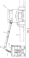
- FIG. 2 is a rear end view of the combine 10 of FIG. 1 showing grain unloading from unloading conveyor 30 of combine 10 into a truck 102.
- Unloading conveyor 30 is shown transversely extending and deployed outwardly in an unloading position as it unloads grain 70 through an unload spout 100 into grain truck 102.
- This unloading operation can occur as combine 10 and truck 102 are moving, which is referred to as unloading "on the go", or the unloading operation can occur in a stationary manner.
- unloading conveyor 30 will be pivoted to a rearwardly directed transport position, extending along the adjacent side of combine 10.
- truck 102 is located a substantial distance to the side of combine 10, which is desired to avoid the possibility of contact with header 18 mounted on the front of combine 10, particularly when unloading on the go. It should also be noted that conveyor 30, when in the unloading position illustrated, will typically be tilted up toward the outer end thereof, at a greater angle, compared to when in the transport position, as additional height is often required to clear the top of the grain receptacle, here illustrated by truck 102.
- FIG. 3 depicts a view of the unloading conveyor 30 of the combine 10 of FIG. 1 , wherein the unload conveyor 30 is shown partially cut-away to reveal an auger 110 of the unloading conveyor 30.
- Auger 110 is positioned and concealed within the interior of a cylindrical outer tube 118 (shown cutaway).
- Unload spout 100 is pivotably mounted to outer tube 118 by a fastener, pin or other pivot device 122, which defines a pivot point 122' for spout 100.
- An actuator 120 is connected to (i) a fixed point (not shown) on either outer tube 118 or another stationary surface, and (ii) a mounting point 124 on spout 100.
- Actuator 120 includes a piston and cylinder arrangement, whereby the piston is configured to extend from the cylinder to pivot spout 100 about pivot point 122'.
- auger 110 rotates to move the clean grain through the tube 118 of conveyor 30 toward unload spout 100.
- actuator 120 is operated to pivot spout 100 to a desired position for discharging clean grain from conveyor 30.
- spout 100 is a pivoting spout, it should be understood that spout 100 may be fixed, non-pivotable and locked in position.
- actuator 120 is an optional component.
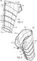
- FIGs. 4-10 provide additional views of unload spout 100.
- spout 100 comprises a hollow body 150 formed from two symmetrical halves 150a and 150b.
- Body 150 includes an open top end 151a (i.e., inlet end) and an open bottom end 151b (i.e., outlet end).
- Halves 150a and 150b are mated together at a front facing flange 154 and a rear facing flange 155. Each flange 154, 155 extends at or near the entire length of body 150 along axis 101.
- Mounting point 124 is disposed on the top end of flange 154.
- a series of fasteners 156 are mounted along the length of each flange 154, 155 to fix the halves 150a and 150b together.
- Mated flanges 154, 155 together form vertical (or substantially vertical) ribs that enhance the stiffness and structural integrity of spout 100.
- Flanges 154, 155 project outwardly from body 150 (i.e., away from the axis 101). The protruding length of flange 154 is greatest at or near mounting point 124.
- a series of openings 159 are disposed through flange 154.
- the top end surface 151a of body 150 includes a front-facing angled portion (or surface) 157 ( FIG. 5 ).
- Portion 157 includes a flange for receiving fasteners such that portion 157 may be mounted to another component.
- Top end surface 151a extends along two different planes that are spaced apart by an obtuse angle Z ( FIG. 8 ). Pivot point 122' is disposed adjacent to the intersection between those two planes.
- the cross-sectional hollow area of body 150 progressively decreases from top end 151a to bottom end 151b.
- the perimeter of top end 151a is greater than that of bottom end 151b.
- Body 150 may be described as having a D-shape as viewed in cross-section (along axis 103).
- the front wall of body 150 (by flange 154) forms an acute angle with longitudinal axis 101
- the rear wall of body by flange 155) forms a larger acute angle with longitudinal axis 101.
- the front wall of body 150 may be vertical or substantially vertical (+/- 5 degrees) and parallel (or nearly parallel) to axis 101.
- the front and rear walls of body 150 each approach axis 101 as viewed in the downward direction toward bottom end surface 151b.
- Bottom end surface 151b also forms an acute angle relative to axis 101.
- top end 151a (not considering angled portion 157) is substantially orthogonal to axis 101.
- Angled portion 157 forms an acute angle with axis 101.
- Steps 160 are formed on the interior surface of the side wall 153 of body 150.
- Steps 160 may also be referred to as fall steps or inverted steps.
- the interior surface of body 150 may be described as stepped, undulating, curved, zig zag, corrugated, wavy, non-planar, or non-smooth, for example.
- the steps 160 like the flanges, enhance the stiffness and structural integrity of spout 100.
- Each step 160 extends about the entire inner perimeter of the body, with the possible exception of the areas at flanges 154, 155.
- the steps 160 are spaced apart along the length dimension (i.e., along axis 101), and may extend from the top end 151a to the bottom end 151b. According to one example, the steps 160 may extend at least 25% of the length dimension, or more preferably at least 50% of the length dimension, or even more preferably at least 75% of the length dimension.
- the steps 160 may be spaced apart along axis 101 either uniformly (as shown) or non-uniformly. As shown in FIG. 3 , each step 160 extends along a plane 105 that is oriented at an acute angle relative to a horizontal axis 103 (the axis 103 being orthogonal to longitudinal axis 101). The steps 160 are also oriented in the same direction relative to axis 103 as outlet end 151b.
Landscapes
- Life Sciences & Earth Sciences (AREA)
- Environmental Sciences (AREA)
- Threshing Machine Elements (AREA)
Abstract
Description
- The present disclosure relates to an unload spout for use with an agricultural vehicle, such as a combine harvester.
- An unload spout of an agricultural vehicle, such as a combine harvester, is used to control the flow of grain out of a tube and into a grain storage or transport container. To maintain control of grain flow, the spout should hold its shape. As the latest clean grain unload systems have increased in capacity, it would be desirable to optimize the rigidity, stiffness and weight of the unload spout in order to maintain the desired clean grain flow characteristics and capacity through the unload spout.
- According to one aspect, an unload spout for an agricultural vehicle includes a hollow body having an inlet end for receiving crop material, an outlet end through which the crop material is distributed, and a side wall extending between the inlet end and the outlet end. A plurality of steps are formed on an interior facing side of the side wall for enhancing the structural integrity of the unload spout.
- The above-mentioned and other features and advantages of this invention, and the manner of attaining them, will become more apparent and the invention will be better understood by reference to the following description of embodiments of the invention taken in conjunction with the accompanying drawings, wherein:
-
FIG. 1 is a side cutaway view of an embodiment of an agricultural harvester in the form of a combine, which is shown schematically. -
FIG. 2 is a rear end view of the combine ofFIG. 1 showing grain unloading from an unloading conveyor of the combine into a truck. -
FIG. 3 depicts a view of an end portion of the unloading conveyor of the combine ofFIG. 1 , wherein the unload conveyor is shown partially cut-away to reveal an auger. -
FIGs. 4-5 depict isometric views of the unload spout of the unloading conveyor ofFIG. 3 . -
FIGs. 6-10 depict front, rear, side, top and bottom views of the unload spout. -
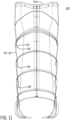
FIG. 11 is a cross-sectional view of the unload spout ofFIG. 8 taken along the lines 11-11. - Corresponding reference characters indicate corresponding parts throughout the several views. The exemplifications set out herein illustrate embodiments of the invention, and such exemplifications are not to be construed as limiting the scope of the invention in any manner.
- The terms "grain", "straw" and "tailings" are used principally throughout this specification for convenience but it is to be understood that these terms are not intended to be limiting. Thus "grain" refers to that part of the crop material which is threshed and separated from the discardable part of the crop material, which is referred to as non-grain crop material, MOG or straw. Incompletely threshed crop material is referred to as "tailings". Also the terms "forward", "rearward", "left" and "right", when used in connection with the agricultural harvester and/or components thereof are usually determined with reference to the direction of forward operative travel of the harvester, but again, they should not be construed as limiting. The terms "longitudinal" and "transverse" are determined with reference to the fore-and-aft direction of the agricultural harvester and are equally not to be construed as limiting.
- Referring now to the drawings, and more particularly to
FIG. 1 , there is shown an agricultural harvester in the form of acombine 10, which generally includes achassis 12, groundengaging wheels header 18,feeder housing 20,operator cab 22, threshing and separatingsystem 24,cleaning system 26,grain tank 28, and unloadingconveyor 30. -
Front wheels 14 are larger flotation type wheels, andrear wheels 16 are smaller steerable wheels. Motive force is selectively applied tofront wheels 14 through a power plant in the form of adiesel engine 32 and a transmission (not shown). Althoughcombine 10 is shown as including wheels, is also to be understood that combine 10 may include tracks. -
Header 18 is mounted to the front ofcombine 10 and includes acutter bar 34 for severing crops from a field during forward motion ofcombine 10. Arotatable reel 36 feeds the crop intoheader 18, and adouble auger 38 feeds the severed crop laterally inwardly from each side towardfeeder housing 20.Feeder housing 20 conveys the cut crop to threshing and separatingsystem 24, and is selectively vertically movable using appropriate actuators, such as hydraulic cylinders (not shown). - Threshing and separating
system 24 generally includes arotor 40 at least partially enclosed by and rotatable within a corresponding perforated concave 42. The cut crops are threshed and separated by the rotation ofrotor 40 within concave 42, and larger elements, such as stalks, leaves and the like are discharged from the rear ofcombine 10. Smaller elements of crop material including grain and non-grain crop material, including particles lighter than grain, such as chaff, dust and straw, are discharged through perforations of concave 42. Threshing and separatingsystem 24 can also be a different type of system, such as a system with a transverse rotor rather than an axial rotor, etc. - Grain which has been separated by the threshing and separating
assembly 24 falls onto agrain pan 44 and is conveyed towardcleaning system 26.Cleaning system 26 may include an optional pre-cleaningsieve 46, an upper sieve 48 (also known as a chaffer sieve), a lower sieve 50 (also known as a cleaning sieve), and acleaning fan 52. Theupper sieve 48 andlower sieve 50 can be carried within a common framework. Grain onsieves fan 52 which provides an air flow through the sieves to remove chaff and other impurities such as dust from the grain by making this material airborne for discharge fromstraw hood 54 of combine 10. Grainpan 44 and pre-cleaningsieve 46 oscillate in a fore-to-aft manner to transport the grain and finer non-grain crop material to the upper surface ofupper sieve 48.Upper sieve 48 andlower sieve 50 are vertically arranged relative to each other, and likewise oscillate in a fore-to-aft manner to spread the grain acrosssieves sieves - Clean grain falls to a
clean grain auger 56 positioned crosswise below and toward the front oflower sieve 50.Clean grain auger 56 receives clean grain from eachsieve bottom pan 58 ofcleaning system 26.Clean grain auger 56 conveys the clean grain laterally to a generally vertically arrangedgrain elevator 60 for transport tograin tank 28. Tailings fromcleaning system 26 fall to atailings auger trough 62. The tailings are transported viatailings auger 64 and return auger 66 to the upstream end ofcleaning system 26 for repeated cleaning action. A pair ofgrain tank augers 68 at the bottom ofgrain tank 28 convey the clean grain laterally withingrain tank 28 to unloadingconveyor 30 for discharge fromcombine 10. -
FIG. 2 is a rear end view of thecombine 10 ofFIG. 1 showing grain unloading from unloadingconveyor 30 of combine 10 into atruck 102. Unloadingconveyor 30 is shown transversely extending and deployed outwardly in an unloading position as it unloadsgrain 70 through anunload spout 100 intograin truck 102. This unloading operation can occur as combine 10 andtruck 102 are moving, which is referred to as unloading "on the go", or the unloading operation can occur in a stationary manner. At the end of the unloading operation, unloadingconveyor 30 will be pivoted to a rearwardly directed transport position, extending along the adjacent side ofcombine 10. It can be noted here, thattruck 102 is located a substantial distance to the side ofcombine 10, which is desired to avoid the possibility of contact withheader 18 mounted on the front ofcombine 10, particularly when unloading on the go. It should also be noted thatconveyor 30, when in the unloading position illustrated, will typically be tilted up toward the outer end thereof, at a greater angle, compared to when in the transport position, as additional height is often required to clear the top of the grain receptacle, here illustrated bytruck 102. -
FIG. 3 depicts a view of theunloading conveyor 30 of thecombine 10 ofFIG. 1 , wherein theunload conveyor 30 is shown partially cut-away to reveal anauger 110 of theunloading conveyor 30. Auger 110 is positioned and concealed within the interior of a cylindrical outer tube 118 (shown cutaway).Unload spout 100 is pivotably mounted toouter tube 118 by a fastener, pin orother pivot device 122, which defines a pivot point 122' forspout 100. Anactuator 120 is connected to (i) a fixed point (not shown) on eitherouter tube 118 or another stationary surface, and (ii) amounting point 124 onspout 100.Actuator 120 includes a piston and cylinder arrangement, whereby the piston is configured to extend from the cylinder to pivotspout 100 about pivot point 122'. - In operation,
auger 110 rotates to move the clean grain through thetube 118 ofconveyor 30 towardunload spout 100. And,actuator 120 is operated topivot spout 100 to a desired position for discharging clean grain fromconveyor 30. Althoughspout 100 is a pivoting spout, it should be understood thatspout 100 may be fixed, non-pivotable and locked in position. Thus,actuator 120 is an optional component. -
FIGs. 4-10 provide additional views ofunload spout 100. Turning now to the finer details ofspout 100,spout 100 comprises a hollow body 150 formed from twosymmetrical halves top end 151a (i.e., inlet end) and an openbottom end 151b (i.e., outlet end).Halves front facing flange 154 and arear facing flange 155. Eachflange axis 101. Mountingpoint 124 is disposed on the top end offlange 154. A series offasteners 156 are mounted along the length of eachflange halves flanges spout 100.Flanges flange 154 is greatest at or near mountingpoint 124. As best shown inFIG. 8 , a series ofopenings 159 are disposed throughflange 154. - The
top end surface 151a of body 150 includes a front-facing angled portion (or surface) 157 (FIG. 5 ).Portion 157 includes a flange for receiving fasteners such thatportion 157 may be mounted to another component.Top end surface 151a extends along two different planes that are spaced apart by an obtuse angle Z (FIG. 8 ). Pivot point 122' is disposed adjacent to the intersection between those two planes. - As best shown in
FIG. 3 , the cross-sectional hollow area of body 150 progressively decreases fromtop end 151a tobottom end 151b. The perimeter oftop end 151a is greater than that ofbottom end 151b. Body 150 may be described as having a D-shape as viewed in cross-section (along axis 103). As seen inFIG. 3 , the front wall of body 150 (by flange 154) forms an acute angle withlongitudinal axis 101, and the rear wall of body (by flange 155) forms a larger acute angle withlongitudinal axis 101. Alternatively, the front wall of body 150 may be vertical or substantially vertical (+/- 5 degrees) and parallel (or nearly parallel) toaxis 101. The front and rear walls of body 150 eachapproach axis 101 as viewed in the downward direction towardbottom end surface 151b.Bottom end surface 151b also forms an acute angle relative toaxis 101. In contrast,top end 151a (not considering angled portion 157) is substantially orthogonal toaxis 101.Angled portion 157 forms an acute angle withaxis 101. - Turning now to
FIGs. 3 and11 , a series ofsteps 160 are formed on the interior surface of theside wall 153 of body 150.Steps 160 may also be referred to as fall steps or inverted steps. The interior surface of body 150 may be described as stepped, undulating, curved, zig zag, corrugated, wavy, non-planar, or non-smooth, for example. Thesteps 160, like the flanges, enhance the stiffness and structural integrity ofspout 100. Eachstep 160 extends about the entire inner perimeter of the body, with the possible exception of the areas atflanges steps 160 are spaced apart along the length dimension (i.e., along axis 101), and may extend from thetop end 151a to thebottom end 151b. According to one example, thesteps 160 may extend at least 25% of the length dimension, or more preferably at least 50% of the length dimension, or even more preferably at least 75% of the length dimension. Thesteps 160 may be spaced apart alongaxis 101 either uniformly (as shown) or non-uniformly. As shown inFIG. 3 , eachstep 160 extends along aplane 105 that is oriented at an acute angle relative to a horizontal axis 103 (theaxis 103 being orthogonal to longitudinal axis 101). Thesteps 160 are also oriented in the same direction relative toaxis 103 asoutlet end 151b. - Each
step 160 includes an elongated lengthwise portion 161 forming theside wall 153, and a horizontally-orientedlanding 162 depending from the lengthwise portion 161. Each landing 162 extends along arespective plane 105. Lengthwise portion 161 faces and forms an acute angle withaxis 101 whereas landing 162 faces thebottom end 151b and forms an acute angle withhorizontal axis 103. Landing 162 is oriented substantially perpendicular to lengthwise portion 161. Due to the effects of gravity, the clean grain does not accumulate on thelandings 162 of the steps. - While this invention has been described with respect to at least one embodiment, the present invention can be further modified within the scope of the appended claims.
Claims (15)
- An unload spout (100) for an agricultural vehicle (10), said unload spout comprising:a hollow body (150) comprising an inlet end (151a) for receiving crop material, an outlet end (151b) through which the crop material is distributed, and a side wall (153) extending between the inlet end (151a) and the outlet end (151b),characterized in that the hollow body (150) further comprises a plurality of steps (160) formed on an interior facing side of the side wall (153).
- The unload spout of claim 1, wherein each step (160) includes a lengthwise portion (161) extending between the inlet and outlet ends (151a, 151b), and a stepped portion (162) depending from the lengthwise portion (161) that faces the outlet end, wherein the stepped portion (162) is inverted such that the crop material is either limited or prevented from accumulating on the stepped portion.
- The unload spout of any one of the foregoing claims, wherein each step (160) includes one of a rounded edge or a sharp edge.
- The unload spout of any one of the foregoing claims, wherein the steps (160) extend more than 50 percent of a length dimension of the hollow body (150).
- The unload spout of any one of the foregoing claims, wherein the steps (160) are spaced apart along a longitudinal axis (101) of the hollow body (150).
- The unload spout of any one of the foregoing claims, wherein a perimeter of the inlet end (151a) is greater than a perimeter of the outlet end (151b), wherein each perimeter is measured along a plane (103) that is normal to a direction of the grain passing through the spout (100).
- The unload spout of any one of the foregoing claims, wherein the hollow body (150) comprises a two-piece body having symmetrical half portions (150a, 150b).
- The unload spout of claim 7, wherein each symmetrical half portion (150a, 150b) includes an outwardly extending flange portion (157), and wherein the outwardly extending flange portions of the flanges are fastened together to form the hollow body.
- The unload spout of claim 8, further comprising a mounting point (124) disposed on the flanges (157) that is configured to be coupled to an actuator (120) for pivoting the unload spout.
- The unload spout of any one of the foregoing claims, wherein the steps (160) are arranged uniformly along a longitudinal axis of the body (150).
- The unload spout of any one of the foregoing claims, wherein each step (160) is defined along a plane (105) that is oriented at an acute angle with respect to a horizontal axis (103), and wherein the horizontal axis (103) is oriented orthogonal to a longitudinal axis (101) of the body.
- An unloading conveyor (30) comprising an outer tube (118), the unload spout (100) of any one of the foregoing claims mounted to an end of the outer tube, and an auger (110) positioned within the outer tube (118) for transporting the crop material toward the inlet end (151a) of the unload spout.
- The unloading conveyor of claim 12, wherein the unload spout (100) is pivotably connected to the outer tube (118).
- An agricultural vehicle (10) comprising the unloading conveyor (30) of claim 12.
- The agricultural vehicle of claim 14, wherein the agricultural vehicle (10) is a combine harvester.
Applications Claiming Priority (1)
| Application Number | Priority Date | Filing Date | Title |
|---|---|---|---|
| US18/221,981 US12477994B2 (en) | 2023-07-14 | 2023-07-14 | Unload spout for agricultural vehicle |
Publications (1)
| Publication Number | Publication Date |
|---|---|
| EP4491007A1 true EP4491007A1 (en) | 2025-01-15 |
Family
ID=91946737
Family Applications (1)
| Application Number | Title | Priority Date | Filing Date |
|---|---|---|---|
| EP24188434.5A Pending EP4491007A1 (en) | 2023-07-14 | 2024-07-12 | Unload spout for agricultural vehicle |
Country Status (2)
| Country | Link |
|---|---|
| US (1) | US12477994B2 (en) |
| EP (1) | EP4491007A1 (en) |
Cited By (1)
| Publication number | Priority date | Publication date | Assignee | Title |
|---|---|---|---|---|
| US20250017146A1 (en) * | 2023-07-14 | 2025-01-16 | Cnh Industrial America Llc | Unload spout for agricultural vehicle |
Families Citing this family (1)
| Publication number | Priority date | Publication date | Assignee | Title |
|---|---|---|---|---|
| USD1103225S1 (en) * | 2023-07-14 | 2025-11-25 | Cnh Industrial America Llc | Unload spout for agricultural vehicle |
Citations (5)
| Publication number | Priority date | Publication date | Assignee | Title |
|---|---|---|---|---|
| CA2261796A1 (en) * | 1998-03-25 | 1999-05-17 | Calmar Industries Ltd. | Combine spout |
| US20060016164A1 (en) * | 2004-04-23 | 2006-01-26 | Ryan Debruycker | Telescoping spout for agricultural harvester |
| US7644816B2 (en) * | 2008-04-30 | 2010-01-12 | Cnh America Llc | Grain saving, directable unloader boot assembly |
| US8366372B2 (en) * | 2009-04-15 | 2013-02-05 | Cnh America Llc | Grain unloading conveyor with directable spout and closure apparatus and system |
| US9604785B1 (en) * | 2016-02-08 | 2017-03-28 | J. & M. Manufacturing Co., Inc. | Telescoping flow control discharge spout assembly for a conveyor of granular material |
Family Cites Families (7)
| Publication number | Priority date | Publication date | Assignee | Title |
|---|---|---|---|---|
| US5546738A (en) * | 1994-11-07 | 1996-08-20 | Turner; Bruce A. | Device for collecting lawn debris |
| JP2004147617A (en) | 2002-11-01 | 2004-05-27 | Yukio Nishizawa | Cover for discharge port of auger, control stick and method for controlling cover for discharge port of auger |
| CA3031910C (en) | 2012-01-09 | 2020-07-21 | Cnh Industrial Canada, Ltd. | Rotary flow divider assembly for agricultural product distribution system |
| US9468145B2 (en) * | 2012-10-19 | 2016-10-18 | Cnh Industrial America Llc | Seal for unloading conveyor arrangement |
| US10390491B2 (en) * | 2017-06-13 | 2019-08-27 | Deere & Company | Cleaning shoe venting through chopper rotor assembly |
| US10806077B2 (en) * | 2017-11-10 | 2020-10-20 | Deere & Company | Agricultural combine with electrostatic grain cleaner |
| US12477994B2 (en) * | 2023-07-14 | 2025-11-25 | Cnh Industrial America Llc | Unload spout for agricultural vehicle |
-
2023
- 2023-07-14 US US18/221,981 patent/US12477994B2/en active Active
-
2024
- 2024-07-12 EP EP24188434.5A patent/EP4491007A1/en active Pending
Patent Citations (5)
| Publication number | Priority date | Publication date | Assignee | Title |
|---|---|---|---|---|
| CA2261796A1 (en) * | 1998-03-25 | 1999-05-17 | Calmar Industries Ltd. | Combine spout |
| US20060016164A1 (en) * | 2004-04-23 | 2006-01-26 | Ryan Debruycker | Telescoping spout for agricultural harvester |
| US7644816B2 (en) * | 2008-04-30 | 2010-01-12 | Cnh America Llc | Grain saving, directable unloader boot assembly |
| US8366372B2 (en) * | 2009-04-15 | 2013-02-05 | Cnh America Llc | Grain unloading conveyor with directable spout and closure apparatus and system |
| US9604785B1 (en) * | 2016-02-08 | 2017-03-28 | J. & M. Manufacturing Co., Inc. | Telescoping flow control discharge spout assembly for a conveyor of granular material |
Cited By (2)
| Publication number | Priority date | Publication date | Assignee | Title |
|---|---|---|---|---|
| US20250017146A1 (en) * | 2023-07-14 | 2025-01-16 | Cnh Industrial America Llc | Unload spout for agricultural vehicle |
| US12477994B2 (en) * | 2023-07-14 | 2025-11-25 | Cnh Industrial America Llc | Unload spout for agricultural vehicle |
Also Published As
| Publication number | Publication date |
|---|---|
| US12477994B2 (en) | 2025-11-25 |
| US20250017146A1 (en) | 2025-01-16 |
Similar Documents
| Publication | Publication Date | Title |
|---|---|---|
| US9992924B2 (en) | Folding mechanism for wide wheat headers | |
| US9807937B2 (en) | Agricultural harvester with improved rotor transition geometry | |
| US11399466B2 (en) | Agricultural vehicle with adjustable rasp bars | |
| US12477994B2 (en) | Unload spout for agricultural vehicle | |
| EP3245860A1 (en) | Cylindrical rotor cage of an agricultural harvester with adjustable vanes | |
| EP2996457B1 (en) | Cover plate for a clean grain auger in a cleaning system of an agricultural harvester | |
| US12484483B2 (en) | Sieve installation arrangement in a cleaning system of an agricultural harvester | |
| US9736982B2 (en) | Grain tank with increased storage capacity for an agricultural harvester | |
| EP3711475B1 (en) | Removable insert for a threshing rotor cage | |
| EP3479675B1 (en) | Rotor cage with flat walls for an agricultural vehicle | |
| EP4512224B1 (en) | Unload tube lock for agricultural vehicle | |
| EP4501098A1 (en) | Unload tube swing cylinder mount for agricultural vehicle | |
| EP3157319B1 (en) | Straw walker arrangement for an agricultural harvester | |
| US12419221B2 (en) | Sieve for an agricultural harvester including extruded sides with polymeric strips | |
| US20250089621A1 (en) | Combine harvester having progressive separator vanes | |
| US20240357969A1 (en) | Unload tube for agricultural vehicle |
Legal Events
| Date | Code | Title | Description |
|---|---|---|---|
| PUAI | Public reference made under article 153(3) epc to a published international application that has entered the european phase |
Free format text: ORIGINAL CODE: 0009012 |
|
| STAA | Information on the status of an ep patent application or granted ep patent |
Free format text: STATUS: THE APPLICATION HAS BEEN PUBLISHED |
|
| AK | Designated contracting states |
Kind code of ref document: A1 Designated state(s): AL AT BE BG CH CY CZ DE DK EE ES FI FR GB GR HR HU IE IS IT LI LT LU LV MC ME MK MT NL NO PL PT RO RS SE SI SK SM TR |
|
| STAA | Information on the status of an ep patent application or granted ep patent |
Free format text: STATUS: REQUEST FOR EXAMINATION WAS MADE |
|
| 17P | Request for examination filed |
Effective date: 20250715 |
|
| STAA | Information on the status of an ep patent application or granted ep patent |
Free format text: STATUS: EXAMINATION IS IN PROGRESS |
|
| 17Q | First examination report despatched |
Effective date: 20251218 |