EP4491005A1 - Vehicle-type traveling apparatus - Google Patents
Vehicle-type traveling apparatus Download PDFInfo
- Publication number
- EP4491005A1 EP4491005A1 EP23899882.7A EP23899882A EP4491005A1 EP 4491005 A1 EP4491005 A1 EP 4491005A1 EP 23899882 A EP23899882 A EP 23899882A EP 4491005 A1 EP4491005 A1 EP 4491005A1
- Authority
- EP
- European Patent Office
- Prior art keywords
- vehicle
- speed
- steering
- driving device
- type driving
- Prior art date
- Legal status (The legal status is an assumption and is not a legal conclusion. Google has not performed a legal analysis and makes no representation as to the accuracy of the status listed.)
- Granted
Links
Images










Classifications
-
- B—PERFORMING OPERATIONS; TRANSPORTING
- B60—VEHICLES IN GENERAL
- B60W—CONJOINT CONTROL OF VEHICLE SUB-UNITS OF DIFFERENT TYPE OR DIFFERENT FUNCTION; CONTROL SYSTEMS SPECIALLY ADAPTED FOR HYBRID VEHICLES; ROAD VEHICLE DRIVE CONTROL SYSTEMS FOR PURPOSES NOT RELATED TO THE CONTROL OF A PARTICULAR SUB-UNIT
- B60W10/00—Conjoint control of vehicle sub-units of different type or different function
- B60W10/20—Conjoint control of vehicle sub-units of different type or different function including control of steering systems
-
- B—PERFORMING OPERATIONS; TRANSPORTING
- B62—LAND VEHICLES FOR TRAVELLING OTHERWISE THAN ON RAILS
- B62D—MOTOR VEHICLES; TRAILERS
- B62D11/00—Steering non-deflectable wheels; Steering endless tracks or the like
- B62D11/001—Steering non-deflectable wheels; Steering endless tracks or the like control systems
- B62D11/003—Electric or electronic control systems
-
- A—HUMAN NECESSITIES
- A01—AGRICULTURE; FORESTRY; ANIMAL HUSBANDRY; HUNTING; TRAPPING; FISHING
- A01D—HARVESTING; MOWING
- A01D34/00—Mowers; Mowing apparatus of harvesters
- A01D34/01—Mowers; Mowing apparatus of harvesters characterised by features relating to the type of cutting apparatus
- A01D34/412—Mowers; Mowing apparatus of harvesters characterised by features relating to the type of cutting apparatus having rotating cutters
- A01D34/63—Mowers; Mowing apparatus of harvesters characterised by features relating to the type of cutting apparatus having rotating cutters having cutters rotating about a vertical axis
-
- A—HUMAN NECESSITIES
- A01—AGRICULTURE; FORESTRY; ANIMAL HUSBANDRY; HUNTING; TRAPPING; FISHING
- A01D—HARVESTING; MOWING
- A01D34/00—Mowers; Mowing apparatus of harvesters
- A01D34/01—Mowers; Mowing apparatus of harvesters characterised by features relating to the type of cutting apparatus
- A01D34/412—Mowers; Mowing apparatus of harvesters characterised by features relating to the type of cutting apparatus having rotating cutters
- A01D34/63—Mowers; Mowing apparatus of harvesters characterised by features relating to the type of cutting apparatus having rotating cutters having cutters rotating about a vertical axis
- A01D34/64—Mowers; Mowing apparatus of harvesters characterised by features relating to the type of cutting apparatus having rotating cutters having cutters rotating about a vertical axis mounted on a vehicle, e.g. a tractor, or drawn by an animal or a vehicle
- A01D34/66—Mowers; Mowing apparatus of harvesters characterised by features relating to the type of cutting apparatus having rotating cutters having cutters rotating about a vertical axis mounted on a vehicle, e.g. a tractor, or drawn by an animal or a vehicle with two or more cutters
-
- B—PERFORMING OPERATIONS; TRANSPORTING
- B60—VEHICLES IN GENERAL
- B60L—PROPULSION OF ELECTRICALLY-PROPELLED VEHICLES; SUPPLYING ELECTRIC POWER FOR AUXILIARY EQUIPMENT OF ELECTRICALLY-PROPELLED VEHICLES; ELECTRODYNAMIC BRAKE SYSTEMS FOR VEHICLES IN GENERAL; MAGNETIC SUSPENSION OR LEVITATION FOR VEHICLES; MONITORING OPERATING VARIABLES OF ELECTRICALLY-PROPELLED VEHICLES; ELECTRIC SAFETY DEVICES FOR ELECTRICALLY-PROPELLED VEHICLES
- B60L15/00—Methods, circuits, or devices for controlling the traction-motor speed of electrically-propelled vehicles
- B60L15/20—Methods, circuits, or devices for controlling the traction-motor speed of electrically-propelled vehicles for control of the vehicle or its driving motor to achieve a desired performance, e.g. speed, torque, programmed variation of speed
- B60L15/2036—Electric differentials, e.g. for supporting steering vehicles
-
- B—PERFORMING OPERATIONS; TRANSPORTING
- B60—VEHICLES IN GENERAL
- B60W—CONJOINT CONTROL OF VEHICLE SUB-UNITS OF DIFFERENT TYPE OR DIFFERENT FUNCTION; CONTROL SYSTEMS SPECIALLY ADAPTED FOR HYBRID VEHICLES; ROAD VEHICLE DRIVE CONTROL SYSTEMS FOR PURPOSES NOT RELATED TO THE CONTROL OF A PARTICULAR SUB-UNIT
- B60W2520/00—Input parameters relating to overall vehicle dynamics
- B60W2520/10—Longitudinal speed
-
- B—PERFORMING OPERATIONS; TRANSPORTING
- B60—VEHICLES IN GENERAL
- B60W—CONJOINT CONTROL OF VEHICLE SUB-UNITS OF DIFFERENT TYPE OR DIFFERENT FUNCTION; CONTROL SYSTEMS SPECIALLY ADAPTED FOR HYBRID VEHICLES; ROAD VEHICLE DRIVE CONTROL SYSTEMS FOR PURPOSES NOT RELATED TO THE CONTROL OF A PARTICULAR SUB-UNIT
- B60W2540/00—Input parameters relating to occupants
- B60W2540/18—Steering angle
-
- B—PERFORMING OPERATIONS; TRANSPORTING
- B62—LAND VEHICLES FOR TRAVELLING OTHERWISE THAN ON RAILS
- B62D—MOTOR VEHICLES; TRAILERS
- B62D1/00—Steering controls, i.e. means for initiating a change of direction of the vehicle
- B62D1/02—Steering controls, i.e. means for initiating a change of direction of the vehicle vehicle-mounted
- B62D1/04—Hand wheels
-
- B—PERFORMING OPERATIONS; TRANSPORTING
- B62—LAND VEHICLES FOR TRAVELLING OTHERWISE THAN ON RAILS
- B62D—MOTOR VEHICLES; TRAILERS
- B62D1/00—Steering controls, i.e. means for initiating a change of direction of the vehicle
- B62D1/02—Steering controls, i.e. means for initiating a change of direction of the vehicle vehicle-mounted
- B62D1/04—Hand wheels
- B62D1/046—Adaptations on rotatable parts of the steering wheel for accommodation of switches
-
- B—PERFORMING OPERATIONS; TRANSPORTING
- B62—LAND VEHICLES FOR TRAVELLING OTHERWISE THAN ON RAILS
- B62D—MOTOR VEHICLES; TRAILERS
- B62D1/00—Steering controls, i.e. means for initiating a change of direction of the vehicle
- B62D1/02—Steering controls, i.e. means for initiating a change of direction of the vehicle vehicle-mounted
- B62D1/16—Steering columns
- B62D1/18—Steering columns yieldable or adjustable, e.g. tiltable
-
- B—PERFORMING OPERATIONS; TRANSPORTING
- B62—LAND VEHICLES FOR TRAVELLING OTHERWISE THAN ON RAILS
- B62D—MOTOR VEHICLES; TRAILERS
- B62D11/00—Steering non-deflectable wheels; Steering endless tracks or the like
- B62D11/02—Steering non-deflectable wheels; Steering endless tracks or the like by differentially driving ground-engaging elements on opposite vehicle sides
- B62D11/04—Steering non-deflectable wheels; Steering endless tracks or the like by differentially driving ground-engaging elements on opposite vehicle sides by means of separate power sources
-
- B—PERFORMING OPERATIONS; TRANSPORTING
- B62—LAND VEHICLES FOR TRAVELLING OTHERWISE THAN ON RAILS
- B62D—MOTOR VEHICLES; TRAILERS
- B62D5/00—Power-assisted or power-driven steering
- B62D5/001—Mechanical components or aspects of steer-by-wire systems, not otherwise provided for in this maingroup
- B62D5/005—Mechanical components or aspects of steer-by-wire systems, not otherwise provided for in this maingroup means for generating torque on steering wheel or input member, e.g. feedback
-
- B—PERFORMING OPERATIONS; TRANSPORTING
- B62—LAND VEHICLES FOR TRAVELLING OTHERWISE THAN ON RAILS
- B62D—MOTOR VEHICLES; TRAILERS
- B62D6/00—Arrangements for automatically controlling steering depending on driving conditions sensed and responded to, e.g. control circuits
- B62D6/002—Arrangements for automatically controlling steering depending on driving conditions sensed and responded to, e.g. control circuits computing target steering angles for front or rear wheels
- B62D6/003—Arrangements for automatically controlling steering depending on driving conditions sensed and responded to, e.g. control circuits computing target steering angles for front or rear wheels in order to control vehicle yaw movement, i.e. around a vertical axis
-
- B—PERFORMING OPERATIONS; TRANSPORTING
- B62—LAND VEHICLES FOR TRAVELLING OTHERWISE THAN ON RAILS
- B62D—MOTOR VEHICLES; TRAILERS
- B62D6/00—Arrangements for automatically controlling steering depending on driving conditions sensed and responded to, e.g. control circuits
- B62D6/02—Arrangements for automatically controlling steering depending on driving conditions sensed and responded to, e.g. control circuits responsive only to vehicle speed
Definitions
- the present application relates to a power device, for example, a vehicle-type driving device.
- the vehicle-type driving device in the related art is widely used in the fields of trimming lawns, vegetation, and the like. Compared with a push device, the vehicle-type driving device is more labor-saving and more efficient.
- the vehicle-type driving device is required to be able to turn flexibly to satisfy the working requirement.
- a steering wheel is operated in a manner similar to a manner in which a car is driven. Therefore, the vehicle-type driving device whose traveling direction is controlled by the steering wheel is easy to use and very friendly to a novice user.
- the vehicle-type driving device usually decelerates during turning.
- the processing method in which the vehicle-type driving device decelerates during turning results in poor steering feel when the driver drives the vehicle-type driving device to turn and affects the operating experience of the user.
- An object of the present application is to solve or at least alleviate part or all of the preceding problems.
- the present application provides a vehicle-type driving device so that the problem of poor steering feel for a driver driving and turning can be solved, and the operating experience of the user can be improved.
- a vehicle-type driving device includes a traveling assembly including multiple traveling wheels; a steering wheel configured to control the vehicle-type driving device to steer; a traveling motor for driving the vehicle-type driving device to steer at a target angular velocity, where the ratio of the target angular velocity to the change in the steering angle of the steering wheel is defined as a steering ratio; and a control device configured to, when the traveling speed of the vehicle-type driving device is within a preset range, set the steering ratio according to a steering ratio curve function, where variables of the steering ratio curve function include the steering angle of the steering wheel and the traveling speed of the vehicle-type driving device.
- the steering ratio curve function includes a low-speed steering ratio curve function and a high-speed steering ratio curve function
- the preset range includes a low-speed driving threshold and a high-speed driving threshold, where when the traveling speed is less than the low-speed driving threshold, a low-speed steering ratio is set according to the low-speed steering ratio curve function; and when the traveling speed is greater than the high-speed driving threshold, a high-speed steering ratio of a traveling wheel of the multiple traveling wheels is set according to the high-speed steering ratio curve function.
- the multiple traveling wheels include a left traveling wheel and a right traveling wheel
- the low-speed steering ratio curve function includes a left-wheel low-speed steering ratio curve function and a right-wheel low-speed steering ratio curve function, where when the traveling speed of the left traveling wheel is less than the low-speed driving threshold, a low-speed steering ratio of the left traveling wheel is set according to the left-wheel low-speed steering ratio curve function; and when the traveling speed of the right traveling wheel is less than the low-speed driving threshold, a low-speed steering ratio of the right traveling wheel is set according to the right-wheel low-speed steering ratio curve function.
- the multiple traveling wheels include a left traveling wheel and a right traveling wheel
- the high-speed steering ratio curve function includes a left-wheel high-speed steering ratio curve function and a right-wheel high-speed steering ratio curve function, where when the traveling speed of the left traveling wheel is greater than the high-speed driving threshold, a high-speed steering ratio of the left traveling wheel is set according to the left-wheel high-speed steering ratio curve function; and when the traveling speed of the right traveling wheel is greater than the high-speed driving threshold, a high-speed steering ratio of the right traveling wheel is set according to the right-wheel high-speed steering ratio curve function.
- the maximum traveling speed of the vehicle-type driving device is greater than or equal to 11 km/h and less than or equal to 14 km/h, and the low-speed driving threshold is 20% of the maximum traveling speed.
- the maximum traveling speed of the vehicle-type driving device is greater than or equal to 11 km/h and less than or equal to 14 km/h, and the high-speed driving threshold is 90% of the maximum traveling speed.
- the traveling speed of the vehicle-type driving device when the traveling speed of the vehicle-type driving device is between the low-speed driving threshold and the high-speed driving threshold, the low-speed steering ratio in the low-speed steering ratio curve function and the high-speed steering ratio in the high-speed steering ratio curve function are determined according to the steering angle of the steering wheel, and the steering ratio curve function at the traveling speed is determined according to the low-speed steering ratio and the high-speed steering ratio.
- ratio (A_Speed - TH_L)/(TH_H - TH_L), where A_Speed denotes the traveling speed of the vehicle-type driving device, TH_L denotes the low-speed driving threshold, and TH_H denotes the high-speed driving threshold.
- the steering ratio is set according to the steering ratio curve function corresponding to when the traveling speed is between the low-speed driving threshold and the high-speed driving threshold, the target angular velocity is determined according to the steering ratio and the change in the steering angle of the steering wheel, and the traveling speed is determined according to the target angular velocity.
- the vehicle-type driving device further includes a speed setting device for setting the traveling speed of the vehicle-type driving device, where the traveling speed set by the speed setting device is defined as an input speed, the traveling motor drives the vehicle-type driving device to travel at a target speed, the ratio of the target speed to the input speed is defined as a conversion ratio, and the control device is configured to be capable of setting the conversion ratio according to the steering angle of the steering wheel.
- the control device sets the conversion ratio to a first steering conversion ratio; and when the steering wheel has a second steering angle, the control device sets the conversion ratio to a second steering conversion ratio, where the second steering conversion ratio is different from the first steering conversion ratio.
- the vehicle-type driving device further includes a cutting motor, a first energy storage device, a detection device, and the control device, where the cutting motor is configured to drive a cutting assembly to work, the first energy storage device is configured to supply power to the traveling motor and the cutting motor and has a low power state, the detection device is configured to detect whether the first energy storage device is in the low power state, and the control device is configured to control the output states of the traveling motor and the cutting motor.
- the control device when the first energy storage device is in the low power state, the control device reduces the torque of the traveling motor and reduces the maximum rotational acceleration of the traveling motor.
- the vehicle-type driving device further includes a cutting motor configured to drive a cutting assembly to work, a detection device for detecting a first operating parameter and a second operating parameter of the cutting motor, and the control device, where when the first operating parameter is within a first threshold range, the second operating parameter is within a second threshold range, and the duration that the first operating parameter is within the first threshold range and the second operating parameter is within the second threshold range is a first preset time, the control device controls the cutting motor to stop or slow down, the second operating parameter is different from the first operating parameter, and the second operating parameter includes at least the rotational speed of the cutting motor.
- a vehicle-type driving device includes a traveling assembly including multiple traveling wheels; a steering wheel configured to control the vehicle-type driving device to steer; a traveling motor for driving the vehicle-type driving device to steer at a target angular velocity, where the ratio of the target angular velocity to the change in the steering angle of the steering wheel is defined as a steering ratio; and a control device configured to, when the traveling speed of the vehicle-type driving device is within a preset range, set the steering ratio according to a steering ratio curve function, where a variable of the steering ratio curve function includes the traveling speed of the vehicle-type driving device.
- a vehicle-type driving device includes a traveling assembly including multiple traveling wheels; a steering wheel configured to control the vehicle-type driving device to steer; a traveling motor for driving the vehicle-type driving device to steer at a target angular velocity, where the ratio of the target angular velocity to the change in the steering angle of the steering wheel is defined as a steering ratio; and a control device configured to, when the traveling speed of the vehicle-type driving device is within a preset range, set the steering ratio according to multiple steering ratio curve functions, where a variable of at least one of the multiple steering ratio curve functions includes the traveling speed of the vehicle-type driving device.
- the multiple steering ratio curve function include a low-speed steering ratio curve function and a high-speed steering ratio curve function
- the preset range includes a low-speed driving threshold and a high-speed driving threshold, where when the traveling speed is less than the low-speed driving threshold, a low-speed steering ratio is set according to the low-speed steering ratio curve function; and when the traveling speed is greater than the high-speed driving threshold, a high-speed steering ratio of a traveling wheel of the multiple traveling wheels is set according to the high-speed steering ratio curve function.
- the traveling speed of the vehicle-type driving device when the traveling speed of the vehicle-type driving device is between the low-speed driving threshold and the high-speed driving threshold, the low-speed steering ratio in the low-speed steering ratio curve function and the high-speed steering ratio in the high-speed steering ratio curve function are determined according to the steering angle of the steering wheel, and the steering ratio curve function at the traveling speed is determined according to the low-speed steering ratio and the high-speed steering ratio.
- variable of a steering ratio curve function of the multiple steering ratio curve functions includes a steering ratio coefficient of the steering wheel depending on the traveling speed of the vehicle-type driving device, and a value of the steering ratio coefficient of the steering wheel is greater than or equal to 0 and less than or equal to 1.
- a vehicle-type driving device includes a body including a traveling assembly and a traveling motor for driving the traveling assembly; a steering wheel assembly; and a connection assembly connecting the steering wheel assembly to the body.
- the steering wheel assembly includes a steering wheel rotatable about a first axis relative to the connection assembly; a switch electrically connected to the traveling motor to control the traveling motor; an operating member including a trigger portion capable of triggering the switch, where the operating member is rotatably connected to the steering wheel with a second axis as an axis; and a reset element driving the operating member to reset, where the operating member includes a reset portion in contact with the reset element.
- the reset portion and the trigger portion are disposed on two sides of the second axis.
- the reset portion and the trigger portion are disposed on two sides of a plane passing through the second axis and parallel to the first axis.
- the steering wheel assembly includes a steering wheel housing, a main limiting portion is disposed on the steering wheel housing, the main limiting portion is disposed on a side of the second axis facing the trigger portion, and the main limiting portion is configured to limit the displacement of the trigger portion when the trigger portion triggers the switch.
- the main limiting portion includes a first limiting block and a second limiting block
- the operating member is provided with a first limiting portion matching and limiting the first limiting block and a second limiting portion matching and limiting the second limiting block.
- an auxiliary limiting portion is disposed on the steering wheel housing, the auxiliary limiting portion is disposed on a side of the second axis facing the reset portion, and the auxiliary limiting portion is configured to limit the displacement of the trigger portion when the trigger portion triggers the switch.
- At least two reset elements are provided.
- the trigger portion is a trapezoidal structure
- the trigger portion is provided with a trigger surface for triggering the switch
- a reinforced structure is disposed on a side of the trigger portion opposite to the trigger surface.
- the switch is a micro rocker switch.
- a spacer is disposed between the switch and the trigger portion of the operating member, and the spacer is elastic deformable.
- the operating member includes a toggle and a trigger
- the trigger is rotatably connected to the steering wheel housing with the second axis as an axis
- an end of the toggle is detachably connected to the trigger
- the other end of the toggle is disposed on an outer side of the steering wheel housing.
- a vehicle-type driving device includes a traveling assembly including multiple traveling wheels; a traveling motor configured to drive the traveling assembly; a first energy storage device configured to supply power to at least the traveling motor so that the traveling motor drives the traveling assembly to operate; and a second energy storage device configured to, when the power of the first energy storage device is less than a preset value and/or when an electrical energy transmission path from the first energy storage device to the traveling motor fails or is cut off, serve as an electric power source to control the traveling motor to enter a parking mode.
- a controller unit and a drive control unit are further included, and the controller unit is capable of controlling the drive control unit so that the traveling motor drives the traveling assembly to operate.
- the first energy storage device when the power of the first energy storage device is greater than or equal to the preset value, serves as an electric power source so that the drive control unit controls the traveling motor to enter the parking mode.
- the second energy storage device serves as the electric power source so that the drive control unit controls the traveling motor to enter the parking mode.
- the second energy storage device includes a capacitive power supply, where when the power of the first energy storage device is greater than the preset value, the first energy storage device is capable of charging the capacitive power supply; and when the power of the first energy storage device is less than the preset value, the capacitive power supply serves as an electric power source so that the drive control unit controls the traveling motor to enter the parking mode.
- the second energy storage device further includes a first energy storage assembly, where when the traveling assembly coasts, the back electromotive force generated by the traveling motor charges the first energy storage assembly, and the first energy storage assembly charges the capacitive power supply when the power of the capacitive power supply is less than a preset power value.
- the second energy storage device includes a second energy storage assembly, where when the power of the first energy storage device is less than the preset value, the second energy storage assembly serves as an electric power source so that the drive control unit controls the traveling motor to enter the parking mode.
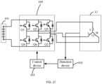
- the drive control unit includes a switching element, and the switching element is powered and triggered to control the traveling motor to enter the parking mode.
- three phases of the traveling motor are short-circuited so that the traveling motor enters the parking mode.
- the parking mode is a mode in which the traveling motor slows down or stops.
- a vehicle-type driving device includes a cutting assembly including a mowing element for mowing grass; a chassis supporting the cutting assembly; a cutting motor configured to drive the cutting assembly; a detection device for detecting a first operating parameter and a second operating parameter of the cutting motor; and a control device for controlling the cutting motor to stop or slow down when the first operating parameter is within a first threshold range, the second operating parameter is within a second threshold range, and the duration that the first operating parameter is within the first threshold range and the second operating parameter is within the second threshold range is a first preset time.
- the second operating parameter is different from the first operating parameter, and the second operating parameter includes at least the rotational speed of the cutting motor.
- control device controls the cutting motor to stop in a second preset time.
- the second preset time is greater than 1s.
- the first operating parameter includes the bus current or the phase current.
- the first operating parameter includes the bus current, and the first threshold range is greater than 0 A and less than or equal to 3 A.
- the first operating parameter includes the phase current
- the first threshold range is greater than 0 A and less than or equal to 4 A.
- the second operating parameter includes the actual rotational speed and the target rotational speed of an electric motor
- the second threshold range includes an actual rotational speed range and a target rotational speed range of the electric motor, where when the actual rotational speed of the electric motor is within the actual rotational speed range of the electric motor for the first preset time and the target rotational speed of the electric motor is within the target rotational speed range of the electric motor for the first preset time, the control device controls the cutting motor to stop or slow down.
- the actual rotational speed range of the electric motor is greater than or equal to 500 r/min, and the target rotational speed range of the electric motor is greater than or equal to 1950 r/min.
- the vehicle-type driving device further includes a traveling assembly, a traveling motor for driving the traveling assembly to operate, a display screen, a switch panel, and a battery management system, where before the control device controls the cutting motor to start, whether the traveling motor, the display screen, the switch panel, and the battery management system communicate normally with the control device separately is determined; and if so, the cutting motor starts.
- the cutting motor stops.
- a vehicle-type driving device includes a traveling assembly including multiple traveling wheels; a steering wheel configured to control the vehicle-type driving device to steer; a speed setting device for setting the traveling speed of the vehicle-type driving device, where the traveling speed set by the speed setting device is defined as the input speed; a traveling motor for driving the vehicle-type driving device to travel at the target speed, where the ratio of the target speed to the input speed is defined as a conversion ratio; and a control device configured to set the conversion ratio according to a steering angle of the steering wheel.
- the control device sets the conversion ratio to a first steering conversion ratio; and when the steering wheel has a second steering angle, the control device sets the conversion ratio to a second steering conversion ratio, where the second steering conversion ratio is different from the first steering conversion ratio.
- the steering process of the vehicle-type driving device includes a first steering stage and a second steering stage, where the steering angle in the first steering stage is the first steering angle, the steering angle in the second steering stage is the second steering angle, the first steering conversion ratio remains unchanged when the vehicle-type driving device is in the first steering stage, and the second steering conversion ratio changes linearly when the vehicle-type driving device is in the second steering stage.
- the first steering conversion ratio is 100%.
- the steering wheel is capable of controlling the vehicle-type driving device to straighten out, and a direction in which the vehicle-type driving device straightens out is opposite to a direction in which the vehicle-type driving device steers.
- the minimum speed of the vehicle-type driving device during the steering process is acquired, where the minimum speed is the initial target speed of the vehicle-type driving device during a straightening-out process.
- the control device sets the conversion ratio to a first straightening-out conversion ratio; and when the steering wheel has a second straightening-out angle, the control device sets the conversion ratio to a second straightening-out conversion ratio, where the second straightening-out conversion ratio is different from the first straightening-out conversion ratio.
- the straightening-out process of the vehicle-type driving device includes a first straightening-out stage and a second straightening-out stage, where a straightening-out angle in the first straightening-out stage is the first straightening-out angle, a straightening-out angle in the second straightening-out stage is the second straightening-out angle, the first straightening-out conversion ratio remains unchanged when the vehicle-type driving device is in the first straightening-out stage, and the second straightening-out conversion ratio changes linearly when the vehicle-type driving device is in the second straightening-out stage.
- the first straightening-out conversion ratio is 30%.
- the second straightening-out conversion ratio changes from 30% to 100% within a preset time.
- a vehicle-type driving device includes a traveling assembly including traveling wheels; a traveling motor configured to drive the traveling assembly; a cutting motor configured to drive a cutting assembly to operate; a first energy storage device configured to supply power to the traveling motor and the cutting motor, where the first energy storage device has a low power state; a detection device configured to detect whether the first energy storage device is in the low power state; and a control device configured to control the output states of the traveling motor and the cutting motor.
- the control device reduces the torque of the traveling motor and reduces the maximum rotational acceleration of the traveling motor.
- the detection device detects whether the first energy storage device is in the low power state by detecting the voltage or the remaining power of the first energy storage device, where when the voltage or the remaining power of the first energy storage device is lower than or equal to a first preset level, the first energy storage device is in the low power state.
- the control device when the first energy storage device is in the low power state, the control device reduces the maximum rotational speed of the traveling motor.
- the control device when the first energy storage device is in the low power state, the control device reduces the torque of the cutting motor.
- the maximum rotational speed of the cutting motor remains unchanged compared to the preset maximum rotational speed of the cutting motor
- the maximum rotational acceleration of the cutting motor remains unchanged compared to the preset maximum rotational acceleration of the cutting motor
- the first energy storage device when the voltage or the remaining power of the first energy storage device is lower than or equal to a second preset level lower than the first preset level, the first energy storage device is in a deep low power state, and the control device disables the power output of the traveling motor and the cutting motor.
- the first energy storage device in the low power state, when the voltage or the remaining power of the first energy storage device increases to be higher than the first preset level, the first energy storage device exits the low power state.
- the control device increases the torque of the traveling motor and increases the maximum rotational acceleration of the traveling motor.
- the control device when the first energy storage device is in the low power state, the control device reduces the maximum rotational speed of the traveling motor and the torque of the cutting motor; and after the first energy storage device exits the low power state, the control device increases the maximum rotational speed of the traveling motor and the torque of the cutting motor.
- the vehicle-type driving device is a riding mower.
- the present application has the beneficial effects below.
- the present application provides the vehicle-type driving device.
- the steering ratio is the ratio of the target angular velocity to the change in the steering angle of the steering wheel.
- the steering ratio is set according to the steering ratio curve function when the traveling speed is within the preset range, and then the traveling speed of the vehicle-type driving device is determined according to the steering ratio and the steering angle of the steering wheel.
- the vehicle-type driving device travels at the traveling speed. In this manner, the traveling speed of the vehicle-type driving device is adjusted according to the steering angle of the steering wheel so that the steering feel of the vehicle-type driving device at different speeds can be improved, the problem of poor operating feel for a driver driving and turning can be solved, and the operating experience of the user can be improved.
- the term "and/or” is a kind of association relationship describing the relationship between associated objects, which means that there can be three kinds of relationships.
- a and/or B can indicate that A exists alone, A and B exist simultaneously, and B exists alone.
- the character "/" in this application generally indicates that the contextual associated objects belong to an "and/or” relationship.
- connection may be direct connection, combination, coupling or installation, and may also be indirect connection, combination, coupling or installation.
- direct connection means that two members or assemblies are connected together without intermediaries
- indirect connection means that two members or assemblies are respectively connected with at least one intermediate members and the two members or assemblies are connected by the at least one intermediate members.
- connection and “coupling” are not limited to physical or mechanical connections or couplings, and may include electrical connections or couplings.
- a relative term (such as “about”, “approximately”, and “substantially) used in conjunction with quantity or condition includes a stated value and has a meaning dictated by the context.
- the relative term includes at least a degree of error associated with the measurement of a particular value, a tolerance caused by manufacturing, assembly, and use associated with the particular value, and the like.
- Such relative term should also be considered as disclosing the range defined by the absolute values of the two endpoints.
- the relative term may refer to plus or minus of a certain percentage (such as 1%, 5%, 10%, or more) of an indicated value. A value that did not use the relative term should also be disclosed as a particular value with a tolerance.
- “substantially” when expressing a relative angular position relationship may refer to adding or subtracting a certain degree (such as 1 degree, 5 degrees, 10 degrees or more) to the indicated angle.
- a function performed by an assembly may be performed by one assembly, multiple assemblies, one member, or multiple members.
- a function performed by a member may be performed by one member, an assembly, or a combination of members.
- controller In this application, the terms “controller”, “processor”, “central processor”, “CPU” and “MCU” are interchangeable. Where a unit “controller”, “processor”, “central processing”, “CPU”, or “MCU” is used to perform a specific function, the specific function may be implemented by a single aforementioned unit or a plurality of the aforementioned unit.
- the term "device”, “module” or “unit” may be implemented in the form of hardware or software to achieve specific functions.
- the terms “computing”, “judging”, “controlling”, “determining”, “recognizing” and the like refer to the operations and processes of a computer system or similar electronic computing device (e.g., controller, processor, etc.).
- this example discloses a vehicle-type driving device 100, specifically, a riding mower. A user can sit on and operate the vehicle-type driving device 100 to trim lawns and other vegetation.
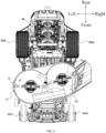
- directions such as the front, rear, left, right, up, and down are described as directions shown in FIG. 1 .
- the direction which the user faces is front
- the direction which the user faces away from is rear
- the direction on the left-hand side of the user is left
- the direction on the right-hand side of the user is right
- the direction towards the ground is down
- the direction away from the ground is up.
- the vehicle-type driving device 100 includes a body 100a, and the body 100a includes a cutting assembly 10, a chassis 91, a seat 92, a housing system 20, a traveling assembly 93, a traveling motor for driving the traveling assembly 93, a power supply assembly 96, an illumination system 40, and an operating assembly 50.
- the chassis 91 and the housing system 20 form the frame structure of the body 100a of the vehicle-type driving device 100, the frame structure of the body 100a is used for mounting the cutting assembly 10, the seat 92, the power supply assembly 96, and the illumination system 40, and the traveling assembly 93 is used for supporting the frame structure of the body 100a.
- the vehicle-type driving device 100 supplies energy to the cutting assembly 10, the traveling assembly 93, the illumination system 40, and the like through a power assembly.
- the power assembly of the vehicle-type driving device 100 is the power supply assembly 96, and the power supply assembly 96 supplies electrical energy to assemblies of the vehicle-type driving device 100 so that the vehicle-type driving device 100 can be used as a power tool.
- the electric vehicle-type driving device 100 is more environmentally friendly and more energy-efficient than a fuel-based vehicle-type driving device 100.
- the cutting assembly 10 is used for outputting power to implement the function of the vehicle-type driving device 100.
- the cutting assembly 10 serves as a power output member, and the body 100a supports the power output member.
- the cutting assembly 10 includes a cutting deck 11, mowing elements 12, and cutting motors 13 for driving the mowing elements 12.
- the power of the cutting motor 13 is about 1500 W.
- the power of the cutting motor 13 is about 3000 W.
- the mowing element 12 is driven by the cutting motor 13 to rotate at a high speed to cut the vegetation.
- the mowing element 12 is a blade for cutting grass on a lawn.
- the cutting deck 11 surrounds a mowing space 121 for accommodating at least part of the mowing element 12, that is to say, the mowing element 12 is at least partially accommodated in the cutting deck 11.
- the cutting motor 13 is used for driving the mowing element 12 to rotate.
- the cutting assembly 10 is disposed below the chassis 91.
- two mowing elements 12 may be provided, two cutting motors 13 may be provided, and correspondingly, the two cutting motors 13 drive the two mowing elements 12, respectively.
- three mowing elements 12 may be provided, three cutting motors 13 may be provided, and correspondingly, the three cutting motors 13 drive the three mowing elements 12, respectively.
- the mowing element 12 is disposed in the mowing space 121 surrounded by the cutting deck 11.
- the mowing space 121 is open downward so that the mowing elements 12 can perform cutting operations on the vegetation below the mowing space 121.
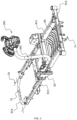
- the chassis 91 basically extends along the front and rear direction of the vehicle-type driving device 100; the cutting assembly 10, the housing system 20, the seat 92, the traveling assembly 93, the power supply assembly 96, and the illumination system 40 are all mounted on the chassis 91; and the chassis 91 is used for supporting the body of the entire vehicle-type driving device 100.
- the traveling assembly 93 is used for supporting the chassis 91 so that the vehicle-type driving device 100 can travel on the ground, and the traveling assembly 93 includes a first traveling assembly 931 and a second traveling assembly 932.
- the first traveling assembly 931 is a front traveling assembly and includes two first traveling wheels, that is, a first left traveling wheel 931L and a first right traveling wheel 931R.
- the second traveling assembly 932 is a rear traveling assembly and includes two second traveling wheels, that is, a second left traveling wheel 932L and a second right traveling wheel 932R.
- the radius of the second traveling wheels is greater than the radius of the first traveling wheels.
- the first left traveling wheel 931L and the first right traveling wheel 931R are connected via a front axle 934.
- the second left traveling wheel 932L and the second right traveling wheel 932R are connected via a rear axle.
- the traveling assembly 93 further includes the traveling motor for driving the second traveling assembly 932.
- two traveling motors are provided, that is to say, each of the second left traveling wheel 932L and the second right traveling wheel 932R is independently driven by a respective traveling motor.
- the power of the traveling motor is about 1500 W. In some examples, the power of the traveling motor is about 3000 W
- the chassis 91 includes rails and beams.
- the chassis 91 includes two rails which are a first rail 911 and a second rail 912, respectively.
- the chassis 91 further includes two beams which are a first beam 913 and a second beam 914, respectively.
- the first rail 911 is disposed on the left side of the seat 92
- the second rail 912 is disposed on the right side of the seat 92.
- the first rail 911 extends along a first straight line 1b
- the second rail 912 extends along a second straight line 1c, where the first straight line 1b and the second straight line 1c are parallel to each other.
- the first rail 911 and the second rail 912 extend along the front and rear direction of the vehicle-type driving device 100, where the extension directions of the first rail 911 and the second rail 912 are parallel to each other.
- the first beam 913 is located basically at the front end of the vehicle-type driving device 100. In this manner, the first beam 913 also serves as a front bumper for protecting the front end of the vehicle-type driving device 100 from being damaged.
- the second beam 914 is located basically at the rear end of the vehicle-type driving device 100. In this manner, the second beam 914 also serves as a rear bumper for protecting the rear end of the vehicle-type driving device 100 from being damaged.
- the first beam 913 and the second beam 914 at least partially extend along a transverse straight line 1e, where the transverse straight line 1e extends along the left and right direction of the vehicle-type driving device 100.
- the extension directions of the first beam 913 and the second beam 914 are parallel to each other, while the transverse straight line 1e is perpendicular to the first straight line 1b and the second straight line 1c.
- the first rail 911, the second rail 912, the first beam 913, and the second beam 914 may be fixed together through fasteners such as bolts or may be fixed together through welding.
- the housing system 20 includes a left cover 21 and a right cover 22.
- the left cover 21 is disposed on the left side of the seat 92
- the right cover 22 is disposed on the right side of the seat 92.
- the left cover 21 at least partially covers the second left traveling wheel 932L
- the right cover 22 at least partially covers the second right traveling wheel 932R.
- the specific structures and materials of the left cover 21 and the right cover 22 are not limited in the present application.
- the housing system 20 further includes a base plate 94 sandwiched between the first rail 911 and the second rail 912 so that when sitting on the vehicle-type driving device 100, the user may step on the base plate 94.
- the power supply assembly 96 is used for supplying electric power to the cutting assembly 10, the traveling assembly 93, the illumination system 40, and the like, where the cutting motor 13, the traveling motor, and the illumination system 40, as electrical devices included in the vehicle-type driving device 100, can convert the electrical energy into other forms of power.
- the power supply assembly 96 includes at least one battery pack for storing the electrical energy. In some examples, the voltage of the battery pack is about 56 V. In some examples, the power supply assembly 96 is disposed at the rear of the vehicle-type driving device 100. The power supply assembly 96 may be disposed behind the seat 92. In other examples, the power supply assembly 96 may be disposed at the front of the vehicle-type driving device 100. In some examples, the power supply assembly 96 includes six battery packs.
- the six battery packs are arranged in three rows along the front and rear direction, and two battery packs are arranged along the left and right direction in each row.
- the power supply assembly 96 may be configured to be a combination of a built-in cell module and an external battery pack.
- the built-in cell module has less cost and a more compact structure than the detachable external battery pack, thereby providing more adequate energy storage for the vehicle-type driving device 100 while saving space and cost.
- a certain number of detachable external battery packs are provided so that the flexibility of the power supply assembly 96 is ensured.
- the user may take only the battery packs away for charging and does not need to drive the entire vehicle-type driving device 100 to a charging station; when the user is inconvenient or has no time to charge the built-in cell module of the vehicle-type driving device 100, the external battery packs are inserted so that the short-time mowing requirement can be satisfied.
- the operating assembly 50 includes a steering wheel assembly 56.
- the steering wheel assembly 56 includes a steering wheel 561 operable by the user to rotate and a support rod 562 configured to connect the steering wheel 561 to the chassis 91.
- the support rod 562 has a first end 5621 connected to the steering wheel 561 and a second end 5622 connected to the chassis 91.
- the support rod 562 is configured to be a hollow tube so that while the cost is saved, the wires of the steering wheel assembly 56 are allowed to pass through the hollow tube, thereby improving the safety and aesthetics of the wiring.
- the steering wheel assembly 56 is mounted to the chassis 91 through a connection assembly 70.
- the support rod 562 is mounted to the rail of the chassis 91 through the connection assembly 70. In some examples, the support rod 562 is mounted to the second rail 912 on the right side of the seat 92 through the connection assembly 70, which is convenient for the user to get on and off from the left side of the vehicle-type driving device 100. In other examples, the support rod 562 may be mounted to the first rail 911 on the left side of the seat 92 through the connection assembly 70. Referring to FIGS.
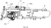
- the connection assembly 70 includes a locked position and an unlocked position, where when the connection assembly 70 is at the unlocked position, the steering wheel 561 and the support rod 562 can slide back and forth relative to the seat 92 so that the steering wheel assembly 56 is switchable between at least a first working position and a second working position.
- the first working position and the second working position are arranged along the front and rear direction of the vehicle-type driving device 100. The first working position is shown in FIG. 4A , and the second working position is shown in FIG. 4B .
- the steering wheel assembly 56 may have more working positions.
- the support rod 562 includes the first end 5621 and the second end 5622, the first end 5621 is fixedly connected to the steering wheel, and the second end 5622 is connected to the connection assembly 70 so that the support rod 562 is mounted to the second rail 912.
- the connection assembly 70 is at the unlocked position, the second end 5622 is slidable along the extension direction of the rail.
- the first end 5621 is a straight tube
- the second end 5622 is also a straight tube
- the first end 5621 and the second end 5622 are connected to each other through an intermediate portion 5623.
- the intermediate portion 5623 is also a straight tube, the first end 5621 and the intermediate portion 5623 are connected to each other through a first bent portion 5624, and the second end 5622 and the intermediate portion 5623 are connected to each other through a second bent portion 5625.
- the first end 5621, the first bent portion 5624, the intermediate portion 5623, the second bent portion 5625, and the second end 5622 described above are used only for identifying different portions of the support rod 562 and do not indicate that these portions are formed by separate or differentiated components.
- first end 5621, the first bent portion 5624, the intermediate portion 5623, the second bent portion 5625, and the second end 5622 may be integrally formed into a whole or may be multiple different components fixed together through the welding, threaded connections, fastener connections, or the like.
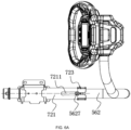
- the connection assembly 70 includes a bracket assembly 71 and a bushing assembly 72, where the bushing assembly 72 is sleeved on the circumference of the second end 5622, and the bracket assembly 71 is fixed on the rail and supports the bushing assembly 72 and the support rod 562.
- the bracket assembly 71 is covered by the right cover 22.
- the bracket assembly 71 includes a substrate 711 and a bracket 712, where the substrate 711 is fixedly mounted to the second rail 912, the bracket 712 is fixed on the substrate 711, an open channel is formed in the extension direction of the second rail 912, and the second end 5622 of the support rod 562 and the bushing assembly 72 pass through the channel and are set up on the bracket 712.
- the substrate 711 is fixed to the second rail 912 through fasteners such as screws or bolts.
- the width of the substrate 711 is greater than the width of the second rail 912.
- edges protruding downward are formed around the substrate 711, and the edges form a groove with a width basically the same as the width of the second rail 912. In this manner, the edges of the substrate 711 are clamped on the second rail 912, thereby preventing the substrate 711 from wobbling or overturning.
- the bracket 712 is fixed to the substrate 711 through fasteners such as bolts and nuts, and the second end 5622 of the support rod 562 and the bushing assembly 72 pass through the bracket 712.
- the bushing assembly 72 is fixed to the bracket 712.
- the second end 5622 of the support rod 562 and the bushing assembly 72 are set up slightly above the second rail 912 or suspended from the second rail 912 by the bracket 712.
- the bushing assembly 72 includes an outer tube 721, a bushing 722, and a hoop 723.
- the outer tube 721 is a hollow tube and extends along the extension direction of the second rail 912.
- an end of the outer tube 721 toward the front of the vehicle-type driving device 100 is defined as a front end
- an end of the outer tube 721 toward the rear of the vehicle-type driving device 100 is defined as a rear end.
- the outer tube 721 is sleeved on the circumference of the second end 5622 of the support rod 562, that is to say, the support rod 562 extends from two ends of the outer tube 721.
- the end of the support rod 562 extends from the rear end of the outer tube 721, and a portion of the second end 5622 of the support rod 562 and the second bent portion 5625 extend from the front end of the outer tube 721.
- the bushing 722 is sandwiched between the outer tube 721 and the second end 5622 of the support rod 562 and achieves the purpose of smooth sliding and buffering.
- the bushing 722 may cover the inner wall of the outer tube 721 or may be separately disposed at two ends of the outer tube 721.
- the bushing 722 is made of a rubber material.
- At least one end of the outer tube 721 has a variable diameter.
- the diameter of the outer tube 721 is reduced and increased so that the connection assembly 70 is switchable between the locked position and the unlocked position.
- a strip groove 7211 extending along the extension direction of the second rail 912 is formed at the front of the outer tube 721.
- the strip groove 7211 is in a trumpet shape, and the hoop 723 is sleeved at the front end of the outer tube 721.
- the hoop 723 includes an annular portion 7233 sleeved on the outer tube 721 and two extension arms, and an opening deformation region is formed between the two extension arms.
- connection assembly 70 is at the locked position.
- the opening of the hoop 723 is loosened, and the diameter of the outer tube 721 is increased.
- the connection assembly 70 is at the unlocked position.
- the bushing 722 is disposed at the front end of the outer tube 721.
- the bracket assembly 71 further includes a holder 713 disposed between the second rail 912 and the outer tube 721 of the bushing assembly 72, where an end of the holder 713 is fixed to the second rail 912, and the other end of the holder 713 supports the outer tube 721 so that the bracket assembly 71 has a stronger load-bearing capacity, and the steering wheel assembly 56 is firmer after being mounted.
- connection assembly 70 when the connection assembly 70 is at the unlocked position, the position of the outer tube 721 is unchanged, and when adjusted by the user, the second end 5622 of the support rod 562 is slidable along the front and rear direction of the vehicle-type driving device 100 relative to the outer tube 721. In this manner, when users having different heights and body types sit on the vehicle-type driving device 100, the position of the steering wheel assembly 56 can be adjusted according to their own needs, thereby improving comfort and ergonomic experience.
- the length of the outer tube 721 is less than the length of the straight tube of the second end 5622, and the straight tube of the second end 5622 cannot be too short.
- the length of the straight tube of the second end 5622 is greater than or equal to 20 cm and less than or equal to 80 cm. In some examples, the length of the straight tube of the second end 5622 is greater than or equal to 40 cm and less than or equal to 60 cm.
- Limiting members are further formed or mounted on the support rod 562.
- a first limiting member 5626 is disposed at the end of the support rod 562, that is, the end of the second end 5622 of the support rod 562. In this manner, when the support rod 562 slides forward, the support rod 562 and the rear end of the outer tube 721 form an end-surface limitation so that the end of the support rod 562 is prevented from sliding into the outer tube 721, the support rod 562 is prevented from sliding out inadvertently, and the positions of the support rod 562 and the steering wheel 561 are prevented from being too forward.
- the first limiting member 5626 may be a ferrule sleeved at the end of the support rod 562.
- the maximum diameter of the ferrule is greater than the diameter of the support rod 562. In some examples, the maximum diameter of the ferrule is approximately equal to the diameter of the rear end of the outer tube 721. In some examples, the bushing 722 extends out to enclose the rear end of the outer tube 721, thereby dampening the impact between the rear end of the outer tube 721 and the ferrule. In some examples, a second limiting member 5627 is further provided. As shown in FIG. 4A , the second limiting member 5627 may be a stop block protruding from the surface of the support rod 562, and the stop block may be a waist-shaped block. The width of the stop block is slightly less than the width of the strip groove 7211 of the outer tube 721.
- the stop block clamped in the strip groove 7211 moves back and forth.
- the circumferential displacement of the support rod 562 can be prevented, that is, the second end 5622 is prevented from rotating in the outer tube 721, thereby preventing the steering wheel assembly 56 from falling down when the bushing assembly 72 is loosened.
- the support rod 562 is prevented from sliding too backward, thereby preventing the positions of the support rod 562 and the steering wheel 561 from being too backward.
- the portion of the strip groove 7211 with the minimum groove width has an interference fit with the stop block so that the support rod 562 cannot slide backward any further, thereby ensuring that the support rod 562 can be fixed in any range within the telescopic stroke without wobbling.
- the second limiting member 5627 may be a bolt cap of at least one bolt mounted on the support rod 562.
- the groove diameter of the strip groove 7211 is reduced so that the second limiting member 5627 is clamped, and the support rod 562 is prevented from rotating in the outer tube 721, thereby preventing the steering wheel assembly 56 from falling down when the bushing assembly 72 is loosened.
- the steering wheel assembly 56 further has a storage position.
- the connection assembly 70 is at the unlocked position, the support rod 562 slides forward such that the second limiting member 5627 is located in front of the outer tube 721 and separated from the strip groove 7211 of the outer tube 721.
- the second limiting member 5627 no longer limits the rotation of the support rod 562, and the second end 5622 of the support rod 562 is rotatable in the outer tube 721, that is to say, the support rod 562 is rotatable about an axis 1a parallel to the rail so that the steering wheel assembly 56 is switchable between the storage position and the working positions.
- the steering wheel assembly 56 when the support rod 562 rotates until the steering wheel 561 is placed on the chassis 91 or supported by the chassis 91, the steering wheel assembly 56 is at the storage position. At this time, the height of the steering wheel 561 does not exceed the height of the seat 92. Therefore, the space can be saved and the steering wheel 561 is not easily damaged during transportation.
- the connection assembly 70 disclosed in this example while sliding back and forth along the extension direction of the rail, the support rod 562 is rotatable about the axis parallel to the rail. In this manner, the working position of the steering wheel assembly 56 is adjustable, and the steering wheel assembly 56 can be stored so that the vehicle-type driving device 100 is more convenient to use.
- connection assembly 70 further includes a quick clamping assembly 74
- the quick clamping assembly 74 includes a rotatable handle 741
- the handle 741 includes a first position and a second position.
- the handle 741 is at the first position
- the connection assembly 70 is at the unlocked position.
- the handle 741 is at the second position
- the connection assembly 70 is at the locked position.
- FIG. 4B when the handle 741 is at the first position, the handle 741 is away from the outer tube 721.
- FIG. 4A when the handle 741 is at the second position, the handle 741 is close to the outer tube 721.
- the user can conveniently switch the connection assembly 70 between the locked position and the unlocked position and does not need to use an additional tool such as a wrench to unlock or lock the connection assembly 70.
- the quick clamping assembly 74 includes cam assemblies 742, where when handles 741 rotate, the displacement of the cam assemblies 742 about a rotation axis of the handles 741 causes the opening of the hoop 723 to be tightened or loosened.
- the rotation axis of the handles 741 passes through the first extension arm 7231 and the second extension arm 7232.
- Each of two cam assemblies 742 is disposed between the opening of the hoop 723 and a respective handle 741.
- one cam assembly 742 is disposed between the first extension arm 7231 of the hoop 723 and the handle 741 on the left side of the first extension arm 7231, and the other cam assembly 742 is disposed between the second extension arm 7232 of the hoop 723 and the handle 741 on the right side of the second extension arm 7232.
- a long bolt 743 sequentially passes through the handles 741, the cam assemblies 742, and the hoop 723.
- the handles 741 and cams rotate about the long bolt, and the other end of the bolt is fixed to a nut 744, thereby limiting the axial displacement of the cams to a certain extent.
- Each cam assembly 742 includes two cams: a first cam 7421 and a second cam 7422.
- the first cam 7421 and the handle 741 rotate synchronously. Since the contact surfaces of the first cam 7421 and the second cam 7422 are step slopes, the first cam 7421 rotates to cause the displacement of the second cam 7422 about the rotation axis of the handle 741, thereby reducing or increasing the distance between the first extension arm 7231 and the second extension arm 7232 of the hoop 723.
- the vehicle-type driving device 100 further includes a cutting deck height adjustment assembly 80 for adjusting the height of the cutting deck 11 relative to the vehicle frame 91.
- the cutting deck height adjustment assembly 80 includes a gear assembly and a linkage assembly.
- the gear assembly includes an adjustment member 81 and a limiting member 82.
- the adjustment member 81 is operable by the user so that different heights of the cutting deck 11 are set.
- the limiting member 82 includes multiple gears and is used for limiting the adjustment member 81 to a preset gear. In this example, the limiting member 82 is mounted to the bracket assembly 71.
- the steering wheel assembly 56 includes the steering wheel 561 and a steering wheel housing 563.
- the steering wheel 561 is rotatable about a first axis 1f relative to the connection assembly 70, and the steering wheel housing 563 supports the steering wheel 561.
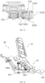
- the steering wheel assembly 56 further includes a switch 564 and an operating member 565.
- the switch 564 is electrically connected to the traveling motor to control the start or stop of the traveling motor.
- the operating member 565 includes a trigger portion 5651 for triggering the switch 564.
- the operating member 565 is rotatably connected to the steering wheel housing 563 about a second axis 1g.
- the operating member 565 is operated to cause the trigger portion 5651 of the operating member 565 to trigger the switch 564, thereby controlling the start or stop of the traveling motor to start or stop the vehicle-type driving device 100.
- the operating member 565 is connected to reset elements 566, and the reset elements 566 drive the operating member 565 to reset.
- the operating member 565 includes reset portions 5652 each of which is in contact with a respective reset element 566. When the operating member 565 is not pressed by an external force, the reset elements 566 cause the trigger portion 5651 of the operating member 565 to stop being in contact with the switch 564 and return to the initial position.
- the reset portion 5652 and the trigger portion 5651 are disposed on two sides of the second axis 1g, the reset element 566 is away from the trigger portion 5651, and the reset element 566 does not apply a force to the trigger portion 5651 so that the deformation of the trigger portion 5651 of the operating member 565 is reduced, the probability of trigger failure of the operating member 565 is reduced, and the service life of the operating member 565 is extended.
- the reset portion 5652 and the trigger portion 5651 are disposed on two sides of a plane passing through the second axis 1g and parallel to the first axis 1f.
- a main limiting portion 567 is further disposed on the steering wheel housing 563.
- the main limiting portion 567 is disposed on a side of the second axis 1g facing the trigger portion 5651.
- the main limiting portion 567 is configured to limit the displacement of the trigger portion 5651 when the trigger portion 5651 triggers the switch 564.
- the main limiting portion 567 is disposed on a side of the second axis 1g facing the trigger portion 5651 so that the switch 564 is prevented from being pressed too much, thereby extending the service life of the switch 564 and increasing the stroke by which the operating member 565 is pressed.
- the main limiting portion 567 is disposed on a side of the second axis 1g facing the trigger portion 5651 so that the deformation of the trigger portion 5651 of the operating member 565 is reduced, the deformation difference of the operating member 565 is transferred to an end away from the trigger portion 5651, and the stability of the contact between the trigger portion 5651 of the operating member 565 and the switch 564 is improved, thereby improving the reliability of the started traveling motor.
- the main limiting portion 567 includes a first limiting block 5671 and a second limiting block 5672, and the first limiting block 5671 is closer to the trigger portion 5651 of the operating member 565 than the second limiting block 5672.
- the operating member 565 is provided with a first limiting portion 5653 matching and limiting the first limiting block 5671 and a second limiting portion 5654 matching and limiting the second limiting block 5672, thereby increasing the limiting points of the operating member 565 and improving the reliability of controlling the stroke by which the operating member 565 is pressed.
- the first limiting block 5671 and the second limiting block 5672 protrude from the inner sidewall of the steering wheel housing 563, and the first limiting block 5671 is higher than the second limiting block 5672.
- the operating member 565 is provided with the first limiting portion 5653 and the second limiting portion 5654 in contact with the end surface of the first limiting block 5671 and the end surface of the second limiting block 5672.
- the first limiting portion 5653 includes a first limiting surface matching the end surface of the first limiting block 5671
- the second limiting portion 5654 includes a second limiting surface matching the end surface of the second limiting block 5672.
- the first limiting surface and the second limiting surface form a stepped surface on the surface of the operating member 565, and the structure is simple.
- an auxiliary limiting portion 568 is further disposed on the steering wheel housing 563, the auxiliary limiting portion 568 is disposed on a side of the second axis 1g facing the reset portion 5652, and the auxiliary limiting portion 568 is configured to limit the displacement of the trigger portion 5651 when the trigger portion 5651 triggers the switch 564.
- the auxiliary limiting portion 568 is used in conjunction with the main limiting portion 567, thereby increasing the limiting points of the operating member 565 and improving the reliability of controlling the stroke by which the operating member 565 is pressed.
- An end of the operating member 565 is disposed in the steering wheel housing 563, and the trigger portion 5651 is disposed at an end of the operating member 565.
- the other end of the operating member 565 extends out of the steering wheel housing 563 so that the operating member 565 can be toggled during operation.
- a hole is opened on the steering wheel housing 635, and the other end of the operating member 565 passes through the hole and is disposed on the outer side of the steering wheel housing 563.
- the hole wall of the hole is the auxiliary limiting portion 568.
- the operating member 565 includes a trigger 5657 and a toggle 5656.
- the trigger 5657 is rotatably connected to the steering wheel housing 563 about the second axis 1g.
- the trigger 5657 is rotatably connected to the steering wheel housing 563 about the second axis 1g.
- An end of the toggle 5656 is detachably connected to the trigger 5657, and the other end of the toggle 5656 is disposed on the outer side of the steering wheel housing 563.
- the trigger portion 5651 is disposed at an end of the trigger 5657 opposite to the toggle 5656. After the steering wheel assembly 56 is mounted, the toggle 5656 is set upward.
- the operating member 565 is configured to be a two-part structure, thereby facilitating the processing of the operating member 565.
- the trigger portion 5651 of the operating member 565 is configured to be a trapezoidal structure.
- the trigger portion 5651 is provided with a trigger surface for triggering the switch 564.
- a reinforced structure 5655 is disposed on a side of the trigger portion 5651 opposite to the trigger surface. The structure of the operating member 565 is improved, and the overall structural strength of the operating member 565 is increased.
- a spacer 569 is disposed between the switch 564 and the trigger portion 5651 of the operating member 565.
- the spacer 569 is elastic deformable to avoid wear caused by friction between the switch 564 and the operating member 565, thereby extending the service life of the operating member 565 and the switch 564.
- the spacer 569 is made of metal and has certain elasticity and good wear resistance. When the operating member 565 presses the switch 564, the spacer 569 also moves along with the operating member 565.
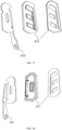
- FIG. 8A is a structural view illustrating that the operating member 565 does not trigger the switch 564
- FIG. 8B is a structural view illustrating that the operating member 565 triggers the switch 564. When the operating member 565 triggers the switch 564, the spacer 569 moves along with the operating member 565.
- the reset elements 566 assist the operating member 565 in resetting. In some examples, at least two reset elements 566 are provided to balance the forces on the operating member 565 and reduce the local elastic pressure of a single reset element 566 on the operating member 565.
- the switch 564 is a micro rocker switch. In some examples, the switch 564 includes a switch using a magnet, an inductor, or a potentiometer.
- the steering wheel 561 has three layers of structures that are a first layer structure 5611, a second layer structure 5612, and a rubber-coated structure 5613.
- the first layer structure 5611, the second layer structure 5612, and the rubber-coated structure 5613 are disposed in sequence from the inside to the outside.
- the first layer structure 5611 includes a metal insertion member and a steering wheel body made of hard rubber material connected to the metal insertion member.
- the steering wheel body is formed by injection moulding, and the metal insertion member is connected to the steering wheel body.
- the second layer structure 5612 is a layer of hard rubber injection-moulded on the outer side of the steering wheel body.
- the hard rubber is injection-moulded twice so that the main wall thickness of the steering wheel 561 is reduced, the cooling time is shortened, and the moulding cycle of the mould is short. Moreover, the initial shape of the steering wheel 561 is formed through the first injection moulding, and the second injection moulding strengthens the structural strength of the steering wheel body, thereby reducing the deformation of the steering wheel 561 during the production process. Finally, injection moulding is performed on the outer side of the steering wheel body injection-moulded twice to form the rubber-coated structure 5613. The soft rubber of the rubber-coated structure 5613 can improve the holding comfort of the user.
- a steering wheel rotary assembly 55 is connected to the steering wheel assembly 56, and the steering wheel rotary assembly 55 and the steering wheel assembly 56 can rotate simultaneously.
- the steering wheel rotary assembly 55 includes a steering wheel rotary shaft 551, which is a hollow shaft.
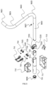
- a wire 553 of the switch 564 of the steering wheel assembly 56 can pass through the steering wheel rotary shaft 551 and then be electrically connected to other components. When the steering wheel 561 rotates, the wire 553 is not twisted as the steering wheel 561 turns, thereby reducing the wear rate of the wire 553 and extending the service life of the wire 553.
- a bushing 552 is disposed at an end of the steering wheel rotary shaft 551 facing away from the steering wheel assembly 56. An end of the bushing 552 is inserted into the end of the steering wheel rotary shaft 551, and the edge of the other end of the bushing 552 is an arc surface.
- the wire 553 passes through the bushing 552 and then is electrically connected to other components.
- the setting of the bushing 552 reduces the wear of the wire 553.
- the bushing 552 is fixed to the steering wheel rotary shaft 551 by bolts to prevent the bushing 552 from being separated from the steering wheel rotary shaft 551.
- the bushing 552 is made of plastic, thereby further reducing the wear of the wire 553.
- the steering wheel rotary assembly 55 further includes a magnet bracket 554 mounted at an end of the steering wheel rotary shaft 551 facing away from the steering wheel assembly 56.
- the magnet bracket 554 is a U-shaped structure bracket, an end of the magnet bracket 554 is connected to the steering wheel rotary shaft 551, the other end of the magnet bracket 554 is used for fixing and mounting a steering wheel magnet 557, and the magnet bracket 554 can avoid the wire 553 passing through the steering wheel rotary shaft 551.
- the magnet bracket 554 provides an installation carrier for the steering wheel magnet 557.
- the magnet bracket 554 is made of plastic.
- the metal block is placed in a processing mould and injection-moulded to form the magnet bracket 554.
- the metal block is embedded into the magnet bracket 554, and then the metal block is magnetized to form the steering wheel magnet 557, thereby ensuring the magnetism of the steering wheel magnet 557 and improving the strength with which the steering wheel magnet 557 is fixed.
- a circuit board mounting housing 556 is disposed on a side the steering wheel magnet 557 faces.
- the circuit board mounting housing 556 covers an end of the steering wheel rotary shaft 551 facing away from the steering wheel assembly 56.
- An angle detection circuit board 555 is disposed in the circuit board mounting housing 556.
- An angle detection sensor is disposed on the angle detection circuit board 555. Since the steering wheel magnet 557 and the steering wheel rotary shaft 551 are coaxial, the angle detection sensor is disposed in the middle of the angle detection circuit board 555, and the structure is compact.
- the magnet bracket 554 is mounted on the steering wheel rotary shaft 551 and is rotatable with the steering wheel rotary shaft 551. Therefore, the steering wheel magnet 557 is also rotatable with the steering wheel rotary shaft 551, thereby improving the detection accuracy of the steering angle of the steering wheel 561.
- Glue is filled into the circuit board mounting housing 556 to seal the angle detection circuit board 555.
- the pins and other plug connectors on the angle detection circuit board 555 are disposed on the outer side of the circuit board mounting housing 556 after being filled with glue, thereby facilitating plugging and unplugging with other connecting wires.
- the steering wheel rotary assembly 55 is connected to a steering wheel rotary damping assembly 54, and the steering wheel rotary damping assembly 54 provides resistance to the rotation of the steering wheel rotary assembly 55 to enhance the comfort of the user turning the steering wheel 561.
- the steering wheel rotary damping assembly 54 includes a transmission wheel 541 and a transmission belt 542.
- the transmission wheel 541 includes a first transmission wheel and a second transmission wheel mounted on the steering wheel rotary shaft 551.
- the first transmission wheel and the second transmission wheel are drivingly connected by the transmission belt 542.
- the first transmission wheel is a drive wheel driven by the user to rotate, and the second transmission wheel is a driven wheel.
- the steering wheel rotary damping assembly 54 further includes a tensioner adjustment mechanism 543 for adjusting the tightness on the transmission belt 542 so that the rotational resistance between the first transmission wheel and the second transmission wheel can be adjusted.
- the tensioner adjustment mechanism 543 includes a tensioner pulley 5431 in contact with the transmission belt 542.
- the tensioner pulley 5431 is mounted onto a tensioner pulley bracket 5432, the tensioner pulley bracket 5432 is supported on a support plate 5433, and a side of the tensioner pulley bracket 5432 is in contact with the support plate 5433.
- the tensioner pulley bracket 5432 is movable relative to the support plate 5433, thereby adjusting the position of the tensioner pulley 5431 relative to the transmission belt 542.
- the tensioner pulley bracket 5432 is provided with a locking member 5434, and the locking member 5434 can fix the tensioner pulley bracket 5432 to the support plate 5433.
- first serration is disposed on the support plate 5433
- second serration meshing with the first serration is disposed on the tensioner pulley bracket 5432 so that the friction between the support plate 5433 and the tensioner pulley bracket 5432 is increased, and the locking member 5434 can stably fix the tensioner pulley bracket 5432 to the support plate 5433.
- the locking member 5434 includes a pressure plate and a bolt.
- An elongated hole is disposed on a side of the tensioner pulley bracket 5432 facing away from the support plate 5433.
- the pressure plate is disposed above the elongated hole.
- the bolt passes through the pressure plate and the elongated hole and can abut against the support plate 5433. After the position of the tensioner pulley 5431 is adjusted, the bolt is tightened to transmit the force to the tensioner pulley bracket 5432 through the pressure plate so that the tensioner pulley bracket 5432 abuts against the support plate 5433.
- the body 100a of the vehicle-type driving device 100 further includes an accelerator module 60, and the accelerator module 60 includes a pedal assembly 61 and an accelerator assembly 62.
- the user steps on the pedal assembly 61 to control the accelerator assembly 62 to control the amount of power or fuel supplied to the vehicle-type driving device 100, thereby controlling the traveling speed of the vehicle-type driving device 100.
- the pedal assembly 61 includes a pedal body 611 and a pedal bracket 612.
- the pedal bracket 612 is a metal part, and an end of the pedal bracket 612 is connected to the accelerator assembly 62.
- the pedal body 611 is a rubber part, and the pedal body 611 is used for the driver to step on.
- the other end of the pedal bracket 612 is provided with a mounting groove, the pedal body 611 is disposed in the mounting groove, and the pedal body 611 is connected to the mounting groove through the structure of a plug-in groove and a plug-in block.
- the connection structure is simple so that it is convenient to assemble the pedal body 611 on the pedal bracket 612.
- the accelerator assembly 62 includes a fixing bracket 621 which serves as an installation carrier. Other components of the accelerator assembly 62 are all disposed on the fixing bracket 621 so that a modular arrangement of the accelerator module 60 is achieved, and the accelerator module 60 can be removed or mounted as a whole.
- an accelerator housing 626 is disposed on the fixing bracket 621, and a mounting cavity 6263 and a pedal circuit board mounting cavity 6262 are disposed in the accelerator housing 626.
- a main shaft 622 is rotatably disposed in the mounting cavity 6263.
- the main shaft 622 is rotatably connected to the fixing bracket 621, and an end of the main shaft 622 extends out of the accelerator housing 626 and is fixedly connected to the pedal bracket 612.
- the pedal bracket 612 drives the main shaft 622 to rotate.
- the accelerator housing 626 includes a dustproof box 6267 and a pedal circuit board mounting box 6268 disposed on a side of the dustproof box 6267.
- the pedal circuit board mounting box 6268 is mounted on the fixing bracket 621.
- the pedal circuit board mounting box 6268 has the pedal circuit board mounting cavity 6262 for mounting a pedal circuit board 627.
- An opening is provided on a side of the pedal circuit board mounting box 6268 facing away from the dustproof box 6267 to facilitate the installation of the pedal circuit board 627.
- the dustproof box 6267 includes an upper dustproof box and a lower dustproof box that are detachably connected.
- the lower dustproof box is mounted on the fixing bracket 621, and the upper dustproof box and the lower dustproof box are buckled to form the mounting cavity 6263, which has the sealing and dustproof performances.
- the pedal circuit board 627 is mounted in the pedal circuit board mounting box 6268. Glue is filled into the pedal circuit board mounting cavity 6262 to seal the opening of the pedal circuit board mounting box 6268 so that the waterproof performance is ensured. No dust is accumulated at a pedal magnet 628, thereby avoiding the failure of the angle detection sensor.
- a circular cavity 6264 is disposed on the pedal circuit board mounting box 6268, and the circular cavity 6264 connects the mounting cavity 6263 to the pedal circuit board mounting cavity 6262.
- the other end of the main shaft 622 extends out of the dustproof box 6267 through the circular cavity 6264, and the end of the main shaft 622 is disposed in the circular cavity 6264.
- the pedal magnet 628 is disposed at the end of the main shaft 622, and the pedal magnet 628 is disposed in the circular cavity 6264.
- the pedal circuit board 627 is disposed in the pedal circuit board mounting cavity 6262.
- the angle detection sensor is disposed at the position of the pedal circuit board 627 corresponding to the pedal magnet 628 and is configured to acquire the angle of rotation of the main shaft 622 and then acquire the opening degree of the pedal assembly 61.
- a first sealing rib 6265 circumferentially protrudes on a side of the pedal circuit board mounting box 6268 facing away from the opening, and the first sealing rib 6265 is in contact with the surface of the dustproof box 6267, thereby improving the sealing and dustproof performance of the pedal circuit board mounting box 6268.
- a second sealing rib 6266 circumferentially protrudes at an end of the circular cavity 6264 facing the dustproof box 6267, and the second sealing rib 6266 is in contact with the surface of the dustproof box 6267, thereby preventing dust and other impurities from entering the circular cavity 6264 and affecting the detection accuracy of the angle detection sensor and improving the sealing and dustproof performance of the pedal circuit board mounting box 6268.
- a main shaft bracket 623 is further disposed in the dustproof box, and the main shaft bracket 623 is mounted on the main shaft 622.
- the main shaft bracket 623 includes two annular parts that are opposite to each other and in parallel. The two annular parts are partially connected by a connector to form a space for the main shaft 622 to pass through. The other end of the main shaft 622 passes through the two annular parts of the main shaft bracket 623 and the dustproof box and is disposed in the pedal circuit board mounting cavity 6262.
- main shaft bushings 624 are disposed at two opposite ends of the main shaft bracket 623, respectively.
- the main shaft bushings 624 fit the annular parts of the main shaft bracket 623, and the main shaft bushings 624 are sleeved on the main shaft 622.
- the main shaft bushings 624 reduce the radial and axial movement of the main shaft 622 and improve the accuracy of the signal received by the angle sensor.
- the main shaft 622 is further connected to a rotary bracket 625 mounted on the main shaft 622 between the two annular parts.
- the rotary bracket 625 includes a U-shaped bracket 6251 and a limiting bracket 6252.
- the main shaft 622 is disposed in a U-shaped groove of the U-shaped bracket 6251.
- the limiting bracket 6252 is an S-shaped bracket. An end of the limiting bracket 6252 fits and is connected to a side of the U-shaped bracket 6251, and the other end of the limiting bracket 6252 is used for being in contact with a pedal limiting portion 6261 on the fixing bracket 621.
- the U-shaped bracket 6251 and the limiting bracket 6252 are rotatable with the main shaft 622.
- the pedal limiting portion 6261 limits the rotation range of the main shaft 622.
- An end of the limiting bracket 6252 is connected to a pedal elastic member 629, and the pedal elastic member 629 always has a tendency to reset the main shaft 622 and thus reset the pedal assembly 61.
- the pedal elastic member 629 assists the main shaft 622 in resetting, and at the same time, the pedal limiting portion 6261 limits the position where the main shaft 622 is reset.
- two pedal elastic members 629 are provided. When one pedal elastic member 629 loses the elastic force, the other pedal elastic member 629 can still play a resetting role, thereby avoiding the following risk: one pedal elastic member 629 is damaged and the pedal assembly 61 immediately fails in resetting.
- the pedal elastic member 629 is a spring. If two springs are provided, the two springs may be coaxial with one spring being disposed inside the other spring.
- the power supply assembly 96 continues supplying power until the power supply assembly 96 is completely discharged or the power is too low, causing the vehicle-type driving device 100 to be powered off. If a brake pedal is not stepped on to a preset position, the traveling wheels are movable freely, and the vehicle-type driving device 100 coasts.
- the vehicle-type driving device 100 is provided with a first energy storage device 101 and a second energy storage device 107.
- the traveling assembly 93 includes multiple traveling wheels.
- the multiple traveling wheels are a first left traveling wheel, a second left traveling wheel, a first right traveling wheel, and a second right traveling wheel, respectively.
- a traveling motor 104 drives the traveling assembly 93 to provide power for the vehicle-type driving device 100 to travel.
- the first energy storage device 101 is configured to supply power to at least the traveling motor 104 so that the traveling motor 104 drives the traveling assembly 93 to operate
- the second energy storage device 107 is configured to, when the power of the first energy storage device 101 is less than a preset value and/or when an electrical energy transmission path from the first energy storage device 101 to the traveling motor 104 fails or is cut off, serve as an electric power source to control the traveling motor 104 to enter the parking mode.
- the first energy storage device 101 in the vehicle-type driving device 100 can supply power to the traveling motor 104 so that the traveling motor 104 drives the traveling assembly 93 to operate, and the first energy storage device 101 in the vehicle-type driving device 100 can serve as an electric power source to control the traveling motor 104 to enter the parking mode.
- the power of the first energy storage device 101 is greater than or equal to the preset value, the first energy storage device 101 serves as the electric power source so that a drive control unit controls the traveling motor 104 to enter the parking mode.
- the second energy storage device 107 serves as the electric power source to control the traveling motor 104 to enter the parking mode so that the vehicle-type driving device 100 can be in the parking mode for a long time.
- Failures occurring on the electrical energy transmission path from the first energy storage device 101 to the traveling motor 104 include cell damage, battery management system damage, temperature faults, insulation faults, blown fuses, and the like. Failures occurring on the electrical energy transmission path may result in low power, sudden power loss, or electrical disconnects within a power supply system.
- the electrical energy transmission path from the first energy storage device 101 to the traveling motor 104 is cut off.
- the second energy storage device 107 is provided so that the problem that the vehicle-type driving device 100 coasts in the event of the complete power failure, sudden power loss, or low power of the power supply system is solved, thereby improving safety.
- the vehicle-type driving device 100 further includes a control device 103, the control device 103 includes a controller unit 105 and a drive control unit, and the controller unit 105 can control the drive control unit so that the traveling motor 104 drives the traveling assembly 93 to operate.
- the controller unit 105 includes a controller and some related circuits.
- the circuit structure of the controller unit 105 is the related art and thus is not specifically limited here.
- the drive control unit includes a switching element and a drive unit 106.
- the switching element is powered and triggered to control the traveling motor 104 to enter the parking mode.
- the drive unit 106 includes a relay and some related circuits, and the circuit structure is the related art and thus is not specifically limited here.
- the switching element includes an inverter 109.
- the first energy storage device 101 serves as the electric power source so that the drive control unit controls the traveling motor 104 to enter the parking mode.
- the relay of the drive control unit is closed, and the controller operates to control the inverter 109 to operate to achieve electronic parking.
- the second energy storage device 107 serves as the electric power source so that the drive control unit controls the traveling motor 104 to enter the parking mode. Three phases of the traveling motor 104 are short-circuited so that the traveling motor 104 enters the parking mode.
- the controller stops working, the relay of the drive unit 106 is open, and the second energy storage device 107 supplies power to the drive unit so that the lower-bridge metal-oxide-semiconductor field-effect transistor (MOSFET) of the inverter 109 is turned on, and the phase lines of the traveling motor 104 are short-circuited to form a braking force.
- MOSFET metal-oxide-semiconductor field-effect transistor
- the second energy storage device 107 includes a capacitive power supply 107a.
- the first energy storage device 101 can charge the capacitive power supply 107a.
- the capacitive power supply 107a serves as the electric power source so that the drive unit controls the traveling motor 104 to enter the parking mode. In this manner, the problem that the vehicle-type driving device coasts in the event of the complete power failure of the control system is solved.
- the second energy storage device 107 further includes a first energy storage assembly 107b, where when the traveling assembly 93 coasts, the back electromotive force generated by the traveling motor 104 charges the first energy storage assembly 107b, and the first energy storage assembly 107b charges the capacitive power supply 107a when the power of the capacitive power supply 107a is less than a preset power value.
- the first energy storage assembly 107b is provided.
- the traveling motor 104 cannot be braked, the vehicle-type driving device 100 slides, and the traveling motor 104 starts to rotate; the back electromotive force generated by the rotation of the traveling motor 104 can charge the first energy storage assembly 107b; when the stored power of the first energy storage assembly 107b reaches a set value, the first energy storage assembly 107b starts to charge the capacitive power supply 107a.
- the vehicle-type driving device 100 includes a capacitive switch 108 configured to disconnect or connect the capacitive power supply 107a.
- the first energy storage device 101 includes a battery pack. When the user removes the battery pack from the vehicle-type driving device 100, the battery pack is electrically disconnected from the vehicle-type driving device 100, and the user may manually operate the capacitive switch 108 to disconnect the capacitive power supply 107a so that the capacitive power supply 107a is discharged.
- the capacitive switch 108 automatically controls the capacitive power supply 107a to be disconnected and discharged. In this manner, the traveling motor 104 exits the state in which the three phases of the traveling motor 104 are short-circuited, and the user can push the vehicle-type driving device 100 when the battery pack is removed, which is convenient for operation. When the user places the battery pack into the vehicle-type driving device 100, the battery pack is electrically connected to the vehicle-type driving device 100, and the user may manually operate the capacitive switch 108 to connect the capacitive power supply 107a. In some examples, the capacitive switch 108 automatically controls the capacitive power supply 107a to be connected.
- the second energy storage device 107 can serve as the electric power source to control the traveling motor 104 to enter the parking mode, thereby improving safety.
- the second energy storage device 107 includes a second energy storage assembly 107c.
- the second energy storage assembly 107c serves as the electric power source so that the drive unit controls the traveling motor 104 to enter the parking mode.
- the second energy storage assembly 107c supplies power to the drive unit so that the lower-bridge MOSFET of the inverter 109 is turned on, and the phase lines of the traveling motor 104 are short-circuited to form the braking force.
- the preceding parking mode is a mode in which the traveling motor 104 slows down or stops.
- the traveling motor 104 slows down, the vehicle-type driving device 100 slides continuously or discontinuously at a very low speed and does not slide down the slope to a large extent, thereby improving safety.
- a detection device 102 determines whether the power of the first energy storage device 107 is less than the preset value and/or whether the electrical energy transmission path from the first energy storage device 101 to the traveling motor 104 fails or is cut off.
- the first energy storage device 101 serves as an electric power source to control the vehicle-type driving device 100 to enter the parking mode.
- step S3 when the power of the first energy storage device 107 is less than or equal to the preset value and/or when the electrical energy transmission path from the first energy storage device 101 to the traveling motor 104 fails or is cut off, the second energy storage device 107 serves as an electric power source to control the vehicle-type driving device 100 to enter the parking mode.
- the detection device 102 determines whether the power of the second energy storage device 107 is exhausted, or determines whether the power of the second energy storage device 107 is less than or equal to the preset value, or determines whether the voltage of the second energy storage device 107 is less than or equal to the preset value. If the determination result is no, the second energy storage device 107 continues serving as the electric power source to control the vehicle-type driving device 100 to enter the parking mode.
- step S5 when the power of the second energy storage device 107 is exhausted, or when the power of the second energy storage device 107 is less than or equal to the preset value, or when the voltage of the second energy storage device 107 is less than or equal to the preset value, the vehicle-type driving device 100 slides on the slope to supply power to the second energy storage device 107.
- step S6 the detection device 102 determines whether the power or voltage of the second energy storage device 107 increases enough to enable the vehicle-type driving device 100 to enter the parking mode. If the determination result is no, the vehicle-type driving device 100 continues sliding on the slope to supply power to the second energy storage device 107. If the determination result is yes, the second energy storage device 107 serves as the electric power source to control the vehicle-type driving device 100 to enter the parking mode.
- the specific structures of the first energy storage device 101, the first energy storage assembly 107b, and the second energy storage assembly 107c mentioned above are the related arts, and the details are not repeated here.
- the vehicle-type driving device 100 is the riding mower, the mower has the cutting assembly 10, and the chassis 91 supports the cutting assembly 10.
- the cutting assembly 10 includes the mowing elements 12 for mowing grass, and the cutting motors 13 are configured to drive the cutting assembly 10.
- the mowing elements 12 are prone to loosening, so it is necessary to detect whether the mowing elements 12 are abnormal before the cutting assembly 10 operates.
- the detection device 102 is configured to detect a first operating parameter and a second operating parameter of the cutting motor 13.
- the control device 103 is used for controlling the cutting motor 13 to stop or slow down when the first operating parameter is within a first threshold range, the second operating parameter is within a second threshold range, and the duration that the first operating parameter is within the first threshold range and the second operating parameter is within the second threshold range is a first preset time.
- the second operating parameter is different from the first operating parameter, and the second operating parameter includes at least the rotational speed of the cutting motor 13.
- the detection device 102 acquires the first operating parameter and the second operating parameter of the cutting motor 13, and the second operating parameter includes at least the rotational speed of the cutting motor 13.
- the cutting motor 13 stops or slows down.
- the rotational speed of the cutting motor 13 is used as one of the conditions for determining whether the cutting assembly 10 fails, thereby avoiding the problem that the cutting motor 13 operates at a low speed, and the cutting assembly 10 is easily misjudged as abnormal due to too small a working current of the cutting motor 13.
- the present application improves the accuracy of determining whether the cutting assembly 10 works normally, thereby improving the usage safety of the mower.
- control device 103 controls the cutting motor 13 to stop in a second preset time.
- the second preset time is greater than the first preset time.
- the second preset time provides the buffer time for the shutdown of the cutting motor 13 to avoid the impact of the sudden shutdown on the cutting motor 13.
- the second preset time is greater than 1s, thereby ensuring that the cutting motor 13 is controlled to slow down within a certain period of time until the cutting motor 13 stops without causing damage to the surrounding environment or the operator.
- the second operating parameter includes the actual rotational speed and the target rotational speed of an electric motor
- the second threshold range includes an actual rotational speed range and a target rotational speed range of the electric motor.
- the preceding first operating parameter includes the bus current.
- the bus current is relatively small, whether the cutting assembly fails is reflected through the actual rotational speed and the target rotational speed of the electric motor.
- the first threshold range is (0 A, 3 A].
- the actual rotational speed range of the electric motor is greater than or equal to 500 r/min, and the target rotational speed range of the electric motor is greater than or equal to 1950 r/min.
- the second operating parameter includes the actual rotational speed and the target rotational speed of an electric motor
- the second threshold range includes an actual rotational speed range and a target rotational speed range of the electric motor.
- the preceding first operating parameter includes the phase current.
- the phase current is relatively small, whether the cutting assembly 10 fails is reflected through the actual rotational speed of the cutting motor 13 and the target rotational speed of the cutting motor 13.
- the first threshold range is (0 A, 4 A].
- the actual rotational speed range of the electric motor is greater than or equal to 500 r/min, and the target rotational speed range of the electric motor is greater than or equal to 1950 r/min.
- the mower further includes a display screen, a switch panel, and a battery management system.
- the control device 103 controls the cutting motor 13 to start, whether the traveling motor 104 for driving the traveling assembly 93 to operate, the display screen, the switch panel, and the battery management system communicate normally with the control device 103 separately is determined; and if so, the cutting motor 13 starts. If any one of the traveling motor 104 for driving the traveling assembly 93 to operate, the display screen, the switch panel, and the battery management system communicates abnormally with the control device 103, the cutting motor 13 cannot start, thereby ensuring the safety of the mower during operation.
- step S1010 the detection device 102 detects whether the phase current is less than or equal to 4 A or whether the bus current is less than or equal to 3 A. If the determination result is no, the determination ends. If the determination result is yes, in step S1020, the detection device 102 detects whether the actual rotational speed of the electric motor is greater than or equal to 500 r/min and the target rotational speed of the electric motor is greater than or equal to 1950 r/min. If the determination result is no, the determination ends. If the determination result is yes, in step S1030, the detection device 102 detects whether the duration that the first operating parameter is within the first threshold range and the second operating parameter is within the second threshold range is greater than 1s. If the determination result is no, the determination ends. If the determination result is yes, in step S1040, the control device 103 controls the cutting motor 13 to stop or slow down.
- the preceding switch panel is a control panel for controlling the start and stop of the mower, and the structure of the switch panel is the related art and is not specifically limited here.
- the communication connection between the traveling motor 104, the display screen, the switch panel, and the battery management system and the control device 103 is the related art and is not specifically limited here.
- the cutting assembly 10 does not perform a mowing operation.
- the rotational speed of the traveling motor 104 driving the traveling assembly 93 to operate is relatively high. If the rotational speed of the traveling motor 104 is greater than a preset rotational speed value, the cutting motor 13 stops, thereby ensuring the safety of the operating environment.
- the vehicle-type driving device 100 usually decelerates during turning. To improve the stability of the speed reduction of the vehicle-type driving device 100 during turning and the driving safety of the vehicle-type driving device 100, in some examples, the performance of the vehicle-type driving device 100 decelerating during turning is improved, thereby improving the user experience.
- the vehicle-type driving device 100 includes a speed setting device and the traveling motor 104.
- the speed setting device is used for the user to set the traveling speed of the vehicle-type driving device 100.
- the traveling speed set by the speed setting device is defined as the input speed.
- the traveling motor 104 drives the vehicle-type driving device 100 to travel at the target speed, where the target speed is the actual traveling speed of the vehicle-type driving device 100.
- the ratio of the target speed to the input speed is defined as the conversion ratio.
- the control device 103 can set the conversion ratio according to the steering angle of the steering wheel 561.
- the control device 103 sets the conversion ratio to a first steering conversion ratio; and when the steering wheel 561 has a second steering angle, the control device 103 sets the conversion ratio to a second steering conversion ratio, where the second steering conversion ratio is different from the first steering conversion ratio.
- the preset range may be an open interval or a half-open interval.
- This driving method may be applied to the cruise mode of the vehicle-type driving device 100 and, of course, may be applied to other driving modes, which is not specifically limited here.
- the conversion ratio is obtained using the target speed and the input speed. Different steering angles of the steering wheel 561 correspond to different conversion ratios.
- the conversion ratio is acquired according to the steering angle of the steering wheel 561, and then the target speed of the vehicle-type driving device 100 is adjusted according to the conversion ratio so that the traveling speed of the vehicle-type driving device 100 can steadily decrease during turning, and the driver does not feel a shock due to the sudden decrease or increase in speed, thereby improving the driving safety and the user experience of the vehicle-type driving device 100.
- the vehicle-type driving device 100 includes a steering process and a straightening-out process.
- the steering process includes a first steering stage and a second steering stage.
- the steering angle in the first steering stage is the first steering angle
- the steering angle in the second steering stage is the second steering angle.
- the first steering conversion ratio remains unchanged when the vehicle-type driving device 100 is in the first steering stage.
- the second steering conversion ratio changes linearly when the vehicle-type driving device 100 is in the second steering stage.
- the vehicle-type driving device 100 can set different conversion ratios according to the steering angles so that the traveling speed of the vehicle-type driving device 100 is adjusted, thereby improving the driving safety and the user experience of the vehicle-type driving device 100.
- the first steering conversion ratio when the first steering angle is greater than or equal to 0° and less than or equal to 25°, the first steering conversion ratio is 100%.
- the first steering conversion ratio is a fixed value.
- the second steering angle is greater than 25° and less than or equal to 180°.
- the vehicle-type driving device 100 adjusts the speed to the target speed, thereby achieving the deceleration of the vehicle-type driving device 100.
- the steering wheel 561 is capable of controlling the vehicle-type driving device 100 to straighten out, and a direction in which the vehicle-type driving device 100 straightens out is opposite to a direction in which the vehicle-type driving device 100 steers.
- the minimum speed of the vehicle-type driving device 100 during the steering process is acquired, where the minimum speed is set to the initial target speed of the vehicle-type driving device 100 during the straightening-out process.
- the control device 103 sets the conversion ratio to a first straightening-out conversion ratio; and when the steering wheel 561 has a second straightening-out angle, the control device 103 sets the conversion ratio to a second straightening-out conversion ratio, where the second straightening-out conversion ratio is different from the first straightening-out conversion ratio.
- the vehicle-type driving device 100 can set different conversion ratios according to the straightening-out angles so that the traveling speed of the vehicle-type driving device 100 is adjusted, thereby improving the driving safety and the user experience of the vehicle-type driving device 100.
- the straightening-out process of the vehicle-type driving device 100 includes a first straightening-out stage and a second straightening-out stage, where a straightening-out angle in the first straightening-out stage is the first straightening-out angle, a straightening-out angle in the second straightening-out stage is the second straightening-out angle, the first straightening-out conversion ratio remains unchanged when the vehicle-type driving device 100 is in the first straightening-out stage, and the second straightening-out conversion ratio changes linearly when the vehicle-type driving device 100 is in the second straightening-out stage.
- the vehicle-type driving device 100 is in the first straightening-out stage, the angle of rotation of the steering wheel 561 is relatively large, and the conversion ratio remains unchanged.
- the vehicle-type driving device 100 travels at the minimum speed during turning in the first straightening-out stage to avoid the problem of overshooting during turning, thereby improving the driving comfort and safety of the driver.
- the conversion ratio may be increased, thereby increasing the traveling speed of the vehicle-type driving device 100 to improve the working efficiency of the vehicle-type driving device 100.
- the first straightening-out conversion ratio when the first straightening-out angle is greater than or equal to 25° and less than or equal to 180°, the first straightening-out conversion ratio is 30%. In some examples, when the second straightening-out angle is greater than or equal to 0° and less than or equal to 25°, the second straightening-out conversion ratio changes from 30% to 100% within a preset time. The preset time is 3.5s. Under the premise that the driving safety is not affected in the second stage of straightening out, the vehicle-type driving device 100 accelerates to the set traveling speed within 3.5s.
- step S1110 when the steering angle is greater than or equal to 0° and less than or equal to 25°, the traveling speed of the vehicle-type driving device 100 remains unchanged.
- step S1120 when the steering angle is greater than or equal to 25° and less than or equal to 180°, the traveling speed of the vehicle-type driving device 100 changes with the linearly changing conversion ratio. It is to be understood that during the steering process, when the steering angle is 180°, the conversion ratio is the minimum during the steering process, and the traveling speed of the vehicle-type driving device 100 is the lowest.
- step S2100 when the steering angle is greater than or equal to 25° and less than or equal to 180°, the control device 103 controls the vehicle-type driving device 100 with the minimum conversion ratio ever occurring within this range.
- step S2120 when the steering angle is greater than or equal to 0° and less than or equal to 25°, the traveling speed of the vehicle-type driving device 100 gradually changes with the conversion ratio over time.
- the steering wheel 561 is configured to control the vehicle-type driving device 100 to steer, and a driving device drives the vehicle-type driving device 100 to steer at a target angular velocity.
- the ratio of the target angular velocity to the change in the steering angle of the steering wheel 561 is defined as a steering ratio.
- the control device is configured to, when the traveling speed of the vehicle-type driving device 100 is within a preset range, set the steering ratio according to a steering ratio curve function, where the variables of the steering ratio curve function include the steering angle of the steering wheel 561 and the traveling speed of the vehicle-type driving device 100.
- the change in the angle of the steering wheel 561 is the difference between the angle of the steering wheel 561 after the change and the initial angle of the steering wheel 561.
- the initial angle of the steering wheel 561 is the angle of the steering wheel 561 when the vehicle-type driving device 100 moves straight, that is, 0°.
- the steering ratio is the ratio of the target angular velocity to the change in the steering angle of the steering wheel 561.
- the steering ratio is set according to the steering ratio curve function when the traveling speed is within the preset range, and then the traveling speed of the vehicle-type driving device 100 is determined according to the steering ratio and the steering angle of the steering wheel 561.
- the vehicle-type driving device 100 travels according to the traveling speed. In this manner, the traveling speed of the vehicle-type driving device 100 is adjusted according to the steering angle of the steering wheel 561 so that the steering feel of the vehicle-type driving device 100 at different speeds can be improved, the problem of poor operating feel for a driver driving and turning can be solved, and the operating experience of the user can be improved.
- the steering ratio curve function includes a low-speed steering ratio curve function and a high-speed steering ratio curve function
- the preset range includes a low-speed driving threshold and a high-speed driving threshold, where when the traveling speed is less than the low-speed driving threshold, a low-speed steering ratio is set according to the low-speed steering ratio curve function; and when the traveling speed is greater than the high-speed driving threshold, a high-speed steering ratio of the traveling wheel is set according to the high-speed steering ratio curve function.
- the traveling speed of the vehicle-type driving device 100 is adjusted according to different steering ratio curves, thereby improving the operating comfort of the driver driving the vehicle-type driving device 100 to steer.
- the maximum traveling speed of the vehicle-type driving device 100 is greater than or equal to 11 km/h and less than or equal to 14 km/h, the low-speed driving threshold is 20% of the maximum traveling speed, and the high-speed driving threshold is 90% of the maximum traveling speed. In some examples, the low-speed driving threshold is 60% of the maximum traveling speed, and the high-speed driving threshold is 80% of the maximum traveling speed.
- the traveling wheels include left traveling wheels and right traveling wheels.
- the low-speed steering ratio curve function includes a left-wheel low-speed steering ratio curve function and a right-wheel low-speed steering ratio curve function.
- the traveling speed of the left traveling wheel is less than the low-speed driving threshold
- the low-speed steering ratio of the left traveling wheel is set according to the left-wheel low-speed steering ratio curve function.
- the traveling speed of the right traveling wheel is less than the low-speed driving threshold
- the low-speed steering ratio of the right traveling wheel is set according to the right-wheel low-speed steering ratio curve function.
- the left-wheel low-speed steering ratio curve function corresponds to the left wheel-low curve in FIG. 34
- the right-wheel low-speed steering ratio curve function corresponds to the right wheel-low curve in FIG. 34 .
- the high-speed steering ratio curve function includes a left-wheel high-speed steering ratio curve function and a right-wheel high-speed steering ratio curve function.
- the high-speed steering ratio of the left traveling wheel is set according to the left-wheel high-speed steering ratio curve function.
- the traveling speed of the right traveling wheel is greater than the high-speed driving threshold, the high-speed steering ratio of the right traveling wheel is set according to the right-wheel high-speed steering ratio curve function.
- the left-wheel high-speed steering ratio curve function corresponds to the left wheel-high curve in FIG. 34
- the right-wheel high-speed steering ratio curve function corresponds to the right wheel-high curve in FIG. 34 .
- different steering ratios are set for the traveling wheels at different positions at different traveling speeds.
- the traveling speed of the traveling wheel is adjusted in a targeted manner according to the set steering ratio so that the steering feel of the vehicle-type driving device 100 at different speeds can be greatly improved.
- the traveling speed of the vehicle-type driving device 100 is between the low-speed driving threshold and the high-speed driving threshold, the low-speed steering ratio in the low-speed steering ratio curve function and the high-speed steering ratio in the high-speed steering ratio curve function are determined according to the steering angle of the steering wheel 561, and the steering ratio curve function at the traveling speed is determined according to the low-speed steering ratio and the high-speed steering ratio.
- the traveling speed of the vehicle-type driving device 100 is between the low-speed driving threshold and the high-speed driving threshold, the steering ratio at the traveling speed is calculated, the target angular velocity is determined according to the steering ratio and the change in the steering angle of the steering wheel 561, and then the traveling speed of the vehicle-type driving device 100 is updated and adjusted according to the target angular velocity.
- Ratio_SpeedLow denotes the low-speed steering ratio
- Ratio_SpeedHigh denotes the high-speed steering ratio
- ratio denotes a steering ratio coefficient of the steering wheel 561, and the ratio is greater than or equal to 0 and less than or equal to 1.
- the steering ratio at the current speed is calculated according to the corresponding low-speed steering ratio in the low-speed steering ratio curve function at this angle and the corresponding high-speed steering ratio in the high-speed steering ratio curve function at this angle, and the target angular velocity is obtained according to the calculated steering ratio curve.
- the low-speed steering ratio curve function corresponds to the low steering ratio curve in FIG. 33
- the high-speed steering ratio curve function corresponds to the high steering ratio curve in FIG. 33 .
- A_Speed denotes the traveling speed of the vehicle-type driving device 100
- TH_L denotes the low-speed driving threshold
- TH_H denotes the high-speed driving threshold
- step S2101 the detection device 102 determines whether the current traveling speed of the vehicle-type driving device 100 is less than 20% of the maximum traveling speed. If the determination result is yes, the steering ratio is acquired using the low-speed steering ratio curve function. If the determination result is no, in step S2102, the detection device 102 determines whether the current traveling speed of the vehicle-type driving device 100 is greater than 90% of the maximum traveling speed. If the determination result is yes, the steering ratio is acquired using the high-speed steering ratio curve function.
- the steering ratio coefficient is calculated according to the actual traveling speed of the vehicle-type driving device 100, and the steering ratio curve of the vehicle-type driving device 100 at the current traveling speed is obtained according to the calculated steering ratio coefficient, the low-speed steering ratio curve function, and the high-speed steering ratio curve function.
- the steering ratio is small; and when the vehicle-type driving device 100 travels at a low speed, the steering ratio is large. In this manner, the user feels comfortable when operating the vehicle-type driving device 100 to steer, without any sense of resistance or pulling.
- the vehicle-type driving device 100 When the vehicle-type driving device 100 is in operation, the energy stored in the first energy storage device 101 is consumed. The vehicle-type driving device 100 reduces some performances of the vehicle-type driving device 100 when the residual energy stored in the first energy storage device 101 is relatively low.
- the first energy storage device 101 is the power supply assembly 96.
- the first energy storage device 101 supplies power to the traveling motor 104 and the cutting motor 13.
- the detection device 102 detects the voltage or the remaining power of the first energy storage device 101.
- the detection device 102 detects the amount of substance, current, or internal pressure of the first energy storage device 101. The values detected by the detection device 102 are not limited, as long as the power state of the first energy storage device 101 can be detected.
- the first energy storage device 101 has a normal state and a low power state. When the voltage or the remaining power of the first energy storage device 101 is higher than a first preset level, the first energy storage device 101 is in the normal state. When the voltage or the remaining power of the first energy storage device 101 is lower than or equal to the first preset level, the first energy storage device 101 is in the low power state.
- the control device 103 controls the output states of the traveling motor 104 and the cutting motor 13.
- the output states of the traveling motor 104 and the cutting motor 13 include the torque, the maximum rotational acceleration, and the maximum rotational speed of the traveling motor 104 and the cutting motor 13.
- the user starts the vehicle-type driving device 100 in step S3010.
- the detection device 102 detects the voltage or the remaining power of the first energy storage device 101.
- the battery management system determines whether the first energy storage device 101 is in the low power state. If the detection device 102 detects that the voltage or the remaining power of the first energy storage device 101 is higher than the first preset level, the battery management system determines that the first energy storage device 101 is not in the low power state.
- the vehicle-type driving device 100 operates in the normal state. During operation in the normal state, the traveling motor 104 and the cutting motor 13 directly perform outputting according to output instructions preset by the user or the manufacturer at the time of delivery.
- the torque, the maximum rotational acceleration, or the maximum rotational speed of the traveling motor 104 or the cutting motor 13 is adjusted according to the operation of the user.
- the traveling motor 104 and the cutting motor 13 have default torques at the time of delivery.
- the torque of the traveling motor 104 is configured to be greater than or equal to 6 N/m and less than or equal to 12 N/m
- the torque of the cutting motor 13 is configured to be greater than or equal to 1 N/m and less than or equal to 5 N/m.
- the torque of the traveling motor 104 is configured to be greater than or equal to 9 N/m and less than or equal to 11 N/m
- the torque of the cutting motor 13 is configured to be greater than or equal to 3 N/m and less than or equal to 5 N/m.
- the torque of the traveling motor 104 is set to 10 N/m, and the torque of the cutting motor 13 is set to 4 N/m. It is to be understood that, in other examples, the torque of the traveling motor 104 and the cutting motor 13 may be adjustable by the user.
- the vehicle-type driving device 100 includes multiple operation modes, such as a sport mode, a stand mode, and a control mode. Different operation modes correspond to different maximum rotational accelerations of the traveling motor 104.
- the user adjusts the operation mode to adjust the traveling acceleration of the vehicle-type driving device 100. It is to be understood that, in other examples, the user may directly adjust the value of the maximum traveling acceleration of the vehicle-type driving device 100.
- the maximum rotational acceleration of the traveling motor 104 is configured to be less than or equal to 7 m/s2.
- the maximum rotational acceleration of the traveling motor 104 is configured to be less than or equal to 5 m/s2.
- the maximum rotational acceleration of the traveling motor 104 is configured to be less than or equal to 4 m/s2.
- the maximum rotational acceleration of the traveling motor 104 is configured to be less than or equal to 2 m/s2.
- the vehicle-type driving device 100 includes multiple speed gears, such as a first gear, a second gear, and a third gear. Different speed gears correspond to different maximum rotational speeds of the traveling motor 104.
- the user adjusts the speed gear to adjust the traveling speed of the vehicle-type driving device 100. It is to be understood that, in other examples, the user may directly adjust the value of the maximum traveling speed of the vehicle-type driving device 100.
- the maximum rotational speed of the traveling motor 104 is configured to be less than or equal to 2 m/s.
- the maximum rotational speed of the traveling motor 104 is configured to be less than or equal to 3 m/s.
- the maximum rotational speed of the traveling motor 104 is configured to be less than or equal to 4 m/s.
- step S3040 the control device 103 reduces the torque and the maximum rotational acceleration of the traveling motor 104 and reduces the maximum rotational speed of the traveling motor 104.
- step S3050 the control device 103 reduces the torque of the cutting motor 13.
- Step S3040 and step S3050 may be performed simultaneously or sequentially. Both step S3040 and step S3050 are performed after step S3030 and before step S3060.
- the control device 103 does not reduce the maximum rotational acceleration and the maximum rotational speed of the cutting motor 13.
- step S3060 the vehicle-type driving device 100 operates in the low power state.
- the user can still adjust the output instructions to the traveling motor 104 and the cutting motor 13, and the control device 103 automatically reduces the torque, the maximum rotational acceleration, and the maximum speed of the traveling motor 104 to the set values and reduces the torque of the cutting motor 13 to the set value.
- the torque of the traveling motor 104 is reduced to greater than or equal to 1 N/m and less than or equal to 7 N/m, and the torque of the cutting motor 13 is reduced to greater than or equal to 1 N/m and less than or equal to 3 N/m. In some examples, the torque of the traveling motor 104 is reduced to greater than or equal to 2 N/m and less than or equal to 5 N/m, and the torque of the cutting motor 13 is reduced to greater than or equal to 1.3 N/m and less than or equal to 2.7 N/m. In some examples, the torque of the traveling motor 104 is reduced to 4 N/m, and the torque of the cutting motor 13 is reduced to 2 N/m.
- the operation mode of the vehicle-type driving device 100 is limited to the control mode, and the maximum rotational acceleration of the traveling motor 104 is reduced to less than or equal to 4 m/s2. Even if the user adjusts the operation mode of the vehicle-type driving device 100 to the sport mode or the stand mode, the vehicle-type driving device 100 still operates in the control mode, and the maximum rotational acceleration of the traveling motor 104 is less than or equal to 4 m/s2. In some examples, the maximum rotational acceleration of the traveling motor 104 is reduced to less than or equal to 2 m/s2.
- the control device 103 limits the maximum rotational acceleration of the traveling motor 104 to a value less than the maximum rotational acceleration set by the user.
- the speed gear of the vehicle-type driving device 100 is limited to the second gear, and the maximum rotational speed of the traveling motor 104 is reduced to less than or equal to 3 m/s. Even if the user adjusts the speed gear of the vehicle-type driving device 100, the vehicle-type driving device 100 travels at the traveling speed in the second gear, and the maximum rotational speed of the traveling motor 104 is less than or equal to 3 m/s. In some examples, the maximum rotational speed of the traveling motor 104 is reduced to less than or equal to 2 m/s.
- control device 103 limits the maximum rotational speed of the traveling motor 104 to a value less than the maximum rotational speed set by the user.
- the control device 103 reduces the torque, the maximum rotational acceleration, and the maximum rotational speed of the traveling motor 104 and reduces the torque of the cutting motor 13. In this manner, the battery life of the first energy storage device 101 is extended, the vehicle-type driving device 100 can move in a wider range without recharging, and the preceding manner plays a certain role in reminding the user of recharging.
- the torque and the maximum rotational acceleration of the traveling motor 104 are reduced. In this manner, when the user quickly steps on the pedal assembly 61, since the maximum acceleration of the traveling motor 104 is limited, the amount of power supplied to the vehicle-type driving device 100 by operating the accelerator assembly 62 is limited, and the voltage of the first energy storage device 101 is not reduced rapidly. Therefore, the sudden shutdown of the vehicle-type driving device 100 due to a low-voltage fault can be avoided, the risk of damage to the battery management system can be reduced, the user experience can be improved, and the service life of the first energy storage device 101 can be extended.
- step S3070 the battery management system determines whether the first energy storage device 101 is still in the low power state. If the detection device 102 detects that the voltage or the remaining power of the first energy storage device 101 is higher than the first preset level, the battery management system determines that the first energy storage device 101 exits the low power state.
- step S3110 the control device 103 increases the torque and the maximum rotational acceleration of the traveling motor 104 and increases the maximum rotational speed of the traveling motor 104.
- step S3120 the control device 103 increases the torque of the cutting motor 13. Step S3110 and step S3120 may be performed simultaneously or sequentially.
- the vehicle-type driving device 100 operates in the normal state.
- the vehicle-type driving device 100 After the vehicle-type driving device 100 enters the normal state from the low power state, the torque, the maximum rotational acceleration, and the maximum rotational speed of the traveling motor 104 are restored to normal values, and the torque of the cutting motor 13 is restored to a normal value so that the user operation is convenient and smooth. If the detection device 102 detects that the voltage or the remaining power of the first energy storage device 101 is still lower than or equal to the first preset level, the battery management system determines that the first energy storage device 101 is still in the low power state, and step 3080 is performed.
- step S3080 the battery management system determines whether the first energy storage device 101 is in the deep low power state. If the detection device 102 detects that the voltage or the remaining power of the first energy storage device 101 is higher than a second preset level lower than the first preset level, the battery management system determines that the first energy storage device 101 is still in the low power state, and the vehicle-type driving device 100 still operates in the low power state.
- the battery management system determines that the first energy storage device 101 is in the deep low power state.
- the control device 103 disables the power output of the traveling motor 104.
- the control device 103 disables the power output of the cutting motor 13. Step S3090 and step S3100 may be performed simultaneously or sequentially. In some examples, the control device 103 controls the traveling motor 104 and the cutting motor 13 to stop.
- the traveling motor 104 and the cutting motor 13 still rotate, but the power outputs of the traveling motor 104 and the cutting motor 13 are ineffective or the effects are not obvious.
- the traveling motor 104 drives the traveling assembly 93 to move very slowly, and the cutting motor 13 drives the mowing assembly 10 to brush over the grass but not to mow the grass.
Landscapes
- Engineering & Computer Science (AREA)
- Transportation (AREA)
- Mechanical Engineering (AREA)
- Chemical & Material Sciences (AREA)
- Combustion & Propulsion (AREA)
- Life Sciences & Earth Sciences (AREA)
- Environmental Sciences (AREA)
- Automation & Control Theory (AREA)
- Power Engineering (AREA)
- Steering Control In Accordance With Driving Conditions (AREA)
Abstract
Description
- This application claims priority to
Chinese Patent Application No. 202223248551.9 filed with the China National Intellectual Property Administration (CNIPA) on Dec. 5, 2022 Chinese Patent Application No. 202211551878.5 filed with the CNIPAon Dec. 5, 2022 Chinese Patent Application No. 202211551851.6 filed with the CNIPAon Dec. 5, 2022 Chinese Patent Application No. 202211551411.0 filed with the CNIPAon Dec. 5, 2022 Chinese Patent Application No. 202211551787.1 filed with the CNIPAon Dec. 5, 2022 Chinese Patent Application No. 202211548000.6 filed with the CNIPA on Dec. 5, 2022 - The present application relates to a power device, for example, a vehicle-type driving device.
- The vehicle-type driving device in the related art is widely used in the fields of trimming lawns, vegetation, and the like. Compared with a push device, the vehicle-type driving device is more labor-saving and more efficient. When the vehicle-type driving device is controlled to turn, the vehicle-type driving device is required to be able to turn flexibly to satisfy the working requirement. A steering wheel is operated in a manner similar to a manner in which a car is driven. Therefore, the vehicle-type driving device whose traveling direction is controlled by the steering wheel is easy to use and very friendly to a novice user.
- For the driving safety of the user, the vehicle-type driving device usually decelerates during turning. In the related art, the processing method in which the vehicle-type driving device decelerates during turning results in poor steering feel when the driver drives the vehicle-type driving device to turn and affects the operating experience of the user.
- This part provides background information related to the present application, and the background information is not necessarily the existing art.
- An object of the present application is to solve or at least alleviate part or all of the preceding problems. The present application provides a vehicle-type driving device so that the problem of poor steering feel for a driver driving and turning can be solved, and the operating experience of the user can be improved.
- The present application adopts the technical solutions below.
- A vehicle-type driving device includes a traveling assembly including multiple traveling wheels; a steering wheel configured to control the vehicle-type driving device to steer; a traveling motor for driving the vehicle-type driving device to steer at a target angular velocity, where the ratio of the target angular velocity to the change in the steering angle of the steering wheel is defined as a steering ratio; and a control device configured to, when the traveling speed of the vehicle-type driving device is within a preset range, set the steering ratio according to a steering ratio curve function, where variables of the steering ratio curve function include the steering angle of the steering wheel and the traveling speed of the vehicle-type driving device.
- In some examples, the steering ratio curve function includes a low-speed steering ratio curve function and a high-speed steering ratio curve function, and the preset range includes a low-speed driving threshold and a high-speed driving threshold, where when the traveling speed is less than the low-speed driving threshold, a low-speed steering ratio is set according to the low-speed steering ratio curve function; and when the traveling speed is greater than the high-speed driving threshold, a high-speed steering ratio of a traveling wheel of the multiple traveling wheels is set according to the high-speed steering ratio curve function.
- In some examples, the multiple traveling wheels include a left traveling wheel and a right traveling wheel, and the low-speed steering ratio curve function includes a left-wheel low-speed steering ratio curve function and a right-wheel low-speed steering ratio curve function, where when the traveling speed of the left traveling wheel is less than the low-speed driving threshold, a low-speed steering ratio of the left traveling wheel is set according to the left-wheel low-speed steering ratio curve function; and when the traveling speed of the right traveling wheel is less than the low-speed driving threshold, a low-speed steering ratio of the right traveling wheel is set according to the right-wheel low-speed steering ratio curve function.
- In some examples, the multiple traveling wheels include a left traveling wheel and a right traveling wheel, and the high-speed steering ratio curve function includes a left-wheel high-speed steering ratio curve function and a right-wheel high-speed steering ratio curve function, where when the traveling speed of the left traveling wheel is greater than the high-speed driving threshold, a high-speed steering ratio of the left traveling wheel is set according to the left-wheel high-speed steering ratio curve function; and when the traveling speed of the right traveling wheel is greater than the high-speed driving threshold, a high-speed steering ratio of the right traveling wheel is set according to the right-wheel high-speed steering ratio curve function.
- In some examples, the maximum traveling speed of the vehicle-type driving device is greater than or equal to 11 km/h and less than or equal to 14 km/h, and the low-speed driving threshold is 20% of the maximum traveling speed.
- In some examples, the maximum traveling speed of the vehicle-type driving device is greater than or equal to 11 km/h and less than or equal to 14 km/h, and the high-speed driving threshold is 90% of the maximum traveling speed.
- In some examples, when the traveling speed of the vehicle-type driving device is between the low-speed driving threshold and the high-speed driving threshold, the low-speed steering ratio in the low-speed steering ratio curve function and the high-speed steering ratio in the high-speed steering ratio curve function are determined according to the steering angle of the steering wheel, and the steering ratio curve function at the traveling speed is determined according to the low-speed steering ratio and the high-speed steering ratio.
- In some examples, when the traveling speed of the vehicle-type driving device is between the low-speed driving threshold and the high-speed driving threshold, the steering ratio curve function is Ratio_Speed = Ratio_SpeedLow × (1 - ratio) + Ratio_SpeedHigh × ratio, where Ratio_SpeedLow denotes the low-speed steering ratio, Ratio_SpeedHigh denotes the high-speed steering ratio, ratio denotes a steering ratio coefficient of the steering wheel, and a value of the steering ratio coefficient of the steering wheel is greater than or equal to 0 and less than or equal to 1.
- In some examples, ratio = (A_Speed - TH_L)/(TH_H - TH_L), where A_Speed denotes the traveling speed of the vehicle-type driving device, TH_L denotes the low-speed driving threshold, and TH_H denotes the high-speed driving threshold.
- In some examples, the steering ratio is set according to the steering ratio curve function corresponding to when the traveling speed is between the low-speed driving threshold and the high-speed driving threshold, the target angular velocity is determined according to the steering ratio and the change in the steering angle of the steering wheel, and the traveling speed is determined according to the target angular velocity.
- In some examples, the vehicle-type driving device further includes a speed setting device for setting the traveling speed of the vehicle-type driving device, where the traveling speed set by the speed setting device is defined as an input speed, the traveling motor drives the vehicle-type driving device to travel at a target speed, the ratio of the target speed to the input speed is defined as a conversion ratio, and the control device is configured to be capable of setting the conversion ratio according to the steering angle of the steering wheel.
- In some examples, during a steering process of the vehicle-type driving device, in the case where the steering angle of the steering wheel is within a preset range, when the steering wheel has a first steering angle, the control device sets the conversion ratio to a first steering conversion ratio; and when the steering wheel has a second steering angle, the control device sets the conversion ratio to a second steering conversion ratio, where the second steering conversion ratio is different from the first steering conversion ratio.
- In some examples, the vehicle-type driving device further includes a cutting motor, a first energy storage device, a detection device, and the control device, where the cutting motor is configured to drive a cutting assembly to work, the first energy storage device is configured to supply power to the traveling motor and the cutting motor and has a low power state, the detection device is configured to detect whether the first energy storage device is in the low power state, and the control device is configured to control the output states of the traveling motor and the cutting motor.
- In some examples, when the first energy storage device is in the low power state, the control device reduces the torque of the traveling motor and reduces the maximum rotational acceleration of the traveling motor.
- In some examples, the vehicle-type driving device further includes a cutting motor configured to drive a cutting assembly to work, a detection device for detecting a first operating parameter and a second operating parameter of the cutting motor, and the control device, where when the first operating parameter is within a first threshold range, the second operating parameter is within a second threshold range, and the duration that the first operating parameter is within the first threshold range and the second operating parameter is within the second threshold range is a first preset time, the control device controls the cutting motor to stop or slow down, the second operating parameter is different from the first operating parameter, and the second operating parameter includes at least the rotational speed of the cutting motor.
- A vehicle-type driving device includes a traveling assembly including multiple traveling wheels; a steering wheel configured to control the vehicle-type driving device to steer; a traveling motor for driving the vehicle-type driving device to steer at a target angular velocity, where the ratio of the target angular velocity to the change in the steering angle of the steering wheel is defined as a steering ratio; and a control device configured to, when the traveling speed of the vehicle-type driving device is within a preset range, set the steering ratio according to a steering ratio curve function, where a variable of the steering ratio curve function includes the traveling speed of the vehicle-type driving device.
- A vehicle-type driving device includes a traveling assembly including multiple traveling wheels; a steering wheel configured to control the vehicle-type driving device to steer; a traveling motor for driving the vehicle-type driving device to steer at a target angular velocity, where the ratio of the target angular velocity to the change in the steering angle of the steering wheel is defined as a steering ratio; and a control device configured to, when the traveling speed of the vehicle-type driving device is within a preset range, set the steering ratio according to multiple steering ratio curve functions, where a variable of at least one of the multiple steering ratio curve functions includes the traveling speed of the vehicle-type driving device.
- In some examples, the multiple steering ratio curve function include a low-speed steering ratio curve function and a high-speed steering ratio curve function, and the preset range includes a low-speed driving threshold and a high-speed driving threshold, where when the traveling speed is less than the low-speed driving threshold, a low-speed steering ratio is set according to the low-speed steering ratio curve function; and when the traveling speed is greater than the high-speed driving threshold, a high-speed steering ratio of a traveling wheel of the multiple traveling wheels is set according to the high-speed steering ratio curve function.
- In some examples, when the traveling speed of the vehicle-type driving device is between the low-speed driving threshold and the high-speed driving threshold, the low-speed steering ratio in the low-speed steering ratio curve function and the high-speed steering ratio in the high-speed steering ratio curve function are determined according to the steering angle of the steering wheel, and the steering ratio curve function at the traveling speed is determined according to the low-speed steering ratio and the high-speed steering ratio.
- In some examples, when the traveling speed of the vehicle-type driving device is within the preset range, the variable of a steering ratio curve function of the multiple steering ratio curve functions includes a steering ratio coefficient of the steering wheel depending on the traveling speed of the vehicle-type driving device, and a value of the steering ratio coefficient of the steering wheel is greater than or equal to 0 and less than or equal to 1.
- A vehicle-type driving device includes a body including a traveling assembly and a traveling motor for driving the traveling assembly; a steering wheel assembly; and a connection assembly connecting the steering wheel assembly to the body. The steering wheel assembly includes a steering wheel rotatable about a first axis relative to the connection assembly; a switch electrically connected to the traveling motor to control the traveling motor; an operating member including a trigger portion capable of triggering the switch, where the operating member is rotatably connected to the steering wheel with a second axis as an axis; and a reset element driving the operating member to reset, where the operating member includes a reset portion in contact with the reset element. The reset portion and the trigger portion are disposed on two sides of the second axis.
- In some examples, the reset portion and the trigger portion are disposed on two sides of a plane passing through the second axis and parallel to the first axis.
- In some examples, the steering wheel assembly includes a steering wheel housing, a main limiting portion is disposed on the steering wheel housing, the main limiting portion is disposed on a side of the second axis facing the trigger portion, and the main limiting portion is configured to limit the displacement of the trigger portion when the trigger portion triggers the switch.
- In some examples, the main limiting portion includes a first limiting block and a second limiting block, and the operating member is provided with a first limiting portion matching and limiting the first limiting block and a second limiting portion matching and limiting the second limiting block.
- In some examples, an auxiliary limiting portion is disposed on the steering wheel housing, the auxiliary limiting portion is disposed on a side of the second axis facing the reset portion, and the auxiliary limiting portion is configured to limit the displacement of the trigger portion when the trigger portion triggers the switch.
- In some examples, at least two reset elements are provided.
- In some examples, the trigger portion is a trapezoidal structure, the trigger portion is provided with a trigger surface for triggering the switch, and a reinforced structure is disposed on a side of the trigger portion opposite to the trigger surface.
- In some examples, the switch is a micro rocker switch.
- In some examples, a spacer is disposed between the switch and the trigger portion of the operating member, and the spacer is elastic deformable.
- In some examples, the operating member includes a toggle and a trigger, the trigger is rotatably connected to the steering wheel housing with the second axis as an axis, an end of the toggle is detachably connected to the trigger, and the other end of the toggle is disposed on an outer side of the steering wheel housing.
- A vehicle-type driving device includes a traveling assembly including multiple traveling wheels; a traveling motor configured to drive the traveling assembly; a first energy storage device configured to supply power to at least the traveling motor so that the traveling motor drives the traveling assembly to operate; and a second energy storage device configured to, when the power of the first energy storage device is less than a preset value and/or when an electrical energy transmission path from the first energy storage device to the traveling motor fails or is cut off, serve as an electric power source to control the traveling motor to enter a parking mode.
- In some examples, a controller unit and a drive control unit are further included, and the controller unit is capable of controlling the drive control unit so that the traveling motor drives the traveling assembly to operate.
- In some examples, when the power of the first energy storage device is greater than or equal to the preset value, the first energy storage device serves as an electric power source so that the drive control unit controls the traveling motor to enter the parking mode.
- In some examples, the second energy storage device serves as the electric power source so that the drive control unit controls the traveling motor to enter the parking mode.
- In some examples, the second energy storage device includes a capacitive power supply, where when the power of the first energy storage device is greater than the preset value, the first energy storage device is capable of charging the capacitive power supply; and when the power of the first energy storage device is less than the preset value, the capacitive power supply serves as an electric power source so that the drive control unit controls the traveling motor to enter the parking mode.
- In some examples, the second energy storage device further includes a first energy storage assembly, where when the traveling assembly coasts, the back electromotive force generated by the traveling motor charges the first energy storage assembly, and the first energy storage assembly charges the capacitive power supply when the power of the capacitive power supply is less than a preset power value.
- In some examples, the second energy storage device includes a second energy storage assembly, where when the power of the first energy storage device is less than the preset value, the second energy storage assembly serves as an electric power source so that the drive control unit controls the traveling motor to enter the parking mode.
- In some examples, the drive control unit includes a switching element, and the switching element is powered and triggered to control the traveling motor to enter the parking mode.
- In some examples, three phases of the traveling motor are short-circuited so that the traveling motor enters the parking mode.
- In some examples, the parking mode is a mode in which the traveling motor slows down or stops.
- A vehicle-type driving device includes a cutting assembly including a mowing element for mowing grass; a chassis supporting the cutting assembly; a cutting motor configured to drive the cutting assembly; a detection device for detecting a first operating parameter and a second operating parameter of the cutting motor; and a control device for controlling the cutting motor to stop or slow down when the first operating parameter is within a first threshold range, the second operating parameter is within a second threshold range, and the duration that the first operating parameter is within the first threshold range and the second operating parameter is within the second threshold range is a first preset time. The second operating parameter is different from the first operating parameter, and the second operating parameter includes at least the rotational speed of the cutting motor.
- In some examples, the control device controls the cutting motor to stop in a second preset time.
- In some examples, the second preset time is greater than 1s.
- In some examples, the first operating parameter includes the bus current or the phase current.
- In some examples, the first operating parameter includes the bus current, and the first threshold range is greater than 0 A and less than or equal to 3 A.
- In some examples, the first operating parameter includes the phase current, and the first threshold range is greater than 0 A and less than or equal to 4 A.
- In some examples, the second operating parameter includes the actual rotational speed and the target rotational speed of an electric motor, and the second threshold range includes an actual rotational speed range and a target rotational speed range of the electric motor, where when the actual rotational speed of the electric motor is within the actual rotational speed range of the electric motor for the first preset time and the target rotational speed of the electric motor is within the target rotational speed range of the electric motor for the first preset time, the control device controls the cutting motor to stop or slow down.
- In some examples, the actual rotational speed range of the electric motor is greater than or equal to 500 r/min, and the target rotational speed range of the electric motor is greater than or equal to 1950 r/min.
- In some examples, the vehicle-type driving device further includes a traveling assembly, a traveling motor for driving the traveling assembly to operate, a display screen, a switch panel, and a battery management system, where before the control device controls the cutting motor to start, whether the traveling motor, the display screen, the switch panel, and the battery management system communicate normally with the control device separately is determined; and if so, the cutting motor starts.
- In some examples, when the rotational speed of the traveling motor is greater than a preset rotational speed value, the cutting motor stops.
- A vehicle-type driving device includes a traveling assembly including multiple traveling wheels; a steering wheel configured to control the vehicle-type driving device to steer; a speed setting device for setting the traveling speed of the vehicle-type driving device, where the traveling speed set by the speed setting device is defined as the input speed; a traveling motor for driving the vehicle-type driving device to travel at the target speed, where the ratio of the target speed to the input speed is defined as a conversion ratio; and a control device configured to set the conversion ratio according to a steering angle of the steering wheel. During a steering process of the vehicle-type driving device, in the case where the steering angle of the steering wheel is within a preset range, when the steering wheel has a first steering angle, the control device sets the conversion ratio to a first steering conversion ratio; and when the steering wheel has a second steering angle, the control device sets the conversion ratio to a second steering conversion ratio, where the second steering conversion ratio is different from the first steering conversion ratio.
- In some examples, the steering process of the vehicle-type driving device includes a first steering stage and a second steering stage, where the steering angle in the first steering stage is the first steering angle, the steering angle in the second steering stage is the second steering angle, the first steering conversion ratio remains unchanged when the vehicle-type driving device is in the first steering stage, and the second steering conversion ratio changes linearly when the vehicle-type driving device is in the second steering stage.
- In some examples, when the first steering angle is greater than or equal to 0° and less than or equal to 25°, the first steering conversion ratio is 100%.
- In some examples, a linear equation of the second steering conversion ratio in the second steering stage is y = -0.4516x + 111.3, where x denotes the second steering angle, y denotes the second steering conversion ratio, and the second steering angle is greater than 25° and less than or equal to 180°.
- In some examples, the steering wheel is capable of controlling the vehicle-type driving device to straighten out, and a direction in which the vehicle-type driving device straightens out is opposite to a direction in which the vehicle-type driving device steers.
- In some examples, before the vehicle-type driving device straightens out, the minimum speed of the vehicle-type driving device during the steering process is acquired, where the minimum speed is the initial target speed of the vehicle-type driving device during a straightening-out process.
- In some examples, during the straightening-out process of the vehicle-type driving device, when the steering wheel has a first straightening-out angle, the control device sets the conversion ratio to a first straightening-out conversion ratio; and when the steering wheel has a second straightening-out angle, the control device sets the conversion ratio to a second straightening-out conversion ratio, where the second straightening-out conversion ratio is different from the first straightening-out conversion ratio.
- In some examples, the straightening-out process of the vehicle-type driving device includes a first straightening-out stage and a second straightening-out stage, where a straightening-out angle in the first straightening-out stage is the first straightening-out angle, a straightening-out angle in the second straightening-out stage is the second straightening-out angle, the first straightening-out conversion ratio remains unchanged when the vehicle-type driving device is in the first straightening-out stage, and the second straightening-out conversion ratio changes linearly when the vehicle-type driving device is in the second straightening-out stage.
- In some examples, when the first straightening-out angle is greater than or equal to 25° and less than or equal to 180°, the first straightening-out conversion ratio is 30%.
- In some examples, when the second steering straightening-out angle is greater than or equal to 0° and less than 25°, the second straightening-out conversion ratio changes from 30% to 100% within a preset time.
- A vehicle-type driving device includes a traveling assembly including traveling wheels; a traveling motor configured to drive the traveling assembly; a cutting motor configured to drive a cutting assembly to operate; a first energy storage device configured to supply power to the traveling motor and the cutting motor, where the first energy storage device has a low power state; a detection device configured to detect whether the first energy storage device is in the low power state; and a control device configured to control the output states of the traveling motor and the cutting motor. When the first energy storage device is in the low power state, the control device reduces the torque of the traveling motor and reduces the maximum rotational acceleration of the traveling motor.
- In some examples, the detection device detects whether the first energy storage device is in the low power state by detecting the voltage or the remaining power of the first energy storage device, where when the voltage or the remaining power of the first energy storage device is lower than or equal to a first preset level, the first energy storage device is in the low power state.
- In some examples, when the first energy storage device is in the low power state, the control device reduces the maximum rotational speed of the traveling motor.
- In some examples, when the first energy storage device is in the low power state, the control device reduces the torque of the cutting motor.
- In some examples, when the first energy storage device is in the low power state, the maximum rotational speed of the cutting motor remains unchanged compared to the preset maximum rotational speed of the cutting motor, and the maximum rotational acceleration of the cutting motor remains unchanged compared to the preset maximum rotational acceleration of the cutting motor.
- In some examples, when the voltage or the remaining power of the first energy storage device is lower than or equal to a second preset level lower than the first preset level, the first energy storage device is in a deep low power state, and the control device disables the power output of the traveling motor and the cutting motor.
- In some examples, in the low power state, when the voltage or the remaining power of the first energy storage device increases to be higher than the first preset level, the first energy storage device exits the low power state.
- In some examples, after the first energy storage device exits the low power state, the control device increases the torque of the traveling motor and increases the maximum rotational acceleration of the traveling motor.
- In some examples, when the first energy storage device is in the low power state, the control device reduces the maximum rotational speed of the traveling motor and the torque of the cutting motor; and after the first energy storage device exits the low power state, the control device increases the maximum rotational speed of the traveling motor and the torque of the cutting motor.
- In some examples, the vehicle-type driving device is a riding mower.
- The present application has the beneficial effects below.
- The present application provides the vehicle-type driving device. The steering ratio is the ratio of the target angular velocity to the change in the steering angle of the steering wheel. The steering ratio is set according to the steering ratio curve function when the traveling speed is within the preset range, and then the traveling speed of the vehicle-type driving device is determined according to the steering ratio and the steering angle of the steering wheel. The vehicle-type driving device travels at the traveling speed. In this manner, the traveling speed of the vehicle-type driving device is adjusted according to the steering angle of the steering wheel so that the steering feel of the vehicle-type driving device at different speeds can be improved, the problem of poor operating feel for a driver driving and turning can be solved, and the operating experience of the user can be improved.
-
-
FIG. 1 is a perspective view of a riding mower according to an example of the present application. -
FIG. 2 is a bottom view of the riding mower inFIG. 1 . -
FIG. 3 is a perspective view of a steering wheel assembly, a connection assembly, and a chassis of the riding mower inFIG. 2 . -
FIG. 4A is a perspective view of the steering wheel assembly inFIG. 3 at a first working position. -
FIG. 4B is a perspective view of the steering wheel assembly inFIG. 3 at a second working position. -
FIG. 4C is a perspective view of the steering wheel assembly inFIG. 3 at a storage position. -
FIG. 5 is an exploded view of the connection assembly and a support rod inFIG. 3 . -
FIG. 6A is a perspective view of a steering wheel assembly from a first perspective. -
FIG. 6B is a perspective view of a steering wheel assembly from a second perspective. -
FIG. 7 is a partial sectional view of a steering wheel assembly. -
FIG. 8A is a schematic view illustrating a state in which an operating member does not trigger a switch. -
FIG. 8B is a schematic view illustrating a state in which an operating member triggers a switch. -
FIG. 9 is a partial sectional view of the steering wheel assembly inFIG. 7 . -
FIG. 10A is a structural view of a steering wheel. -
FIG. 10B is a sectional view ofFIG. 10A . -
FIG. 11 is a partial structural view of a steering wheel rotary assembly and a steering wheel rotary damping assembly. -
FIG. 12 is a first exploded view of the partial structure of a steering wheel rotary assembly. -
FIG. 13 is a second exploded view of the partial structure of a steering wheel rotary assembly. -
FIG. 14 is a structural view of a steering wheel rotary damping assembly. -
FIG. 15 is a partial sectional view ofFIG. 14 . -
FIG. 16 is a structural view of an accelerator module. -
FIG. 17 is a first exploded view of a pedal assembly. -
FIG. 18 is a second exploded view of a pedal assembly. -
FIG. 19 is a structural view of an accelerator housing. -
FIG. 20 is an exploded view of an accelerator housing and a pedal circuit board. -
FIG. 21 is a sectional view of an accelerator assembly from a first perspective. -
FIG. 22 is a sectional view of an accelerator assembly from a second perspective. -
FIG. 23 is an exploded view of the internal partial structure of an accelerator assembly. -
FIG. 24 is a block diagram of a first structure of a vehicle-type driving device in a parking mode. -
FIG. 25 is a block diagram of a second structure of a vehicle-type driving device in a parking mode. -
FIG. 26 is a flowchart of a vehicle-type driving device in a parking mode. -
FIG. 27 is a schematic diagram of a driver circuit of a vehicle-type driving device. -
FIG. 28 is a flowchart illustrating the detection of a cutting assembly of a vehicle-type driving device. -
FIG. 29 is a schematic diagram of a conversion ratio when turning and a conversion ratio in the first stage of straightening out of a vehicle-type driving device. -
FIG. 30 is a schematic diagram of a conversion ratio in the second stage of steering and straightening-out of a vehicle-type driving device. -
FIG. 31 is a flowchart of a steering process of a vehicle-type driving device. -
FIG. 32 is a flowchart of a straightening-out process of a vehicle-type driving device. -
FIG. 33 is a schematic diagram of a steering ratio of a vehicle-type driving device when turning. -
FIG. 34 is a schematic diagram of steering ratios of a left wheel and a right wheel of a vehicle-type driving device when turning. -
FIG. 35 is a flowchart of acquiring a steering ratio of a vehicle-type driving device. -
FIG. 36 is a flowchart of a control process of a vehicle-type driving device. -
FIG. 37 is a block diagram of a control device of a vehicle-type driving device. - Before any examples of this application are explained in detail, it is to be understood that this application is not limited to its application to the structural details and the arrangement of components set forth in the following description or illustrated in the above drawings.
- In this application, the terms "comprising", "including", "having" or any other variation thereof are intended to cover an inclusive inclusion such that a process, method, article or device comprising a series of elements includes not only those series of elements, but also other elements not expressly listed, or elements inherent in the process, method, article, or device. Without further limitations, an element defined by the phrase "comprising a ..." does not preclude the presence of additional identical elements in the process, method, article, or device comprising that element.
- In this application, the term "and/or" is a kind of association relationship describing the relationship between associated objects, which means that there can be three kinds of relationships. For example, A and/or B can indicate that A exists alone, A and B exist simultaneously, and B exists alone. In addition, the character "/" in this application generally indicates that the contextual associated objects belong to an "and/or" relationship.
- In this application, the terms "connection", "combination", "coupling" and "installation" may be direct connection, combination, coupling or installation, and may also be indirect connection, combination, coupling or installation. Among them, for example, direct connection means that two members or assemblies are connected together without intermediaries, and indirect connection means that two members or assemblies are respectively connected with at least one intermediate members and the two members or assemblies are connected by the at least one intermediate members. In addition, "connection" and "coupling" are not limited to physical or mechanical connections or couplings, and may include electrical connections or couplings.
- In this application, it is to be understood by those skilled in the art that a relative term (such as "about", "approximately", and "substantially") used in conjunction with quantity or condition includes a stated value and has a meaning dictated by the context. For example, the relative term includes at least a degree of error associated with the measurement of a particular value, a tolerance caused by manufacturing, assembly, and use associated with the particular value, and the like. Such relative term should also be considered as disclosing the range defined by the absolute values of the two endpoints. The relative term may refer to plus or minus of a certain percentage (such as 1%, 5%, 10%, or more) of an indicated value. A value that did not use the relative term should also be disclosed as a particular value with a tolerance. In addition, "substantially" when expressing a relative angular position relationship (for example, substantially parallel, substantially perpendicular), may refer to adding or subtracting a certain degree (such as 1 degree, 5 degrees, 10 degrees or more) to the indicated angle.
- In this application, those skilled in the art will understand that a function performed by an assembly may be performed by one assembly, multiple assemblies, one member, or multiple members. Likewise, a function performed by a member may be performed by one member, an assembly, or a combination of members.
- In this application, the terms "up", "down", "left", "right", "front", and "rear" " and other directional words are described based on the orientation or positional relationship shown in the drawings, and should not be understood as limitations to the examples of this application. In addition, in this context, it also needs to be understood that when it is mentioned that an element is connected "above" or "under" another element, it can not only be directly connected "above" or "under" the other element, but can also be indirectly connected "above" or "under" the other element through an intermediate element. It should also be understood that orientation words such as upper side, lower side, left side, right side, front side, and rear side do not only represent perfect orientations, but can also be understood as lateral orientations. For example, lower side may include directly below, bottom left, bottom right, front bottom, and rear bottom.
- In this application, the terms "controller", "processor", "central processor", "CPU" and "MCU" are interchangeable. Where a unit "controller", "processor", "central processing", "CPU", or "MCU" is used to perform a specific function, the specific function may be implemented by a single aforementioned unit or a plurality of the aforementioned unit.
- In this application, the term "device", "module" or "unit" may be implemented in the form of hardware or software to achieve specific functions.
- In this application, the terms "computing", "judging", "controlling", "determining", "recognizing" and the like refer to the operations and processes of a computer system or similar electronic computing device (e.g., controller, processor, etc.).
- As shown in
FIG. 1 , this example discloses a vehicle-type driving device 100, specifically, a riding mower. A user can sit on and operate the vehicle-type driving device 100 to trim lawns and other vegetation. - In this specification, directions such as the front, rear, left, right, up, and down are described as directions shown in
FIG. 1 . When the user sits on the vehicle-type driving device 100 on the ground, it is defined that the direction which the user faces is front, the direction which the user faces away from is rear, the direction on the left-hand side of the user is left, the direction on the right-hand side of the user is right, the direction towards the ground is down, and the direction away from the ground is up. - As shown in
FIGS. 1 and2 , the vehicle-type driving device 100 includes abody 100a, and thebody 100a includes a cuttingassembly 10, achassis 91, aseat 92, ahousing system 20, a travelingassembly 93, a traveling motor for driving the travelingassembly 93, apower supply assembly 96, anillumination system 40, and an operatingassembly 50. Thechassis 91 and thehousing system 20 form the frame structure of thebody 100a of the vehicle-type driving device 100, the frame structure of thebody 100a is used for mounting the cuttingassembly 10, theseat 92, thepower supply assembly 96, and theillumination system 40, and the travelingassembly 93 is used for supporting the frame structure of thebody 100a. The vehicle-type driving device 100 supplies energy to the cuttingassembly 10, the travelingassembly 93, theillumination system 40, and the like through a power assembly. In this example, the power assembly of the vehicle-type driving device 100 is thepower supply assembly 96, and thepower supply assembly 96 supplies electrical energy to assemblies of the vehicle-type driving device 100 so that the vehicle-type driving device 100 can be used as a power tool. The electric vehicle-type driving device 100 is more environmentally friendly and more energy-efficient than a fuel-based vehicle-type driving device 100. - The cutting
assembly 10 is used for outputting power to implement the function of the vehicle-type driving device 100. The cuttingassembly 10 serves as a power output member, and thebody 100a supports the power output member. Referring toFIG. 2 , the cuttingassembly 10 includes a cuttingdeck 11, mowingelements 12, and cuttingmotors 13 for driving themowing elements 12. In some examples, the power of the cuttingmotor 13 is about 1500 W. In some examples, the power of the cuttingmotor 13 is about 3000 W. The mowingelement 12 is driven by the cuttingmotor 13 to rotate at a high speed to cut the vegetation. For example, the mowingelement 12 is a blade for cutting grass on a lawn. The cuttingdeck 11 surrounds a mowingspace 121 for accommodating at least part of the mowingelement 12, that is to say, the mowingelement 12 is at least partially accommodated in the cuttingdeck 11. The cuttingmotor 13 is used for driving themowing element 12 to rotate. The cuttingassembly 10 is disposed below thechassis 91. In some examples, two mowingelements 12 may be provided, two cuttingmotors 13 may be provided, and correspondingly, the two cuttingmotors 13 drive the twomowing elements 12, respectively. In another example, three mowingelements 12 may be provided, three cuttingmotors 13 may be provided, and correspondingly, the three cuttingmotors 13 drive the threemowing elements 12, respectively. The mowingelement 12 is disposed in the mowingspace 121 surrounded by the cuttingdeck 11. The mowingspace 121 is open downward so that themowing elements 12 can perform cutting operations on the vegetation below the mowingspace 121. - As shown in
FIGS. 1 and2 , thechassis 91 basically extends along the front and rear direction of the vehicle-type driving device 100; the cuttingassembly 10, thehousing system 20, theseat 92, the travelingassembly 93, thepower supply assembly 96, and theillumination system 40 are all mounted on thechassis 91; and thechassis 91 is used for supporting the body of the entire vehicle-type driving device 100. The travelingassembly 93 is used for supporting thechassis 91 so that the vehicle-type driving device 100 can travel on the ground, and the travelingassembly 93 includes a first traveling assembly 931 and a second traveling assembly 932. In this example, the first traveling assembly 931 is a front traveling assembly and includes two first traveling wheels, that is, a firstleft traveling wheel 931L and a firstright traveling wheel 931R. The second traveling assembly 932 is a rear traveling assembly and includes two second traveling wheels, that is, a secondleft traveling wheel 932L and a secondright traveling wheel 932R. The radius of the second traveling wheels is greater than the radius of the first traveling wheels. The firstleft traveling wheel 931L and the firstright traveling wheel 931R are connected via a front axle 934. The secondleft traveling wheel 932L and the secondright traveling wheel 932R are connected via a rear axle. The travelingassembly 93 further includes the traveling motor for driving the second traveling assembly 932. In some examples, two traveling motors are provided, that is to say, each of the secondleft traveling wheel 932L and the secondright traveling wheel 932R is independently driven by a respective traveling motor. In some examples, the power of the traveling motor is about 1500 W. In some examples, the power of the traveling motor is about 3000 W - Referring to
FIG. 3 , thechassis 91 includes rails and beams. In some examples, thechassis 91 includes two rails which are afirst rail 911 and asecond rail 912, respectively. Thechassis 91 further includes two beams which are afirst beam 913 and asecond beam 914, respectively. Thefirst rail 911 is disposed on the left side of theseat 92, and thesecond rail 912 is disposed on the right side of theseat 92. Thefirst rail 911 extends along a first straight line 1b, and thesecond rail 912 extends along a secondstraight line 1c, where the first straight line 1b and the secondstraight line 1c are parallel to each other. In this example, thefirst rail 911 and thesecond rail 912 extend along the front and rear direction of the vehicle-type driving device 100, where the extension directions of thefirst rail 911 and thesecond rail 912 are parallel to each other. Thefirst beam 913 is located basically at the front end of the vehicle-type driving device 100. In this manner, thefirst beam 913 also serves as a front bumper for protecting the front end of the vehicle-type driving device 100 from being damaged. Thesecond beam 914 is located basically at the rear end of the vehicle-type driving device 100. In this manner, thesecond beam 914 also serves as a rear bumper for protecting the rear end of the vehicle-type driving device 100 from being damaged. Thefirst beam 913 and thesecond beam 914 at least partially extend along a transverse straight line 1e, where the transverse straight line 1e extends along the left and right direction of the vehicle-type driving device 100. In this example, the extension directions of thefirst beam 913 and thesecond beam 914 are parallel to each other, while the transverse straight line 1e is perpendicular to the first straight line 1b and the secondstraight line 1c. Thefirst rail 911, thesecond rail 912, thefirst beam 913, and thesecond beam 914 may be fixed together through fasteners such as bolts or may be fixed together through welding. - As shown in
FIGS. 1 to 3 , thehousing system 20 includes aleft cover 21 and aright cover 22. Theleft cover 21 is disposed on the left side of theseat 92, and theright cover 22 is disposed on the right side of theseat 92. Theleft cover 21 at least partially covers the secondleft traveling wheel 932L, and theright cover 22 at least partially covers the secondright traveling wheel 932R. The specific structures and materials of theleft cover 21 and theright cover 22 are not limited in the present application. In this example, thehousing system 20 further includes abase plate 94 sandwiched between thefirst rail 911 and thesecond rail 912 so that when sitting on the vehicle-type driving device 100, the user may step on thebase plate 94. - The
power supply assembly 96 is used for supplying electric power to the cuttingassembly 10, the travelingassembly 93, theillumination system 40, and the like, where the cuttingmotor 13, the traveling motor, and theillumination system 40, as electrical devices included in the vehicle-type driving device 100, can convert the electrical energy into other forms of power. Thepower supply assembly 96 includes at least one battery pack for storing the electrical energy. In some examples, the voltage of the battery pack is about 56 V. In some examples, thepower supply assembly 96 is disposed at the rear of the vehicle-type driving device 100. Thepower supply assembly 96 may be disposed behind theseat 92. In other examples, thepower supply assembly 96 may be disposed at the front of the vehicle-type driving device 100. In some examples, thepower supply assembly 96 includes six battery packs. The six battery packs are arranged in three rows along the front and rear direction, and two battery packs are arranged along the left and right direction in each row. In addition to that thepower supply assembly 96 includes only the battery packs, thepower supply assembly 96 may be configured to be a combination of a built-in cell module and an external battery pack. The built-in cell module has less cost and a more compact structure than the detachable external battery pack, thereby providing more adequate energy storage for the vehicle-type driving device 100 while saving space and cost. In addition, a certain number of detachable external battery packs are provided so that the flexibility of thepower supply assembly 96 is ensured. For example, the user may take only the battery packs away for charging and does not need to drive the entire vehicle-type driving device 100 to a charging station; when the user is inconvenient or has no time to charge the built-in cell module of the vehicle-type driving device 100, the external battery packs are inserted so that the short-time mowing requirement can be satisfied. - As shown in
FIGS. 1 ,3 , and5 , the operatingassembly 50 includes asteering wheel assembly 56. In an example, thesteering wheel assembly 56 includes asteering wheel 561 operable by the user to rotate and asupport rod 562 configured to connect thesteering wheel 561 to thechassis 91. Thesupport rod 562 has afirst end 5621 connected to thesteering wheel 561 and asecond end 5622 connected to thechassis 91. Thesupport rod 562 is configured to be a hollow tube so that while the cost is saved, the wires of thesteering wheel assembly 56 are allowed to pass through the hollow tube, thereby improving the safety and aesthetics of the wiring. Thesteering wheel assembly 56 is mounted to thechassis 91 through aconnection assembly 70. Thesupport rod 562 is mounted to the rail of thechassis 91 through theconnection assembly 70. In some examples, thesupport rod 562 is mounted to thesecond rail 912 on the right side of theseat 92 through theconnection assembly 70, which is convenient for the user to get on and off from the left side of the vehicle-type driving device 100. In other examples, thesupport rod 562 may be mounted to thefirst rail 911 on the left side of theseat 92 through theconnection assembly 70. Referring toFIGS. 4A and 4B , theconnection assembly 70 includes a locked position and an unlocked position, where when theconnection assembly 70 is at the unlocked position, thesteering wheel 561 and thesupport rod 562 can slide back and forth relative to theseat 92 so that thesteering wheel assembly 56 is switchable between at least a first working position and a second working position. In some examples, the first working position and the second working position are arranged along the front and rear direction of the vehicle-type driving device 100. The first working position is shown inFIG. 4A , and the second working position is shown inFIG. 4B . Of course, thesteering wheel assembly 56 may have more working positions. - As shown in
FIGS. 4A, 4B , and5 , thesupport rod 562 includes thefirst end 5621 and thesecond end 5622, thefirst end 5621 is fixedly connected to the steering wheel, and thesecond end 5622 is connected to theconnection assembly 70 so that thesupport rod 562 is mounted to thesecond rail 912. When theconnection assembly 70 is at the unlocked position, thesecond end 5622 is slidable along the extension direction of the rail. Thefirst end 5621 is a straight tube, thesecond end 5622 is also a straight tube, and thefirst end 5621 and thesecond end 5622 are connected to each other through anintermediate portion 5623. In some examples, theintermediate portion 5623 is also a straight tube, thefirst end 5621 and theintermediate portion 5623 are connected to each other through a firstbent portion 5624, and thesecond end 5622 and theintermediate portion 5623 are connected to each other through a secondbent portion 5625. Thefirst end 5621, the firstbent portion 5624, theintermediate portion 5623, the secondbent portion 5625, and thesecond end 5622 described above are used only for identifying different portions of thesupport rod 562 and do not indicate that these portions are formed by separate or differentiated components. In fact, thefirst end 5621, the firstbent portion 5624, theintermediate portion 5623, the secondbent portion 5625, and thesecond end 5622 may be integrally formed into a whole or may be multiple different components fixed together through the welding, threaded connections, fastener connections, or the like. - The
connection assembly 70 includes abracket assembly 71 and abushing assembly 72, where thebushing assembly 72 is sleeved on the circumference of thesecond end 5622, and thebracket assembly 71 is fixed on the rail and supports thebushing assembly 72 and thesupport rod 562. Thebracket assembly 71 is covered by theright cover 22. As shown inFIG. 5 , thebracket assembly 71 includes asubstrate 711 and abracket 712, where thesubstrate 711 is fixedly mounted to thesecond rail 912, thebracket 712 is fixed on thesubstrate 711, an open channel is formed in the extension direction of thesecond rail 912, and thesecond end 5622 of thesupport rod 562 and thebushing assembly 72 pass through the channel and are set up on thebracket 712. In some examples, thesubstrate 711 is fixed to thesecond rail 912 through fasteners such as screws or bolts. The width of thesubstrate 711 is greater than the width of thesecond rail 912. To make thesubstrate 711 firmer, edges protruding downward are formed around thesubstrate 711, and the edges form a groove with a width basically the same as the width of thesecond rail 912. In this manner, the edges of thesubstrate 711 are clamped on thesecond rail 912, thereby preventing thesubstrate 711 from wobbling or overturning. Thebracket 712 is fixed to thesubstrate 711 through fasteners such as bolts and nuts, and thesecond end 5622 of thesupport rod 562 and thebushing assembly 72 pass through thebracket 712. In some examples, thebushing assembly 72 is fixed to thebracket 712. In some examples, thesecond end 5622 of thesupport rod 562 and thebushing assembly 72 are set up slightly above thesecond rail 912 or suspended from thesecond rail 912 by thebracket 712. - The
bushing assembly 72 includes anouter tube 721, abushing 722, and ahoop 723. Theouter tube 721 is a hollow tube and extends along the extension direction of thesecond rail 912. For ease of description, an end of theouter tube 721 toward the front of the vehicle-type driving device 100 is defined as a front end, and an end of theouter tube 721 toward the rear of the vehicle-type driving device 100 is defined as a rear end. Theouter tube 721 is sleeved on the circumference of thesecond end 5622 of thesupport rod 562, that is to say, thesupport rod 562 extends from two ends of theouter tube 721. The end of thesupport rod 562 extends from the rear end of theouter tube 721, and a portion of thesecond end 5622 of thesupport rod 562 and the secondbent portion 5625 extend from the front end of theouter tube 721. Thebushing 722 is sandwiched between theouter tube 721 and thesecond end 5622 of thesupport rod 562 and achieves the purpose of smooth sliding and buffering. Thebushing 722 may cover the inner wall of theouter tube 721 or may be separately disposed at two ends of theouter tube 721. In some examples, thebushing 722 is made of a rubber material. - At least one end of the
outer tube 721 has a variable diameter. The diameter of theouter tube 721 is reduced and increased so that theconnection assembly 70 is switchable between the locked position and the unlocked position. In some examples, as shown inFIG. 6A , astrip groove 7211 extending along the extension direction of thesecond rail 912 is formed at the front of theouter tube 721. Thestrip groove 7211 is in a trumpet shape, and thehoop 723 is sleeved at the front end of theouter tube 721. Thehoop 723 includes anannular portion 7233 sleeved on theouter tube 721 and two extension arms, and an opening deformation region is formed between the two extension arms. When the distance between afirst extension arm 7231 and asecond extension arm 7232 is reduced, the opening of thehoop 723 is tightened, and the diameter of theouter tube 721 is reduced. At this time, theconnection assembly 70 is at the locked position. When the distance between thefirst extension arm 7231 and thesecond extension arm 7232 increases, the opening of thehoop 723 is loosened, and the diameter of theouter tube 721 is increased. At this time, theconnection assembly 70 is at the unlocked position. In some examples, thebushing 722 is disposed at the front end of theouter tube 721. In this manner, when the opening of thehoop 723 is tightened, a friction force between theouter tube 721 and thesecond end 5622 of thesupport rod 562 is increased, thereby making the position of thesupport rod 562 firm. In some examples, thebracket assembly 71 further includes aholder 713 disposed between thesecond rail 912 and theouter tube 721 of thebushing assembly 72, where an end of theholder 713 is fixed to thesecond rail 912, and the other end of theholder 713 supports theouter tube 721 so that thebracket assembly 71 has a stronger load-bearing capacity, and thesteering wheel assembly 56 is firmer after being mounted. - In some examples, when the
connection assembly 70 is at the unlocked position, the position of theouter tube 721 is unchanged, and when adjusted by the user, thesecond end 5622 of thesupport rod 562 is slidable along the front and rear direction of the vehicle-type driving device 100 relative to theouter tube 721. In this manner, when users having different heights and body types sit on the vehicle-type driving device 100, the position of thesteering wheel assembly 56 can be adjusted according to their own needs, thereby improving comfort and ergonomic experience. In order that thesecond end 5622 of thesupport rod 562 can have a sufficient adjustment space, for example, a sliding stroke greater than or equal to10 cm, the length of theouter tube 721 is less than the length of the straight tube of thesecond end 5622, and the straight tube of thesecond end 5622 cannot be too short. In some examples, the length of the straight tube of thesecond end 5622 is greater than or equal to 20 cm and less than or equal to 80 cm. In some examples, the length of the straight tube of thesecond end 5622 is greater than or equal to 40 cm and less than or equal to 60 cm. - Limiting members are further formed or mounted on the
support rod 562. A first limitingmember 5626 is disposed at the end of thesupport rod 562, that is, the end of thesecond end 5622 of thesupport rod 562. In this manner, when thesupport rod 562 slides forward, thesupport rod 562 and the rear end of theouter tube 721 form an end-surface limitation so that the end of thesupport rod 562 is prevented from sliding into theouter tube 721, thesupport rod 562 is prevented from sliding out inadvertently, and the positions of thesupport rod 562 and thesteering wheel 561 are prevented from being too forward. The first limitingmember 5626 may be a ferrule sleeved at the end of thesupport rod 562. The maximum diameter of the ferrule is greater than the diameter of thesupport rod 562. In some examples, the maximum diameter of the ferrule is approximately equal to the diameter of the rear end of theouter tube 721. In some examples, thebushing 722 extends out to enclose the rear end of theouter tube 721, thereby dampening the impact between the rear end of theouter tube 721 and the ferrule. In some examples, a second limitingmember 5627 is further provided. As shown inFIG. 4A , the second limitingmember 5627 may be a stop block protruding from the surface of thesupport rod 562, and the stop block may be a waist-shaped block. The width of the stop block is slightly less than the width of thestrip groove 7211 of theouter tube 721. In this manner, when thesupport rod 562 slides back and forth, the stop block clamped in thestrip groove 7211 moves back and forth. On the one hand, the circumferential displacement of thesupport rod 562 can be prevented, that is, thesecond end 5622 is prevented from rotating in theouter tube 721, thereby preventing thesteering wheel assembly 56 from falling down when thebushing assembly 72 is loosened. On the other hand, thesupport rod 562 is prevented from sliding too backward, thereby preventing the positions of thesupport rod 562 and thesteering wheel 561 from being too backward. When the stop block slides backward to a certain extent on thesupport rod 562, the portion of thestrip groove 7211 with the minimum groove width has an interference fit with the stop block so that thesupport rod 562 cannot slide backward any further, thereby ensuring that thesupport rod 562 can be fixed in any range within the telescopic stroke without wobbling. In another example, as shown inFIG. 6A , the second limitingmember 5627 may be a bolt cap of at least one bolt mounted on thesupport rod 562. As the distance between thefirst extension arm 7231 and thesecond extension arm 7232 of thehoop 723 is reduced, the groove diameter of thestrip groove 7211 is reduced so that the second limitingmember 5627 is clamped, and thesupport rod 562 is prevented from rotating in theouter tube 721, thereby preventing thesteering wheel assembly 56 from falling down when thebushing assembly 72 is loosened. - The
steering wheel assembly 56 further has a storage position. When theconnection assembly 70 is at the unlocked position, thesupport rod 562 slides forward such that the second limitingmember 5627 is located in front of theouter tube 721 and separated from thestrip groove 7211 of theouter tube 721. At this time, the second limitingmember 5627 no longer limits the rotation of thesupport rod 562, and thesecond end 5622 of thesupport rod 562 is rotatable in theouter tube 721, that is to say, thesupport rod 562 is rotatable about an axis 1a parallel to the rail so that thesteering wheel assembly 56 is switchable between the storage position and the working positions. Referring toFIG. 4C , when thesupport rod 562 rotates until thesteering wheel 561 is placed on thechassis 91 or supported by thechassis 91, thesteering wheel assembly 56 is at the storage position. At this time, the height of thesteering wheel 561 does not exceed the height of theseat 92. Therefore, the space can be saved and thesteering wheel 561 is not easily damaged during transportation. Through theconnection assembly 70 disclosed in this example, while sliding back and forth along the extension direction of the rail, thesupport rod 562 is rotatable about the axis parallel to the rail. In this manner, the working position of thesteering wheel assembly 56 is adjustable, and thesteering wheel assembly 56 can be stored so that the vehicle-type driving device 100 is more convenient to use. - In another example, the
connection assembly 70 further includes aquick clamping assembly 74, thequick clamping assembly 74 includes arotatable handle 741, and thehandle 741 includes a first position and a second position. When thehandle 741 is at the first position, theconnection assembly 70 is at the unlocked position. When thehandle 741 is at the second position, theconnection assembly 70 is at the locked position. As shown inFIG. 4B , when thehandle 741 is at the first position, thehandle 741 is away from theouter tube 721. As shown inFIG. 4A , when thehandle 741 is at the second position, thehandle 741 is close to theouter tube 721. Through thehandle 741, the user can conveniently switch theconnection assembly 70 between the locked position and the unlocked position and does not need to use an additional tool such as a wrench to unlock or lock theconnection assembly 70. - Optionally, as shown in
FIG. 5 , thequick clamping assembly 74 includescam assemblies 742, where when handles 741 rotate, the displacement of thecam assemblies 742 about a rotation axis of thehandles 741 causes the opening of thehoop 723 to be tightened or loosened. The rotation axis of thehandles 741 passes through thefirst extension arm 7231 and thesecond extension arm 7232. Each of twocam assemblies 742 is disposed between the opening of thehoop 723 and arespective handle 741. That is to say, onecam assembly 742 is disposed between thefirst extension arm 7231 of thehoop 723 and thehandle 741 on the left side of thefirst extension arm 7231, and theother cam assembly 742 is disposed between thesecond extension arm 7232 of thehoop 723 and thehandle 741 on the right side of thesecond extension arm 7232. Along bolt 743 sequentially passes through thehandles 741, thecam assemblies 742, and thehoop 723. Thehandles 741 and cams rotate about the long bolt, and the other end of the bolt is fixed to anut 744, thereby limiting the axial displacement of the cams to a certain extent. Eachcam assembly 742 includes two cams: afirst cam 7421 and asecond cam 7422. Thefirst cam 7421 and thehandle 741 rotate synchronously. Since the contact surfaces of thefirst cam 7421 and thesecond cam 7422 are step slopes, thefirst cam 7421 rotates to cause the displacement of thesecond cam 7422 about the rotation axis of thehandle 741, thereby reducing or increasing the distance between thefirst extension arm 7231 and thesecond extension arm 7232 of thehoop 723. - As shown in
FIGS. 1 and3 , the vehicle-type driving device 100 further includes a cutting deckheight adjustment assembly 80 for adjusting the height of the cuttingdeck 11 relative to thevehicle frame 91. The cutting deckheight adjustment assembly 80 includes a gear assembly and a linkage assembly. The gear assembly includes anadjustment member 81 and a limitingmember 82. Theadjustment member 81 is operable by the user so that different heights of the cuttingdeck 11 are set. The limitingmember 82 includes multiple gears and is used for limiting theadjustment member 81 to a preset gear. In this example, the limitingmember 82 is mounted to thebracket assembly 71. - As shown in
FIGS. 6B to 9 , thesteering wheel assembly 56 includes thesteering wheel 561 and asteering wheel housing 563. Thesteering wheel 561 is rotatable about afirst axis 1f relative to theconnection assembly 70, and thesteering wheel housing 563 supports thesteering wheel 561. Thesteering wheel assembly 56 further includes aswitch 564 and an operatingmember 565. Theswitch 564 is electrically connected to the traveling motor to control the start or stop of the traveling motor. The operatingmember 565 includes atrigger portion 5651 for triggering theswitch 564. The operatingmember 565 is rotatably connected to thesteering wheel housing 563 about asecond axis 1g. The operatingmember 565 is operated to cause thetrigger portion 5651 of the operatingmember 565 to trigger theswitch 564, thereby controlling the start or stop of the traveling motor to start or stop the vehicle-type driving device 100. The operatingmember 565 is connected to resetelements 566, and thereset elements 566 drive the operatingmember 565 to reset. The operatingmember 565 includesreset portions 5652 each of which is in contact with arespective reset element 566. When the operatingmember 565 is not pressed by an external force, thereset elements 566 cause thetrigger portion 5651 of the operatingmember 565 to stop being in contact with theswitch 564 and return to the initial position. Thereset portion 5652 and thetrigger portion 5651 are disposed on two sides of thesecond axis 1g, thereset element 566 is away from thetrigger portion 5651, and thereset element 566 does not apply a force to thetrigger portion 5651 so that the deformation of thetrigger portion 5651 of the operatingmember 565 is reduced, the probability of trigger failure of the operatingmember 565 is reduced, and the service life of the operatingmember 565 is extended. - In some examples, the
reset portion 5652 and thetrigger portion 5651 are disposed on two sides of a plane passing through thesecond axis 1g and parallel to thefirst axis 1f. - A main limiting
portion 567 is further disposed on thesteering wheel housing 563. The main limitingportion 567 is disposed on a side of thesecond axis 1g facing thetrigger portion 5651. The main limitingportion 567 is configured to limit the displacement of thetrigger portion 5651 when thetrigger portion 5651 triggers theswitch 564. The main limitingportion 567 is disposed on a side of thesecond axis 1g facing thetrigger portion 5651 so that theswitch 564 is prevented from being pressed too much, thereby extending the service life of theswitch 564 and increasing the stroke by which the operatingmember 565 is pressed. In addition, the main limitingportion 567 is disposed on a side of thesecond axis 1g facing thetrigger portion 5651 so that the deformation of thetrigger portion 5651 of the operatingmember 565 is reduced, the deformation difference of the operatingmember 565 is transferred to an end away from thetrigger portion 5651, and the stability of the contact between thetrigger portion 5651 of the operatingmember 565 and theswitch 564 is improved, thereby improving the reliability of the started traveling motor. - In some examples, the main limiting
portion 567 includes a first limitingblock 5671 and a second limitingblock 5672, and the first limitingblock 5671 is closer to thetrigger portion 5651 of the operatingmember 565 than the second limitingblock 5672. The operatingmember 565 is provided with a first limitingportion 5653 matching and limiting the first limitingblock 5671 and a second limitingportion 5654 matching and limiting the second limitingblock 5672, thereby increasing the limiting points of the operatingmember 565 and improving the reliability of controlling the stroke by which the operatingmember 565 is pressed. - The first limiting
block 5671 and the second limitingblock 5672 protrude from the inner sidewall of thesteering wheel housing 563, and the first limitingblock 5671 is higher than the second limitingblock 5672. The operatingmember 565 is provided with the first limitingportion 5653 and the second limitingportion 5654 in contact with the end surface of the first limitingblock 5671 and the end surface of the second limitingblock 5672. The first limitingportion 5653 includes a first limiting surface matching the end surface of the first limitingblock 5671, and the second limitingportion 5654 includes a second limiting surface matching the end surface of the second limitingblock 5672. The first limiting surface and the second limiting surface form a stepped surface on the surface of the operatingmember 565, and the structure is simple. - In some examples, an
auxiliary limiting portion 568 is further disposed on thesteering wheel housing 563, theauxiliary limiting portion 568 is disposed on a side of thesecond axis 1g facing thereset portion 5652, and the auxiliary limitingportion 568 is configured to limit the displacement of thetrigger portion 5651 when thetrigger portion 5651 triggers theswitch 564. The auxiliary limitingportion 568 is used in conjunction with the main limitingportion 567, thereby increasing the limiting points of the operatingmember 565 and improving the reliability of controlling the stroke by which the operatingmember 565 is pressed. - An end of the operating
member 565 is disposed in thesteering wheel housing 563, and thetrigger portion 5651 is disposed at an end of the operatingmember 565. The other end of the operatingmember 565 extends out of thesteering wheel housing 563 so that the operatingmember 565 can be toggled during operation. A hole is opened on the steering wheel housing 635, and the other end of the operatingmember 565 passes through the hole and is disposed on the outer side of thesteering wheel housing 563. The hole wall of the hole is the auxiliary limitingportion 568. - In some examples, the operating
member 565 includes atrigger 5657 and atoggle 5656. Thetrigger 5657 is rotatably connected to thesteering wheel housing 563 about thesecond axis 1g. Thetrigger 5657 is rotatably connected to thesteering wheel housing 563 about thesecond axis 1g. An end of thetoggle 5656 is detachably connected to thetrigger 5657, and the other end of thetoggle 5656 is disposed on the outer side of thesteering wheel housing 563. Thetrigger portion 5651 is disposed at an end of thetrigger 5657 opposite to thetoggle 5656. After thesteering wheel assembly 56 is mounted, thetoggle 5656 is set upward. When the traveling motor needs to be started, thetoggle 5656 is pressed downward, and the lower hole wall of the hole on thesteering wheel housing 563 is the auxiliary limitingportion 568. The operatingmember 565 is configured to be a two-part structure, thereby facilitating the processing of the operatingmember 565. - The
trigger portion 5651 of the operatingmember 565 is configured to be a trapezoidal structure. Thetrigger portion 5651 is provided with a trigger surface for triggering theswitch 564. A reinforcedstructure 5655 is disposed on a side of thetrigger portion 5651 opposite to the trigger surface. The structure of the operatingmember 565 is improved, and the overall structural strength of the operatingmember 565 is increased. - A
spacer 569 is disposed between theswitch 564 and thetrigger portion 5651 of the operatingmember 565. Thespacer 569 is elastic deformable to avoid wear caused by friction between theswitch 564 and the operatingmember 565, thereby extending the service life of the operatingmember 565 and theswitch 564. Thespacer 569 is made of metal and has certain elasticity and good wear resistance. When the operatingmember 565 presses theswitch 564, thespacer 569 also moves along with the operatingmember 565.FIG. 8A is a structural view illustrating that the operatingmember 565 does not trigger theswitch 564, andFIG. 8B is a structural view illustrating that the operatingmember 565 triggers theswitch 564. When the operatingmember 565 triggers theswitch 564, thespacer 569 moves along with the operatingmember 565. - The
reset elements 566 assist the operatingmember 565 in resetting. In some examples, at least tworeset elements 566 are provided to balance the forces on the operatingmember 565 and reduce the local elastic pressure of asingle reset element 566 on the operatingmember 565. Theswitch 564 is a micro rocker switch. In some examples, theswitch 564 includes a switch using a magnet, an inductor, or a potentiometer. - As shown in
FIGS. 10A ,10B, and 11 , thesteering wheel 561 has three layers of structures that are afirst layer structure 5611, asecond layer structure 5612, and a rubber-coatedstructure 5613. Thefirst layer structure 5611, thesecond layer structure 5612, and the rubber-coatedstructure 5613 are disposed in sequence from the inside to the outside. Thefirst layer structure 5611 includes a metal insertion member and a steering wheel body made of hard rubber material connected to the metal insertion member. The steering wheel body is formed by injection moulding, and the metal insertion member is connected to the steering wheel body. Thesecond layer structure 5612 is a layer of hard rubber injection-moulded on the outer side of the steering wheel body. The hard rubber is injection-moulded twice so that the main wall thickness of thesteering wheel 561 is reduced, the cooling time is shortened, and the moulding cycle of the mould is short. Moreover, the initial shape of thesteering wheel 561 is formed through the first injection moulding, and the second injection moulding strengthens the structural strength of the steering wheel body, thereby reducing the deformation of thesteering wheel 561 during the production process. Finally, injection moulding is performed on the outer side of the steering wheel body injection-moulded twice to form the rubber-coatedstructure 5613. The soft rubber of the rubber-coatedstructure 5613 can improve the holding comfort of the user. - As shown in
FIGS. 7 ,11 ,12 , and13 , a steeringwheel rotary assembly 55 is connected to thesteering wheel assembly 56, and the steeringwheel rotary assembly 55 and thesteering wheel assembly 56 can rotate simultaneously. The steeringwheel rotary assembly 55 includes a steering wheelrotary shaft 551, which is a hollow shaft. Awire 553 of theswitch 564 of thesteering wheel assembly 56 can pass through the steering wheelrotary shaft 551 and then be electrically connected to other components. When thesteering wheel 561 rotates, thewire 553 is not twisted as thesteering wheel 561 turns, thereby reducing the wear rate of thewire 553 and extending the service life of thewire 553. - A
bushing 552 is disposed at an end of the steering wheelrotary shaft 551 facing away from thesteering wheel assembly 56. An end of thebushing 552 is inserted into the end of the steering wheelrotary shaft 551, and the edge of the other end of thebushing 552 is an arc surface. Thewire 553 passes through thebushing 552 and then is electrically connected to other components. The setting of thebushing 552 reduces the wear of thewire 553. Thebushing 552 is fixed to the steering wheelrotary shaft 551 by bolts to prevent thebushing 552 from being separated from the steering wheelrotary shaft 551. - The
bushing 552 is made of plastic, thereby further reducing the wear of thewire 553. - In some examples, the steering
wheel rotary assembly 55 further includes amagnet bracket 554 mounted at an end of the steering wheelrotary shaft 551 facing away from thesteering wheel assembly 56. Themagnet bracket 554 is a U-shaped structure bracket, an end of themagnet bracket 554 is connected to the steering wheelrotary shaft 551, the other end of themagnet bracket 554 is used for fixing and mounting asteering wheel magnet 557, and themagnet bracket 554 can avoid thewire 553 passing through the steering wheelrotary shaft 551. - The
magnet bracket 554 provides an installation carrier for thesteering wheel magnet 557. To ensure the magnetism of thesteering wheel magnet 557, themagnet bracket 554 is made of plastic. During processing, the metal block is placed in a processing mould and injection-moulded to form themagnet bracket 554. At this time, the metal block is embedded into themagnet bracket 554, and then the metal block is magnetized to form thesteering wheel magnet 557, thereby ensuring the magnetism of thesteering wheel magnet 557 and improving the strength with which thesteering wheel magnet 557 is fixed. - A circuit
board mounting housing 556 is disposed on a side thesteering wheel magnet 557 faces. The circuitboard mounting housing 556 covers an end of the steering wheelrotary shaft 551 facing away from thesteering wheel assembly 56. An angledetection circuit board 555 is disposed in the circuitboard mounting housing 556. An angle detection sensor is disposed on the angledetection circuit board 555. Since thesteering wheel magnet 557 and the steering wheelrotary shaft 551 are coaxial, the angle detection sensor is disposed in the middle of the angledetection circuit board 555, and the structure is compact. Themagnet bracket 554 is mounted on the steering wheelrotary shaft 551 and is rotatable with the steering wheelrotary shaft 551. Therefore, thesteering wheel magnet 557 is also rotatable with the steering wheelrotary shaft 551, thereby improving the detection accuracy of the steering angle of thesteering wheel 561. - Glue is filled into the circuit
board mounting housing 556 to seal the angledetection circuit board 555. The pins and other plug connectors on the angledetection circuit board 555 are disposed on the outer side of the circuitboard mounting housing 556 after being filled with glue, thereby facilitating plugging and unplugging with other connecting wires. - As shown in
FIG. 11 , the steeringwheel rotary assembly 55 is connected to a steering wheelrotary damping assembly 54, and the steering wheelrotary damping assembly 54 provides resistance to the rotation of the steeringwheel rotary assembly 55 to enhance the comfort of the user turning thesteering wheel 561. As shown inFIGS. 14 and15 , the steering wheelrotary damping assembly 54 includes atransmission wheel 541 and atransmission belt 542. Thetransmission wheel 541 includes a first transmission wheel and a second transmission wheel mounted on the steering wheelrotary shaft 551. The first transmission wheel and the second transmission wheel are drivingly connected by thetransmission belt 542. The first transmission wheel is a drive wheel driven by the user to rotate, and the second transmission wheel is a driven wheel. - The steering wheel
rotary damping assembly 54 further includes atensioner adjustment mechanism 543 for adjusting the tightness on thetransmission belt 542 so that the rotational resistance between the first transmission wheel and the second transmission wheel can be adjusted. - In some examples, the
tensioner adjustment mechanism 543 includes atensioner pulley 5431 in contact with thetransmission belt 542. Thetensioner pulley 5431 is mounted onto atensioner pulley bracket 5432, thetensioner pulley bracket 5432 is supported on asupport plate 5433, and a side of thetensioner pulley bracket 5432 is in contact with thesupport plate 5433. Thetensioner pulley bracket 5432 is movable relative to thesupport plate 5433, thereby adjusting the position of thetensioner pulley 5431 relative to thetransmission belt 542. Thetensioner pulley bracket 5432 is provided with a lockingmember 5434, and the lockingmember 5434 can fix thetensioner pulley bracket 5432 to thesupport plate 5433. - To improve the stability of the fixed
tensioner pulley bracket 5432, first serration is disposed on thesupport plate 5433, and second serration meshing with the first serration is disposed on thetensioner pulley bracket 5432 so that the friction between thesupport plate 5433 and thetensioner pulley bracket 5432 is increased, and the lockingmember 5434 can stably fix thetensioner pulley bracket 5432 to thesupport plate 5433. - The locking
member 5434 includes a pressure plate and a bolt. An elongated hole is disposed on a side of thetensioner pulley bracket 5432 facing away from thesupport plate 5433. The pressure plate is disposed above the elongated hole. The bolt passes through the pressure plate and the elongated hole and can abut against thesupport plate 5433. After the position of thetensioner pulley 5431 is adjusted, the bolt is tightened to transmit the force to thetensioner pulley bracket 5432 through the pressure plate so that thetensioner pulley bracket 5432 abuts against thesupport plate 5433. - As shown in
FIG. 16 , thebody 100a of the vehicle-type driving device 100 further includes anaccelerator module 60, and theaccelerator module 60 includes apedal assembly 61 and anaccelerator assembly 62. The user steps on thepedal assembly 61 to control theaccelerator assembly 62 to control the amount of power or fuel supplied to the vehicle-type driving device 100, thereby controlling the traveling speed of the vehicle-type driving device 100. - As shown in
FIGS. 17 and 18 , thepedal assembly 61 includes apedal body 611 and apedal bracket 612. Thepedal bracket 612 is a metal part, and an end of thepedal bracket 612 is connected to theaccelerator assembly 62. Thepedal body 611 is a rubber part, and thepedal body 611 is used for the driver to step on. The other end of thepedal bracket 612 is provided with a mounting groove, thepedal body 611 is disposed in the mounting groove, and thepedal body 611 is connected to the mounting groove through the structure of a plug-in groove and a plug-in block. The connection structure is simple so that it is convenient to assemble thepedal body 611 on thepedal bracket 612. - As shown in
FIG. 16 , theaccelerator assembly 62 includes a fixingbracket 621 which serves as an installation carrier. Other components of theaccelerator assembly 62 are all disposed on the fixingbracket 621 so that a modular arrangement of theaccelerator module 60 is achieved, and theaccelerator module 60 can be removed or mounted as a whole. - As shown in
FIGS. 19 to 21 , anaccelerator housing 626 is disposed on the fixingbracket 621, and a mountingcavity 6263 and a pedal circuitboard mounting cavity 6262 are disposed in theaccelerator housing 626. Amain shaft 622 is rotatably disposed in the mountingcavity 6263. Themain shaft 622 is rotatably connected to the fixingbracket 621, and an end of themain shaft 622 extends out of theaccelerator housing 626 and is fixedly connected to thepedal bracket 612. When thepedal body 611 is stepped on, thepedal bracket 612 drives themain shaft 622 to rotate. - The
accelerator housing 626 includes adustproof box 6267 and a pedal circuitboard mounting box 6268 disposed on a side of thedustproof box 6267. The pedal circuitboard mounting box 6268 is mounted on the fixingbracket 621. The pedal circuitboard mounting box 6268 has the pedal circuitboard mounting cavity 6262 for mounting apedal circuit board 627. An opening is provided on a side of the pedal circuitboard mounting box 6268 facing away from thedustproof box 6267 to facilitate the installation of thepedal circuit board 627. Thedustproof box 6267 includes an upper dustproof box and a lower dustproof box that are detachably connected. The lower dustproof box is mounted on the fixingbracket 621, and the upper dustproof box and the lower dustproof box are buckled to form the mountingcavity 6263, which has the sealing and dustproof performances. - The
pedal circuit board 627 is mounted in the pedal circuitboard mounting box 6268. Glue is filled into the pedal circuitboard mounting cavity 6262 to seal the opening of the pedal circuitboard mounting box 6268 so that the waterproof performance is ensured. No dust is accumulated at apedal magnet 628, thereby avoiding the failure of the angle detection sensor. - A
circular cavity 6264 is disposed on the pedal circuitboard mounting box 6268, and thecircular cavity 6264 connects the mountingcavity 6263 to the pedal circuitboard mounting cavity 6262. The other end of themain shaft 622 extends out of thedustproof box 6267 through thecircular cavity 6264, and the end of themain shaft 622 is disposed in thecircular cavity 6264. Thepedal magnet 628 is disposed at the end of themain shaft 622, and thepedal magnet 628 is disposed in thecircular cavity 6264. Thepedal circuit board 627 is disposed in the pedal circuitboard mounting cavity 6262. The angle detection sensor is disposed at the position of thepedal circuit board 627 corresponding to thepedal magnet 628 and is configured to acquire the angle of rotation of themain shaft 622 and then acquire the opening degree of thepedal assembly 61. - To improve the sealing performance of the connection between the pedal circuit
board mounting box 6268 and thedustproof box 6267, afirst sealing rib 6265 circumferentially protrudes on a side of the pedal circuitboard mounting box 6268 facing away from the opening, and thefirst sealing rib 6265 is in contact with the surface of thedustproof box 6267, thereby improving the sealing and dustproof performance of the pedal circuitboard mounting box 6268. - A
second sealing rib 6266 circumferentially protrudes at an end of thecircular cavity 6264 facing thedustproof box 6267, and thesecond sealing rib 6266 is in contact with the surface of thedustproof box 6267, thereby preventing dust and other impurities from entering thecircular cavity 6264 and affecting the detection accuracy of the angle detection sensor and improving the sealing and dustproof performance of the pedal circuitboard mounting box 6268. - As shown in
FIGS. 21, 22 , and23 , amain shaft bracket 623 is further disposed in the dustproof box, and themain shaft bracket 623 is mounted on themain shaft 622. Themain shaft bracket 623 includes two annular parts that are opposite to each other and in parallel. The two annular parts are partially connected by a connector to form a space for themain shaft 622 to pass through. The other end of themain shaft 622 passes through the two annular parts of themain shaft bracket 623 and the dustproof box and is disposed in the pedal circuitboard mounting cavity 6262. - Further,
main shaft bushings 624 are disposed at two opposite ends of themain shaft bracket 623, respectively. Themain shaft bushings 624 fit the annular parts of themain shaft bracket 623, and themain shaft bushings 624 are sleeved on themain shaft 622. Themain shaft bushings 624 reduce the radial and axial movement of themain shaft 622 and improve the accuracy of the signal received by the angle sensor. - The
main shaft 622 is further connected to arotary bracket 625 mounted on themain shaft 622 between the two annular parts. Therotary bracket 625 includes aU-shaped bracket 6251 and a limitingbracket 6252. Themain shaft 622 is disposed in a U-shaped groove of theU-shaped bracket 6251. The limitingbracket 6252 is an S-shaped bracket. An end of the limitingbracket 6252 fits and is connected to a side of theU-shaped bracket 6251, and the other end of the limitingbracket 6252 is used for being in contact with apedal limiting portion 6261 on the fixingbracket 621. TheU-shaped bracket 6251 and the limitingbracket 6252 are rotatable with themain shaft 622. Thepedal limiting portion 6261 limits the rotation range of themain shaft 622. - An end of the limiting
bracket 6252 is connected to a pedalelastic member 629, and the pedalelastic member 629 always has a tendency to reset themain shaft 622 and thus reset thepedal assembly 61. When thepedal assembly 61 is not subjected to a pedaling force, the pedalelastic member 629 assists themain shaft 622 in resetting, and at the same time, thepedal limiting portion 6261 limits the position where themain shaft 622 is reset. - In some examples, two pedal
elastic members 629 are provided. When one pedalelastic member 629 loses the elastic force, the other pedalelastic member 629 can still play a resetting role, thereby avoiding the following risk: one pedalelastic member 629 is damaged and thepedal assembly 61 immediately fails in resetting. - The pedal
elastic member 629 is a spring. If two springs are provided, the two springs may be coaxial with one spring being disposed inside the other spring. - As shown in
FIGS. 24 and 25 , when the vehicle-type driving device 100 is parked on a slope for a long time in a parking mode through thepower supply assembly 96, thepower supply assembly 96 continues supplying power until thepower supply assembly 96 is completely discharged or the power is too low, causing the vehicle-type driving device 100 to be powered off. If a brake pedal is not stepped on to a preset position, the traveling wheels are movable freely, and the vehicle-type driving device 100 coasts. In some examples, to solve the preceding technical problem, the vehicle-type driving device 100 is provided with a firstenergy storage device 101 and a secondenergy storage device 107. The travelingassembly 93 includes multiple traveling wheels. For example, the multiple traveling wheels are a first left traveling wheel, a second left traveling wheel, a first right traveling wheel, and a second right traveling wheel, respectively. A travelingmotor 104 drives the travelingassembly 93 to provide power for the vehicle-type driving device 100 to travel. The firstenergy storage device 101 is configured to supply power to at least the travelingmotor 104 so that the travelingmotor 104 drives the travelingassembly 93 to operate, and the secondenergy storage device 107 is configured to, when the power of the firstenergy storage device 101 is less than a preset value and/or when an electrical energy transmission path from the firstenergy storage device 101 to the travelingmotor 104 fails or is cut off, serve as an electric power source to control the travelingmotor 104 to enter the parking mode. - The first
energy storage device 101 in the vehicle-type driving device 100 can supply power to the travelingmotor 104 so that the travelingmotor 104 drives the travelingassembly 93 to operate, and the firstenergy storage device 101 in the vehicle-type driving device 100 can serve as an electric power source to control the travelingmotor 104 to enter the parking mode. When the power of the firstenergy storage device 101 is greater than or equal to the preset value, the firstenergy storage device 101 serves as the electric power source so that a drive control unit controls the travelingmotor 104 to enter the parking mode. When the power of the firstenergy storage device 101 is less than the preset value and the firstenergy storage device 101 cannot control the travelingmotor 104 to enter the parking mode and/or when the electrical energy transmission path from the firstenergy storage device 101 to the travelingmotor 104 fails or is cut off, the secondenergy storage device 107 serves as the electric power source to control the travelingmotor 104 to enter the parking mode so that the vehicle-type driving device 100 can be in the parking mode for a long time. Failures occurring on the electrical energy transmission path from the firstenergy storage device 101 to the travelingmotor 104 include cell damage, battery management system damage, temperature faults, insulation faults, blown fuses, and the like. Failures occurring on the electrical energy transmission path may result in low power, sudden power loss, or electrical disconnects within a power supply system. When the firstenergy storage device 101 and the vehicle-type driving device 100 are electrically disconnected, the electrical energy transmission path from the firstenergy storage device 101 to the travelingmotor 104 is cut off. In this manner, the secondenergy storage device 107 is provided so that the problem that the vehicle-type driving device 100 coasts in the event of the complete power failure, sudden power loss, or low power of the power supply system is solved, thereby improving safety. - In some examples, the vehicle-
type driving device 100 further includes acontrol device 103, thecontrol device 103 includes acontroller unit 105 and a drive control unit, and thecontroller unit 105 can control the drive control unit so that the travelingmotor 104 drives the travelingassembly 93 to operate. - The
controller unit 105 includes a controller and some related circuits. The circuit structure of thecontroller unit 105 is the related art and thus is not specifically limited here. - The drive control unit includes a switching element and a
drive unit 106. The switching element is powered and triggered to control the travelingmotor 104 to enter the parking mode. Thedrive unit 106 includes a relay and some related circuits, and the circuit structure is the related art and thus is not specifically limited here. - The switching element includes an
inverter 109. When the firstenergy storage device 101 has power, the firstenergy storage device 101 serves as the electric power source so that the drive control unit controls the travelingmotor 104 to enter the parking mode. The relay of the drive control unit is closed, and the controller operates to control theinverter 109 to operate to achieve electronic parking. - When the first
energy storage device 101 is out of power, the secondenergy storage device 107 serves as the electric power source so that the drive control unit controls the travelingmotor 104 to enter the parking mode. Three phases of the travelingmotor 104 are short-circuited so that the travelingmotor 104 enters the parking mode. - The controller stops working, the relay of the
drive unit 106 is open, and the secondenergy storage device 107 supplies power to the drive unit so that the lower-bridge metal-oxide-semiconductor field-effect transistor (MOSFET) of theinverter 109 is turned on, and the phase lines of the travelingmotor 104 are short-circuited to form a braking force. - In some examples, as shown in
FIG. 24 , the secondenergy storage device 107 includes acapacitive power supply 107a. When the power of the firstenergy storage device 101 is greater than the preset value, the firstenergy storage device 101 can charge thecapacitive power supply 107a. When the power of the firstenergy storage device 101 is less than the preset value, thecapacitive power supply 107a serves as the electric power source so that the drive unit controls the travelingmotor 104 to enter the parking mode. In this manner, the problem that the vehicle-type driving device coasts in the event of the complete power failure of the control system is solved. - The second
energy storage device 107 further includes a firstenergy storage assembly 107b, where when the travelingassembly 93 coasts, the back electromotive force generated by the travelingmotor 104 charges the firstenergy storage assembly 107b, and the firstenergy storage assembly 107b charges thecapacitive power supply 107a when the power of thecapacitive power supply 107a is less than a preset power value. The firstenergy storage assembly 107b is provided. In this manner, when the power of thecapacitive power supply 107a is insufficient to turn on the lower-bridge MOSFET of theinverter 109, the travelingmotor 104 cannot be braked, the vehicle-type driving device 100 slides, and the travelingmotor 104 starts to rotate; the back electromotive force generated by the rotation of the travelingmotor 104 can charge the firstenergy storage assembly 107b; when the stored power of the firstenergy storage assembly 107b reaches a set value, the firstenergy storage assembly 107b starts to charge thecapacitive power supply 107a. When the power of thecapacitive power supply 107a reaches the preset value, the lower-bridge MOSFET of theinverter 109 is turned on again so that the phase lines of the travelingmotor 104 are short-circuited to form the braking force to park the vehicle-type driving device 100. The vehicle-type driving device 100 includes acapacitive switch 108 configured to disconnect or connect thecapacitive power supply 107a. The firstenergy storage device 101 includes a battery pack. When the user removes the battery pack from the vehicle-type driving device 100, the battery pack is electrically disconnected from the vehicle-type driving device 100, and the user may manually operate thecapacitive switch 108 to disconnect thecapacitive power supply 107a so that thecapacitive power supply 107a is discharged. In some examples, thecapacitive switch 108 automatically controls thecapacitive power supply 107a to be disconnected and discharged. In this manner, the travelingmotor 104 exits the state in which the three phases of the travelingmotor 104 are short-circuited, and the user can push the vehicle-type driving device 100 when the battery pack is removed, which is convenient for operation. When the user places the battery pack into the vehicle-type driving device 100, the battery pack is electrically connected to the vehicle-type driving device 100, and the user may manually operate thecapacitive switch 108 to connect thecapacitive power supply 107a. In some examples, thecapacitive switch 108 automatically controls thecapacitive power supply 107a to be connected. In this manner, after the battery pack is put back into the vehicle-type driving device 100, when the power of the firstenergy storage device 101 is less than the preset value, and/or when the electrical energy transmission path from the firstenergy storage device 101 to the travelingmotor 104 fails or is cut off, the secondenergy storage device 107 can serve as the electric power source to control the travelingmotor 104 to enter the parking mode, thereby improving safety. - In some examples, as shown in
FIG. 25 , the secondenergy storage device 107 includes a secondenergy storage assembly 107c. When the power of the firstenergy storage device 107 is less than the preset value and/or when the electrical energy transmission path from the firstenergy storage device 101 to the travelingmotor 104 fails or is cut off, the secondenergy storage assembly 107c serves as the electric power source so that the drive unit controls the travelingmotor 104 to enter the parking mode. The secondenergy storage assembly 107c supplies power to the drive unit so that the lower-bridge MOSFET of theinverter 109 is turned on, and the phase lines of the travelingmotor 104 are short-circuited to form the braking force. - The preceding parking mode is a mode in which the traveling
motor 104 slows down or stops. When the travelingmotor 104 slows down, the vehicle-type driving device 100 slides continuously or discontinuously at a very low speed and does not slide down the slope to a large extent, thereby improving safety. - As shown in
FIG. 26 , in step S1, adetection device 102 determines whether the power of the firstenergy storage device 107 is less than the preset value and/or whether the electrical energy transmission path from the firstenergy storage device 101 to the travelingmotor 104 fails or is cut off. In step S2, when the power of the firstenergy storage device 107 is greater than the preset value and/or when the electrical energy transmission path from the firstenergy storage device 101 to the travelingmotor 104 does not fail or is not cut off, the firstenergy storage device 101 serves as an electric power source to control the vehicle-type driving device 100 to enter the parking mode. In step S3, when the power of the firstenergy storage device 107 is less than or equal to the preset value and/or when the electrical energy transmission path from the firstenergy storage device 101 to the travelingmotor 104 fails or is cut off, the secondenergy storage device 107 serves as an electric power source to control the vehicle-type driving device 100 to enter the parking mode. In step S4, thedetection device 102 determines whether the power of the secondenergy storage device 107 is exhausted, or determines whether the power of the secondenergy storage device 107 is less than or equal to the preset value, or determines whether the voltage of the secondenergy storage device 107 is less than or equal to the preset value. If the determination result is no, the secondenergy storage device 107 continues serving as the electric power source to control the vehicle-type driving device 100 to enter the parking mode. If the determination result is yes, in step S5, when the power of the secondenergy storage device 107 is exhausted, or when the power of the secondenergy storage device 107 is less than or equal to the preset value, or when the voltage of the secondenergy storage device 107 is less than or equal to the preset value, the vehicle-type driving device 100 slides on the slope to supply power to the secondenergy storage device 107. In step S6, thedetection device 102 determines whether the power or voltage of the secondenergy storage device 107 increases enough to enable the vehicle-type driving device 100 to enter the parking mode. If the determination result is no, the vehicle-type driving device 100 continues sliding on the slope to supply power to the secondenergy storage device 107. If the determination result is yes, the secondenergy storage device 107 serves as the electric power source to control the vehicle-type driving device 100 to enter the parking mode. - The specific structures of the first
energy storage device 101, the firstenergy storage assembly 107b, and the secondenergy storage assembly 107c mentioned above are the related arts, and the details are not repeated here. - The vehicle-
type driving device 100 is the riding mower, the mower has the cuttingassembly 10, and thechassis 91 supports the cuttingassembly 10. The cuttingassembly 10 includes themowing elements 12 for mowing grass, and the cuttingmotors 13 are configured to drive the cuttingassembly 10. When the mower is used for a long time, themowing elements 12 are prone to loosening, so it is necessary to detect whether themowing elements 12 are abnormal before the cuttingassembly 10 operates. - To ensure that whether the cutting
assembly 10 has a working abnormality can be accurately determined even when the cuttingassembly 10 operates at a low speed, in some examples, thedetection device 102 is configured to detect a first operating parameter and a second operating parameter of the cuttingmotor 13. Thecontrol device 103 is used for controlling the cuttingmotor 13 to stop or slow down when the first operating parameter is within a first threshold range, the second operating parameter is within a second threshold range, and the duration that the first operating parameter is within the first threshold range and the second operating parameter is within the second threshold range is a first preset time. The second operating parameter is different from the first operating parameter, and the second operating parameter includes at least the rotational speed of the cuttingmotor 13. - As shown in
FIG. 27 , thedetection device 102 acquires the first operating parameter and the second operating parameter of the cuttingmotor 13, and the second operating parameter includes at least the rotational speed of the cuttingmotor 13. When the first operating parameter is within the first threshold range and the second operating parameter is within the second threshold range, the cuttingmotor 13 stops or slows down. The rotational speed of the cuttingmotor 13 is used as one of the conditions for determining whether the cuttingassembly 10 fails, thereby avoiding the problem that the cuttingmotor 13 operates at a low speed, and the cuttingassembly 10 is easily misjudged as abnormal due to too small a working current of the cuttingmotor 13. The present application improves the accuracy of determining whether the cuttingassembly 10 works normally, thereby improving the usage safety of the mower. - In some examples, the
control device 103 controls the cuttingmotor 13 to stop in a second preset time. The second preset time is greater than the first preset time. The second preset time provides the buffer time for the shutdown of the cuttingmotor 13 to avoid the impact of the sudden shutdown on the cuttingmotor 13. - The second preset time is greater than 1s, thereby ensuring that the cutting
motor 13 is controlled to slow down within a certain period of time until the cuttingmotor 13 stops without causing damage to the surrounding environment or the operator. - In some examples, the second operating parameter includes the actual rotational speed and the target rotational speed of an electric motor, and the second threshold range includes an actual rotational speed range and a target rotational speed range of the electric motor. When the actual rotational speed of the cutting
motor 13 is within the actual rotational speed range of the electric motor for the first preset time, the target rotational speed of the cuttingmotor 13 is within the target rotational speed range of the electric motor for the first preset time, and the first operating parameter is within the first threshold range for the first preset time, it indicates that the cuttingassembly 10 fails, and thecontrol device 103 controls the cuttingmotor 13 to stop or slow down, thereby ensuring the safety of the mower during operation. - The preceding first operating parameter includes the bus current. When the bus current is relatively small, whether the cutting assembly fails is reflected through the actual rotational speed and the target rotational speed of the electric motor.
- If the first operating parameter includes the bus current, the first threshold range is (0 A, 3 A]. The actual rotational speed range of the electric motor is greater than or equal to 500 r/min, and the target rotational speed range of the electric motor is greater than or equal to 1950 r/min.
- In some examples, the second operating parameter includes the actual rotational speed and the target rotational speed of an electric motor, and the second threshold range includes an actual rotational speed range and a target rotational speed range of the electric motor. When the actual rotational speed of the cutting
motor 13 is within the actual rotational speed range of the electric motor for the first preset time, the target rotational speed of the cuttingmotor 13 is within the target rotational speed range of the electric motor for the first preset time, and the first operating parameter is within the first threshold range for the first preset time, it indicates that the cuttingassembly 10 fails, and thecontrol device 103 controls the cuttingmotor 13 to stop or slow down, thereby ensuring the safety of the mower during operation. - The preceding first operating parameter includes the phase current. When the phase current is relatively small, whether the cutting
assembly 10 fails is reflected through the actual rotational speed of the cuttingmotor 13 and the target rotational speed of the cuttingmotor 13. - If the first operating parameter includes the phase current, the first threshold range is (0 A, 4 A]. The actual rotational speed range of the electric motor is greater than or equal to 500 r/min, and the target rotational speed range of the electric motor is greater than or equal to 1950 r/min.
- The mower further includes a display screen, a switch panel, and a battery management system. Before the
control device 103 controls the cuttingmotor 13 to start, whether the travelingmotor 104 for driving the travelingassembly 93 to operate, the display screen, the switch panel, and the battery management system communicate normally with thecontrol device 103 separately is determined; and if so, the cuttingmotor 13 starts. If any one of the travelingmotor 104 for driving the travelingassembly 93 to operate, the display screen, the switch panel, and the battery management system communicates abnormally with thecontrol device 103, the cuttingmotor 13 cannot start, thereby ensuring the safety of the mower during operation. - As shown in
FIG. 28 , in step S1010, thedetection device 102 detects whether the phase current is less than or equal to 4 A or whether the bus current is less than or equal to 3 A. If the determination result is no, the determination ends. If the determination result is yes, in step S1020, thedetection device 102 detects whether the actual rotational speed of the electric motor is greater than or equal to 500 r/min and the target rotational speed of the electric motor is greater than or equal to 1950 r/min. If the determination result is no, the determination ends. If the determination result is yes, in step S1030, thedetection device 102 detects whether the duration that the first operating parameter is within the first threshold range and the second operating parameter is within the second threshold range is greater than 1s. If the determination result is no, the determination ends. If the determination result is yes, in step S1040, thecontrol device 103 controls the cuttingmotor 13 to stop or slow down. - The preceding switch panel is a control panel for controlling the start and stop of the mower, and the structure of the switch panel is the related art and is not specifically limited here. The communication connection between the traveling
motor 104, the display screen, the switch panel, and the battery management system and thecontrol device 103 is the related art and is not specifically limited here. - In some examples, if the mower enters a cruise mode, the cutting
assembly 10 does not perform a mowing operation. When the mower is in the cruise mode, the rotational speed of the travelingmotor 104 driving the travelingassembly 93 to operate is relatively high. If the rotational speed of the travelingmotor 104 is greater than a preset rotational speed value, the cuttingmotor 13 stops, thereby ensuring the safety of the operating environment. - The vehicle-
type driving device 100 usually decelerates during turning. To improve the stability of the speed reduction of the vehicle-type driving device 100 during turning and the driving safety of the vehicle-type driving device 100, in some examples, the performance of the vehicle-type driving device 100 decelerating during turning is improved, thereby improving the user experience. As shown inFIGS. 29 and 30 , the vehicle-type driving device 100 includes a speed setting device and the travelingmotor 104. The speed setting device is used for the user to set the traveling speed of the vehicle-type driving device 100. The traveling speed set by the speed setting device is defined as the input speed. The travelingmotor 104 drives the vehicle-type driving device 100 to travel at the target speed, where the target speed is the actual traveling speed of the vehicle-type driving device 100. The ratio of the target speed to the input speed is defined as the conversion ratio. Thecontrol device 103 can set the conversion ratio according to the steering angle of thesteering wheel 561. During a steering process of the vehicle-type driving device 100, in the case where the steering angle of thesteering wheel 561 is within a preset range, when thesteering wheel 561 has a first steering angle, thecontrol device 103 sets the conversion ratio to a first steering conversion ratio; and when thesteering wheel 561 has a second steering angle, thecontrol device 103 sets the conversion ratio to a second steering conversion ratio, where the second steering conversion ratio is different from the first steering conversion ratio. The preset range may be an open interval or a half-open interval. - This driving method may be applied to the cruise mode of the vehicle-
type driving device 100 and, of course, may be applied to other driving modes, which is not specifically limited here. The conversion ratio is obtained using the target speed and the input speed. Different steering angles of thesteering wheel 561 correspond to different conversion ratios. The conversion ratio is acquired according to the steering angle of thesteering wheel 561, and then the target speed of the vehicle-type driving device 100 is adjusted according to the conversion ratio so that the traveling speed of the vehicle-type driving device 100 can steadily decrease during turning, and the driver does not feel a shock due to the sudden decrease or increase in speed, thereby improving the driving safety and the user experience of the vehicle-type driving device 100. - The vehicle-
type driving device 100 includes a steering process and a straightening-out process. The steering process includes a first steering stage and a second steering stage. The steering angle in the first steering stage is the first steering angle, and the steering angle in the second steering stage is the second steering angle. The first steering conversion ratio remains unchanged when the vehicle-type driving device 100 is in the first steering stage. The second steering conversion ratio changes linearly when the vehicle-type driving device 100 is in the second steering stage. The vehicle-type driving device 100 can set different conversion ratios according to the steering angles so that the traveling speed of the vehicle-type driving device 100 is adjusted, thereby improving the driving safety and the user experience of the vehicle-type driving device 100. - In some examples, when the first steering angle is greater than or equal to 0° and less than or equal to 25°, the first steering conversion ratio is 100%. When the vehicle-
type driving device 100 turns within the range of the first steering angle, the first steering conversion ratio is a fixed value. - In some examples, the second steering angle is greater than 25° and less than or equal to 180°. Within the angle range, the second steering ratio in the second steering stage changes linearly, where the linear equation is y = -0.4516x + 111.3, x denotes the second steering angle, and y denotes the second steering conversion ratio. The greater the steering angle of the vehicle-
type driving device 100, the smaller the conversion ratio, and the smaller the target speed. The vehicle-type driving device 100 adjusts the speed to the target speed, thereby achieving the deceleration of the vehicle-type driving device 100. - The
steering wheel 561 is capable of controlling the vehicle-type driving device 100 to straighten out, and a direction in which the vehicle-type driving device 100 straightens out is opposite to a direction in which the vehicle-type driving device 100 steers. - To avoid the overshooting of the vehicle-
type driving device 100 during straightening out, before the vehicle-type driving device 100 straightens out, the minimum speed of the vehicle-type driving device 100 during the steering process is acquired, where the minimum speed is set to the initial target speed of the vehicle-type driving device 100 during the straightening-out process. - As shown in
FIGS. 29 and 30 , during the straightening-out process of the vehicle-type driving device 100, when thesteering wheel 561 has a first straightening-out angle, thecontrol device 103 sets the conversion ratio to a first straightening-out conversion ratio; and when thesteering wheel 561 has a second straightening-out angle, thecontrol device 103 sets the conversion ratio to a second straightening-out conversion ratio, where the second straightening-out conversion ratio is different from the first straightening-out conversion ratio. The vehicle-type driving device 100 can set different conversion ratios according to the straightening-out angles so that the traveling speed of the vehicle-type driving device 100 is adjusted, thereby improving the driving safety and the user experience of the vehicle-type driving device 100. - The straightening-out process of the vehicle-
type driving device 100 includes a first straightening-out stage and a second straightening-out stage, where a straightening-out angle in the first straightening-out stage is the first straightening-out angle, a straightening-out angle in the second straightening-out stage is the second straightening-out angle, the first straightening-out conversion ratio remains unchanged when the vehicle-type driving device 100 is in the first straightening-out stage, and the second straightening-out conversion ratio changes linearly when the vehicle-type driving device 100 is in the second straightening-out stage. - It is to be understood that the vehicle-
type driving device 100 is in the first straightening-out stage, the angle of rotation of thesteering wheel 561 is relatively large, and the conversion ratio remains unchanged. The vehicle-type driving device 100 travels at the minimum speed during turning in the first straightening-out stage to avoid the problem of overshooting during turning, thereby improving the driving comfort and safety of the driver. As the angle of rotation of thesteering wheel 561 gradually decreases, the conversion ratio may be increased, thereby increasing the traveling speed of the vehicle-type driving device 100 to improve the working efficiency of the vehicle-type driving device 100. - In some examples, when the first straightening-out angle is greater than or equal to 25° and less than or equal to 180°, the first straightening-out conversion ratio is 30%. In some examples, when the second straightening-out angle is greater than or equal to 0° and less than or equal to 25°, the second straightening-out conversion ratio changes from 30% to 100% within a preset time. The preset time is 3.5s. Under the premise that the driving safety is not affected in the second stage of straightening out, the vehicle-
type driving device 100 accelerates to the set traveling speed within 3.5s. - As shown in
FIG. 31 , during the steering process, in step S1110, when the steering angle is greater than or equal to 0° and less than or equal to 25°, the traveling speed of the vehicle-type driving device 100 remains unchanged. In step S1120, when the steering angle is greater than or equal to 25° and less than or equal to 180°, the traveling speed of the vehicle-type driving device 100 changes with the linearly changing conversion ratio. It is to be understood that during the steering process, when the steering angle is 180°, the conversion ratio is the minimum during the steering process, and the traveling speed of the vehicle-type driving device 100 is the lowest. - As shown in
FIG. 32 , during the straightening-out process, in step S2100, when the steering angle is greater than or equal to 25° and less than or equal to 180°, thecontrol device 103 controls the vehicle-type driving device 100 with the minimum conversion ratio ever occurring within this range. In step S2120, when the steering angle is greater than or equal to 0° and less than or equal to 25°, the traveling speed of the vehicle-type driving device 100 gradually changes with the conversion ratio over time. - The case where the vehicle-
type driving device 100 decelerates during turning may be adjusted in the manner described below. As shown inFIG. 33 , thesteering wheel 561 is configured to control the vehicle-type driving device 100 to steer, and a driving device drives the vehicle-type driving device 100 to steer at a target angular velocity. The ratio of the target angular velocity to the change in the steering angle of thesteering wheel 561 is defined as a steering ratio. The control device is configured to, when the traveling speed of the vehicle-type driving device 100 is within a preset range, set the steering ratio according to a steering ratio curve function, where the variables of the steering ratio curve function include the steering angle of thesteering wheel 561 and the traveling speed of the vehicle-type driving device 100. - The change in the angle of the
steering wheel 561 is the difference between the angle of thesteering wheel 561 after the change and the initial angle of thesteering wheel 561. The initial angle of thesteering wheel 561 is the angle of thesteering wheel 561 when the vehicle-type driving device 100 moves straight, that is, 0°. - The steering ratio is the ratio of the target angular velocity to the change in the steering angle of the
steering wheel 561. The steering ratio is set according to the steering ratio curve function when the traveling speed is within the preset range, and then the traveling speed of the vehicle-type driving device 100 is determined according to the steering ratio and the steering angle of thesteering wheel 561. The vehicle-type driving device 100 travels according to the traveling speed. In this manner, the traveling speed of the vehicle-type driving device 100 is adjusted according to the steering angle of thesteering wheel 561 so that the steering feel of the vehicle-type driving device 100 at different speeds can be improved, the problem of poor operating feel for a driver driving and turning can be solved, and the operating experience of the user can be improved. - The steering ratio curve function includes a low-speed steering ratio curve function and a high-speed steering ratio curve function, and the preset range includes a low-speed driving threshold and a high-speed driving threshold, where when the traveling speed is less than the low-speed driving threshold, a low-speed steering ratio is set according to the low-speed steering ratio curve function; and when the traveling speed is greater than the high-speed driving threshold, a high-speed steering ratio of the traveling wheel is set according to the high-speed steering ratio curve function. At different speeds, the traveling speed of the vehicle-
type driving device 100 is adjusted according to different steering ratio curves, thereby improving the operating comfort of the driver driving the vehicle-type driving device 100 to steer. - The maximum traveling speed of the vehicle-
type driving device 100 is greater than or equal to 11 km/h and less than or equal to 14 km/h, the low-speed driving threshold is 20% of the maximum traveling speed, and the high-speed driving threshold is 90% of the maximum traveling speed. In some examples, the low-speed driving threshold is 60% of the maximum traveling speed, and the high-speed driving threshold is 80% of the maximum traveling speed. - The traveling wheels include left traveling wheels and right traveling wheels. As shown in
FIG. 34 , the low-speed steering ratio curve function includes a left-wheel low-speed steering ratio curve function and a right-wheel low-speed steering ratio curve function. When the traveling speed of the left traveling wheel is less than the low-speed driving threshold, the low-speed steering ratio of the left traveling wheel is set according to the left-wheel low-speed steering ratio curve function. When the traveling speed of the right traveling wheel is less than the low-speed driving threshold, the low-speed steering ratio of the right traveling wheel is set according to the right-wheel low-speed steering ratio curve function. The left-wheel low-speed steering ratio curve function corresponds to the left wheel-low curve inFIG. 34 , and the right-wheel low-speed steering ratio curve function corresponds to the right wheel-low curve inFIG. 34 . - The high-speed steering ratio curve function includes a left-wheel high-speed steering ratio curve function and a right-wheel high-speed steering ratio curve function. When the traveling speed of the left traveling wheel is greater than the high-speed driving threshold, the high-speed steering ratio of the left traveling wheel is set according to the left-wheel high-speed steering ratio curve function. When the traveling speed of the right traveling wheel is greater than the high-speed driving threshold, the high-speed steering ratio of the right traveling wheel is set according to the right-wheel high-speed steering ratio curve function. The left-wheel high-speed steering ratio curve function corresponds to the left wheel-high curve in
FIG. 34 , and the right-wheel high-speed steering ratio curve function corresponds to the right wheel-high curve inFIG. 34 . - To sum up, different steering ratios are set for the traveling wheels at different positions at different traveling speeds. The traveling speed of the traveling wheel is adjusted in a targeted manner according to the set steering ratio so that the steering feel of the vehicle-
type driving device 100 at different speeds can be greatly improved. - If the traveling speed of the vehicle-
type driving device 100 is between the low-speed driving threshold and the high-speed driving threshold, the low-speed steering ratio in the low-speed steering ratio curve function and the high-speed steering ratio in the high-speed steering ratio curve function are determined according to the steering angle of thesteering wheel 561, and the steering ratio curve function at the traveling speed is determined according to the low-speed steering ratio and the high-speed steering ratio. It is to be noted that when the traveling speed of the vehicle-type driving device 100 is between the low-speed driving threshold and the high-speed driving threshold, the steering ratio at the traveling speed is calculated, the target angular velocity is determined according to the steering ratio and the change in the steering angle of thesteering wheel 561, and then the traveling speed of the vehicle-type driving device 100 is updated and adjusted according to the target angular velocity. - When the traveling speed of the vehicle-
type driving device 100 is between the low-speed driving threshold and the high-speed driving threshold, the steering ratio curve function is Ratio_Speed = Ratio_SpeedLow × (1 - ratio) + Ratio_SpeedHigh × ratio. Ratio_SpeedLow denotes the low-speed steering ratio, Ratio_SpeedHigh denotes the high-speed steering ratio, ratio denotes a steering ratio coefficient of thesteering wheel 561, and the ratio is greater than or equal to 0 and less than or equal to 1. At the current steering angle of thesteering wheel 561, the steering ratio at the current speed is calculated according to the corresponding low-speed steering ratio in the low-speed steering ratio curve function at this angle and the corresponding high-speed steering ratio in the high-speed steering ratio curve function at this angle, and the target angular velocity is obtained according to the calculated steering ratio curve. The low-speed steering ratio curve function corresponds to the low steering ratio curve inFIG. 33 , and the high-speed steering ratio curve function corresponds to the high steering ratio curve inFIG. 33 . ratio = (A_Speed - TH_L)/(TH_H - TH_L), where A_Speed denotes the traveling speed of the vehicle-type driving device 100, TH_L denotes the low-speed driving threshold, and TH_H denotes the high-speed driving threshold. - As shown in
FIG. 35 , in step S2101, thedetection device 102 determines whether the current traveling speed of the vehicle-type driving device 100 is less than 20% of the maximum traveling speed. If the determination result is yes, the steering ratio is acquired using the low-speed steering ratio curve function. If the determination result is no, in step S2102, thedetection device 102 determines whether the current traveling speed of the vehicle-type driving device 100 is greater than 90% of the maximum traveling speed. If the determination result is yes, the steering ratio is acquired using the high-speed steering ratio curve function. If the determination result is no, the steering ratio coefficient is calculated according to the actual traveling speed of the vehicle-type driving device 100, and the steering ratio curve of the vehicle-type driving device 100 at the current traveling speed is obtained according to the calculated steering ratio coefficient, the low-speed steering ratio curve function, and the high-speed steering ratio curve function. When the vehicle-type driving device 100 travels at a high speed, the steering ratio is small; and when the vehicle-type driving device 100 travels at a low speed, the steering ratio is large. In this manner, the user feels comfortable when operating the vehicle-type driving device 100 to steer, without any sense of resistance or pulling. - When the vehicle-
type driving device 100 is in operation, the energy stored in the firstenergy storage device 101 is consumed. The vehicle-type driving device 100 reduces some performances of the vehicle-type driving device 100 when the residual energy stored in the firstenergy storage device 101 is relatively low. In some examples, the firstenergy storage device 101 is thepower supply assembly 96. The firstenergy storage device 101 supplies power to the travelingmotor 104 and the cuttingmotor 13. Thedetection device 102 detects the voltage or the remaining power of the firstenergy storage device 101. In some examples, thedetection device 102 detects the amount of substance, current, or internal pressure of the firstenergy storage device 101. The values detected by thedetection device 102 are not limited, as long as the power state of the firstenergy storage device 101 can be detected. The firstenergy storage device 101 has a normal state and a low power state. When the voltage or the remaining power of the firstenergy storage device 101 is higher than a first preset level, the firstenergy storage device 101 is in the normal state. When the voltage or the remaining power of the firstenergy storage device 101 is lower than or equal to the first preset level, the firstenergy storage device 101 is in the low power state. Thecontrol device 103 controls the output states of the travelingmotor 104 and the cuttingmotor 13. The output states of the travelingmotor 104 and the cuttingmotor 13 include the torque, the maximum rotational acceleration, and the maximum rotational speed of the travelingmotor 104 and the cuttingmotor 13. - As shown in
FIGS. 36 and37 , the user starts the vehicle-type driving device 100 in step S3010. Thedetection device 102 detects the voltage or the remaining power of the firstenergy storage device 101. In step S3020, the battery management system determines whether the firstenergy storage device 101 is in the low power state. If thedetection device 102 detects that the voltage or the remaining power of the firstenergy storage device 101 is higher than the first preset level, the battery management system determines that the firstenergy storage device 101 is not in the low power state. In step S3030, the vehicle-type driving device 100 operates in the normal state. During operation in the normal state, the travelingmotor 104 and the cuttingmotor 13 directly perform outputting according to output instructions preset by the user or the manufacturer at the time of delivery. When the user adjusts the torque, the maximum rotational acceleration, or the maximum rotational speed of the travelingmotor 104 or the cuttingmotor 13, the torque, the maximum rotational acceleration, or the maximum rotational speed of the travelingmotor 104 or the cuttingmotor 13 is adjusted according to the operation of the user. - The traveling
motor 104 and the cuttingmotor 13 have default torques at the time of delivery. In some examples, after the user starts the vehicle-type driving device 100, the torque of the travelingmotor 104 is configured to be greater than or equal to 6 N/m and less than or equal to 12 N/m, and the torque of the cuttingmotor 13 is configured to be greater than or equal to 1 N/m and less than or equal to 5 N/m. In some examples, the torque of the travelingmotor 104 is configured to be greater than or equal to 9 N/m and less than or equal to 11 N/m, and the torque of the cuttingmotor 13 is configured to be greater than or equal to 3 N/m and less than or equal to 5 N/m. In some examples, the torque of the travelingmotor 104 is set to 10 N/m, and the torque of the cuttingmotor 13 is set to 4 N/m. It is to be understood that, in other examples, the torque of the travelingmotor 104 and the cuttingmotor 13 may be adjustable by the user. - In some examples, the vehicle-
type driving device 100 includes multiple operation modes, such as a sport mode, a stand mode, and a control mode. Different operation modes correspond to different maximum rotational accelerations of the travelingmotor 104. The user adjusts the operation mode to adjust the traveling acceleration of the vehicle-type driving device 100. It is to be understood that, in other examples, the user may directly adjust the value of the maximum traveling acceleration of the vehicle-type driving device 100. When the user operates the vehicle-type driving device 100 to work in the sport mode, the maximum rotational acceleration of the travelingmotor 104 is configured to be less than or equal to 7 m/s2. When the user operates the vehicle-type driving device 100 to work in the stand mode, the maximum rotational acceleration of the travelingmotor 104 is configured to be less than or equal to 5 m/s2. When the user operates the vehicle-type driving device 100 to work in the control mode, the maximum rotational acceleration of the travelingmotor 104 is configured to be less than or equal to 4 m/s2. In some examples, when the user operates the vehicle-type driving device 100 to work in the control mode, the maximum rotational acceleration of the travelingmotor 104 is configured to be less than or equal to 2 m/s2. - In some examples, the vehicle-
type driving device 100 includes multiple speed gears, such as a first gear, a second gear, and a third gear. Different speed gears correspond to different maximum rotational speeds of the travelingmotor 104. The user adjusts the speed gear to adjust the traveling speed of the vehicle-type driving device 100. It is to be understood that, in other examples, the user may directly adjust the value of the maximum traveling speed of the vehicle-type driving device 100. When the user operates the vehicle-type driving device 100 to work in the first gear, the maximum rotational speed of the travelingmotor 104 is configured to be less than or equal to 2 m/s. When the user operates the vehicle-type driving device 100 to work in the second gear, the maximum rotational speed of the travelingmotor 104 is configured to be less than or equal to 3 m/s. When the user operates the vehicle-type driving device 100 to work in the third gear, the maximum rotational speed of the travelingmotor 104 is configured to be less than or equal to 4 m/s. - If the
detection device 102 detects that the voltage or the remaining power of the firstenergy storage device 101 is lower than or equal to the first preset level, the battery management system determines that the firstenergy storage device 101 is in the low power state. In step S3040, thecontrol device 103 reduces the torque and the maximum rotational acceleration of the travelingmotor 104 and reduces the maximum rotational speed of the travelingmotor 104. In step S3050, thecontrol device 103 reduces the torque of the cuttingmotor 13. Step S3040 and step S3050 may be performed simultaneously or sequentially. Both step S3040 and step S3050 are performed after step S3030 and before step S3060. Thecontrol device 103 does not reduce the maximum rotational acceleration and the maximum rotational speed of the cuttingmotor 13. The maximum rotational acceleration of the cuttingmotor 13 remains unchanged compared to the preset maximum rotational acceleration of the cuttingmotor 13, and the maximum rotational speed of the cuttingmotor 13 remains unchanged compared to the preset maximum rotational speed of the cuttingmotor 13. In step S3060, the vehicle-type driving device 100 operates in the low power state. During operation in the low power state, the user can still adjust the output instructions to the travelingmotor 104 and the cuttingmotor 13, and thecontrol device 103 automatically reduces the torque, the maximum rotational acceleration, and the maximum speed of the travelingmotor 104 to the set values and reduces the torque of the cuttingmotor 13 to the set value. - In some examples, the torque of the traveling
motor 104 is reduced to greater than or equal to 1 N/m and less than or equal to 7 N/m, and the torque of the cuttingmotor 13 is reduced to greater than or equal to 1 N/m and less than or equal to 3 N/m. In some examples, the torque of the travelingmotor 104 is reduced to greater than or equal to 2 N/m and less than or equal to 5 N/m, and the torque of the cuttingmotor 13 is reduced to greater than or equal to 1.3 N/m and less than or equal to 2.7 N/m. In some examples, the torque of the travelingmotor 104 is reduced to 4 N/m, and the torque of the cuttingmotor 13 is reduced to 2 N/m. - In some examples, the operation mode of the vehicle-
type driving device 100 is limited to the control mode, and the maximum rotational acceleration of the travelingmotor 104 is reduced to less than or equal to 4 m/s2. Even if the user adjusts the operation mode of the vehicle-type driving device 100 to the sport mode or the stand mode, the vehicle-type driving device 100 still operates in the control mode, and the maximum rotational acceleration of the travelingmotor 104 is less than or equal to 4 m/s2. In some examples, the maximum rotational acceleration of the travelingmotor 104 is reduced to less than or equal to 2 m/s2. It is to be understood that, in other examples, in the low power state, even if the user directly adjusts the maximum rotational acceleration of the vehicle-type driving device 100, thecontrol device 103 limits the maximum rotational acceleration of the travelingmotor 104 to a value less than the maximum rotational acceleration set by the user. - In some examples, the speed gear of the vehicle-
type driving device 100 is limited to the second gear, and the maximum rotational speed of the travelingmotor 104 is reduced to less than or equal to 3 m/s. Even if the user adjusts the speed gear of the vehicle-type driving device 100, the vehicle-type driving device 100 travels at the traveling speed in the second gear, and the maximum rotational speed of the travelingmotor 104 is less than or equal to 3 m/s. In some examples, the maximum rotational speed of the travelingmotor 104 is reduced to less than or equal to 2 m/s. It is to be understood that, in other examples, in the low power state, even if the user directly adjusts the maximum rotational speed of the vehicle-type driving device 100, thecontrol device 103 limits the maximum rotational speed of the travelingmotor 104 to a value less than the maximum rotational speed set by the user. - In the low power state, the
control device 103 reduces the torque, the maximum rotational acceleration, and the maximum rotational speed of the travelingmotor 104 and reduces the torque of the cuttingmotor 13. In this manner, the battery life of the firstenergy storage device 101 is extended, the vehicle-type driving device 100 can move in a wider range without recharging, and the preceding manner plays a certain role in reminding the user of recharging. In the low power state, the torque and the maximum rotational acceleration of the travelingmotor 104 are reduced. In this manner, when the user quickly steps on thepedal assembly 61, since the maximum acceleration of the travelingmotor 104 is limited, the amount of power supplied to the vehicle-type driving device 100 by operating theaccelerator assembly 62 is limited, and the voltage of the firstenergy storage device 101 is not reduced rapidly. Therefore, the sudden shutdown of the vehicle-type driving device 100 due to a low-voltage fault can be avoided, the risk of damage to the battery management system can be reduced, the user experience can be improved, and the service life of the firstenergy storage device 101 can be extended. - The user can charge the vehicle-
type driving device 100 in the low power state. In step S3070, the battery management system determines whether the firstenergy storage device 101 is still in the low power state. If thedetection device 102 detects that the voltage or the remaining power of the firstenergy storage device 101 is higher than the first preset level, the battery management system determines that the firstenergy storage device 101 exits the low power state. In step S3110, thecontrol device 103 increases the torque and the maximum rotational acceleration of the travelingmotor 104 and increases the maximum rotational speed of the travelingmotor 104. In step S3120, thecontrol device 103 increases the torque of the cuttingmotor 13. Step S3110 and step S3120 may be performed simultaneously or sequentially. The vehicle-type driving device 100 operates in the normal state. After the vehicle-type driving device 100 enters the normal state from the low power state, the torque, the maximum rotational acceleration, and the maximum rotational speed of the travelingmotor 104 are restored to normal values, and the torque of the cuttingmotor 13 is restored to a normal value so that the user operation is convenient and smooth. If thedetection device 102 detects that the voltage or the remaining power of the firstenergy storage device 101 is still lower than or equal to the first preset level, the battery management system determines that the firstenergy storage device 101 is still in the low power state, andstep 3080 is performed. - In step S3080, the battery management system determines whether the first
energy storage device 101 is in the deep low power state. If thedetection device 102 detects that the voltage or the remaining power of the firstenergy storage device 101 is higher than a second preset level lower than the first preset level, the battery management system determines that the firstenergy storage device 101 is still in the low power state, and the vehicle-type driving device 100 still operates in the low power state. - If the
detection device 102 detects that the voltage or the remaining power of the firstenergy storage device 101 is lower than or equal to the second preset level lower than the first preset level, the battery management system determines that the firstenergy storage device 101 is in the deep low power state. In the deep low power state, in step S3090, thecontrol device 103 disables the power output of the travelingmotor 104. In step S3100, thecontrol device 103 disables the power output of the cuttingmotor 13. Step S3090 and step S3100 may be performed simultaneously or sequentially. In some examples, thecontrol device 103 controls the travelingmotor 104 and the cuttingmotor 13 to stop. In some examples, the travelingmotor 104 and the cuttingmotor 13 still rotate, but the power outputs of the travelingmotor 104 and the cuttingmotor 13 are ineffective or the effects are not obvious. For example, the travelingmotor 104 drives the travelingassembly 93 to move very slowly, and the cuttingmotor 13 drives the mowingassembly 10 to brush over the grass but not to mow the grass. - The basic principles, main features, and advantages of the present application are shown and described above. It is to be understood by those skilled in the art that the preceding examples do not limit the present application in any form, and all technical solutions obtained through equivalent substitutions or equivalent transformations fall within the scope of the present application.
Claims (70)
- A vehicle-type driving device, comprising:a traveling assembly (93) comprising a plurality of traveling wheels;a steering wheel (561) configured to control the vehicle-type driving device (100) to steer;a traveling motor (104) for driving the vehicle-type driving device (100) to steer at a target angular velocity, wherein a ratio of the target angular velocity to a change in a steering angle of the steering wheel (561) is defined as a steering ratio; anda control device (103) configured to:when a traveling speed of the vehicle-type driving device (100) is within a preset range, set the steering ratio according to a steering ratio curve function;wherein variables of the steering ratio curve function comprise the steering angle of the steering wheel (561) and the traveling speed of the vehicle-type driving device (100).
- The vehicle-type driving device of claim 1, wherein the steering ratio curve function comprises a low-speed steering ratio curve function and a high-speed steering ratio curve function, and the preset range comprises a low-speed driving threshold and a high-speed driving threshold, wherein when the traveling speed is less than the low-speed driving threshold, a low-speed steering ratio is set according to the low-speed steering ratio curve function; and when the traveling speed is greater than the high-speed driving threshold, a high-speed steering ratio of a traveling wheel of the plurality of traveling wheels is set according to the high-speed steering ratio curve function.
- The vehicle-type driving device of claim 2, wherein the plurality of traveling wheels comprise a left traveling wheel and a right traveling wheel, and the low-speed steering ratio curve function comprises a left-wheel low-speed steering ratio curve function and a right-wheel low-speed steering ratio curve function, wherein when a traveling speed of the left traveling wheel is less than the low-speed driving threshold, a low-speed steering ratio of the left traveling wheel is set according to the left-wheel low-speed steering ratio curve function; and when a traveling speed of the right traveling wheel is less than the low-speed driving threshold, a low-speed steering ratio of the right traveling wheel is set according to the right-wheel low-speed steering ratio curve function.
- The vehicle-type driving device of claim 2, wherein the plurality of traveling wheels comprise a left traveling wheel and a right traveling wheel, and the high-speed steering ratio curve function comprises a left-wheel high-speed steering ratio curve function and a right-wheel high-speed steering ratio curve function, wherein when a traveling speed of the left traveling wheel is greater than the high-speed driving threshold, a high-speed steering ratio of the left traveling wheel is set according to the left-wheel high-speed steering ratio curve function; and when a traveling speed of the right traveling wheel is greater than the high-speed driving threshold, a high-speed steering ratio of the right traveling wheel is set according to the right-wheel high-speed steering ratio curve function.
- The vehicle-type driving device of claim 2, wherein a maximum traveling speed of the vehicle-type driving device (100) is greater than or equal to 11 km/h and less than or equal to 14 km/h, and the low-speed driving threshold is 20% of the maximum traveling speed.
- The vehicle-type driving device of claim 2, wherein a maximum traveling speed of the vehicle-type driving device (100) is greater than or equal to 11 km/h and less than or equal to 14 km/h, and the high-speed driving threshold is 90% of the maximum traveling speed.
- The vehicle-type driving device of claim 2, wherein when the traveling speed of the vehicle-type driving device (100) is between the low-speed driving threshold and the high-speed driving threshold, the low-speed steering ratio in the low-speed steering ratio curve function and the high-speed steering ratio in the high-speed steering ratio curve function are determined according to the steering angle of the steering wheel (561), and the steering ratio curve function at the traveling speed is determined according to the low-speed steering ratio and the high-speed steering ratio.
- The vehicle-type driving device of claim 7, wherein when the traveling speed of the vehicle-type driving device (100) is between the low-speed driving threshold and the high-speed driving threshold, the steering ratio curve function is Ratio_Speed = Ratio_SpeedLow × (1 - ratio) + Ratio_SpeedHigh × ratio, wherein Ratio_SpeedLow denotes the low-speed steering ratio, Ratio_SpeedHigh denotes the high-speed steering ratio, ratio denotes a steering ratio coefficient of the steering wheel, and a value of the steering ratio coefficient of the steering wheel is greater than or equal to 0 and less than or equal to 1.
- The vehicle-type driving device of claim 8, wherein ratio = (A_Speed - TH_L)/(TH_H - TH_L), wherein A_Speed denotes the traveling speed of the vehicle-type driving device (100), TH_L denotes the low-speed driving threshold, and TH_H denotes the high-speed driving threshold.
- The vehicle-type driving device of claim 7, wherein the steering ratio is set according to the steering ratio curve function corresponding to when the traveling speed is between the low-speed driving threshold and the high-speed driving threshold, the target angular velocity is determined according to the steering ratio and the change in the steering angle of the steering wheel (561), and the traveling speed is determined according to the target angular velocity.
- The vehicle-type driving device of claim 1, further comprising a speed setting device for setting the traveling speed of the vehicle-type driving device (100), wherein the traveling speed set by the speed setting device is defined as an input speed, the traveling motor drives the vehicle-type driving device (100) to travel at a target speed, a ratio of the target speed to the input speed is defined as a conversion ratio, and the control device (103) is configured to be capable of setting the conversion ratio according to the steering angle of the steering wheel (561).
- The vehicle-type driving device of claim 11, wherein during a steering process of the vehicle-type driving device (100), in a case where the steering angle of the steering wheel (561) is within a preset range, when the steering wheel (561) has a first steering angle, the control device (103) sets the conversion ratio to a first steering conversion ratio; and when the steering wheel (561) has a second steering angle, the control device (104) sets the conversion ratio to a second steering conversion ratio, wherein the second steering conversion ratio is different from the first steering conversion ratio.
- The vehicle-type driving device of claim 1, further comprising a cutting motor, a first energy storage device, a detection device, and the control device, wherein the cutting motor is configured to drive a cutting assembly to work, the first energy storage device is configured to supply power to the traveling motor and the cutting motor and has a low power state, the detection device is configured to detect whether the first energy storage device is in the low power state, and the control device is configured to control output states of the traveling motor and the cutting motor.
- The vehicle-type driving device of claim 13, wherein when the first energy storage device is in the low power state, the control device reduces torque of the traveling motor and reduces maximum rotational acceleration of the traveling motor.
- The vehicle-type driving device of claim 1, further comprising a cutting motor (13) configured to drive a cutting assembly to work, a detection device (102) for detecting a first operating parameter and a second operating parameter of the cutting motor (13), and the control device (103), wherein when the first operating parameter is within a first threshold range, the second operating parameter is within a second threshold range, and a duration that the first operating parameter is within the first threshold range and the second operating parameter is within the second threshold range is a first preset time, the control device (103) controls the cutting motor (13) to stop or slow down, the second operating parameter is different from the first operating parameter, and the second operating parameter comprises at least a rotational speed of the cutting motor (13).
- A vehicle-type driving device, comprising:a traveling assembly (93) comprising a plurality of traveling wheels;a steering wheel (561) configured to control the vehicle-type driving device (100) to steer;a traveling motor (104) for driving the vehicle-type driving device (100) to steer at a target angular velocity, wherein a ratio of the target angular velocity to a change in a steering angle of the steering wheel (561) is defined as a steering ratio; anda control device (103) configured to:when a traveling speed of the vehicle-type driving device (100) is within a preset range, set the steering ratio according to a steering ratio curve function;wherein a variable of the steering ratio curve function comprises the traveling speed of the vehicle-type driving device (100).
- A vehicle-type driving device, comprising:a traveling assembly (93) comprising a plurality of traveling wheels;a steering wheel (561) configured to control the vehicle-type driving device (100) to steer;a traveling motor (104) for driving the vehicle-type driving device (100) to steer at a target angular velocity, wherein a ratio of the target angular velocity to a change in a steering angle of the steering wheel (561) is defined as a steering ratio; anda control device (103) configured to:when a traveling speed of the vehicle-type driving device (100) is within a preset range, set the steering ratio according to a plurality of steering ratio curve functions;wherein a variable of at least one of the plurality of steering ratio curve functions comprises the traveling speed of the vehicle-type driving device (100).
- The vehicle-type driving device of claim 17, wherein the plurality of steering ratio curve functions comprise a low-speed steering ratio curve function and a high-speed steering ratio curve function, and the preset range comprises a low-speed driving threshold and a high-speed driving threshold, wherein when the traveling speed is less than the low-speed driving threshold, a low-speed steering ratio is set according to the low-speed steering ratio curve function; and when the traveling speed is greater than the high-speed driving threshold, a high-speed steering ratio of a traveling wheel of the plurality of traveling wheels is set according to the high-speed steering ratio curve function.
- The vehicle-type driving device of claim 18, wherein when the traveling speed of the vehicle-type driving device (100) is between the low-speed driving threshold and the high-speed driving threshold, the low-speed steering ratio in the low-speed steering ratio curve function and the high-speed steering ratio in the high-speed steering ratio curve function are determined according to the steering angle of the steering wheel (561), and a steering ratio curve function at the traveling speed is determined according to the low-speed steering ratio and the high-speed steering ratio.
- The vehicle-type driving device of claim 17, wherein when the traveling speed of the vehicle-type driving device (100) is within the preset range, the variable of a steering ratio curve function of the plurality of steering ratio curve functions comprises a steering ratio coefficient of the steering wheel depending on the traveling speed of the vehicle-type driving device (100), and a value of the steering ratio coefficient of the steering wheel is greater than or equal to 0 and less than or equal to 1.
- A vehicle-type driving device, comprising:a body (100a) comprising a traveling assembly (93) and a traveling motor (104) for driving the traveling assembly (93);a steering wheel assembly (56); anda connection assembly (70) connecting the steering wheel assembly (56) to the body (100a);wherein the steering wheel assembly (56) comprises:a steering wheel (561) rotatable about a first axis (1f) relative to the connection assembly (70);a switch (564) electrically connected to the traveling motor (104) to control the traveling motor (104);an operating member (565) comprising a trigger portion (5651) capable of triggering the switch (564), wherein the operating member (565) is rotatably connected to the steering wheel (561) with a second axis (1g) as an axis; anda reset element (566) driving the operating member (565) to reset, wherein the operating member (565) comprises a reset portion (5652) in contact with the reset element (566);wherein the reset portion (5652) and the trigger portion (5651) are disposed on two sides of the second axis (1g).
- The vehicle-type driving device of claim 21, wherein the reset portion (5652) and the trigger portion (5651) are disposed on two sides of a plane passing through the second axis (1g) and parallel to the first axis (1f).
- The vehicle-type driving device of claim 21, wherein the steering wheel assembly (56) comprises a steering wheel housing (563), a main limiting portion (567) is disposed on the steering wheel housing (563), the main limiting portion (567) is disposed on a side of the second axis (1g) facing the trigger portion (5651), and the main limiting portion (567) is configured to limit displacement of the trigger portion (5651) when the trigger portion (5651) triggers the switch (564).
- The vehicle-type driving device of claim 23, wherein the main limiting portion (567) comprises a first limiting block (5671) and a second limiting block (5672), and the operating member (565) is provided with a first limiting portion (5653) matching and limiting the first limiting block (5671) and a second limiting portion (5654) matching and limiting the second limiting block (5672).
- The vehicle-type driving device of claim 21, wherein the steering wheel assembly (56) comprises a steering wheel housing (563), an auxiliary limiting portion (568) is disposed on the steering wheel housing (563), the auxiliary limiting portion (568) is disposed on a side of the second axis (1g) facing the reset portion (5652), and the auxiliary limiting portion (568) is configured to limit displacement of the trigger portion (5651) when the trigger portion (5651) triggers the switch (564).
- The vehicle-type driving device of claim 21, wherein at least two reset elements (566) are provided.
- The vehicle-type driving device of claim 21, wherein the trigger portion (5651) is a trapezoidal structure, the trigger portion (5651) is provided with a trigger surface for triggering the switch (564), and a reinforced structure (5655) is disposed on a side of the trigger portion (5651) opposite to the trigger surface.
- The vehicle-type driving device of claim 21, wherein the switch (564) is a micro rocker switch.
- The vehicle-type driving device of claim 21, wherein a spacer (569) is disposed between the switch (564) and the trigger portion (5651) of the operating member (565), and the spacer (569) is elastic deformable.
- The vehicle-type driving device of claim 21, wherein the steering wheel assembly (56) comprises a steering wheel housing (563), the operating member (565) comprises a toggle (5656) and a trigger (5657), the trigger (5657) is rotatably connected to the steering wheel housing (563) with the second axis (1g) as an axis, an end of the toggle (5656) is detachably connected to the trigger (5657), and another end of the toggle (5656) is disposed on an outer side of the steering wheel housing (563).
- A vehicle-type driving device, comprising:a traveling assembly (93) comprising a plurality of traveling wheels;a traveling motor (104) configured to drive the traveling assembly (93);a first energy storage device (101) configured to supply power to at least the traveling motor (104) so that the traveling motor (104) drives the traveling assembly (93) to operate; anda second energy storage device (107) configured to, when power of the first energy storage device (101) is less than a preset value and/or when an electrical energy transmission path from the first energy storage device (101) to the traveling motor (104) fails or is cut off, serve as an electric power source to control the traveling motor (104) to enter a parking mode.
- The vehicle-type driving device of claim 31, further comprising a control device (103), wherein the control device (103) comprises a controller unit (105) and a drive control unit, and the controller unit (105) is capable of controlling the drive control unit so that the traveling motor (104) drives the traveling assembly (93) to operate.
- The vehicle-type driving device of claim 32, wherein when the power of the first energy storage device (101) is greater than or equal to the preset value, the first energy storage device (101) serves as an electric power source so that the drive control unit controls the traveling motor (104) to enter the parking mode.
- The vehicle-type driving device of claim 32, wherein the second energy storage device (107) serves as the electric power source so that the drive control unit controls the traveling motor (104) to enter the parking mode.
- The vehicle-type driving device of claim 34, wherein the second energy storage device (107) comprises a capacitive power supply (107a), wherein when the power of the first energy storage device (101) is greater than the preset value, the first energy storage device (101) is capable of charging the capacitive power supply (107a); and when the power of the first energy storage device (101) is less than the preset value, the capacitive power supply (107a) serves as an electric power source so that the drive control unit controls the traveling motor (104) to enter the parking mode.
- The vehicle-type driving device of claim 35, wherein the second energy storage device (107) further comprises a first energy storage assembly (107b), wherein when the traveling assembly (93) coasts, a back electromotive force generated by the traveling motor (104) charges the first energy storage assembly (107b), and the first energy storage assembly (107b) charges the capacitive power supply (107a) when power of the capacitive power supply (107a) is less than a preset power value.
- The vehicle-type driving device of claim 34, wherein the second energy storage device (107) comprises a second energy storage assembly (107c), wherein when the power of the first energy storage device (101) is less than the preset value, the second energy storage assembly (107c) serves as an electric power source so that the drive control unit controls the traveling motor (104) to enter the parking mode.
- The vehicle-type driving device of claim 33 or 34, wherein the drive control unit comprises a switching element, and the switching element is powered and triggered to control the traveling motor (104) to enter the parking mode.
- The vehicle-type driving device of claim 31, wherein three phases of the traveling motor (104) are short-circuited so that the traveling motor (104) enters the parking mode.
- The vehicle-type driving device of claim 31, wherein the parking mode is a mode in which the traveling motor (104) slows down or stops.
- A vehicle-type driving device, comprising:a cutting assembly (10) comprising a mowing element (12) for mowing grass;a chassis (91) supporting the cutting assembly (10);a cutting motor (13) configured to drive the cutting assembly (10);a detection device (102) for detecting a first operating parameter and a second operating parameter of the cutting motor (13); anda control device (103) for controlling the cutting motor (13) to stop or slow down when the first operating parameter is within a first threshold range, the second operating parameter is within a second threshold range, and a duration that the first operating parameter is within the first threshold range and the second operating parameter is within the second threshold range is a first preset time;wherein the second operating parameter is different from the first operating parameter, and the second operating parameter comprises at least a rotational speed of the cutting motor (13).
- The vehicle-type driving device of claim 41, wherein the control device (103) controls the cutting motor (13) to stop in a second preset time.
- The vehicle-type driving device of claim 42, wherein the second preset time is greater than 1s.
- The vehicle-type driving device of claim 41, wherein the first operating parameter comprises a bus current or a phase current.
- The vehicle-type driving device of claim 44, wherein the first operating parameter comprises the bus current, and the first threshold range is greater than 0 A and less than or equal to 3 A.
- The vehicle-type driving device of claim 44, wherein the first operating parameter comprises the phase current, and the first threshold range is greater than 0 A and less than or equal to 4 A.
- The vehicle-type driving device of claim 41, wherein the second operating parameter comprises an actual rotational speed and a target rotational speed of an electric motor, and the second threshold range comprises an actual rotational speed range and a target rotational speed range of the electric motor, wherein when the actual rotational speed of the cutting motor (13) is within the actual rotational speed range of the electric motor for the first preset time and the target rotational speed of the cutting motor (13) is within the target rotational speed range of the electric motor for the first preset time, the control device (103) controls the cutting motor (13) to stop or slow down.
- The vehicle-type driving device of claim 47, wherein the actual rotational speed range of the electric motor is greater than or equal to 500 r/min, and the target rotational speed range of the electric motor is greater than or equal to 1950 r/min.
- The vehicle-type driving device of claim 41, further comprising a traveling assembly (93), a traveling motor (104) for driving the traveling assembly (93) to operate, a display screen, a switch panel, and a battery management system, wherein before the control device (103) controls the cutting motor (13) to start, whether the traveling motor (104), the display screen, the switch panel, and the battery management system communicate normally with the control device (103) separately is determined; and if so, the cutting motor (13) starts.
- The vehicle-type driving device of claim 49, wherein when a rotational speed of the traveling motor (104) is greater than a preset rotational speed value, the cutting motor (13) stops.
- A vehicle-type driving device, comprising:a traveling assembly (93) comprising a plurality of traveling wheels;a steering wheel (561) configured to control the vehicle-type driving device (100) to steer;a speed setting device for setting a traveling speed of the vehicle-type driving device (100), wherein the traveling speed set by the speed setting device is defined as an input speed;a traveling motor (104) for driving the vehicle-type driving device (100) to travel at a target speed, wherein a ratio of the target speed to the input speed is defined as a conversion ratio; anda control device (103) configured to set the conversion ratio according to a steering angle of the steering wheel (561);wherein during a steering process of the vehicle-type driving device (100), in a case where the steering angle of the steering wheel (561) is within a preset range, when the steering wheel (561) has a first steering angle, the control device (103) sets the conversion ratio to a first steering conversion ratio; and when the steering wheel (561) has a second steering angle, the control device (104) sets the conversion ratio to a second steering conversion ratio, wherein the second steering conversion ratio is different from the first steering conversion ratio.
- The vehicle-type driving device of claim 51, wherein the steering process of the vehicle-type driving device (100) comprises a first steering stage and a second steering stage, wherein the steering angle in the first steering stage is the first steering angle, the steering angle in the second steering stage is the second steering angle, the first steering conversion ratio remains unchanged when the vehicle-type driving device (100) is in the first steering stage, and the second steering conversion ratio changes linearly when the vehicle-type driving device (100) is in the second steering stage.
- The vehicle-type driving device of claim 52, wherein when the first steering angle is greater than or equal to 0° and less than or equal to 25°, the first steering conversion ratio is 100%.
- The vehicle-type driving device of claim 52, wherein a linear equation of the second steering conversion ratio in the second steering stage is y = -0.4516x + 111.3, wherein x denotes the second steering angle, y denotes the second steering conversion ratio, and the second steering angle is greater than 25° and less than or equal to 180°.
- The vehicle-type driving device of claim 51, wherein the steering wheel (561) is capable of controlling the vehicle-type driving device (100) to straighten out, and a direction in which the vehicle-type driving device (100) straightens out is opposite to a direction in which the vehicle-type driving device (100) steers.
- The vehicle-type driving device of claim 55, wherein before the vehicle-type driving device (100) straightens out, a minimum speed of the vehicle-type driving device (100) during the steering process is acquired, wherein the minimum speed is an initial target speed of the vehicle-type driving device (100) during a straightening-out process.
- The vehicle-type driving device of claim 56, wherein during the straightening-out process of the vehicle-type driving device (100), when the steering wheel (561) has a first straightening-out angle, the control device (103) sets the conversion ratio to a first straightening-out conversion ratio; and when the steering wheel (561) has a second straightening-out angle, the control device (103) sets the conversion ratio to a second straightening-out conversion ratio, wherein the second straightening-out conversion ratio is different from the first straightening-out conversion ratio.
- The vehicle-type driving device of claim 57, wherein the straightening-out process of the vehicle-type driving device (100) comprises a first straightening-out stage and a second straightening-out stage, wherein a straightening-out angle in the first straightening-out stage is the first straightening-out angle, a straightening-out angle in the second straightening-out stage is the second straightening-out angle, the first straightening-out conversion ratio remains unchanged when the vehicle-type driving device (100) is in the first straightening-out stage, and the second straightening-out conversion ratio changes linearly when the vehicle-type driving device (100) is in the second straightening-out stage.
- The vehicle-type driving device of claim 58, wherein when the first straightening-out angle is greater than or equal to 25° and less than or equal to 180°, the first straightening-out conversion ratio is 30%.
- The vehicle-type driving device of claim 59, wherein when the second straightening-out angle is greater than or equal to 0° and less than 25°, the second straightening-out conversion ratio changes from 30% to 100% within a preset time.
- A vehicle-type driving device, comprising:a traveling assembly (93) comprising traveling wheels;a traveling motor (104) configured to drive the traveling assembly (93);a cutting motor (13) configured to drive a cutting assembly (10) to operate;a first energy storage device (101) configured to supply power to the traveling motor and the cutting motor, wherein the first energy storage device has a low power state;a detection device (102) configured to detect whether the first energy storage device is in the low power state; anda control device (103) configured to control output states of the traveling motor and the cutting motor;wherein when the first energy storage device is in the low power state, the control device reduces torque of the traveling motor and reduces maximum rotational acceleration of the traveling motor.
- The vehicle-type driving device of claim 61, wherein the detection device detects whether the first energy storage device is in the low power state by detecting a voltage or remaining power of the first energy storage device, wherein when the voltage or the remaining power of the first energy storage device is lower than or equal to a first preset level, the first energy storage device is in the low power state.
- The vehicle-type driving device of claim 61, wherein when the first energy storage device is in the low power state, the control device reduces a maximum rotational speed of the traveling motor.
- The vehicle-type driving device of claim 61, wherein when the first energy storage device is in the low power state, the control device reduces torque of the cutting motor.
- The vehicle-type driving device of claim 63, wherein when the first energy storage device is in the low power state, a maximum rotational speed of the cutting motor remains unchanged compared to a preset maximum rotational speed of the cutting motor, and maximum rotational acceleration of the cutting motor remains unchanged compared to preset maximum rotational acceleration of the cutting motor.
- The vehicle-type driving device of claim 62, wherein when the voltage or the remaining power of the first energy storage device is lower than or equal to a second preset level lower than the first preset level, the first energy storage device is in a deep low power state, and the control device disables power output of the traveling motor and the cutting motor.
- The vehicle-type driving device of claim 62, wherein in the low power state, when the voltage or the remaining power of the first energy storage device increases to be higher than the first preset level, the first energy storage device exits the low power state.
- The vehicle-type driving device of claim 67, wherein after the first energy storage device exits the low power state, the control device increases the torque of the traveling motor and increases the maximum rotational acceleration of the traveling motor.
- The vehicle-type driving device of claim 68, wherein when the first energy storage device is in the low power state, the control device reduces a maximum rotational speed of the traveling motor and torque of the cutting motor; and after the first energy storage device exits the low power state, the control device increases the maximum rotational speed of the traveling motor and the torque of the cutting motor.
- The vehicle-type driving device of claim 61, wherein the vehicle-type driving device is a riding mower.
Priority Applications (1)
| Application Number | Priority Date | Filing Date | Title |
|---|---|---|---|
| EP26150302.3A EP4707131A2 (en) | 2022-12-05 | 2023-11-30 | Vehicle-type driving device |
Applications Claiming Priority (7)
| Application Number | Priority Date | Filing Date | Title |
|---|---|---|---|
| CN202223248551.9U CN218789135U (en) | 2022-12-05 | 2022-12-05 | vehicle driving equipment |
| CN202211551878.5A CN118140694A (en) | 2022-12-05 | 2022-12-05 | Vehicle-type driving equipment |
| CN202211548000.6A CN118140691A (en) | 2022-12-05 | 2022-12-05 | Vehicle-type driving equipment |
| CN202211551851.6A CN118140692B (en) | 2022-12-05 | 2022-12-05 | Vehicle-type traveling device |
| CN202211551787.1A CN118144870A (en) | 2022-12-05 | 2022-12-05 | Vehicle-type driving equipment |
| CN202211551411.0A CN118144869A (en) | 2022-12-05 | 2022-12-05 | Vehicle-type driving equipment |
| PCT/CN2023/135648 WO2024120304A1 (en) | 2022-12-05 | 2023-11-30 | Vehicle-type traveling apparatus |
Related Child Applications (2)
| Application Number | Title | Priority Date | Filing Date |
|---|---|---|---|
| EP26150302.3A Division EP4707131A2 (en) | 2022-12-05 | 2023-11-30 | Vehicle-type driving device |
| EP26150302.3A Division-Into EP4707131A2 (en) | 2022-12-05 | 2023-11-30 | Vehicle-type driving device |
Publications (3)
| Publication Number | Publication Date |
|---|---|
| EP4491005A1 true EP4491005A1 (en) | 2025-01-15 |
| EP4491005A4 EP4491005A4 (en) | 2025-04-30 |
| EP4491005B1 EP4491005B1 (en) | 2026-02-18 |
Family
ID=91378548
Family Applications (2)
| Application Number | Title | Priority Date | Filing Date |
|---|---|---|---|
| EP26150302.3A Pending EP4707131A2 (en) | 2022-12-05 | 2023-11-30 | Vehicle-type driving device |
| EP23899882.7A Active EP4491005B1 (en) | 2022-12-05 | 2023-11-30 | Vehicle-type traveling apparatus |
Family Applications Before (1)
| Application Number | Title | Priority Date | Filing Date |
|---|---|---|---|
| EP26150302.3A Pending EP4707131A2 (en) | 2022-12-05 | 2023-11-30 | Vehicle-type driving device |
Country Status (4)
| Country | Link |
|---|---|
| US (1) | US20250042385A1 (en) |
| EP (2) | EP4707131A2 (en) |
| AU (1) | AU2023388374B2 (en) |
| WO (1) | WO2024120304A1 (en) |
Family Cites Families (9)
| Publication number | Priority date | Publication date | Assignee | Title |
|---|---|---|---|---|
| JP2005075288A (en) * | 2003-09-03 | 2005-03-24 | Mitsubishi Electric Corp | Vehicle steering system |
| WO2006027875A1 (en) * | 2004-08-06 | 2006-03-16 | National University Corporation Tokyo University Of Agriculture And Technology | Front wheel steering control device |
| EP1943894B1 (en) * | 2007-01-15 | 2010-05-19 | Kanzaki Kokyukoki Mfg. Co., Ltd. | Riding lawn mower |
| CN101249840B (en) * | 2007-02-25 | 2010-11-03 | 威伯科有限公司 | Method for ascertaining steering ratio of vehicles |
| JP6948936B2 (en) * | 2017-12-21 | 2021-10-13 | 株式会社クボタ | Electric work platform |
| JP2020104540A (en) * | 2018-12-26 | 2020-07-09 | 株式会社ジェイテクト | Vehicle control device |
| US11541862B2 (en) * | 2020-08-27 | 2023-01-03 | Deere & Company | Operator selectable steering mode with variable torque feedback and system thereof |
| CN113895518B (en) * | 2021-10-29 | 2022-11-18 | 上海集度汽车有限公司 | Method and device for adjusting vehicle steering ratio and storage medium |
| CN218789135U (en) * | 2022-12-05 | 2023-04-07 | 南京泉峰科技有限公司 | vehicle driving equipment |
-
2023
- 2023-11-30 EP EP26150302.3A patent/EP4707131A2/en active Pending
- 2023-11-30 AU AU2023388374A patent/AU2023388374B2/en active Active
- 2023-11-30 EP EP23899882.7A patent/EP4491005B1/en active Active
- 2023-11-30 WO PCT/CN2023/135648 patent/WO2024120304A1/en not_active Ceased
-
2024
- 2024-10-24 US US18/925,597 patent/US20250042385A1/en active Pending
Also Published As
| Publication number | Publication date |
|---|---|
| US20250042385A1 (en) | 2025-02-06 |
| EP4707131A2 (en) | 2026-03-11 |
| WO2024120304A1 (en) | 2024-06-13 |
| EP4491005B1 (en) | 2026-02-18 |
| AU2023388374B2 (en) | 2025-11-13 |
| AU2023388374A1 (en) | 2024-10-17 |
| EP4491005A4 (en) | 2025-04-30 |
Similar Documents
| Publication | Publication Date | Title |
|---|---|---|
| US8267205B2 (en) | Riding work vehicle | |
| EP4018803B1 (en) | Ride-on lawnmower | |
| EP3695702B1 (en) | Mower blade and attachment system | |
| US7299115B2 (en) | Electrically-driven vehicle | |
| DE112018004293B4 (en) | Saddle type electric vehicle | |
| US20120159916A1 (en) | Control sysytem for motor-driven lawnmower vehicle | |
| US20240286697A1 (en) | Off-road electric motorcycle | |
| CA2655393A1 (en) | Vehicle with contactless throttle control | |
| EP1943894A2 (en) | Riding lawn mower | |
| JP7694643B2 (en) | Work vehicles | |
| CN115067064A (en) | Grass cutter | |
| US20120012409A1 (en) | Power-Assist Hand Truck or Platform Cart | |
| CN115067059B (en) | Lawn mower | |
| EP4491005B1 (en) | Vehicle-type traveling apparatus | |
| CN218789135U (en) | vehicle driving equipment | |
| CN115067063B (en) | Lawn mower | |
| CN118140692B (en) | Vehicle-type traveling device | |
| EP4289692A1 (en) | Control system for electric work vehicle | |
| CN118140694A (en) | Vehicle-type driving equipment | |
| CN118140691A (en) | Vehicle-type driving equipment | |
| CN118144870A (en) | Vehicle-type driving equipment | |
| CN118144869A (en) | Vehicle-type driving equipment | |
| US20250295061A1 (en) | Riding lawn mower | |
| US20250031608A1 (en) | Manned mower and electric mowing vehicle | |
| CN222756644U (en) | Electric trailer |
Legal Events
| Date | Code | Title | Description |
|---|---|---|---|
| STAA | Information on the status of an ep patent application or granted ep patent |
Free format text: STATUS: THE INTERNATIONAL PUBLICATION HAS BEEN MADE |
|
| PUAI | Public reference made under article 153(3) epc to a published international application that has entered the european phase |
Free format text: ORIGINAL CODE: 0009012 |
|
| STAA | Information on the status of an ep patent application or granted ep patent |
Free format text: STATUS: REQUEST FOR EXAMINATION WAS MADE |
|
| 17P | Request for examination filed |
Effective date: 20241008 |
|
| AK | Designated contracting states |
Kind code of ref document: A1 Designated state(s): AL AT BE BG CH CY CZ DE DK EE ES FI FR GB GR HR HU IE IS IT LI LT LU LV MC ME MK MT NL NO PL PT RO RS SE SI SK SM TR |
|
| A4 | Supplementary search report drawn up and despatched |
Effective date: 20250402 |
|
| RIC1 | Information provided on ipc code assigned before grant |
Ipc: B62D 11/04 20060101ALI20250327BHEP Ipc: B62D 6/00 20060101ALI20250327BHEP Ipc: A01D 34/73 20060101AFI20250327BHEP |
|
| GRAP | Despatch of communication of intention to grant a patent |
Free format text: ORIGINAL CODE: EPIDOSNIGR1 |
|
| STAA | Information on the status of an ep patent application or granted ep patent |
Free format text: STATUS: GRANT OF PATENT IS INTENDED |
|
| INTG | Intention to grant announced |
Effective date: 20251014 |
|
| GRAS | Grant fee paid |
Free format text: ORIGINAL CODE: EPIDOSNIGR3 |
|
| GRAA | (expected) grant |
Free format text: ORIGINAL CODE: 0009210 |
|
| STAA | Information on the status of an ep patent application or granted ep patent |
Free format text: STATUS: THE PATENT HAS BEEN GRANTED |
|
| AK | Designated contracting states |
Kind code of ref document: B1 Designated state(s): AL AT BE BG CH CY CZ DE DK EE ES FI FR GB GR HR HU IE IS IT LI LT LU LV MC ME MK MT NL NO PL PT RO RS SE SI SK SM TR |
|
| DAV | Request for validation of the european patent (deleted) | ||
| DAX | Request for extension of the european patent (deleted) | ||
| REG | Reference to a national code |
Ref country code: CH Ref legal event code: F10 Free format text: ST27 STATUS EVENT CODE: U-0-0-F10-F00 (AS PROVIDED BY THE NATIONAL OFFICE) Effective date: 20260218 Ref country code: GB Ref legal event code: FG4D |
|
| REG | Reference to a national code |
Ref country code: DE Ref legal event code: R096 Ref document number: 602023012375 Country of ref document: DE |
|
| REG | Reference to a national code |
Ref country code: IE Ref legal event code: FG4D |