EP4489537A1 - Slide rail mechanism - Google Patents
Slide rail mechanism Download PDFInfo
- Publication number
- EP4489537A1 EP4489537A1 EP23206662.1A EP23206662A EP4489537A1 EP 4489537 A1 EP4489537 A1 EP 4489537A1 EP 23206662 A EP23206662 A EP 23206662A EP 4489537 A1 EP4489537 A1 EP 4489537A1
- Authority
- EP
- European Patent Office
- Prior art keywords
- rail
- along
- predetermined direction
- slide rail
- supporting member
- Prior art date
- Legal status (The legal status is an assumption and is not a legal conclusion. Google has not performed a legal analysis and makes no representation as to the accuracy of the status listed.)
- Granted
Links
Images





Classifications
-
- A—HUMAN NECESSITIES
- A47—FURNITURE; DOMESTIC ARTICLES OR APPLIANCES; COFFEE MILLS; SPICE MILLS; SUCTION CLEANERS IN GENERAL
- A47B—TABLES; DESKS; OFFICE FURNITURE; CABINETS; DRAWERS; GENERAL DETAILS OF FURNITURE
- A47B88/00—Drawers for tables, cabinets or like furniture; Guides for drawers
- A47B88/40—Sliding drawers; Slides or guides therefor
- A47B88/44—Sequencing or synchronisation of drawer slides or functional units
- A47B88/443—Successive movement of rails within drawer slides, i.e. at least one rail element is not moving during the movement of other elements
-
- A—HUMAN NECESSITIES
- A47—FURNITURE; DOMESTIC ARTICLES OR APPLIANCES; COFFEE MILLS; SPICE MILLS; SUCTION CLEANERS IN GENERAL
- A47B—TABLES; DESKS; OFFICE FURNITURE; CABINETS; DRAWERS; GENERAL DETAILS OF FURNITURE
- A47B88/00—Drawers for tables, cabinets or like furniture; Guides for drawers
- A47B88/40—Sliding drawers; Slides or guides therefor
- A47B88/49—Sliding drawers; Slides or guides therefor with double extensible guides or parts
- A47B88/493—Sliding drawers; Slides or guides therefor with double extensible guides or parts with rollers, ball bearings, wheels, or the like
-
- A—HUMAN NECESSITIES
- A47—FURNITURE; DOMESTIC ARTICLES OR APPLIANCES; COFFEE MILLS; SPICE MILLS; SUCTION CLEANERS IN GENERAL
- A47B—TABLES; DESKS; OFFICE FURNITURE; CABINETS; DRAWERS; GENERAL DETAILS OF FURNITURE
- A47B88/00—Drawers for tables, cabinets or like furniture; Guides for drawers
- A47B88/40—Sliding drawers; Slides or guides therefor
- A47B88/423—Fastening devices for slides or guides
- A47B88/43—Fastening devices for slides or guides at cabinet side
-
- F—MECHANICAL ENGINEERING; LIGHTING; HEATING; WEAPONS; BLASTING
- F16—ENGINEERING ELEMENTS AND UNITS; GENERAL MEASURES FOR PRODUCING AND MAINTAINING EFFECTIVE FUNCTIONING OF MACHINES OR INSTALLATIONS; THERMAL INSULATION IN GENERAL
- F16C—SHAFTS; FLEXIBLE SHAFTS; ELEMENTS OR CRANKSHAFT MECHANISMS; ROTARY BODIES OTHER THAN GEARING ELEMENTS; BEARINGS
- F16C29/00—Bearings for parts moving only linearly
- F16C29/04—Ball or roller bearings
-
- H—ELECTRICITY
- H05—ELECTRIC TECHNIQUES NOT OTHERWISE PROVIDED FOR
- H05K—PRINTED CIRCUITS; CASINGS OR CONSTRUCTIONAL DETAILS OF ELECTRIC APPARATUS; MANUFACTURE OF ASSEMBLAGES OF ELECTRICAL COMPONENTS
- H05K7/00—Constructional details common to different types of electric apparatus
- H05K7/14—Mounting supporting structure in casing or on frame or rack
- H05K7/1485—Servers; Data center rooms, e.g. 19-inch computer racks
- H05K7/1488—Cabinets therefor, e.g. chassis or racks or mechanical interfaces between blades and support structures
- H05K7/1489—Cabinets therefor, e.g. chassis or racks or mechanical interfaces between blades and support structures characterized by the mounting of blades therein, e.g. brackets, rails, trays
-
- A—HUMAN NECESSITIES
- A47—FURNITURE; DOMESTIC ARTICLES OR APPLIANCES; COFFEE MILLS; SPICE MILLS; SUCTION CLEANERS IN GENERAL
- A47B—TABLES; DESKS; OFFICE FURNITURE; CABINETS; DRAWERS; GENERAL DETAILS OF FURNITURE
- A47B2210/00—General construction of drawers, guides and guide devices
- A47B2210/0002—Guide construction for drawers
- A47B2210/0029—Guide bearing means
- A47B2210/0043—Wheels
- A47B2210/0045—Wheels whereof only one per slide
-
- A—HUMAN NECESSITIES
- A47—FURNITURE; DOMESTIC ARTICLES OR APPLIANCES; COFFEE MILLS; SPICE MILLS; SUCTION CLEANERS IN GENERAL
- A47B—TABLES; DESKS; OFFICE FURNITURE; CABINETS; DRAWERS; GENERAL DETAILS OF FURNITURE
- A47B2210/00—General construction of drawers, guides and guide devices
- A47B2210/0002—Guide construction for drawers
- A47B2210/0064—Guide sequencing or synchronisation
- A47B2210/0067—Two slide synchronisation
Definitions
- the present invention relates to a slide rail mechanism according to the pre-characterizing clause of claim 1.
- U.S. Patent No. 8,147,011 B2 it discloses a slide rail assembly including a first rail, a second rail and a third rail.
- the second rail is movably mounted between the first rail and the third rail.
- the second rail includes a first segment and a second segment. The first segment and the second segment are connected to each other back to back.
- a plurality of first rollers and a plurality of second rollers are arranged on the second segment. When the third rail is pulled out relative to the second rail, the plurality of first rollers and the plurality of second rollers can support the third rail for facilitating a movement of the third rail.
- a support roller connected to a front support of the first rail also can support the third rail.
- the support roller is further configured to support the third rail for facilitating an inserting movement of the third rail during reinsertion of the third rail into the second rail after the third rail is completely pulled out of the second rail.
- the present invention aims at providing a slide rail mechanism with a low frictional force.
- the claimed slide rail mechanism includes a first supporting member, a slide rail assembly and at least one rolling member.
- a length of the slide rail assembly is different from a length of the first supporting member, and the slide rail assembly includes a first rail.
- the first rail and the first supporting member are displaceable relative to each other by the at least one rolling member.
- a slide rail mechanism includes a first supporting member 22, a slide rail assembly 24 and at least one rolling member.
- a length M1 of the slide rail assembly 24 along a longitudinal direction is different from a length M2 of the first supporting member 22 along the longitudinal direction.
- the length M1 of the slide rail assembly 24 along the longitudinal direction can be less than the length M2 of the first supporting member 22.
- the slide rail assembly 24 includes a first rail 26. A length of the first rail 26 along the longitudinal direction is less than the length M2 of the first supporting member 22 along the longitudinal direction.
- the slide rail mechanism further includes a second supporting member 34 connected to the first supporting member 22, and the length of the first rail 26 along the longitudinal direction is less than a length of the second supporting member 34 along the longitudinal direction.
- the first rail 26 and the first supporting member 22 are displaceable relative to each other.
- the longitudinal direction can be defined by a length direction or a displacing direction of a slide rail, e.g., the first rail 26, and parallel to an X axis.
- a transverse direction can be defined by a lateral direction or a width direction of the slide rail, e.g., the first rail 26, and parallel to a Y axis.
- a vertical direction can be defined by a height direction of the slide rail, e.g., the first rail 26, and parallel to a Z axis.
- the second supporting member 34 can be a supporting frame configured to enable the first supporting member 22 and the slide rail assembly 24 to be mounted on a rack.
- the at least one rolling member can include a first rolling member 25a, e.g., a front rolling member, and a second rolling member 25b, e.g., a rear rolling member.
- the first rolling member 25a and the second rolling member 25b are configured to facilitate the first rail 26 and the first supporting member 22 to be displaceable relative to each other.
- the slide rail mechanism can include only one rolling member.
- the first rolling member 25a and the second rolling member 25b are arranged on one of the first rail 26 and the first supporting member 22 and rotatably contacting with the other one of the first rail 26 and the first supporting member 22.
- the first rolling member 25a and the second rolling member 25b can be arranged on the first rail 26 and spaced from each other at a distance along the longitudinal direction.
- the first rolling member 25a is pivotally connected to a first mounting member 29a by a first shaft 27a
- the second rolling member 25b is pivotally connected to a second mounting member 29b by a second shaft 27b.
- each of the first mounting member 29a and the second mounting member 29b can be fixedly connected to the first rail 26 and therefore regarded as a part of the first rail 26. Understandably, in another embodiment, the first mounting member and the second mounting member can be detachably connected to the first rail.
- the slide rail mechanism further includes a slide rail device 32.
- the slide rail device 32 includes the first supporting member 22 and the second supporting member 34.
- the first supporting member 22 and the second supporting member 34 can be fixedly connected to each other and therefore regarded as an integral structure.
- the present invention is not limited to this embodiment.
- the first rolling member 25a and the second rolling member 25b are displaceable together with the firs rail 26.
- the first rail 26 is displaceable relative to the first supporting member 22 along the longitudinal direction by the first rolling member 25a and the second rolling member 25b.
- the configuration of the first rolling member 25a and the second rolling member 25b can reduce a friction force resisting a displacement of the first rail 26 relative to the first supporting member 22 for ensuring the first rail 26 to displace relative to the first supporting member 22 smoothly.
- the first rolling member 25a and the second rolling member 25b can be members with arc-shaped contours, e.g., rollers or balls.
- the present invention is not limited thereto.
- the slide rail assembly 24 further includes a second rail 28 and a third rail 30.
- the first rail 26, the second rail 28 and the third rail 30 can be an outer rail, a middle rail and an inner rail, and the second rail 28 can be movably mounted between the first rail 26 and the third rail 30.
- the second supporting member 34 includes a disengaging feature 36 and a blocking feature 37 located adjacent to the disengaging feature 36.
- the disengaging feature 36 can be formed by excavating, and the blocking feature 37 can be a wall.
- the present invention is not limited to this embodiment.
- a blocking portion 38 is arranged on the first supporting member 22.
- the first supporting member 22 can include a bracket 40 located adjacent to an end portion, e.g., a front end portion, of the first supporting member 22, and the blocking portion 38 can be arranged on the bracket 40.
- the first supporting member 22 further includes a supporting channel configured to at least partially receive a plurality of movable rails, e.g., a first movable rail 42 and a second movable rail 44.
- the first movable rail 42 is located between the first supporting member 22 and the second movable rail 44.
- a length of the third rail 30 of the slide rail assembly 24 along the longitudinal direction is less than a length of the second movable rail 44 of the slide rail device 32 along the longitudinal direction. It should be noticed that the third rail 30 of the slide rail assembly 24 is configured to support a first object, which is not shown in the figures, and the second movable rail 44 of the slide rail device 32 is configured to support a second object, which is not shown in the figures.
- the first rail 26 of the slide rail assembly 24 can displace relative to the first supporting member 22 and/or the second supporting member 34 of the slide rail device 32 along the longitudinal direction by the first rolling member 25a and the second rolling member 25b.
- the configuration of the first rolling member 25a and the second rolling member 25b can reduce a friction force resisting the displacement of the first rail 26 or the slide rail assembly 24 relative to the first supporting member 22 or the slide rail device 32 along the longitudinal direction. Therefore, the present invention can achieve an effect of saving effort.
- the slide rail assembly 24 further includes a first auxiliary member 46 and a second auxiliary member 48.
- the first auxiliary member 46 is arranged on the first rail 26.
- the second auxiliary member 48 is arranged on the second rail 28.
- one of the first auxiliary member 46 and the second auxiliary member 48 is movable.
- the other one of the first auxiliary member 46 and the second auxiliary member 48 is immovable.
- the first auxiliary member 46 can be pivotally connected to the first rail 26 by a shaft 50, so as to be pivotable relative to the first rail 26.
- the second auxiliary member 48 can be fixedly connected to the second rail 28.
- the slide rail assembly 24 further includes an auxiliary rail 52 arranged on the first rail 26.
- the first rail 26 is movably mounted on one of the first supporting member 22 and the second supporting member 34 by the auxiliary rail 52.
- the auxiliary rail 52 includes a first auxiliary wall 54a, a second auxiliary wall 54b and a middle wall 56 connected between the first auxiliary wall 54a and the second auxiliary wall 54b.
- the middle wall 56 is connected to a first side L1 of the first rail 26. As shown in FIG.
- the middle wall 56 can be fixedly connected to the first side L1 of the first rail 26, and the first side L1 of the first rail 26 can be a back side of the first rail 26 located adjacent to the first supporting member 22 or the second supporting member 34.
- the first auxiliary wall 54a and the second auxiliary wall 54b are configured to hold the first supporting member 22 or the second supporting member 34.
- the first auxiliary wall 54a and the second auxiliary wall 54b can hold a first wall 57a and a second wall 57b of the first supporting member 22 respectively, and the first wall 57a and the second wall 57b of the first supporting member 22 can be an upper wall and a lower wall of the first supporting member 22 respectively.
- the present invention is not limited to this embodiment.
- the second rail 28 is at least partially movably mounted inside a first channel of the first rail 26 formed on a second side L2 of the first rail 26 opposite to the first side L1 of the first rail 26.
- the third rail 30 is at least partially movably mounted inside a second channel of the second rail 28.
- the slide rail assembly 24 further includes a working member 58 movably mounted on the second rail 28.
- a corresponding feature 60 is arranged on the third rail 30 and configured to cooperate with the working member 58.
- the third rail 30 can drive the second rail 28 to synchronously displace together with the third rail 30 by an abutment of the corresponding feature 60 and the working member 58.
- the working member 58 is pivotally connected to the second rail 28 by a connecting member 62.
- a retaining member 64 is arranged on the first rail 26.
- the retaining member 64 can be a resilient element, such as a resilient plate.
- the retaining member 64 includes a disengaging structure 66 and a blocking structure 68 located adjacent to the disengaging structure 66.
- the disengaging structure 66 can be an inclined surface or an arc surface
- the blocking structure 68 can be a wall, such as a vertical wall.
- the disengaging structure and/or the blocking structure can be integrally connected to the first rail.
- the slide rail assembly 24 is in a retracted state relative to the first supporting member 22 or the slide rail device 32.
- the second auxiliary member 48 can abut against the first auxiliary member 46 for driving the first rail 26 to displace together with the second rail 28 during a displacement of the second rail 28 away from a first predetermined position P1 along a first predetermined direction D 1.
- the second rail 28 can be driven by the third rail 30 to synchronously displace together with the third rail 30 by an abutment of the corresponding feature 60 and the working member 58 during a displacement of the third rail 30 along the first predetermined direction D1.
- the second rail 28 can synchronously displace together with the third rail 30 and the first rail 26 can synchronously displace together with the second rail 28, i.e., the third rail 30, the second rail 28 and the first rail 26 can synchronously displace together along the first predetermined direction D1.
- the first rail 26 engages with the first wall 57a of the first supporting member 22 via the first rolling member 25a and the second rolling member 25b, and the configuration of the first rolling member 25a and the second rolling member 25b can reduce the friction force resisting the displacement of the first rail 26 relative to the first supporting member 22 along the first predetermined direction D1 by rotating movements of the first rolling member 25a and the second rolling member 25b relative to the first wall 57a, e.g., the upper wall, of the first supporting member 22.
- the first wall 57a e.g., the upper wall
- the first supporting member 22 can support the first rolling member 25a and the second rolling member 25b for enhancing a supporting strength of the first rail 26 or the slide rail assembly 24.
- the first auxiliary wall 54a and the second auxiliary wall 54b of the auxiliary rail 52 hold the first wall 57a and the second wall 57b respectively, it facilitates stability and reliability of the displacement of the first rail 26 relative to the first supporting member 22 along the first predetermined direction D 1.
- the slide rail assembly 24 further includes a resilient member 70.
- the first auxiliary member 46 is retained in a first state S1 for abutting against the second auxiliary member 48 in response to a resilient force provided by the resilient member 70 and/or a support of the second supporting member 34.
- the second auxiliary member 48 can include at least one abutting portion 72, such as a hook portion or a hook-shaped structure, configured to abut against a corresponding portion 69 of the first auxiliary member 46 for driving the first rail 26 to synchronously displace together with the second rail 28 during the displacement of the second rail 28 away from the first predetermined position P1 along the first predetermined direction D1.
- abutting portion 72 such as a hook portion or a hook-shaped structure
- the resilient member 70 is arranged on the first side L1 of the first rail 26 and hidden between the first rail 26 and the first supporting member 22 or between the first rail 26 and the slide rail device 32.
- the resilient member 70 can be a resilient plate.
- the present invention is not limited to this embodiment.
- the resilient member 70 includes at least one resilient portion 71 for providing the resilient force to at least one extending portion 73 of the first auxiliary member 46, and the second supporting member 34 supports the first auxiliary member 46, such that the first auxiliary member 46 is retained in the first state S1.
- the disengaging feature 36 of the second supporting member 34 is configured to terminate displacement synchronization between the second rail 28 and the first rail 26 when the second rail 28 and the first rail 26 are synchronously displaced to a second predetermined position P2 along the first predetermined direction D 1.
- the disengaging feature 36 of the second supporting member 34 is configured to provide a moving space for the first auxiliary member 46, so as to release the resilient member 70 to drive the first auxiliary member 46 to move, e.g., pivot along a predetermined pivoting direction R, from the first state S1 to a second state S2 for disengaging the first auxiliary member 46 from the second auxiliary member 48, such that the corresponding portion 69 of the first auxiliary member 46 can be moved to be misaligned with the at least one abutting portion 72 of the second auxiliary member 48 along the longitudinal direction, e.g., the X axis, so as to terminate the displacement synchronization between the second rail 28 and the first rail 26.
- the blocking feature 37 of the second supporting member 34 can block the first auxiliary member 46 for preventing the first rail 26 from displacing away from the second predetermined position P2 along a second predetermined direction D2, e.g., a retracting direction, opposite to the first predetermined direction D1.
- the blocking portion 38 on the first supporting member 22 can block one of the first rail 26 and the auxiliary rail 52 for preventing the first rail 26 from displacing away from the second predetermined position P2 along the first predetermined direction D1.
- the blocking portion 38 arranged on the bracket 40 of the first supporting member 22 can block the first mounting member 29a of the first rail 26.
- the present invention is not limited to this embodiment.
- FIG. 7 to FIG. 13 does not illustrate the first rolling member 25a, the second rolling member 25b, the first mounting member 29a and the second mounting member 29b for simplicity.
- the slide rail assembly 24 further includes at least one first slide-aiding device 74 and a second slide-aiding device 76.
- the at least one first slide-aiding device 74 is movably mounted between the second rail 28 and the first rail 26 for facilitating a smooth displacement of the second rail 28 relative to the first rail 26.
- the second slide-aiding device 76 is movably mounted between the second rail 28 and the third rail 30 for facilitating a smooth displacement of the third rail 30 relative to the second rail 28.
- the first slide-aiding device 74 can include a plurality of first slide-aiding members 78
- the second slide-aiding device 76 can include a plurality of second slide-aiding members 80
- the first slide-aiding member 78 or the second slide-aiding member 80 can be a ball, a roller, or the like.
- the third rail 30 drives the second rail 28 to displace along the first predetermined direction D1 by a frictional force therebetween as shown in FIG.
- the third rail 30 drives the second rail 28 to synchronously displace together with the third rail 30 by the abutment of the corresponding feature 60 and the working member 58 as shown in FIG. 8 after the abutment of the corresponding feature 60 and the working member 58.
- the third rail 30 includes a first wall 82a and a second wall 82b, and the corresponding feature 60 is arranged on the first wall 82a of the third rail 30.
- the corresponding feature 60 can be a hole wall of a hole H.
- the first wall 82a of the third rail 30 can support the working member 58 for retaining the working member 58 in an initial state K1 as shown in FIG. 7 .
- the hole H formed on the third rail 30 moves to a position corresponding to a synchronization feature 84 of the working member 58 for allowing the working member 58 to move, e.g., pivot, from the initial state K1 to a predetermined position K2 as shown in FIG .8 in response to a resilient force provided by a resilient object 86, such that the corresponding feature 60 on the third rail 30 abuts against the synchronization feature 84 of the working member 58 to enable the third rail 30 to drive the second rail 28 to synchronously displace together with the third rail 30 as shown in FIG. 8 .
- the second rail 28 includes a through hole 88, and a working portion 90 of the working member 58 extends toward the first rail 26 through the through hole 88.
- the working portion 90 of the working member 58 can cooperate with the retaining member 64, e.g., the disengaging structure 66 and the blocking structure 68 of the retaining member 64, on the first rail 26.
- the disengaging structure 66 on the first rail 26 is configured to terminate displacement synchronization between the third rail 30 and the second rail 28.
- the working portion 90 of the working member 58 on the second rail 28 can be guided by the disengaging structure 66 on the first rail 26 to drive the working member 58 to move away from the predetermined state K2, e.g., by pivoting at a predetermined angle, such that the corresponding feature 60 on the third rail 30 does not abut against the synchronization feature 84 of the working member 58 for terminating the synchronization displacement between the third rail 30 and the second rail 28.
- the third rail 30 and the second rail 28 can be individually displaced relative to the first rail 26 along the first predetermined direction D1.
- the resilient object 86 is resiliently deformed.
- the blocking structure 68 on the first rail 26 is configured to block the second rail 28 for preventing the second rail 28 from displacing away from the third predetermined position P3 along the second predetermined direction D2.
- the resilient object 86 can be released to drive the working member 58 to move to a position as shown in FIG. 10 , such that the working portion 90 of the working member 58 can be blocked by the blocking structure 68 on the first rail 26 for preventing the second rail 28 from displacing away from the third predetermined position P3 along the second predetermined direction D2.
- a first restraining feature 92 is further arranged on the first rail 26, and a second restraining feature 94 is further arranged on the second rail 28.
- a front end and a rear end of the first slide-aiding device 74 abut against the first restraining feature 92 and the second restraining feature 94 respectively for preventing the second rail 28 from displacing away from the third predetermined position P3 along the first predetermined direction D1.
- the third rail 30 can be further displaced to a fourth predetermined position P4 along the first predetermined direction D1, so as to locate the slide rail assembly 24 in an extended state, e.g., a fully extended state, relative to the first supporting member 22 or the slide rail device 32.
- the second slide-aiding device 76 is located adjacent to an end portion, e.g., a front end portion, of the second rail 28.
- the third rail 30 is configured to terminate a blocking relation between the blocking structure 68 and the second rail 28. Furthermore, as shown in FIG. 12 and FIG. 13 , a portion, e.g., a rear end portion r, of the third rail 30, is configured to abut against the synchronization feature 84 of the working member 58 for driving the working member 58 to prevent the working portion 90 of the working member 58 from being blocked by the blocking structure 68 on the first rail 26. When the working portion 90 of the working member 58 is not blocked by the blocking structure 68 on the first rail 26, the second rail 28 is allowed to displace away from the third predetermined position P3 along the second predetermined direction D2.
- one of the second rail 28 and the first auxiliary member 46 includes a first guiding feature 96.
- the other one of the second rail 28 and the first auxiliary member 46 includes a second guiding feature 98 for cooperating with the first guiding feature 96.
- the second rail 28 can include the first guiding feature 96 arranged on the second auxiliary member 48
- the first auxiliary member 46 can include the second guiding feature 98, wherein the first guiding feature 96 and the second guiding feature 98 can be inclined surfaces or arc surfaces.
- the present invention is not limited to this embodiment.
- the second rail 28 is configured to terminate a blocking relation between the blocking feature 37 and the first rail 26.
- the first guiding structure 96 of the second rail 28 can abut against the second guiding structure 98 of the first auxiliary member 46 for driving the first auxiliary member 46 from the second state S2 as shown in FIG. 14 to the first state S1 as shown in FIG. 15 , such that the blocking feature 37 of the second supporting member 34 does not block the first auxiliary member 46 on the first rail 26 for allowing the first rail 26 and the auxiliary rail 52 to displace away from the second predetermined position P2 along the second predetermined direction D2.
- the third rail 30, the second rail 28 and the first rail 26 can be displaced along the second predetermined direction D2 until the slide rail assembly 24 is moved back to the retracted state as shown in FIG. 4 .
- the configuration of the first rolling member 25a and the second rolling member 25b can reduce a friction force resisting the displacement of the first rail 26 or the slide rail assembly 24 relative to the first supporting member 22 or the slide rail device 32 along the second predetermined direction D2 by the rotating movements of the first rolling member 25a and the second rolling member 25b relative to the first wall 57a, e.g., the upper wall, of the first supporting member 22.
- the first wall 57a, e.g., the upper wall, of the first supporting member 22 can support the first rolling member 25a and the second rolling member 25b for enhancing the supporting strength of the first rail 26 or the slide rail assembly 24.
- the slide rail assembly 24 can be adapted for the rack, and the third rail 30 can be configured to support the first object, such as an electronic apparatus or a drawer.
- the slide rail assembly 24 can ensure the second rail 28 and the first rail 26 to displace synchronously and prevent the third rail 30 and the second rail 28 from being pulled out along the first predetermined direction D1 without any displacement of the first rail 26. Therefore, the slide rail assembly 24 can solve a technical problem that it takes a lot of effort to overcome an excessive friction between a first rail and a supporting frame and/or between the first rail and a supporting rail caused by, e.g., a weight of a carried object, to pull out the first rail if a third rail and a second rail have been pulled out without any displacement of the first rail.
- first rolling member 25a and the second rolling member 25b can reduce the friction forces resisting the displacements of the first rail 26 or the slide rail assembly 24 relative to the first supporting member 22 or the slide rail device 32 along the first predetermined direction D1 and the second predetermined direction D2 by the rotating movements of the first rolling member 25a and the second rolling member 25b relative to the first wall 57a, e.g., the upper wall, of the first supporting member 22.
- the first supporting member 22 and each of the first rolling member 25a and the second rolling member 25b have two cooperating features configured to cooperate with each other. Furthermore, one of the first supporting member 22 and each of the first rolling member 25a and the second rolling member 25b includes a first cooperating feature 100, and the other one of the first supporting member 22 and each of the first rolling member 25a and the second rolling member 25b includes a second cooperating feature 102 configured to cooperate with the first cooperating feature 100.
- each of the first rolling member 25a and the second rolling member 25b can include the first cooperating feature 100, and the first supporting member 22 can include the second cooperating feature 102.
- the first cooperating feature 100 can be a groove structure
- the second cooperating feature 102 can be a protruding edge extending along the longitudinal direction configured to abut against the groove structure for enhancing stability and reliability of the rotating movements of the first rolling member 25a and the second rolling member 25b relative to the first wall 57a of the first supporting member 22 along the longitudinal direction.
- the slide rail assembly 24 includes the following characteristics.
Landscapes
- Engineering & Computer Science (AREA)
- General Engineering & Computer Science (AREA)
- Mechanical Engineering (AREA)
- Computer Hardware Design (AREA)
- Microelectronics & Electronic Packaging (AREA)
- Drawers Of Furniture (AREA)
- Seats For Vehicles (AREA)
Abstract
Description
- The present invention relates to a slide rail mechanism according to the pre-characterizing clause of
claim 1. - For example, in
U.S. Patent No. 8,147,011 B2 , it discloses a slide rail assembly including a first rail, a second rail and a third rail. The second rail is movably mounted between the first rail and the third rail. The second rail includes a first segment and a second segment. The first segment and the second segment are connected to each other back to back. A plurality of first rollers and a plurality of second rollers are arranged on the second segment. When the third rail is pulled out relative to the second rail, the plurality of first rollers and the plurality of second rollers can support the third rail for facilitating a movement of the third rail. When the third rail is pulled out relative to the second rail at a predetermined distance, a support roller connected to a front support of the first rail also can support the third rail. The support roller is further configured to support the third rail for facilitating an inserting movement of the third rail during reinsertion of the third rail into the second rail after the third rail is completely pulled out of the second rail. - However, in order to meet various requirements, it becomes an important topic to provide an improved slide rail product.
- This is mind, the present invention aims at providing a slide rail mechanism with a low frictional force.
- This is achieved by a slide rail mechanism according to
claim 1. The dependent claims pertain to corresponding further developments and improvements. - As will be seen more clearly from the detailed description following below, the claimed slide rail mechanism includes a first supporting member, a slide rail assembly and at least one rolling member. A length of the slide rail assembly is different from a length of the first supporting member, and the slide rail assembly includes a first rail. The first rail and the first supporting member are displaceable relative to each other by the at least one rolling member.
- These and other objectives of the present invention will no doubt become obvious to those of ordinary skill in the art after reading the following detailed description of the preferred embodiment that is illustrated in the various figures and drawings.
- In the following, the invention is further illustrated by way of example, taking reference to the accompanying drawings. Thereof:
-
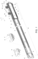
FIG. 1 is a schematic diagram of a slide rail mechanism according to an embodiment of the present invention, -
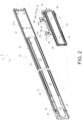
FIG. 2 is an exploded diagram of the slide rail mechanism according to the embodiment of the present invention, -
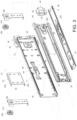
FIG. 3 is an exploded diagram of a slide rail assembly of the slide rail mechanism according to the embodiment of the present invention, -
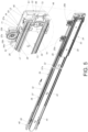
FIG. 4 is a diagram of the slide rail mechanism as the slide rail assembly is in a retracted state according to the embodiment of the present invention, -
FIG. 5 is a diagram of the slide rail mechanism as a second rail and a first rail of the slide rail assembly are synchronously displaceable along a first predetermined direction according to the embodiment of the present invention, -
FIG. 6 is a diagram of the slide rail mechanism as displacement synchronization between the second rail and the first rail of the slide rail assembly is terminated according to the embodiment of the present invention, -
FIG. 7 is a diagram of the slide rail mechanism as a third rail and the second rail of the slide rail assembly are not synchronously displaceable along the first predetermined direction according to the embodiment of the present invention, -
FIG. 8 is a diagram of the slide rail mechanism as the third rail and the second rail of the slide rail assembly are synchronously displaceable along the first predetermined direction according to the embodiment of the present invention -
FIG.9 is a diagram of the slide rail mechanism as displacement synchronization between the third rail and the second rail of the slide rail assembly is terminated according to the embodiment of the present invention, -
FIG. 10 is a diagram of the slide rail mechanism as the second rail of the slide rail assembly is located at a third predetermined position according to the embodiment of the present invention, -
FIG. 11 is a diagram of the slide rail mechanism as the slide rail assembly is in an extended state according to the embodiment of the present invention, -
FIG. 12 is a diagram of the slide rail mechanism as the third rail of the slide rail assembly displaces away from a fourth predetermined position along a second predetermined direction according to the embodiment of the present invention, -
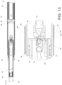
FIG. 13 is a diagram of the slide rail mechanism as the second rail of the slide rail assembly is displaceable away from the third predetermined position along the second predetermined direction by the third rail displacing along the second predetermined direction according to the embodiment of the present invention, -
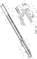
FIG. 14 is a diagram of the slide rail mechanism as the second rail of the slide rail assembly displaces away from the third predetermined position as shown inFIG. 13 along the second predetermined direction according to the embodiment of the present invention -
FIG. 15 is a diagram of the slide rail mechanism as the first rail of the slide rail assembly is displaceable away from the second predetermined position along the second predetermined direction by the second rail displacing along the second predetermined direction according to the embodiment of the present invention, and -
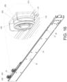
FIG. 16 is a diagram illustrating that at least one rolling member and a first supporting member of the slide rail mechanism respectively have cooperating features configured to cooperate with each other according to the embodiment of the present invention. - In the following detailed description of the preferred embodiments, reference is made to the accompanying drawings which form a part hereof, and in which is shown by way of illustration specific embodiments in which the invention may be practiced. In this regard, directional terminology, such as "top", "bottom", "left", "right", "front", "back", etc., is used with reference to the orientation of the Figure(s) being described. The members of the present invention can be positioned in a number of different orientations. As such, the directional terminology is used for purposes of illustration and is in no way limiting. Accordingly, the drawings and descriptions will be regarded as illustrative in nature and not as restrictive. Also, if not specified, the term "connect" is intended to mean either an indirect or direct mechanical connection. Thus, if a first device is connected to a second device, that connection may be through a direct mechanical connection, or through an indirect mechanical connection via other devices and connections.
- As shown in
FIG. 1 to FIG. 3 , a slide rail mechanism includes a first supportingmember 22, aslide rail assembly 24 and at least one rolling member. A length M1 of theslide rail assembly 24 along a longitudinal direction is different from a length M2 of the first supportingmember 22 along the longitudinal direction. For example, as shown inFIG. 1 , the length M1 of theslide rail assembly 24 along the longitudinal direction can be less than the length M2 of the first supportingmember 22. Furthermore, theslide rail assembly 24 includes afirst rail 26. A length of thefirst rail 26 along the longitudinal direction is less than the length M2 of the first supportingmember 22 along the longitudinal direction. Besides, the slide rail mechanism further includes a second supportingmember 34 connected to the first supportingmember 22, and the length of thefirst rail 26 along the longitudinal direction is less than a length of the second supportingmember 34 along the longitudinal direction. Thefirst rail 26 and the first supportingmember 22 are displaceable relative to each other. In this embodiment, by way of example, the longitudinal direction can be defined by a length direction or a displacing direction of a slide rail, e.g., thefirst rail 26, and parallel to an X axis. A transverse direction can be defined by a lateral direction or a width direction of the slide rail, e.g., thefirst rail 26, and parallel to a Y axis. A vertical direction can be defined by a height direction of the slide rail, e.g., thefirst rail 26, and parallel to a Z axis. The second supportingmember 34 can be a supporting frame configured to enable the first supportingmember 22 and theslide rail assembly 24 to be mounted on a rack. - In this embodiment, by way of example, the at least one rolling member can include a first rolling
member 25a, e.g., a front rolling member, and a second rollingmember 25b, e.g., a rear rolling member. The first rollingmember 25a and the second rollingmember 25b are configured to facilitate thefirst rail 26 and the first supportingmember 22 to be displaceable relative to each other. However, the present invention is not limited to this embodiment. For example, in another embodiment, the slide rail mechanism can include only one rolling member. - Preferably, the first rolling
member 25a and the second rollingmember 25b are arranged on one of thefirst rail 26 and the first supportingmember 22 and rotatably contacting with the other one of thefirst rail 26 and the first supportingmember 22. In this embodiment, by way of example, the first rollingmember 25a and the second rollingmember 25b can be arranged on thefirst rail 26 and spaced from each other at a distance along the longitudinal direction. Furthermore, the first rollingmember 25a is pivotally connected to a first mountingmember 29a by afirst shaft 27a, and the second rollingmember 25b is pivotally connected to a second mountingmember 29b by asecond shaft 27b. In this embodiment, by way of example, each of the first mountingmember 29a and the second mountingmember 29b can be fixedly connected to thefirst rail 26 and therefore regarded as a part of thefirst rail 26. Understandably, in another embodiment, the first mounting member and the second mounting member can be detachably connected to the first rail. - Preferably, the slide rail mechanism further includes a
slide rail device 32. Theslide rail device 32 includes the first supportingmember 22 and the second supportingmember 34. In this embodiment, by way of example, the first supportingmember 22 and the second supportingmember 34 can be fixedly connected to each other and therefore regarded as an integral structure. However, the present invention is not limited to this embodiment. The first rollingmember 25a and the second rollingmember 25b are displaceable together with thefirs rail 26. Furthermore, thefirst rail 26 is displaceable relative to the first supportingmember 22 along the longitudinal direction by the first rollingmember 25a and the second rollingmember 25b. The configuration of the first rollingmember 25a and the second rollingmember 25b can reduce a friction force resisting a displacement of thefirst rail 26 relative to the first supportingmember 22 for ensuring thefirst rail 26 to displace relative to the first supportingmember 22 smoothly. - Preferably, the first rolling
member 25a and the second rollingmember 25b can be members with arc-shaped contours, e.g., rollers or balls. However, the present invention is not limited thereto. - The
slide rail assembly 24 further includes asecond rail 28 and athird rail 30. In this embodiment, by way of example, thefirst rail 26, thesecond rail 28 and thethird rail 30 can be an outer rail, a middle rail and an inner rail, and thesecond rail 28 can be movably mounted between thefirst rail 26 and thethird rail 30. - Preferably, the second supporting
member 34 includes a disengagingfeature 36 and a blockingfeature 37 located adjacent to the disengagingfeature 36. In this embodiment, by way of example, the disengagingfeature 36 can be formed by excavating, and the blockingfeature 37 can be a wall. However, the present invention is not limited to this embodiment. - Preferably, a blocking
portion 38 is arranged on the first supportingmember 22. In this embodiment, by way of example, the first supportingmember 22 can include abracket 40 located adjacent to an end portion, e.g., a front end portion, of the first supportingmember 22, and the blockingportion 38 can be arranged on thebracket 40. - Preferably, the first supporting
member 22 further includes a supporting channel configured to at least partially receive a plurality of movable rails, e.g., a firstmovable rail 42 and a secondmovable rail 44. The firstmovable rail 42 is located between the first supportingmember 22 and the secondmovable rail 44. A length of thethird rail 30 of theslide rail assembly 24 along the longitudinal direction is less than a length of the secondmovable rail 44 of theslide rail device 32 along the longitudinal direction. It should be noticed that thethird rail 30 of theslide rail assembly 24 is configured to support a first object, which is not shown in the figures, and the secondmovable rail 44 of theslide rail device 32 is configured to support a second object, which is not shown in the figures. After the second object is detached from the secondmovable rail 44, or after the secondmovable rail 44 and the second object are together detached from the firstmovable rail 42, thefirst rail 26 of theslide rail assembly 24 can displace relative to the first supportingmember 22 and/or the second supportingmember 34 of theslide rail device 32 along the longitudinal direction by the first rollingmember 25a and the second rollingmember 25b. During a displacement of thefirst rail 26 or theslide rail assembly 24 relative to the first supportingmember 22 or theslide rail device 32 along the longitudinal direction, the configuration of the first rollingmember 25a and the second rollingmember 25b can reduce a friction force resisting the displacement of thefirst rail 26 or theslide rail assembly 24 relative to the first supportingmember 22 or theslide rail device 32 along the longitudinal direction. Therefore, the present invention can achieve an effect of saving effort. - Preferably, the
slide rail assembly 24 further includes a firstauxiliary member 46 and a secondauxiliary member 48. The firstauxiliary member 46 is arranged on thefirst rail 26. The secondauxiliary member 48 is arranged on thesecond rail 28. - Preferably, one of the first
auxiliary member 46 and the secondauxiliary member 48 is movable. The other one of the firstauxiliary member 46 and the secondauxiliary member 48 is immovable. In this embodiment, by way of example, the firstauxiliary member 46 can be pivotally connected to thefirst rail 26 by ashaft 50, so as to be pivotable relative to thefirst rail 26. The secondauxiliary member 48 can be fixedly connected to thesecond rail 28. - Preferably, the
slide rail assembly 24 further includes anauxiliary rail 52 arranged on thefirst rail 26. Thefirst rail 26 is movably mounted on one of the first supportingmember 22 and the second supportingmember 34 by theauxiliary rail 52. Furthermore, theauxiliary rail 52 includes a firstauxiliary wall 54a, a secondauxiliary wall 54b and amiddle wall 56 connected between the firstauxiliary wall 54a and the secondauxiliary wall 54b. Themiddle wall 56 is connected to a first side L1 of thefirst rail 26. As shown inFIG. 3 , in this embodiment, by way of example, themiddle wall 56 can be fixedly connected to the first side L1 of thefirst rail 26, and the first side L1 of thefirst rail 26 can be a back side of thefirst rail 26 located adjacent to the first supportingmember 22 or the second supportingmember 34. The firstauxiliary wall 54a and the secondauxiliary wall 54b are configured to hold the first supportingmember 22 or the second supportingmember 34. In this embodiment, by way of example, the firstauxiliary wall 54a and the secondauxiliary wall 54b can hold afirst wall 57a and asecond wall 57b of the first supportingmember 22 respectively, and thefirst wall 57a and thesecond wall 57b of the first supportingmember 22 can be an upper wall and a lower wall of the first supportingmember 22 respectively. However, the present invention is not limited to this embodiment. In addition, as shown inFIG. 3 , thesecond rail 28 is at least partially movably mounted inside a first channel of thefirst rail 26 formed on a second side L2 of thefirst rail 26 opposite to the first side L1 of thefirst rail 26. Besides, thethird rail 30 is at least partially movably mounted inside a second channel of thesecond rail 28. - Preferably, as shown in
FIG. 3 , theslide rail assembly 24 further includes a workingmember 58 movably mounted on thesecond rail 28. Acorresponding feature 60 is arranged on thethird rail 30 and configured to cooperate with the workingmember 58. Thethird rail 30 can drive thesecond rail 28 to synchronously displace together with thethird rail 30 by an abutment of thecorresponding feature 60 and the workingmember 58. - Preferably, the working
member 58 is pivotally connected to thesecond rail 28 by a connectingmember 62. - Preferably, a retaining
member 64 is arranged on thefirst rail 26. In this embodiment, by way of example, the retainingmember 64 can be a resilient element, such as a resilient plate. However, the present invention is not limited to this embodiment. The retainingmember 64 includes a disengagingstructure 66 and a blockingstructure 68 located adjacent to the disengagingstructure 66. In this embodiment, by way of example, the disengagingstructure 66 can be an inclined surface or an arc surface, and the blockingstructure 68 can be a wall, such as a vertical wall. However, the present invention is not limited to this embodiment. Understandably, in another embodiment, the disengaging structure and/or the blocking structure can be integrally connected to the first rail. - As shown in
FIG. 4 andFIG. 5 , theslide rail assembly 24 is in a retracted state relative to the first supportingmember 22 or theslide rail device 32. As shown inFIG. 5 , the secondauxiliary member 48 can abut against the firstauxiliary member 46 for driving thefirst rail 26 to displace together with thesecond rail 28 during a displacement of thesecond rail 28 away from a first predetermined position P1 along a firstpredetermined direction D 1. Besides, thesecond rail 28 can be driven by thethird rail 30 to synchronously displace together with thethird rail 30 by an abutment of thecorresponding feature 60 and the workingmember 58 during a displacement of thethird rail 30 along the first predetermined direction D1. Therefore, when thethird rail 30 is operated to displace along the first predetermined direction D1, thesecond rail 28 can synchronously displace together with thethird rail 30 and thefirst rail 26 can synchronously displace together with thesecond rail 28, i.e., thethird rail 30, thesecond rail 28 and thefirst rail 26 can synchronously displace together along the first predetermined direction D1. During a displacement of thefirst rail 26 along the first predetermined direction D1, thefirst rail 26 engages with thefirst wall 57a of the first supportingmember 22 via the first rollingmember 25a and the second rollingmember 25b, and the configuration of the first rollingmember 25a and the second rollingmember 25b can reduce the friction force resisting the displacement of thefirst rail 26 relative to the first supportingmember 22 along the first predetermined direction D1 by rotating movements of the first rollingmember 25a and the second rollingmember 25b relative to thefirst wall 57a, e.g., the upper wall, of the first supportingmember 22. Besides, thefirst wall 57a, e.g., the upper wall, of the first supportingmember 22 can support the first rollingmember 25a and the second rollingmember 25b for enhancing a supporting strength of thefirst rail 26 or theslide rail assembly 24. Preferably, since the firstauxiliary wall 54a and the secondauxiliary wall 54b of theauxiliary rail 52 hold thefirst wall 57a and thesecond wall 57b respectively, it facilitates stability and reliability of the displacement of thefirst rail 26 relative to the first supportingmember 22 along the firstpredetermined direction D 1. - Preferably, as shown in
FIG. 5 , theslide rail assembly 24 further includes aresilient member 70. The firstauxiliary member 46 is retained in a first state S1 for abutting against the secondauxiliary member 48 in response to a resilient force provided by theresilient member 70 and/or a support of the second supportingmember 34. As shown inFIG. 4 andFIG. 5 , in this embodiment, by way of example, the secondauxiliary member 48 can include at least one abuttingportion 72, such as a hook portion or a hook-shaped structure, configured to abut against a correspondingportion 69 of the firstauxiliary member 46 for driving thefirst rail 26 to synchronously displace together with thesecond rail 28 during the displacement of thesecond rail 28 away from the first predetermined position P1 along the first predetermined direction D1. - Preferably, the
resilient member 70 is arranged on the first side L1 of thefirst rail 26 and hidden between thefirst rail 26 and the first supportingmember 22 or between thefirst rail 26 and theslide rail device 32. In this embodiment, by way of example, theresilient member 70 can be a resilient plate. However, the present invention is not limited to this embodiment. As shown inFIG. 5 , theresilient member 70 includes at least oneresilient portion 71 for providing the resilient force to at least one extendingportion 73 of the firstauxiliary member 46, and the second supportingmember 34 supports the firstauxiliary member 46, such that the firstauxiliary member 46 is retained in the first state S1. - As shown in
FIG. 6 , the disengagingfeature 36 of the second supportingmember 34 is configured to terminate displacement synchronization between thesecond rail 28 and thefirst rail 26 when thesecond rail 28 and thefirst rail 26 are synchronously displaced to a second predetermined position P2 along the firstpredetermined direction D 1. - Preferably, when the
first rail 26 is located at the second predetermined position P2, the disengagingfeature 36 of the second supportingmember 34 is configured to provide a moving space for the firstauxiliary member 46, so as to release theresilient member 70 to drive the firstauxiliary member 46 to move, e.g., pivot along a predetermined pivoting direction R, from the first state S1 to a second state S2 for disengaging the firstauxiliary member 46 from the secondauxiliary member 48, such that the correspondingportion 69 of the firstauxiliary member 46 can be moved to be misaligned with the at least one abuttingportion 72 of the secondauxiliary member 48 along the longitudinal direction, e.g., the X axis, so as to terminate the displacement synchronization between thesecond rail 28 and thefirst rail 26. - Preferably, when the first
auxiliary member 46 is in the second state S2, the blockingfeature 37 of the second supportingmember 34 can block the firstauxiliary member 46 for preventing thefirst rail 26 from displacing away from the second predetermined position P2 along a second predetermined direction D2, e.g., a retracting direction, opposite to the first predetermined direction D1. Moreover, the blockingportion 38 on the first supportingmember 22 can block one of thefirst rail 26 and theauxiliary rail 52 for preventing thefirst rail 26 from displacing away from the second predetermined position P2 along the first predetermined direction D1. In this embodiment, by way of example, the blockingportion 38 arranged on thebracket 40 of the first supportingmember 22 can block the first mountingmember 29a of thefirst rail 26. However, the present invention is not limited to this embodiment. -
FIG. 7 to FIG. 13 does not illustrate the first rollingmember 25a, the second rollingmember 25b, the first mountingmember 29a and the second mountingmember 29b for simplicity. As shown inFIG. 7 andFIG. 8 , theslide rail assembly 24 further includes at least one first slide-aidingdevice 74 and a second slide-aidingdevice 76. The at least one first slide-aidingdevice 74 is movably mounted between thesecond rail 28 and thefirst rail 26 for facilitating a smooth displacement of thesecond rail 28 relative to thefirst rail 26. The second slide-aidingdevice 76 is movably mounted between thesecond rail 28 and thethird rail 30 for facilitating a smooth displacement of thethird rail 30 relative to thesecond rail 28. In this embodiment, by way of example, the first slide-aidingdevice 74 can include a plurality of first slide-aidingmembers 78, and the second slide-aidingdevice 76 can include a plurality of second slide-aidingmembers 80, wherein the first slide-aidingmember 78 or the second slide-aidingmember 80 can be a ball, a roller, or the like. - In detail, during a displacement of the
second rail 28 from the first predetermined position P1 to the second predetermined position P2, if thethird rail 30 does not displace relative to thesecond rail 28 along the first predetermined direction D1, thecorresponding feature 60 on the third rail and the workingmember 58 on thesecond rail 28 are spaced from each other at a predetermined distance along the longitudinal direction. Preferably, during the displacement of thethird rail 30 along the first predetermined direction D1, thethird rail 30 drives thesecond rail 28 to displace along the first predetermined direction D1 by a frictional force therebetween as shown inFIG. 7 before the abutment of thecorresponding feature 60 and the workingmember 58, and then thethird rail 30 drives thesecond rail 28 to synchronously displace together with thethird rail 30 by the abutment of thecorresponding feature 60 and the workingmember 58 as shown inFIG. 8 after the abutment of thecorresponding feature 60 and the workingmember 58. - Preferably, the
third rail 30 includes afirst wall 82a and asecond wall 82b, and thecorresponding feature 60 is arranged on thefirst wall 82a of thethird rail 30. For example, thecorresponding feature 60 can be a hole wall of a hole H. Thefirst wall 82a of thethird rail 30 can support the workingmember 58 for retaining the workingmember 58 in an initial state K1 as shown inFIG. 7 . During the displacement of thethird rail 30 along the first predetermined direction D1, the hole H formed on thethird rail 30 moves to a position corresponding to asynchronization feature 84 of the workingmember 58 for allowing the workingmember 58 to move, e.g., pivot, from the initial state K1 to a predetermined position K2 as shown inFIG .8 in response to a resilient force provided by aresilient object 86, such that thecorresponding feature 60 on thethird rail 30 abuts against thesynchronization feature 84 of the workingmember 58 to enable thethird rail 30 to drive thesecond rail 28 to synchronously displace together with thethird rail 30 as shown inFIG. 8 . - Preferably, as shown in
FIG. 8 , thesecond rail 28 includes a throughhole 88, and a workingportion 90 of the workingmember 58 extends toward thefirst rail 26 through the throughhole 88. The workingportion 90 of the workingmember 58 can cooperate with the retainingmember 64, e.g., the disengagingstructure 66 and the blockingstructure 68 of the retainingmember 64, on thefirst rail 26. - When the
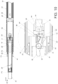
third rail 30 drives thesecond rail 28 to synchronously displace together with thethird rail 30 from a position as shown inFIG. 8 to a disengaging position as shown inFIG. 9 , the disengagingstructure 66 on thefirst rail 26 is configured to terminate displacement synchronization between thethird rail 30 and thesecond rail 28. In this embodiment, by way of example, the workingportion 90 of the workingmember 58 on thesecond rail 28 can be guided by the disengagingstructure 66 on thefirst rail 26 to drive the workingmember 58 to move away from the predetermined state K2, e.g., by pivoting at a predetermined angle, such that thecorresponding feature 60 on thethird rail 30 does not abut against thesynchronization feature 84 of the workingmember 58 for terminating the synchronization displacement between thethird rail 30 and thesecond rail 28. After the synchronization displacement between thethird rail 30 and thesecond rail 28 is terminated, thethird rail 30 and thesecond rail 28 can be individually displaced relative to thefirst rail 26 along the first predetermined direction D1. Besides, when the workingmember 58 is in a state as shown inFIG. 9 , theresilient object 86 is resiliently deformed. - As shown in
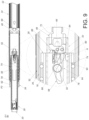
FIG. 10 , when thesecond rail 28 is further displaced to a third predetermined position P3 along the first predetermined direction D1, the blockingstructure 68 on thefirst rail 26 is configured to block thesecond rail 28 for preventing thesecond rail 28 from displacing away from the third predetermined position P3 along the second predetermined direction D2. In this embodiment, by way of example, when thesecond rail 28 is located at the third predetermined position P3, theresilient object 86 can be released to drive the workingmember 58 to move to a position as shown inFIG. 10 , such that the workingportion 90 of the workingmember 58 can be blocked by the blockingstructure 68 on thefirst rail 26 for preventing thesecond rail 28 from displacing away from the third predetermined position P3 along the second predetermined direction D2. - Preferably, a
first restraining feature 92 is further arranged on thefirst rail 26, and asecond restraining feature 94 is further arranged on thesecond rail 28. When thesecond rail 28 is located at the third predetermined position P3, a front end and a rear end of the first slide-aidingdevice 74 abut against thefirst restraining feature 92 and thesecond restraining feature 94 respectively for preventing thesecond rail 28 from displacing away from the third predetermined position P3 along the first predetermined direction D1. - As shown in
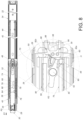
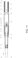
FIG. 11 , when thesecond rail 28 is located at the third predetermined position P3, thethird rail 30 can be further displaced to a fourth predetermined position P4 along the first predetermined direction D1, so as to locate theslide rail assembly 24 in an extended state, e.g., a fully extended state, relative to the first supportingmember 22 or theslide rail device 32. Preferably, when thethird rail 30 is located at the fourth predetermined position P4, the second slide-aidingdevice 76 is located adjacent to an end portion, e.g., a front end portion, of thesecond rail 28. - As shown in
FIG. 12 andFIG. 13 , during a displacement of thethird rail 30 away from the fourth predetermined position P4 along the second predetermined direction D2, thethird rail 30 is configured to terminate a blocking relation between the blockingstructure 68 and thesecond rail 28. Furthermore, as shown inFIG. 12 andFIG. 13 , a portion, e.g., a rear end portion r, of thethird rail 30, is configured to abut against thesynchronization feature 84 of the workingmember 58 for driving the workingmember 58 to prevent the workingportion 90 of the workingmember 58 from being blocked by the blockingstructure 68 on thefirst rail 26. When the workingportion 90 of the workingmember 58 is not blocked by the blockingstructure 68 on thefirst rail 26, thesecond rail 28 is allowed to displace away from the third predetermined position P3 along the second predetermined direction D2. - As shown in
FIG. 14 andFIG. 15 , one of thesecond rail 28 and the firstauxiliary member 46 includes afirst guiding feature 96. Preferably, the other one of thesecond rail 28 and the firstauxiliary member 46 includes asecond guiding feature 98 for cooperating with thefirst guiding feature 96. As shown inFIG. 3 , in this embodiment, by way of example, thesecond rail 28 can include thefirst guiding feature 96 arranged on the secondauxiliary member 48, and the firstauxiliary member 46 can include thesecond guiding feature 98, wherein thefirst guiding feature 96 and thesecond guiding feature 98 can be inclined surfaces or arc surfaces. However, the present invention is not limited to this embodiment. - During a displacement of the
second rail 28 away from the third predetermined position P3 along the second predetermined direction D2, thesecond rail 28 is configured to terminate a blocking relation between the blockingfeature 37 and thefirst rail 26. In this embodiment, by way of example, thefirst guiding structure 96 of thesecond rail 28 can abut against thesecond guiding structure 98 of the firstauxiliary member 46 for driving the firstauxiliary member 46 from the second state S2 as shown inFIG. 14 to the first state S1 as shown inFIG. 15 , such that the blockingfeature 37 of the second supportingmember 34 does not block the firstauxiliary member 46 on thefirst rail 26 for allowing thefirst rail 26 and theauxiliary rail 52 to displace away from the second predetermined position P2 along the second predetermined direction D2. Accordingly, thethird rail 30, thesecond rail 28 and thefirst rail 26 can be displaced along the second predetermined direction D2 until theslide rail assembly 24 is moved back to the retracted state as shown inFIG. 4 . During a displacement of thefirst rail 26 or theslide rail assembly 24 relative to the first supportingmember 22 or theslide rail device 32 along the second predetermined direction D2, the configuration of the first rollingmember 25a and the second rollingmember 25b can reduce a friction force resisting the displacement of thefirst rail 26 or theslide rail assembly 24 relative to the first supportingmember 22 or theslide rail device 32 along the second predetermined direction D2 by the rotating movements of the first rollingmember 25a and the second rollingmember 25b relative to thefirst wall 57a, e.g., the upper wall, of the first supportingmember 22. Besides, thefirst wall 57a, e.g., the upper wall, of the first supportingmember 22 can support the first rollingmember 25a and the second rollingmember 25b for enhancing the supporting strength of thefirst rail 26 or theslide rail assembly 24. - It should be noticed that the
slide rail assembly 24 can be adapted for the rack, and thethird rail 30 can be configured to support the first object, such as an electronic apparatus or a drawer. Theslide rail assembly 24 can ensure thesecond rail 28 and thefirst rail 26 to displace synchronously and prevent thethird rail 30 and thesecond rail 28 from being pulled out along the first predetermined direction D1 without any displacement of thefirst rail 26. Therefore, theslide rail assembly 24 can solve a technical problem that it takes a lot of effort to overcome an excessive friction between a first rail and a supporting frame and/or between the first rail and a supporting rail caused by, e.g., a weight of a carried object, to pull out the first rail if a third rail and a second rail have been pulled out without any displacement of the first rail. Besides, the configuration of the first rollingmember 25a and the second rollingmember 25b can reduce the friction forces resisting the displacements of thefirst rail 26 or theslide rail assembly 24 relative to the first supportingmember 22 or theslide rail device 32 along the first predetermined direction D1 and the second predetermined direction D2 by the rotating movements of the first rollingmember 25a and the second rollingmember 25b relative to thefirst wall 57a, e.g., the upper wall, of the first supportingmember 22. - As shown in
FIG. 16 , the first supportingmember 22 and each of the first rollingmember 25a and the second rollingmember 25b have two cooperating features configured to cooperate with each other. Furthermore, one of the first supportingmember 22 and each of the first rollingmember 25a and the second rollingmember 25b includes a first cooperatingfeature 100, and the other one of the first supportingmember 22 and each of the first rollingmember 25a and the second rollingmember 25b includes a second cooperatingfeature 102 configured to cooperate with the first cooperatingfeature 100. In this embodiment, by way of example, each of the first rollingmember 25a and the second rollingmember 25b can include the first cooperatingfeature 100, and the first supportingmember 22 can include the second cooperatingfeature 102. - Specifically, the first cooperating
feature 100 can be a groove structure, and the second cooperatingfeature 102 can be a protruding edge extending along the longitudinal direction configured to abut against the groove structure for enhancing stability and reliability of the rotating movements of the first rollingmember 25a and the second rollingmember 25b relative to thefirst wall 57a of the first supportingmember 22 along the longitudinal direction. - From the above, the
slide rail assembly 24 includes the following characteristics. - 1. The configuration of at least one rolling member, e.g., the first rolling
member 25a and/or the second rollingmember 25b, arranged on thefirst rail 26 of theslide rail assembly 24 can reduce the friction forces resisting the displacements of thefirst rail 26 or theslide rail assembly 24 relative to the first supportingmember 22 along the first predetermined direction D1 and the second predetermined direction D2. - 2. The
second rail 28 can synchronously displace together with thefirst rail 26 along the first predetermined direction D1, and/or thethird rail 30 can synchronously displace together with thesecond rail 28 along the firstpredetermined direction D 1. - 3. The at least one rolling member, e.g., the first rolling
member 25a and/or the second rollingmember 25b, and the first supportingmember 22 respectively include the first cooperatingfeature 100 and the second cooperatingfeature 102 configured to cooperate with the first cooperatingfeature 100 for enhancing stability and reliability of the rotating movements of the first rollingmember 25a and the second rollingmember 25b relative to the first supportingmember 22 along the longitudinal direction. - Those skilled in the art will readily observe that numerous modifications and alterations of the device and method may be made while retaining the teachings of the invention. Accordingly, the above disclosure should be construed as limited only by the metes and bounds of the appended claims.
Claims (15)
- A slide rail mechanism characterized by:a first supporting member (22);a slide rail assembly (24), a length (M1) of the slide rail assembly (24) being different from a length (M2) of the first supporting member (22), and the slide rail assembly (24) comprising a first rail (26); andat least one rolling member (25a, 25b), the first rail (26) and the first supporting member (22) being displaceable relative to each other by the at least one rolling member (25a, 25b).
- The slide rail mechanism of claim 1, characterized in that the at least one rolling member (25a, 25b) is arranged on one of the first rail (26) and the first supporting member (22) and rotatably contacting with another one of the first rail (26) and the first supporting member (22).
- The slide rail mechanism of any one of claims 1 and 2, characterized in that a length of the first rail (26) along a longitudinal direction is less than the length (M2) of the first supporting member (22) along the longitudinal direction.
- The slide rail mechanism of any one of claims 1 to 3, characterized in the first supporting member (22) comprises a first wall (57a) and a second wall (57b), the first rail (26) is engaged with the first wall (57a) of the first supporting member (22) via the at least one rolling member (25a, 25b), the first wall (57a) and the second wall (57b) of the first supporting member (22) are an upper wall and a lower wall respectively, the at least one rolling member (25a, 25b) comprises a first cooperating feature (100), and the first supporting member (22) comprises a second cooperating feature (102) configured to cooperate with the first cooperating feature (100).
- The slide rail mechanism of any one of claims 1 to 4, further characterized by a second supporting member (34) connected to the first supporting member (22), the second supporting member (34) comprising a disengaging feature (36), the slide rail assembly (24) further comprising a second rail (28) and a third rail (30), the first rail (26) being an outer rail, the second rail (28) being a middle rail, and the third rail (30) being an inner rail, the second rail (28) and the first rail (26) displacing synchronously during a displacement of the second rail (28) away from a first predetermined position (P1) along a first predetermined direction (D1), and the disengaging feature (36) of the second supporting member (34) being configured to terminate a displacement synchronization between the second rail (28) and the first rail (26) when the second rail (28) and the first rail (26) are synchronously displaced to a second predetermined position (P2) along the first predetermined direction (D1).
- The slide rail mechanism of claim 5, characterized in that the slide rail assembly (24) further comprises a first auxiliary member (46) and a second auxiliary member (48), the first auxiliary member (46) is arranged on the first rail (26), the second auxiliary member (48) is arranged on the second rail (28), and the second rail (28) and the first rail (26) displace synchronously by an abutment of the first auxiliary member (46) and the second auxiliary member (48) during the displacement of the second rail (28) away from the first predetermined position (P1) along the first predetermined direction (D1).
- The slide rail mechanism of claim 6, characterized in that the slide rail assembly (24) further comprises a resilient member (70), one of the first auxiliary member (46) and the second auxiliary member (48) is movable, and the one of the first auxiliary member (46) and the second auxiliary member (48) is configured to move to a first state (S1) for abutting against another one of the first auxiliary member (46) and the second auxiliary member (48) in response to a resilient force provided by the resilient member (70).
- The slide rail mechanism of claim 7, characterized in that the disengaging feature (36) of the second supporting member (34) is configured to release the resilient member (70) to drive the one of the first auxiliary member (46) and the second auxiliary member (48) from the first state (S1) to a second state (S2) so as to disengage the one of the first auxiliary member (46) and the second auxiliary member (48) from the another one of the first auxiliary member (46) and the second auxiliary member (48) for terminating the displacement synchronization between the second rail (28) and the first rail (26) when the second rail (28) is displaced to the second predetermined position (P2), the disengaging feature (36) of the second supporting member (34) is formed by excavating and configured to provide a moving space for the one of the first auxiliary member (46) and the second auxiliary member (48).
- The slide rail mechanism of any one of claims 5 to 8, characterized in that the second supporting member (34) further comprises a blocking feature (37) located adjacent to the disengaging feature (36) and configured to block the first rail (26) for preventing the first rail (26) from displacing away from the second predetermined position (P2) along a second predetermined direction (D2)opposite to the first predetermined direction (D1), and the second rail (28) is configured to terminate a blocking relation between the blocking feature (37) and the first rail (26) during a displacement of the second rail (28) away from a third predetermined position (P3) along the second predetermined direction (D2).
- The slide rail mechanism of claim 9, characterized in that the slide rail assembly (24) further comprises a working member (58) movably mounted on the second rail (28), a corresponding feature (60) is arranged on the third rail (30), the third rail (30) drives the second rail (28) to synchronously displace together with the third rail (30) by an abutment of the corresponding feature (60) and the working member (58) during a displacement of the third rail (30) along the first predetermined direction (D1), the working member (58) is pivotally connected to the second rail (28) by a connecting member (62), and the working member (58) is driven to a predetermined state (K2) for abutting against the corresponding feature (60) in response to a resilient force provided by a resilient object (86).
- The slide rail mechanism of any one of claims 9 and 10, characterized in that a disengaging structure (66) is arranged on the first rail (26), the disengaging structure (66) is configured to terminate a displacement synchronization between the third rail (30) and the second rail (28) when the third rail (30) and the second rail (28) are synchronously displaced to a disengaging position along the first predetermined direction (D1), a blocking structure (68) is further arranged on the first rail (26) and located adjacent to the disengaging structure (66), the blocking structure (68) blocks the second rail (28) for preventing the second rail (28) from displacing away from the third predetermined position (P3) along the second predetermined direction (D2), the third rail (30) is displaceable to a fourth predetermined position along the first predetermined direction (D1) when the second rail (28) is displaced to the third predetermined position (P3) along the first predetermined direction (D1), and the third rail (30) is configured to terminate a blocking relation between the blocking structure (68) and the second rail (28) during a displacement of the third rail (30) away from the fourth predetermined position along the second predetermined direction (D2).
- The slide rail mechanism of any one of claims 5 to 8, characterized in that a disengaging structure (66) is arranged on the first rail (26), the disengaging structure (66) is configured to terminate a displacement synchronization between the third rail (30) and the second rail (28) when the third rail (30) and the second rail (28) are synchronously displaced to a disengaging position along the first predetermined direction (D1).
- The slide rail mechanism of claim 12, characterized in that a blocking structure (68) is further arranged on the first rail (26) and located adjacent to the disengaging structure (66), the blocking structure (68) blocks the second rail (28) for preventing the second rail (28) from displacing away from a third predetermined position (P3) along a second predetermined direction (D2) opposite to the first predetermined direction (D1) and the third rail (30) is displaceable to a fourth predetermined position along the first predetermined direction (D1) when the second rail (28) is displaced to the third predetermined position (P3) along the first predetermined direction (D1), and the third rail (30) is configured to terminate a blocking relation between the blocking structure (68) and the second rail (28) during a displacement of the third rail (30) away from the fourth predetermined position along the second predetermined direction (D2).
- The slide rail mechanism of claim 13, characterized in that the second supporting member (34) further comprises a blocking feature (37) located adjacent to the disengaging feature (36) and configured to block the first rail (26) for preventing the first rail (26) from displacing away from the second predetermined position (P2) along the second predetermined direction (D2), and the second rail (28) is configured to terminate a blocking relation between the blocking feature (37) and the first rail (26) during a displacement of the second rail (28) away from the third predetermined position (P3) along the second predetermined direction (D2).
- The slide rail mechanism of any one of claims 5 to 8 and 12 to 14, characterized in that the slide rail assembly (24) further comprises a working member (58) movably mounted on the second rail (28), a corresponding feature (60) is arranged on the third rail (30), the third rail (30) drives the second rail (28) to synchronously displace together with the third rail (30) by an abutment of the corresponding feature (60) and the working member (58) during a displacement of the third rail (30) along the first predetermined direction (D1), the working member (58) is pivotally connected to the second rail (28) by a connecting member (62), and the working member (58) is driven to a predetermined state (K2) for abutting against the corresponding feature (60) in response to a resilient force provided by a resilient object (86).
Applications Claiming Priority (1)
| Application Number | Priority Date | Filing Date | Title |
|---|---|---|---|
| TW112125380A TWI829606B (en) | 2023-07-05 | 2023-07-05 | Slide rail mechanism |
Publications (2)
| Publication Number | Publication Date |
|---|---|
| EP4489537A1 true EP4489537A1 (en) | 2025-01-08 |
| EP4489537B1 EP4489537B1 (en) | 2025-10-01 |
Family
ID=88600353
Family Applications (1)
| Application Number | Title | Priority Date | Filing Date |
|---|---|---|---|
| EP23206662.1A Active EP4489537B1 (en) | 2023-07-05 | 2023-10-30 | Slide rail mechanism |
Country Status (4)
| Country | Link |
|---|---|
| US (1) | US12390009B2 (en) |
| EP (1) | EP4489537B1 (en) |
| JP (1) | JP7816693B2 (en) |
| TW (1) | TWI829606B (en) |
Cited By (1)
| Publication number | Priority date | Publication date | Assignee | Title |
|---|---|---|---|---|
| EP4616761A1 (en) * | 2024-03-12 | 2025-09-17 | King Slide Works Co., Ltd. | Slide rail mechanism |
Families Citing this family (1)
| Publication number | Priority date | Publication date | Assignee | Title |
|---|---|---|---|---|
| CN115648173A (en) * | 2022-11-01 | 2023-01-31 | 北京凯祥弘康生物科技有限公司 | A mechanical arm track running device |
Citations (2)
| Publication number | Priority date | Publication date | Assignee | Title |
|---|---|---|---|---|
| US8147011B2 (en) | 2009-12-04 | 2012-04-03 | King Slide Works Co., Ltd. | Slide assembly |
| US20200337462A1 (en) * | 2019-04-23 | 2020-10-29 | King Slide Works Co., Ltd. | Slide rail assembly |
Family Cites Families (8)
| Publication number | Priority date | Publication date | Assignee | Title |
|---|---|---|---|---|
| US6257683B1 (en) * | 2000-03-13 | 2001-07-10 | Jun-Long Yang | Detachable rail for a drawer track |
| US7118277B2 (en) * | 2004-12-08 | 2006-10-10 | King Slide Works Co., Ltd. | Slide assembly |
| JP2013255678A (en) | 2012-06-13 | 2013-12-26 | Ricoh Co Ltd | Slide rail, sheet feed device, and image forming apparatus |
| TWI693042B (en) * | 2018-07-19 | 2020-05-11 | 川湖科技股份有限公司 | Slide rail mechanism and bracket device thereof |
| TWI676440B (en) * | 2018-11-29 | 2019-11-11 | 川湖科技股份有限公司 | Slide rail assembly |
| US11583078B2 (en) * | 2020-08-04 | 2023-02-21 | Accuride International, Inc. | Extendable drawer slide |
| TWI763536B (en) | 2021-06-09 | 2022-05-01 | 川湖科技股份有限公司 | Slide rail assembly |
| TWI760286B (en) | 2021-09-29 | 2022-04-01 | 川湖科技股份有限公司 | Slide rail assembly |
-
2023
- 2023-07-05 TW TW112125380A patent/TWI829606B/en active
- 2023-10-19 US US18/382,052 patent/US12390009B2/en active Active
- 2023-10-30 EP EP23206662.1A patent/EP4489537B1/en active Active
- 2023-11-09 JP JP2023191835A patent/JP7816693B2/en active Active
Patent Citations (2)
| Publication number | Priority date | Publication date | Assignee | Title |
|---|---|---|---|---|
| US8147011B2 (en) | 2009-12-04 | 2012-04-03 | King Slide Works Co., Ltd. | Slide assembly |
| US20200337462A1 (en) * | 2019-04-23 | 2020-10-29 | King Slide Works Co., Ltd. | Slide rail assembly |
Cited By (1)
| Publication number | Priority date | Publication date | Assignee | Title |
|---|---|---|---|---|
| EP4616761A1 (en) * | 2024-03-12 | 2025-09-17 | King Slide Works Co., Ltd. | Slide rail mechanism |
Also Published As
| Publication number | Publication date |
|---|---|
| JP7816693B2 (en) | 2026-02-18 |
| TWI829606B (en) | 2024-01-11 |
| US12390009B2 (en) | 2025-08-19 |
| JP2025009694A (en) | 2025-01-20 |
| EP4489537B1 (en) | 2025-10-01 |
| TW202502242A (en) | 2025-01-16 |
| US20250009127A1 (en) | 2025-01-09 |
Similar Documents
| Publication | Publication Date | Title |
|---|---|---|
| EP4489537B1 (en) | Slide rail mechanism | |
| EP3609304B1 (en) | Slide rail mechanism and bracket device thereof | |
| EP4741611A1 (en) | Slide rail mechanism | |
| EP4477823A1 (en) | Interlock kit and related furniture assembly | |
| EP4420560A1 (en) | Slide rail mechanism | |
| EP4417088A1 (en) | Slide rail mechanism | |
| EP4501174A1 (en) | Slide rail assembly | |
| EP4393349B1 (en) | Slide rail assembly | |
| CN214207535U (en) | Automatic lifting slide rail of extension table | |
| EP4631393A1 (en) | Slide rail assembly | |
| EP4461160A1 (en) | Furniture assembly | |
| EP4523567A1 (en) | Slide rail assembly | |
| EP4403732A1 (en) | Slide rail mechanism | |
| EP4456686A1 (en) | Slide rail assembly | |
| US12628950B2 (en) | Slide rail assembly | |
| EP4480344A1 (en) | Slide rail assembly | |
| EP4736711A1 (en) | Slide rail assembly | |
| EP4648558A1 (en) | Rack mounting kit | |
| EP4635366B1 (en) | Slide rail assembly | |
| CN223787334U (en) | A drawer slide device with fully synchronized function | |
| JP2654845B2 (en) | Shelf with slide table | |
| CN214684858U (en) | An automatic vertical welding equipment for steel arch automatic production line | |
| US20260132656A1 (en) | Slide rail mechanism | |
| CN222007207U (en) | Single-column lifter | |
| JPS637080Y2 (en) |
Legal Events
| Date | Code | Title | Description |
|---|---|---|---|
| PUAI | Public reference made under article 153(3) epc to a published international application that has entered the european phase |
Free format text: ORIGINAL CODE: 0009012 |
|
| STAA | Information on the status of an ep patent application or granted ep patent |
Free format text: STATUS: REQUEST FOR EXAMINATION WAS MADE |
|
| 17P | Request for examination filed |
Effective date: 20241030 |
|
| AK | Designated contracting states |
Kind code of ref document: A1 Designated state(s): AL AT BE BG CH CY CZ DE DK EE ES FI FR GB GR HR HU IE IS IT LI LT LU LV MC ME MK MT NL NO PL PT RO RS SE SI SK SM TR |
|
| GRAP | Despatch of communication of intention to grant a patent |
Free format text: ORIGINAL CODE: EPIDOSNIGR1 |
|
| STAA | Information on the status of an ep patent application or granted ep patent |
Free format text: STATUS: GRANT OF PATENT IS INTENDED |
|
| RIC1 | Information provided on ipc code assigned before grant |
Ipc: A47B 88/493 20170101ALI20250415BHEP Ipc: A47B 88/443 20170101ALI20250415BHEP Ipc: H05K 7/18 20060101AFI20250415BHEP |
|
| INTG | Intention to grant announced |
Effective date: 20250428 |
|
| GRAS | Grant fee paid |
Free format text: ORIGINAL CODE: EPIDOSNIGR3 |
|
| GRAA | (expected) grant |
Free format text: ORIGINAL CODE: 0009210 |
|
| STAA | Information on the status of an ep patent application or granted ep patent |
Free format text: STATUS: THE PATENT HAS BEEN GRANTED |
|
| AK | Designated contracting states |
Kind code of ref document: B1 Designated state(s): AL AT BE BG CH CY CZ DE DK EE ES FI FR GB GR HR HU IE IS IT LI LT LU LV MC ME MK MT NL NO PL PT RO RS SE SI SK SM TR |
|
| REG | Reference to a national code |
Ref country code: GB Ref legal event code: FG4D Ref country code: CH Ref legal event code: F10 Free format text: ST27 STATUS EVENT CODE: U-0-0-F10-F00 (AS PROVIDED BY THE NATIONAL OFFICE) Effective date: 20251001 |
|
| REG | Reference to a national code |
Ref country code: DE Ref legal event code: R096 Ref document number: 602023007125 Country of ref document: DE |
|
| REG | Reference to a national code |
Ref country code: IE Ref legal event code: FG4D |
|
| PGFP | Annual fee paid to national office [announced via postgrant information from national office to epo] |
Ref country code: DE Payment date: 20250925 Year of fee payment: 3 |
|
| PGFP | Annual fee paid to national office [announced via postgrant information from national office to epo] |
Ref country code: AT Payment date: 20260113 Year of fee payment: 3 |
|
| PGFP | Annual fee paid to national office [announced via postgrant information from national office to epo] |
Ref country code: IE Payment date: 20251121 Year of fee payment: 3 |
|
| REG | Reference to a national code |
Ref country code: NL Ref legal event code: MP Effective date: 20251001 |
|
| REG | Reference to a national code |
Ref country code: AT Ref legal event code: MK05 Ref document number: 1843994 Country of ref document: AT Kind code of ref document: T Effective date: 20251001 |
|
| PG25 | Lapsed in a contracting state [announced via postgrant information from national office to epo] |
Ref country code: NL Free format text: LAPSE BECAUSE OF FAILURE TO SUBMIT A TRANSLATION OF THE DESCRIPTION OR TO PAY THE FEE WITHIN THE PRESCRIBED TIME-LIMIT Effective date: 20251001 |
|
| PG25 | Lapsed in a contracting state [announced via postgrant information from national office to epo] |
Ref country code: ES Free format text: LAPSE BECAUSE OF FAILURE TO SUBMIT A TRANSLATION OF THE DESCRIPTION OR TO PAY THE FEE WITHIN THE PRESCRIBED TIME-LIMIT Effective date: 20251001 |
|
| REG | Reference to a national code |
Ref country code: LT Ref legal event code: MG9D |
|
| PG25 | Lapsed in a contracting state [announced via postgrant information from national office to epo] |
Ref country code: NO Free format text: LAPSE BECAUSE OF FAILURE TO SUBMIT A TRANSLATION OF THE DESCRIPTION OR TO PAY THE FEE WITHIN THE PRESCRIBED TIME-LIMIT Effective date: 20260101 |
|
| PG25 | Lapsed in a contracting state [announced via postgrant information from national office to epo] |
Ref country code: FI Free format text: LAPSE BECAUSE OF FAILURE TO SUBMIT A TRANSLATION OF THE DESCRIPTION OR TO PAY THE FEE WITHIN THE PRESCRIBED TIME-LIMIT Effective date: 20251001 Ref country code: AT Free format text: LAPSE BECAUSE OF FAILURE TO SUBMIT A TRANSLATION OF THE DESCRIPTION OR TO PAY THE FEE WITHIN THE PRESCRIBED TIME-LIMIT Effective date: 20251001 Ref country code: HR Free format text: LAPSE BECAUSE OF FAILURE TO SUBMIT A TRANSLATION OF THE DESCRIPTION OR TO PAY THE FEE WITHIN THE PRESCRIBED TIME-LIMIT Effective date: 20251001 |
|
| PG25 | Lapsed in a contracting state [announced via postgrant information from national office to epo] |
Ref country code: RS Free format text: LAPSE BECAUSE OF FAILURE TO SUBMIT A TRANSLATION OF THE DESCRIPTION OR TO PAY THE FEE WITHIN THE PRESCRIBED TIME-LIMIT Effective date: 20260101 |
|
| PG25 | Lapsed in a contracting state [announced via postgrant information from national office to epo] |
Ref country code: IS Free format text: LAPSE BECAUSE OF FAILURE TO SUBMIT A TRANSLATION OF THE DESCRIPTION OR TO PAY THE FEE WITHIN THE PRESCRIBED TIME-LIMIT Effective date: 20260201 |
|
| PG25 | Lapsed in a contracting state [announced via postgrant information from national office to epo] |
Ref country code: PT Free format text: LAPSE BECAUSE OF FAILURE TO SUBMIT A TRANSLATION OF THE DESCRIPTION OR TO PAY THE FEE WITHIN THE PRESCRIBED TIME-LIMIT Effective date: 20260202 Ref country code: CZ Free format text: LAPSE BECAUSE OF FAILURE TO SUBMIT A TRANSLATION OF THE DESCRIPTION OR TO PAY THE FEE WITHIN THE PRESCRIBED TIME-LIMIT Effective date: 20251001 |
|
| PG25 | Lapsed in a contracting state [announced via postgrant information from national office to epo] |
Ref country code: PL Free format text: LAPSE BECAUSE OF FAILURE TO SUBMIT A TRANSLATION OF THE DESCRIPTION OR TO PAY THE FEE WITHIN THE PRESCRIBED TIME-LIMIT Effective date: 20251001 |
|
| PG25 | Lapsed in a contracting state [announced via postgrant information from national office to epo] |
Ref country code: LV Free format text: LAPSE BECAUSE OF FAILURE TO SUBMIT A TRANSLATION OF THE DESCRIPTION OR TO PAY THE FEE WITHIN THE PRESCRIBED TIME-LIMIT Effective date: 20251001 |
|
| PG25 | Lapsed in a contracting state [announced via postgrant information from national office to epo] |
Ref country code: BG Free format text: LAPSE BECAUSE OF FAILURE TO SUBMIT A TRANSLATION OF THE DESCRIPTION OR TO PAY THE FEE WITHIN THE PRESCRIBED TIME-LIMIT Effective date: 20251001 |