EP4489519A1 - Vapour generating unit - Google Patents
Vapour generating unit Download PDFInfo
- Publication number
- EP4489519A1 EP4489519A1 EP23183526.5A EP23183526A EP4489519A1 EP 4489519 A1 EP4489519 A1 EP 4489519A1 EP 23183526 A EP23183526 A EP 23183526A EP 4489519 A1 EP4489519 A1 EP 4489519A1
- Authority
- EP
- European Patent Office
- Prior art keywords
- ptc
- vapour generating
- heating element
- generating unit
- liquid
- Prior art date
- Legal status (The legal status is an assumption and is not a legal conclusion. Google has not performed a legal analysis and makes no representation as to the accuracy of the status listed.)
- Withdrawn
Links
Images

Classifications
-
- H—ELECTRICITY
- H05—ELECTRIC TECHNIQUES NOT OTHERWISE PROVIDED FOR
- H05B—ELECTRIC HEATING; ELECTRIC LIGHT SOURCES NOT OTHERWISE PROVIDED FOR; CIRCUIT ARRANGEMENTS FOR ELECTRIC LIGHT SOURCES, IN GENERAL
- H05B3/00—Ohmic-resistance heating
- H05B3/10—Heating elements characterised by the composition or nature of the materials or by the arrangement of the conductor
- H05B3/12—Heating elements characterised by the composition or nature of the materials or by the arrangement of the conductor characterised by the composition or nature of the conductive material
- H05B3/14—Heating elements characterised by the composition or nature of the materials or by the arrangement of the conductor characterised by the composition or nature of the conductive material the material being non-metallic
- H05B3/141—Conductive ceramics, e.g. metal oxides, metal carbides, barium titanate, ferrites, zirconia, vitrous compounds
-
- A—HUMAN NECESSITIES
- A24—TOBACCO; CIGARS; CIGARETTES; SIMULATED SMOKING DEVICES; SMOKERS' REQUISITES
- A24F—SMOKERS' REQUISITES; MATCH BOXES; SIMULATED SMOKING DEVICES
- A24F40/00—Electrically operated smoking devices; Component parts thereof; Manufacture thereof; Maintenance or testing thereof; Charging means specially adapted therefor
- A24F40/40—Constructional details, e.g. connection of cartridges and battery parts
- A24F40/44—Wicks
-
- A—HUMAN NECESSITIES
- A24—TOBACCO; CIGARS; CIGARETTES; SIMULATED SMOKING DEVICES; SMOKERS' REQUISITES
- A24F—SMOKERS' REQUISITES; MATCH BOXES; SIMULATED SMOKING DEVICES
- A24F40/00—Electrically operated smoking devices; Component parts thereof; Manufacture thereof; Maintenance or testing thereof; Charging means specially adapted therefor
- A24F40/40—Constructional details, e.g. connection of cartridges and battery parts
- A24F40/46—Shape or structure of electric heating means
-
- H—ELECTRICITY
- H01—ELECTRIC ELEMENTS
- H01C—RESISTORS
- H01C1/00—Details
- H01C1/14—Terminals or tapping points specially adapted for resistors; Arrangements of terminals or tapping points on resistors
- H01C1/1406—Terminals or electrodes formed on resistive elements having positive temperature coefficient
-
- H—ELECTRICITY
- H01—ELECTRIC ELEMENTS
- H01C—RESISTORS
- H01C7/00—Non-adjustable resistors formed as one or more layers or coatings; Non-adjustable resistors made from powdered conducting material or powdered semi-conducting material with or without insulating material
- H01C7/02—Non-adjustable resistors formed as one or more layers or coatings; Non-adjustable resistors made from powdered conducting material or powdered semi-conducting material with or without insulating material having positive temperature coefficient
- H01C7/022—Non-adjustable resistors formed as one or more layers or coatings; Non-adjustable resistors made from powdered conducting material or powdered semi-conducting material with or without insulating material having positive temperature coefficient mainly consisting of non-metallic substances
- H01C7/023—Non-adjustable resistors formed as one or more layers or coatings; Non-adjustable resistors made from powdered conducting material or powdered semi-conducting material with or without insulating material having positive temperature coefficient mainly consisting of non-metallic substances containing oxides or oxidic compounds, e.g. ferrites
-
- H—ELECTRICITY
- H01—ELECTRIC ELEMENTS
- H01C—RESISTORS
- H01C7/00—Non-adjustable resistors formed as one or more layers or coatings; Non-adjustable resistors made from powdered conducting material or powdered semi-conducting material with or without insulating material
- H01C7/02—Non-adjustable resistors formed as one or more layers or coatings; Non-adjustable resistors made from powdered conducting material or powdered semi-conducting material with or without insulating material having positive temperature coefficient
- H01C7/022—Non-adjustable resistors formed as one or more layers or coatings; Non-adjustable resistors made from powdered conducting material or powdered semi-conducting material with or without insulating material having positive temperature coefficient mainly consisting of non-metallic substances
- H01C7/023—Non-adjustable resistors formed as one or more layers or coatings; Non-adjustable resistors made from powdered conducting material or powdered semi-conducting material with or without insulating material having positive temperature coefficient mainly consisting of non-metallic substances containing oxides or oxidic compounds, e.g. ferrites
- H01C7/025—Perovskites, e.g. titanates
-
- H—ELECTRICITY
- H01—ELECTRIC ELEMENTS
- H01C—RESISTORS
- H01C7/00—Non-adjustable resistors formed as one or more layers or coatings; Non-adjustable resistors made from powdered conducting material or powdered semi-conducting material with or without insulating material
- H01C7/02—Non-adjustable resistors formed as one or more layers or coatings; Non-adjustable resistors made from powdered conducting material or powdered semi-conducting material with or without insulating material having positive temperature coefficient
- H01C7/022—Non-adjustable resistors formed as one or more layers or coatings; Non-adjustable resistors made from powdered conducting material or powdered semi-conducting material with or without insulating material having positive temperature coefficient mainly consisting of non-metallic substances
- H01C7/023—Non-adjustable resistors formed as one or more layers or coatings; Non-adjustable resistors made from powdered conducting material or powdered semi-conducting material with or without insulating material having positive temperature coefficient mainly consisting of non-metallic substances containing oxides or oxidic compounds, e.g. ferrites
- H01C7/026—Vanadium oxides or oxidic compounds, e.g. VOx
-
- H—ELECTRICITY
- H01—ELECTRIC ELEMENTS
- H01C—RESISTORS
- H01C7/00—Non-adjustable resistors formed as one or more layers or coatings; Non-adjustable resistors made from powdered conducting material or powdered semi-conducting material with or without insulating material
- H01C7/02—Non-adjustable resistors formed as one or more layers or coatings; Non-adjustable resistors made from powdered conducting material or powdered semi-conducting material with or without insulating material having positive temperature coefficient
- H01C7/028—Non-adjustable resistors formed as one or more layers or coatings; Non-adjustable resistors made from powdered conducting material or powdered semi-conducting material with or without insulating material having positive temperature coefficient consisting of organic substances
-
- A—HUMAN NECESSITIES
- A24—TOBACCO; CIGARS; CIGARETTES; SIMULATED SMOKING DEVICES; SMOKERS' REQUISITES
- A24F—SMOKERS' REQUISITES; MATCH BOXES; SIMULATED SMOKING DEVICES
- A24F40/00—Electrically operated smoking devices; Component parts thereof; Manufacture thereof; Maintenance or testing thereof; Charging means specially adapted therefor
- A24F40/10—Devices using liquid inhalable precursors
-
- A—HUMAN NECESSITIES
- A24—TOBACCO; CIGARS; CIGARETTES; SIMULATED SMOKING DEVICES; SMOKERS' REQUISITES
- A24F—SMOKERS' REQUISITES; MATCH BOXES; SIMULATED SMOKING DEVICES
- A24F40/00—Electrically operated smoking devices; Component parts thereof; Manufacture thereof; Maintenance or testing thereof; Charging means specially adapted therefor
- A24F40/50—Control or monitoring
- A24F40/57—Temperature control
-
- H—ELECTRICITY
- H05—ELECTRIC TECHNIQUES NOT OTHERWISE PROVIDED FOR
- H05B—ELECTRIC HEATING; ELECTRIC LIGHT SOURCES NOT OTHERWISE PROVIDED FOR; CIRCUIT ARRANGEMENTS FOR ELECTRIC LIGHT SOURCES, IN GENERAL
- H05B2203/00—Aspects relating to Ohmic resistive heating covered by group H05B3/00
- H05B2203/02—Heaters using heating elements having a positive temperature coefficient
-
- H—ELECTRICITY
- H05—ELECTRIC TECHNIQUES NOT OTHERWISE PROVIDED FOR
- H05B—ELECTRIC HEATING; ELECTRIC LIGHT SOURCES NOT OTHERWISE PROVIDED FOR; CIRCUIT ARRANGEMENTS FOR ELECTRIC LIGHT SOURCES, IN GENERAL
- H05B2203/00—Aspects relating to Ohmic resistive heating covered by group H05B3/00
- H05B2203/021—Heaters specially adapted for heating liquids
Definitions
- the present disclosure relates generally to a vapour generating unit for a vapour generating device.
- the vapour generating device is configured to heat a vapour generating liquid to generate a vapour which cools and condenses to form an aerosol for inhalation by a user of the device.
- vapour generating device refers to a handheld electronic device that is intended to simulate the feeling or experience of smoking tobacco in a traditional cigarette.
- Electronic cigarettes work by causing a vapour generating liquid (or so called "e-liquid") to be heated by a vapor generating unit to generate a vapour that cools and condenses to form an aerosol which is then inhaled by the user.
- a vapour generating liquid or so called "e-liquid”
- a vapour generating unit comprising a vaporisation device, the vaporisation device comprising a positive temperature coefficient (PTC) heating element configured to electrically couple to a power source to receive a current flow and heat a vapour generating liquid to form an aerosol
- the PTC heating element comprises a porous PTC material having an electrical resistivity that varies based on temperature, wherein in use when the PTC heating element is heated to a transition temperature, electrical resistivity of the porous PTC material increases to reduce current flow from the power source to a level that limits further temperature increases of the PTC heating element, wherein the PTC heating element is arranged to hold and transfer a vapour generating liquid from a liquid store by capillary action.
- PTC positive temperature coefficient
- the electrical resistivity of the porous PTC material significantly changes at the transition temperature. Accordingly, the PTC heating element is temperature self-limiting; a sharp increase in resistance reduces current flow from the power source to a level that limits further temperature increases of the PTC heating element.
- the PTC heating element therefore enables a device with intrinsic temperature control at or near a desired operating temperature of the device, which operating temperature substantially corresponds to the transition temperature.
- overheating e.g., burning
- the vapour generating liquid can be prevented, thereby avoiding formation of unwanted, and potentially dangerous, chemical by products. Accordingly, in use a required operating temperature can be maintained without the need for temperature sensors, electronic circuitry, or controllers.
- the PTC heating element functions as a heater and is also arranged to hold and transfer a vapour generating liquid from the liquid store by capillary action. Combining these functions in a single element simplifies manufacture and assembly by reducing complexity and reduces cost and environmental impact.
- the transition temperature may be from 160°C to 320°C. Preferably, the transition temperature may be from 180°C to 300°C. At these transition temperature ranges, evaporation is achieved without the generation of potentially harmful chemical species.
- the electrical resistivity of the porous PTC material may increase by at least a factor of 100 beginning at the transition temperature and ending at a temperature of up to 10°C above the transition temperature.
- the porous PTC material may comprise a porous PTC ceramic material.
- the porous PTC ceramic material may comprise a PTC oxide material.
- the PTC oxide material may comprise perovskite.
- the PTC oxide material may comprise a BaTiOs-based material.
- the BaTiO 3 -based material may be doped with Pb.
- the Pb-doped BaTiO 3 material may comprise a protective coating.
- the BaTiO 3 -based material may be La-doped 95BaTiO 3 -5(Bi0.5Na0.5)TiO 3 (BT-BNT) ceramic.
- the BaTiO 3 -based material may be a quasi-BaTiO3-based ternary perovskite material.
- the PTC oxide material may comprise a V 2 O 3 -based material.
- the porous PTC material may comprise a PTC polymer composite.
- a cartridge for a vapour generating device wherein the cartridge comprises a vapour generating unit according to any of the above paragraphs.
- the vapour generating system 10 comprises a vapour generating device 12 and a cartridge 14 configured to be used with the vapour generating device 12.
- the vapour generating device 12 may be elongate and have a substantially cylindrical shape which resembles a cigarette or cigar. Other shapes are, however, entirely within the scope of the present disclosure.
- vapour generating device 12 refers to a handheld electronic device that is intended to simulate the feeling or experience of smoking tobacco in a traditional cigarette.
- Electronic cigarettes work by causing a vapour generating liquid to be heated to generate a vapour that cools and condenses to form an aerosol which is then inhaled by the user. Accordingly, using e-cigarettes is also sometimes referred to as "vaping”. Vapour generating liquid is sometimes referred to as e-liquid.
- vapour is a substance in the gas phase at a temperature lower than its critical temperature, which means that the vapour can be condensed to a liquid by increasing its pressure without reducing the temperature
- aerosol is a suspension of fine solid particles or liquid droplets, in air or another gas.
- the vapour generating liquid i.e., liquid vaporizable material
- the vapour generating liquid may comprise polyhydric alcohols and mixtures thereof such as glycerine or propylene glycol.
- the vapour generating liquid may contain nicotine.
- the vapour generating liquid may also comprise flavourings such as tobacco, menthol or fruit flavour.
- the vapour generating liquid has a low vegetable glycerine content and/or added water to reduce its boiling point.
- the cartridge 14 comprises a housing 16 having a proximal end 18 and a distal end 20.
- the proximal end 18 may constitutes a mouthpiece, i.e., a mouthpiece end, configured for being introduced directly into a user's mouth and may, therefore, also be designated as the mouth end.
- the mouthpiece provides the ability for a user to easily inhale aerosol generated by the vapour generating device 12.
- the cartridge 14 comprises a liquid store 22 for containing, i.e., for holding or storing, a vapour generating liquid. Accordingly, the liquid store 22 is configured for containing therein a vapour generating liquid.
- the liquid store 22 may extend generally between the proximal (mouth) end 18 and the distal end 20.
- the cartridge 14 comprises a vapour outlet channel 24.
- the vapour outlet channel 24 is fluidly connected to the mouthpiece at the proximal end 18.
- the liquid store 22 surrounds, and coextends with, the vapour outlet channel 24.
- the vapour generating device 12 includes a controller 26.
- the vapour generating device 12 includes a user interface 28 for controlling the operation of the vapour generating device 12 via the controller 26 and/or for displaying information.
- the user interface 28 may be comprised in a separate device such as a mobile device.
- the controller 26 is configured to detect the initiation of use of the vapour generating device 12 in response to a user input, such as a button press to activate the vapour generating device 12, or in response to a detected airflow through the vapour generating device 12.
- a user input such as a button press to activate the vapour generating device 12, or in response to a detected airflow through the vapour generating device 12.
- an airflow through the vapour generating device 12 is indicative of a user inhalation or 'puff'.
- the vapour generating device 12 may, for example, include a puff detector (not shown), such as an airflow sensor, to detect an airflow through the vapour generating device 12.
- the controller 26 includes electronic circuitry 30.
- the vapour generating device 12 includes a power source 32, such as a battery.
- the power source 32 and the electronic circuitry 30 may be configured to operate at a high frequency.
- the cartridge 14 may be releasably connectable to the vapour generating device 12 by a releasable connection.
- the releasable connection can, for example, be a snap-fit connection or alternatively, a magnetic connection, a threaded connection, or a bayonet connection. Accordingly, after the vapour generating liquid in the liquid store 22 of the cartridge 14 has been depleted, the cartridge 14 can be disconnected from the vapour generating device 12 and a replacement cartridge 14 can then be connected in its place, to allow further use of the vapour generating device 12.
- the cartridge 14 may be disposable. Alternatively, in some examples the cartridge 14 may be re-filled with vapour generating liquid so that the cartridge 14 can be re-used.
- the cartridge 12 comprises a vapour generating unit 34.
- the vapour generating unit 34 comprises a vaporisation device 36.
- the vaporisation device 36 comprises a positive temperature coefficient (PTC) heating element 38, i.e., a heater 38, configured to electrically couple to the power source 32 to receive a current flow and heat the vapour generating liquid to form an aerosol.
- PTC positive temperature coefficient
- the PTC heating element 38 comprises a porous PTC material having an electrical resistivity that varies based on temperature.
- the electrical resistivity of the porous PTC material significantly changes at the transition temperature. Accordingly, the PTC heating element 38 is temperature self-limiting; a sharp increase in resistance reduces current flow from the power source 32 to a level that limits further temperature increases of the PTC heating element 38.
- the PTC heating element 38 therefore enables a device 12 with intrinsic temperature control at or near a desired operating temperature of the device 12, which operating temperature substantially corresponds to the transition temperature.
- overheating e.g., burning
- the vapour generating liquid can be prevented, thereby avoiding formation of unwanted, and potentially dangerous, chemical by products. Accordingly, in use a required operating temperature can be maintained without the need for temperature sensors, electronic circuitry, or controllers. Temperature overshoot is therefore avoided which can otherwise lead to the formation of undesirable and potentially dangerous chemical by products.
- the transition temperature may be understood as a critical temperature or switch temperature.
- the electrical resistivity of the porous PTC material can be increased by as much as several orders of magnitude within a temperature span of a few degrees. Accordingly, the transition temperature is the temperature at which electrical resistance starts to increase sharply.
- the electrical resistivity of the porous PTC material increases by at least a factor of 100 at the transition temperature.
- the electrical resistivity of the porous PTC material may increase by at least a factor of 100 beginning at the transition temperature and ending at a temperature of up to 10°C above the transition temperature.
- the transition temperature is from 160°C to 320°C. Preferably, the transition temperature is from 180°C to 300°C. At these transition temperature ranges, evaporation is achieved without the generation of potentially harmful chemical species.
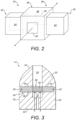
- Figure 2 shows a diagrammatic view of a vapour generating unit 34 according to examples of the disclosure.
- Figure 3 shows a cross-sectional view of a cartridge 14 comprising the vapour generating unit 34.
- the PTC heating element 38 comprises a pair of electrical contacts 40 for electrical coupling to the power source 32.
- the pair of electrical contacts 40 are provided on a body 46 of the PTC heating element 38.
- the PTC heating element 38 is arranged to hold and transfer a vapour generating liquid from the liquid store 22 by capillary action, i.e., by a wicking action. According, the PTC heating element 38 comprises a capillary material. The PTC heating element 38 thereby functions as both a heater and also a liquid transfer element (i.e., a wick). The PTC heating element 38 thereby provides a monolithic configuration in which wicking and heating functionalities are provided by a single element. Accordingly, a distinct and separate wick and heater (i.e., a heating wire) is not required.
- the PTC heating element 38 functions as a heater and is also arranged to hold and transfer a vapour generating liquid from the liquid store 22 by capillary action (i.e., the PTC heating element 38 also functions as a liquid transfer element). Combining these functions in a single element simplifies manufacture and assembly by reducing complexity and reduces cost and environmental impact. A potential failure mechanism is also removed.
- the porous PTC material comprises a porous PTC ceramic material, such as a porous PTC ceramic wick.
- the porous PTC ceramic material may be applied from a liquid ink or paste containing nanometre or micrometre sized particles.
- the porous PTC ceramic material may comprise a porous PTC composite ceramic material.
- the porous PTC ceramic material comprises a PTC oxide material, such as perovskite.
- the PTC oxide material comprises a BaTiO 3 -based material, which may be a BaTiO 3 -based material doped with Pb.
- the Pb-doped BaTiO 3 material is coated with a protective layer, i.e., a protective coating, such as a layer of epoxy resin.
- a protective coating such as a layer of epoxy resin.
- the Pb-doped BaTiO 3 material comprises a protective coating.
- the protective coating can be applied by a liquid coating process.
- the protective coating can be applied by an atomic layer deposition (ALD) or molecular layer deposition (MLD) process.
- the BaTiOs-based material may be doped with two or more donor materials.
- the BaTiO 3 -based material may be characterised as La-doped xBaTiO 3 -( 1-x )(BiyNa 1-y )TiO 3 (BT-BNT) ceramic.
- the BaTiO 3 -based material may be La-doped 95BaTiO 3 -5(Bi0.5Na0.5)TiO 3 (BT-BNT) ceramic, or a quasi-BaTiO 3 -based ternary perovskite material.
- the PTC oxide material may comprises a V 2 O 3 -based material.
- the porous PTC material comprises a porous PTC polymer composite.
- the cartridge 14 comprises a vaporisation chamber (not illustrated).
- the vaporisation chamber may be substantially cylindrical and centrally positioned in the cartridge 14.
- the vaporisation chamber is aligned with, and fluidly connected to, the vapour outlet channel 24.
- the vaporisation chamber may be disposed in the vapour outlet channel 24.
- the vaporisation chamber may be located in the vapour outlet channel 24.
- the vaporisation chamber provides a route which allows vapour generated by heating the vapour generating liquid to be transferred into the vapour outlet channel 24 where it cools and condenses to form an aerosol that can be inhaled by a user via the mouthpiece.
- vapour generated in the vaporisation chamber cools and condenses to form an aerosol as it flows along the vapour outlet channel 24, from the vaporisation chamber towards an end of the vapour outlet channel 24. Efficient vapour generation is thereby assured.
- a continuous process is achieved in which vapour generating liquid from the liquid store 22 is continuously absorbed by the PTC heating element 38 and heated to generate a vapour in the vaporisation chamber.
- the vaporisation of the vapour generating liquid is facilitated by the addition of air from the surrounding environment through the one or more air inlets (not illustrated).
- the flow of air and/or vapour may be aided by negative pressure created by a user drawing air through the mouthpiece.
- the PTC heating element 38 comprises a liquid supply element 42 providing an outer surface 44 which is exposed to the inner space of the liquid store 22.
- the liquid supply element 42 transfers vapour generating liquid from the liquid store 22 to the body 46 of the PTC heating element 38 by capillary action. Vapour generating liquid is thereby absorbed into the PTC heating element 38 via the outer surface 44 and is conveyed, for example by a wicking action, to the body 46 so that it can be heated and vaporised producing a vapour which cools and condenses to form an aerosol which may then be inhaled.
- An advantage of this arrangement is that it allows the delivery of liquid to the body 46 of the PTC heating element 38 to be carefully controlled whilst minimising heat transfer from the body 46 of the PTC heating element 38 to the vapour generating liquid in the liquid store 22.
- the PTC heating element 38 comprises two such liquid supply elements 42.
- vapour generating liquid is conveyed from the liquid store 22 to the PTC heating element 38 by capillary action.
- the vapour generating liquid is held and heated by the PTC heating element 38 resulting in the generation of a vapour.
- the vapour escapes from the PTC heating element 38 into the vaporisation chamber, and then flows from the vaporisation chamber along the vapour outlet channel 24 where it cools and condenses to form an aerosol that is inhaled by a user through the mouthpiece.
- the vaporisation of the vapour generating liquid is facilitated by the addition of air flowing from the surrounding environment through the one or more air inlets into the vaporisation chamber. Air then flows from the vaporisation chamber along the vapour outlet channel 24 to the mouthpiece. Vapour generated is entrained in the air as it flows into the vaporisation chamber and along the vapour outlet channel 24 to the mouthpiece.
- Examples of the disclosure also provide a cartridge 14 for a vapour generating device 12.
- the cartridge 14 comprises a vapour generating unit 34 as described above.
- Examples of the disclosure also provide a method.
- the method comprises holding and transferring a vapour generating liquid from the liquid store 22 by capillary action using the positive temperature coefficient (PTC) heating element 38 described above.
- the method further comprises heating, using the PTC heating element 38, the vapour generating liquid to form an aerosol.
- the method further comprises producing aerosol by the heating of the vapour generating liquid.
- PTC positive temperature coefficient
- the figures also illustrate a method of manufacturing a device 12, a cartridge 14, and a vapour generating unit 34 according to examples of the disclosure.
- the figures also illustrate a method of providing a system 10 according to examples of the disclosure.
Landscapes
- Engineering & Computer Science (AREA)
- Microelectronics & Electronic Packaging (AREA)
- Ceramic Engineering (AREA)
- Physics & Mathematics (AREA)
- Electromagnetism (AREA)
- Chemical & Material Sciences (AREA)
- Materials Engineering (AREA)
- Resistance Heating (AREA)
Abstract
A vapour generating unit (34). The vapour generating unit (34) comprises a vaporisation device (36). The vaporisation device (36) comprises a positive temperature coefficient (PTC) heating element (38) configured to electrically couple to a power source (32) to receive a current flow and heat a vapour generating liquid to form an aerosol. The PTC heating element (38) comprises a porous PTC material having an electrical resistivity that varies based on temperature. In use, when the PTC heating element (38) is heated to a transition temperature, electrical resistivity of the porous PTC material increases to reduce current flow from the power source (32) to a level that limits further temperature increases of the PTC heating element (38). The PTC heating element (38) is arranged to hold and transfer a vapour generating liquid from a liquid store (22) by capillary action.
Description
- The present disclosure relates generally to a vapour generating unit for a vapour generating device. The vapour generating device is configured to heat a vapour generating liquid to generate a vapour which cools and condenses to form an aerosol for inhalation by a user of the device.
- The term vapour generating device (or more commonly electronic cigarette or e-cigarette) refers to a handheld electronic device that is intended to simulate the feeling or experience of smoking tobacco in a traditional cigarette. Electronic cigarettes work by causing a vapour generating liquid (or so called "e-liquid") to be heated by a vapor generating unit to generate a vapour that cools and condenses to form an aerosol which is then inhaled by the user.
- Exceeding a required operating temperature of a vapour generating unit can lead to the formation of undesirable and potentially dangerous chemical by products.
- There is, therefore, a need to provide vapor generating units which mitigate this drawback.
- According to a first aspect of the present disclosure, there is provided a vapour generating unit, the vapour generating unit comprising a vaporisation device, the vaporisation device comprising a positive temperature coefficient (PTC) heating element configured to electrically couple to a power source to receive a current flow and heat a vapour generating liquid to form an aerosol, wherein the PTC heating element comprises a porous PTC material having an electrical resistivity that varies based on temperature, wherein in use when the PTC heating element is heated to a transition temperature, electrical resistivity of the porous PTC material increases to reduce current flow from the power source to a level that limits further temperature increases of the PTC heating element, wherein the PTC heating element is arranged to hold and transfer a vapour generating liquid from a liquid store by capillary action.
- The electrical resistivity of the porous PTC material significantly changes at the transition temperature. Accordingly, the PTC heating element is temperature self-limiting; a sharp increase in resistance reduces current flow from the power source to a level that limits further temperature increases of the PTC heating element.
- The PTC heating element therefore enables a device with intrinsic temperature control at or near a desired operating temperature of the device, which operating temperature substantially corresponds to the transition temperature. By utilizing a PTC heating element with intrinsic temperature control, overheating (e.g., burning) of the vapour generating liquid can be prevented, thereby avoiding formation of unwanted, and potentially dangerous, chemical by products. Accordingly, in use a required operating temperature can be maintained without the need for temperature sensors, electronic circuitry, or controllers.
- In this arrangement the PTC heating element functions as a heater and is also arranged to hold and transfer a vapour generating liquid from the liquid store by capillary action. Combining these functions in a single element simplifies manufacture and assembly by reducing complexity and reduces cost and environmental impact.
- The transition temperature may be from 160°C to 320°C. Preferably, the transition temperature may be from 180°C to 300°C. At these transition temperature ranges, evaporation is achieved without the generation of potentially harmful chemical species.
- The electrical resistivity of the porous PTC material may increase by at least a factor of 100 beginning at the transition temperature and ending at a temperature of up to 10°C above the transition temperature.
- The porous PTC material may comprise a porous PTC ceramic material. The porous PTC ceramic material may comprise a PTC oxide material. The PTC oxide material may comprise perovskite. Alternatively, the PTC oxide material may comprise a BaTiOs-based material. The BaTiO3-based material may be doped with Pb. The Pb-doped BaTiO3 material may comprise a protective coating. The BaTiO3-based material may be La-doped 95BaTiO3-5(Bi0.5Na0.5)TiO3 (BT-BNT) ceramic. Alternatively, the BaTiO3-based material may be a quasi-BaTiO3-based ternary perovskite material. In other examples, the PTC oxide material may comprise a V2O3-based material.
- Alternatively, the porous PTC material may comprise a PTC polymer composite.
- According to a second aspect of the present disclosure, there is provided a cartridge for a vapour generating device, wherein the cartridge comprises a vapour generating unit according to any of the above paragraphs.
- According to a third aspect of the present disclosure, there is provided a method comprising:
- holding and transferring a vapour generating liquid from a liquid store by capillary action using a positive temperature coefficient (PTC) heating element of a vaporisation device comprised in a vapour generating unit;
- heating, using the PTC heating element, the vapour generating liquid to form an aerosol, the PTC heating element being configured to electrically couple to a power source to receive a current flow to heat the vapour generating liquid, wherein the PTC heating element comprises a porous PTC material having an electrical resistivity that varies based on temperature, wherein when the PTC heating element is heated to a transition temperature, electrical resistivity of the porous PTC material increases to reduce current flow from the power source to a level that limits further temperature increases of the PTC heating element; and
- producing aerosol by the heating of the vapour generating liquid.
-
-
Figure 1 is a diagrammatic view of a vapour generating system comprising a vapour generating device and a cartridge; -
Figure 2 is a diagrammatic view of a vapour generating unit for a vapour generating system exemplified inFigure 1 ; and -
Figure 3 is a diagrammatic cross-sectional view of a cartridge comprising the vapour generating unit ofFigure 2 . - Embodiments of the present disclosure will now be described by way of example only and with reference to the accompanying drawings.
- Referring initially to
Figure 1 there is shown avapour generating system 10. In the illustrated example, thevapour generating system 10 comprises avapour generating device 12 and acartridge 14 configured to be used with thevapour generating device 12. - The
vapour generating device 12 may be elongate and have a substantially cylindrical shape which resembles a cigarette or cigar. Other shapes are, however, entirely within the scope of the present disclosure. - The term vapour generating device 12 (or more commonly electronic cigarette or e-cigarette) refers to a handheld electronic device that is intended to simulate the feeling or experience of smoking tobacco in a traditional cigarette. Electronic cigarettes work by causing a vapour generating liquid to be heated to generate a vapour that cools and condenses to form an aerosol which is then inhaled by the user. Accordingly, using e-cigarettes is also sometimes referred to as "vaping". Vapour generating liquid is sometimes referred to as e-liquid.
- In general terms, a vapour is a substance in the gas phase at a temperature lower than its critical temperature, which means that the vapour can be condensed to a liquid by increasing its pressure without reducing the temperature, whereas an aerosol is a suspension of fine solid particles or liquid droplets, in air or another gas. It should, however, be noted that the terms 'aerosol' and 'vapour' may be used interchangeably in this specification, particularly with regard to the form of the inhalable medium that is generated for inhalation by a user.
- The vapour generating liquid, i.e., liquid vaporizable material, may comprise polyhydric alcohols and mixtures thereof such as glycerine or propylene glycol. The vapour generating liquid may contain nicotine. The vapour generating liquid may also comprise flavourings such as tobacco, menthol or fruit flavour. In some examples, the vapour generating liquid has a low vegetable glycerine content and/or added water to reduce its boiling point.
- The
cartridge 14 comprises ahousing 16 having aproximal end 18 and adistal end 20. Theproximal end 18 may constitutes a mouthpiece, i.e., a mouthpiece end, configured for being introduced directly into a user's mouth and may, therefore, also be designated as the mouth end. The mouthpiece provides the ability for a user to easily inhale aerosol generated by thevapour generating device 12. - The
cartridge 14 comprises aliquid store 22 for containing, i.e., for holding or storing, a vapour generating liquid. Accordingly, theliquid store 22 is configured for containing therein a vapour generating liquid. - The
liquid store 22 may extend generally between the proximal (mouth)end 18 and thedistal end 20. Thecartridge 14 comprises avapour outlet channel 24. Thevapour outlet channel 24 is fluidly connected to the mouthpiece at theproximal end 18. In some examples, theliquid store 22 surrounds, and coextends with, thevapour outlet channel 24. - The
vapour generating device 12 includes acontroller 26. Thevapour generating device 12 includes auser interface 28 for controlling the operation of thevapour generating device 12 via thecontroller 26 and/or for displaying information. In some examples, theuser interface 28 may be comprised in a separate device such as a mobile device. - The
controller 26 is configured to detect the initiation of use of thevapour generating device 12 in response to a user input, such as a button press to activate thevapour generating device 12, or in response to a detected airflow through thevapour generating device 12. As will be understood by one of ordinary skill in the art, an airflow through thevapour generating device 12 is indicative of a user inhalation or 'puff'. Thevapour generating device 12 may, for example, include a puff detector (not shown), such as an airflow sensor, to detect an airflow through thevapour generating device 12. - The
controller 26 includeselectronic circuitry 30. Thevapour generating device 12 includes apower source 32, such as a battery. Thepower source 32 and theelectronic circuitry 30 may be configured to operate at a high frequency. - The
cartridge 14 may be releasably connectable to thevapour generating device 12 by a releasable connection. The releasable connection can, for example, be a snap-fit connection or alternatively, a magnetic connection, a threaded connection, or a bayonet connection. Accordingly, after the vapour generating liquid in theliquid store 22 of thecartridge 14 has been depleted, thecartridge 14 can be disconnected from thevapour generating device 12 and areplacement cartridge 14 can then be connected in its place, to allow further use of thevapour generating device 12. Thecartridge 14 may be disposable. Alternatively, in some examples thecartridge 14 may be re-filled with vapour generating liquid so that thecartridge 14 can be re-used. - The
cartridge 12 comprises avapour generating unit 34. Thevapour generating unit 34 comprises avaporisation device 36. - The
vaporisation device 36 comprises a positive temperature coefficient (PTC)heating element 38, i.e., aheater 38, configured to electrically couple to thepower source 32 to receive a current flow and heat the vapour generating liquid to form an aerosol. - The
PTC heating element 38 comprises a porous PTC material having an electrical resistivity that varies based on temperature. - In use, when the
PTC heating element 38 is heated to a transition temperature, electrical resistivity of the porous PTC material increases to reduce current flow from thepower source 32 to a level that limits further temperature increases of thePTC heating element 38. - The electrical resistivity of the porous PTC material significantly changes at the transition temperature. Accordingly, the
PTC heating element 38 is temperature self-limiting; a sharp increase in resistance reduces current flow from thepower source 32 to a level that limits further temperature increases of thePTC heating element 38. - The
PTC heating element 38 therefore enables adevice 12 with intrinsic temperature control at or near a desired operating temperature of thedevice 12, which operating temperature substantially corresponds to the transition temperature. By utilizing aPTC heating element 38 with intrinsic temperature control, overheating (e.g., burning) of the vapour generating liquid can be prevented, thereby avoiding formation of unwanted, and potentially dangerous, chemical by products. Accordingly, in use a required operating temperature can be maintained without the need for temperature sensors, electronic circuitry, or controllers. Temperature overshoot is therefore avoided which can otherwise lead to the formation of undesirable and potentially dangerous chemical by products. - The transition temperature may be understood as a critical temperature or switch temperature. The electrical resistivity of the porous PTC material can be increased by as much as several orders of magnitude within a temperature span of a few degrees. Accordingly, the transition temperature is the temperature at which electrical resistance starts to increase sharply.
- In some examples, the electrical resistivity of the porous PTC material increases by at least a factor of 100 at the transition temperature. The electrical resistivity of the porous PTC material may increase by at least a factor of 100 beginning at the transition temperature and ending at a temperature of up to 10°C above the transition temperature.
- In some examples, the transition temperature is from 160°C to 320°C. Preferably, the transition temperature is from 180°C to 300°C. At these transition temperature ranges, evaporation is achieved without the generation of potentially harmful chemical species.
-
Figure 2 shows a diagrammatic view of avapour generating unit 34 according to examples of the disclosure.Figure 3 shows a cross-sectional view of acartridge 14 comprising thevapour generating unit 34. - Referring to
Figures 2 and 3 , thePTC heating element 38 comprises a pair ofelectrical contacts 40 for electrical coupling to thepower source 32. The pair ofelectrical contacts 40 are provided on abody 46 of thePTC heating element 38. - The
PTC heating element 38 is arranged to hold and transfer a vapour generating liquid from theliquid store 22 by capillary action, i.e., by a wicking action. According, thePTC heating element 38 comprises a capillary material. ThePTC heating element 38 thereby functions as both a heater and also a liquid transfer element (i.e., a wick). ThePTC heating element 38 thereby provides a monolithic configuration in which wicking and heating functionalities are provided by a single element. Accordingly, a distinct and separate wick and heater (i.e., a heating wire) is not required. - As described above, in this arrangement the
PTC heating element 38 functions as a heater and is also arranged to hold and transfer a vapour generating liquid from theliquid store 22 by capillary action (i.e., thePTC heating element 38 also functions as a liquid transfer element). Combining these functions in a single element simplifies manufacture and assembly by reducing complexity and reduces cost and environmental impact. A potential failure mechanism is also removed. - Furthermore, in examples of the disclosure there is efficient heat transfer between the
PTC heating element 38 and the vapour generating liquid (i.e., e-liquid) held therein. This is crucial for the performance of the device 12 (i.e., e-cigarettes). This is achieved because the contact area between thePTC heating element 38 and e-liquid held therein is maximised leading to improved device efficiency and faster heat-up time. In conventional arrangements, the contact area between heater and e-liquid is limited, and the temperature will therefore rapidly drop away from the point of contact leading to reduced device efficiency and slower heat up time. - In some examples, the porous PTC material comprises a porous PTC ceramic material, such as a porous PTC ceramic wick. The porous PTC ceramic material may be applied from a liquid ink or paste containing nanometre or micrometre sized particles.
- The porous PTC ceramic material may comprise a porous PTC composite ceramic material. In some examples, the porous PTC ceramic material comprises a PTC oxide material, such as perovskite.
- In other examples, the PTC oxide material comprises a BaTiO3-based material, which may be a BaTiO3-based material doped with Pb. In some examples, the Pb-doped BaTiO3 material is coated with a protective layer, i.e., a protective coating, such as a layer of epoxy resin. Accordingly, in such examples the Pb-doped BaTiO3 material comprises a protective coating. The protective coating can be applied by a liquid coating process. Alternatively, the protective coating can be applied by an atomic layer deposition (ALD) or molecular layer deposition (MLD) process.
- The BaTiOs-based material may be doped with two or more donor materials. The BaTiO3-based material may be characterised as La-doped xBaTiO3-(1-x)(BiyNa1-y)TiO3 (BT-BNT) ceramic. The BaTiO3-based material may be La-doped 95BaTiO3-5(Bi0.5Na0.5)TiO3 (BT-BNT) ceramic, or a quasi-BaTiO3-based ternary perovskite material.
- In some examples, the PTC oxide material may comprises a V2O3-based material.
- In other examples, the porous PTC material comprises a porous PTC polymer composite.
- The
cartridge 14 comprises a vaporisation chamber (not illustrated). The vaporisation chamber may be substantially cylindrical and centrally positioned in thecartridge 14. The vaporisation chamber is aligned with, and fluidly connected to, thevapour outlet channel 24. The vaporisation chamber may be disposed in thevapour outlet channel 24. The vaporisation chamber may be located in thevapour outlet channel 24. The vaporisation chamber provides a route which allows vapour generated by heating the vapour generating liquid to be transferred into thevapour outlet channel 24 where it cools and condenses to form an aerosol that can be inhaled by a user via the mouthpiece. The vapour generated in the vaporisation chamber cools and condenses to form an aerosol as it flows along thevapour outlet channel 24, from the vaporisation chamber towards an end of thevapour outlet channel 24. Efficient vapour generation is thereby assured. In particular, a continuous process is achieved in which vapour generating liquid from theliquid store 22 is continuously absorbed by thePTC heating element 38 and heated to generate a vapour in the vaporisation chamber. - The vaporisation of the vapour generating liquid is facilitated by the addition of air from the surrounding environment through the one or more air inlets (not illustrated). The flow of air and/or vapour may be aided by negative pressure created by a user drawing air through the mouthpiece.
- In the illustrated example, the
PTC heating element 38 comprises aliquid supply element 42 providing anouter surface 44 which is exposed to the inner space of theliquid store 22. Theliquid supply element 42 transfers vapour generating liquid from theliquid store 22 to thebody 46 of thePTC heating element 38 by capillary action. Vapour generating liquid is thereby absorbed into thePTC heating element 38 via theouter surface 44 and is conveyed, for example by a wicking action, to thebody 46 so that it can be heated and vaporised producing a vapour which cools and condenses to form an aerosol which may then be inhaled. - An advantage of this arrangement is that it allows the delivery of liquid to the
body 46 of thePTC heating element 38 to be carefully controlled whilst minimising heat transfer from thebody 46 of thePTC heating element 38 to the vapour generating liquid in theliquid store 22. - In the example illustrated in
Figures 2 and 3 , thePTC heating element 38 comprises two suchliquid supply elements 42. - In operation of the
vapour generating system 10, vapour generating liquid is conveyed from theliquid store 22 to thePTC heating element 38 by capillary action. The vapour generating liquid is held and heated by thePTC heating element 38 resulting in the generation of a vapour. The vapour escapes from thePTC heating element 38 into the vaporisation chamber, and then flows from the vaporisation chamber along thevapour outlet channel 24 where it cools and condenses to form an aerosol that is inhaled by a user through the mouthpiece. - The vaporisation of the vapour generating liquid is facilitated by the addition of air flowing from the surrounding environment through the one or more air inlets into the vaporisation chamber. Air then flows from the vaporisation chamber along the
vapour outlet channel 24 to the mouthpiece. Vapour generated is entrained in the air as it flows into the vaporisation chamber and along thevapour outlet channel 24 to the mouthpiece. - The flow of air and/or vapour through the
cartridge 14, i.e., through the vaporisation chamber, along thevapour outlet channel 24, and out of the mouthpiece, is aided by negative pressure created by a user drawing air through the mouthpiece. - Examples of the disclosure also provide a
cartridge 14 for avapour generating device 12. Thecartridge 14 comprises avapour generating unit 34 as described above. - Examples of the disclosure also provide a method. The method comprises holding and transferring a vapour generating liquid from the
liquid store 22 by capillary action using the positive temperature coefficient (PTC)heating element 38 described above. The method further comprises heating, using thePTC heating element 38, the vapour generating liquid to form an aerosol. The method further comprises producing aerosol by the heating of the vapour generating liquid. - The figures also illustrate a method of manufacturing a
device 12, acartridge 14, and avapour generating unit 34 according to examples of the disclosure. The figures also illustrate a method of providing asystem 10 according to examples of the disclosure. - Although exemplary embodiments have been described in the preceding paragraphs, it should be understood that various modifications may be made to those embodiments without departing from the scope of the appended claims. Thus, the breadth and scope of the claims should not be limited to the above-described exemplary embodiments.
- Any combination of the above-described features in all possible variations thereof is encompassed by the present disclosure unless otherwise indicated herein or otherwise clearly contradicted by context.
- Unless the context clearly requires otherwise, throughout the description and the claims, the words "comprise", "comprising", and the like, are to be construed in an inclusive as opposed to an exclusive or exhaustive sense; that is to say, in the sense of "including, but not limited to".
Claims (15)
- A vapour generating unit (34), the vapour generating unit (34) comprising a vaporisation device (36), the vaporisation device (36) comprising a positive temperature coefficient (PTC) heating element (38) configured to electrically couple to a power source (32) to receive a current flow and heat a vapour generating liquid to form an aerosol, wherein the PTC heating element (38) comprises a porous PTC material having an electrical resistivity that varies based on temperature, wherein in use when the PTC heating element (38) is heated to a transition temperature, electrical resistivity of the porous PTC material increases to reduce current flow from the power source (32) to a level that limits further temperature increases of the PTC heating element (38), wherein the PTC heating element (38) is arranged to hold and transfer a vapour generating liquid from a liquid store (22) by capillary action.
- A vapour generating unit according to claim 1, wherein the transition temperature is from 160°C to 320°C.
- A vapour generating unit according to claim 1 or 2, wherein the transition temperature is from 180°C to 300°C.
- A vapour generating unit according to any of the preceding claims, wherein the electrical resistivity of the porous PTC material increases by at least a factor of 100 beginning at the transition temperature and ending at a temperature of up to 10°C above the transition temperature.
- A vapour generating unit according to any of the preceding claims, wherein the porous PTC material comprises a porous PTC ceramic material.
- A vapour generating unit according to claim 5, wherein the porous PTC ceramic material comprises a PTC oxide material.
- A vapour generating unit according to claim 6, wherein the PTC oxide material comprises perovskite.
- A vapour generating unit according to claim 6, wherein the PTC oxide material comprises a BaTiO3-based material.
- A vapour generating unit according to claim 8, wherein the BaTiO3-based material is doped with Pb.
- A vapour generating unit according to claim 8, wherein, the BaTiO3-based material is La-doped 95BaTiO3-5(Bi0.5Na0.5)TiO3 (BT-BNT) ceramic.
- A vapour generating unit according to claim 8, wherein the BaTiO3-based material is a quasi-BaTiO3-based ternary perovskite material.
- A vapour generating unit according to claim 6, wherein the PTC oxide material comprises a V2O3-based material.
- A vapour generating unit according to any of claims 1 to 4, wherein the porous PTC material comprises a PTC polymer composite.
- A cartridge (14) for a vapour generating device (12), wherein the cartridge (14) comprises a vapour generating unit (34) according to any of the preceding claims.
- A method comprising:holding and transferring a vapour generating liquid from a liquid store (22) by capillary action using a positive temperature coefficient (PTC) heating element (38) of a vaporisation device (36) comprised in a vapour generating unit (34);heating, using the PTC heating element (38), the vapour generating liquid to form an aerosol, the PTC heating element (38) being configured to electrically couple to a power source (32) to receive a current flow to heat the vapour generating liquid, wherein the PTC heating element (38) comprises a porous PTC material having an electrical resistivity that varies based on temperature, wherein when the PTC heating element (38) is heated to a transition temperature, electrical resistivity of the porous PTC material increases to reduce current flow from the power source (32) to a level that limits further temperature increases of the PTC heating element (38); andproducing aerosol by the heating of the vapour generating liquid.
Priority Applications (1)
| Application Number | Priority Date | Filing Date | Title |
|---|---|---|---|
| EP23183526.5A EP4489519A1 (en) | 2023-07-05 | 2023-07-05 | Vapour generating unit |
Applications Claiming Priority (1)
| Application Number | Priority Date | Filing Date | Title |
|---|---|---|---|
| EP23183526.5A EP4489519A1 (en) | 2023-07-05 | 2023-07-05 | Vapour generating unit |
Publications (1)
| Publication Number | Publication Date |
|---|---|
| EP4489519A1 true EP4489519A1 (en) | 2025-01-08 |
Family
ID=87136384
Family Applications (1)
| Application Number | Title | Priority Date | Filing Date |
|---|---|---|---|
| EP23183526.5A Withdrawn EP4489519A1 (en) | 2023-07-05 | 2023-07-05 | Vapour generating unit |
Country Status (1)
| Country | Link |
|---|---|
| EP (1) | EP4489519A1 (en) |
Citations (5)
| Publication number | Priority date | Publication date | Assignee | Title |
|---|---|---|---|---|
| US20170196273A1 (en) * | 2014-12-12 | 2017-07-13 | Joyetech (Changzhou) Electronics Co., Ltd. | Atomizing device and electronic cigarette having same |
| US20210084982A1 (en) * | 2017-12-06 | 2021-03-25 | Nicoventures Trading Limited | Component for an aerosol-generating apparatus |
| WO2022106612A1 (en) * | 2020-11-19 | 2022-05-27 | Schott Ag | Electrically conductive porous sintering body comprising at least two electrically conductive materials, and method for producing same |
| WO2022106613A1 (en) * | 2020-11-19 | 2022-05-27 | Schott Ag | Electrically conductive, porous sintered body |
| US20230057645A1 (en) * | 2020-04-26 | 2023-02-23 | Shenzhen Smoore Technology Limited | Heating assembly, atomizer and electronic atomization device |
-
2023
- 2023-07-05 EP EP23183526.5A patent/EP4489519A1/en not_active Withdrawn
Patent Citations (5)
| Publication number | Priority date | Publication date | Assignee | Title |
|---|---|---|---|---|
| US20170196273A1 (en) * | 2014-12-12 | 2017-07-13 | Joyetech (Changzhou) Electronics Co., Ltd. | Atomizing device and electronic cigarette having same |
| US20210084982A1 (en) * | 2017-12-06 | 2021-03-25 | Nicoventures Trading Limited | Component for an aerosol-generating apparatus |
| US20230057645A1 (en) * | 2020-04-26 | 2023-02-23 | Shenzhen Smoore Technology Limited | Heating assembly, atomizer and electronic atomization device |
| WO2022106612A1 (en) * | 2020-11-19 | 2022-05-27 | Schott Ag | Electrically conductive porous sintering body comprising at least two electrically conductive materials, and method for producing same |
| WO2022106613A1 (en) * | 2020-11-19 | 2022-05-27 | Schott Ag | Electrically conductive, porous sintered body |
Similar Documents
| Publication | Publication Date | Title |
|---|---|---|
| JP7596349B2 (en) | Aerosol generating system with heated gel container | |
| JP7382347B2 (en) | Detection of harmful heater conditions in electrically heated aerosol generation systems | |
| CN111713747B (en) | Aerosol generating systems and cartridges for use in aerosol generating systems | |
| EP3890529B1 (en) | Aerosol generating system and cartridge with leakage protection | |
| CN108289510B (en) | Electrically operated aerosol-generating system with liquid pump | |
| JP2024069625A (en) | Aerosol generating system including a gel-containing cartridge and a device for heating the cartridge - Patents.com | |
| KR102148142B1 (en) | An aerosol generating device with a capillary interface | |
| CN106510005B (en) | Electrically heated smoking system with liquid storage portion | |
| US12089637B2 (en) | Aerosol generating system and cartridge with leakage protection | |
| KR20160140608A (en) | Electrically heated aerosol-generating system | |
| KR102829865B1 (en) | Aerosol generating device having angled evaporator | |
| KR102840862B1 (en) | Leak-protected aerosol generating system and cartridge | |
| KR102932737B1 (en) | Aerosol generating device with humidity sensor and humidifier | |
| WO2023104703A1 (en) | An aerosol generating system | |
| CN116744811A (en) | Handheld aerosol generating device with opening element | |
| HK1228211B (en) | An aerosol-generating device with a capillary interface | |
| HK1228211A1 (en) | An aerosol-generating device with a capillary interface |
Legal Events
| Date | Code | Title | Description |
|---|---|---|---|
| PUAI | Public reference made under article 153(3) epc to a published international application that has entered the european phase |
Free format text: ORIGINAL CODE: 0009012 |
|
| STAA | Information on the status of an ep patent application or granted ep patent |
Free format text: STATUS: THE APPLICATION HAS BEEN PUBLISHED |
|
| AK | Designated contracting states |
Kind code of ref document: A1 Designated state(s): AL AT BE BG CH CY CZ DE DK EE ES FI FR GB GR HR HU IE IS IT LI LT LU LV MC ME MK MT NL NO PL PT RO RS SE SI SK SM TR |
|
| STAA | Information on the status of an ep patent application or granted ep patent |
Free format text: STATUS: THE APPLICATION IS DEEMED TO BE WITHDRAWN |
|
| 18D | Application deemed to be withdrawn |
Effective date: 20250709 |