EP4489462A1 - Control device for improving communication efficiency of cell-free massive mimo system configured from multiple antennas, control method therefor, processing device, processing method therefor, and program - Google Patents
Control device for improving communication efficiency of cell-free massive mimo system configured from multiple antennas, control method therefor, processing device, processing method therefor, and program Download PDFInfo
- Publication number
- EP4489462A1 EP4489462A1 EP23763357.3A EP23763357A EP4489462A1 EP 4489462 A1 EP4489462 A1 EP 4489462A1 EP 23763357 A EP23763357 A EP 23763357A EP 4489462 A1 EP4489462 A1 EP 4489462A1
- Authority
- EP
- European Patent Office
- Prior art keywords
- terminal device
- antennas
- processing
- antenna
- ric
- Prior art date
- Legal status (The legal status is an assumption and is not a legal conclusion. Google has not performed a legal analysis and makes no representation as to the accuracy of the status listed.)
- Pending
Links
Images


Classifications
-
- H—ELECTRICITY
- H04—ELECTRIC COMMUNICATION TECHNIQUE
- H04B—TRANSMISSION
- H04B7/00—Radio transmission systems, i.e. using radiation field
- H04B7/02—Diversity systems; Multi-antenna system, i.e. transmission or reception using multiple antennas
- H04B7/04—Diversity systems; Multi-antenna system, i.e. transmission or reception using multiple antennas using two or more spaced independent antennas
- H04B7/06—Diversity systems; Multi-antenna system, i.e. transmission or reception using multiple antennas using two or more spaced independent antennas at the transmitting station
- H04B7/0686—Hybrid systems, i.e. switching and simultaneous transmission
- H04B7/0691—Hybrid systems, i.e. switching and simultaneous transmission using subgroups of transmit antennas
-
- H—ELECTRICITY
- H04—ELECTRIC COMMUNICATION TECHNIQUE
- H04L—TRANSMISSION OF DIGITAL INFORMATION, e.g. TELEGRAPHIC COMMUNICATION
- H04L5/00—Arrangements affording multiple use of the transmission path
- H04L5/003—Arrangements for allocating sub-channels of the transmission path
- H04L5/0048—Allocation of pilot signals, i.e. of signals known to the receiver
-
- H—ELECTRICITY
- H04—ELECTRIC COMMUNICATION TECHNIQUE
- H04W—WIRELESS COMMUNICATION NETWORKS
- H04W16/00—Network planning, e.g. coverage or traffic planning tools; Network deployment, e.g. resource partitioning or cells structures
- H04W16/24—Cell structures
- H04W16/28—Cell structures using beam steering
-
- H—ELECTRICITY
- H04—ELECTRIC COMMUNICATION TECHNIQUE
- H04W—WIRELESS COMMUNICATION NETWORKS
- H04W72/00—Local resource management
- H04W72/20—Control channels or signalling for resource management
-
- H—ELECTRICITY
- H04—ELECTRIC COMMUNICATION TECHNIQUE
- H04W—WIRELESS COMMUNICATION NETWORKS
- H04W72/00—Local resource management
- H04W72/50—Allocation or scheduling criteria for wireless resources
- H04W72/54—Allocation or scheduling criteria for wireless resources based on quality criteria
-
- H—ELECTRICITY
- H04—ELECTRIC COMMUNICATION TECHNIQUE
- H04W—WIRELESS COMMUNICATION NETWORKS
- H04W88/00—Devices specially adapted for wireless communication networks, e.g. terminals, base stations or access point devices
- H04W88/08—Access point devices
-
- H—ELECTRICITY
- H04—ELECTRIC COMMUNICATION TECHNIQUE
- H04W—WIRELESS COMMUNICATION NETWORKS
- H04W88/00—Devices specially adapted for wireless communication networks, e.g. terminals, base stations or access point devices
- H04W88/08—Access point devices
- H04W88/085—Access point devices with remote components
-
- H—ELECTRICITY
- H04—ELECTRIC COMMUNICATION TECHNIQUE
- H04W—WIRELESS COMMUNICATION NETWORKS
- H04W88/00—Devices specially adapted for wireless communication networks, e.g. terminals, base stations or access point devices
- H04W88/12—Access point controller devices
-
- H—ELECTRICITY
- H04—ELECTRIC COMMUNICATION TECHNIQUE
- H04B—TRANSMISSION
- H04B7/00—Radio transmission systems, i.e. using radiation field
- H04B7/02—Diversity systems; Multi-antenna system, i.e. transmission or reception using multiple antennas
- H04B7/022—Site diversity; Macro-diversity
- H04B7/024—Co-operative use of antennas of several sites, e.g. in co-ordinated multipoint or co-operative multiple-input multiple-output [MIMO] systems
-
- Y—GENERAL TAGGING OF NEW TECHNOLOGICAL DEVELOPMENTS; GENERAL TAGGING OF CROSS-SECTIONAL TECHNOLOGIES SPANNING OVER SEVERAL SECTIONS OF THE IPC; TECHNICAL SUBJECTS COVERED BY FORMER USPC CROSS-REFERENCE ART COLLECTIONS [XRACs] AND DIGESTS
- Y02—TECHNOLOGIES OR APPLICATIONS FOR MITIGATION OR ADAPTATION AGAINST CLIMATE CHANGE
- Y02D—CLIMATE CHANGE MITIGATION TECHNOLOGIES IN INFORMATION AND COMMUNICATION TECHNOLOGIES [ICT], I.E. INFORMATION AND COMMUNICATION TECHNOLOGIES AIMING AT THE REDUCTION OF THEIR OWN ENERGY USE
- Y02D30/00—Reducing energy consumption in communication networks
- Y02D30/70—Reducing energy consumption in communication networks in wireless communication networks
Definitions
- the present invention relates to a technology for improving a communication efficiency in a cell-free massive MIMO system composed of many antennas.
- each terminal device can obtain uniform communication quality irrespective of its location.
- a processing device connected to antennas forms a virtual cell for each terminal device by controlling those antennas.
- the number of antennas and terminal devices is enormous, and therefore, it is not easy to control the system with use of a single processing device. Accordingly, a configuration is contemplated in which a plurality of processing devices each configured to control a portion of the antennas are prepared, and each terminal device performs communication by establishing connection with any of the processing devices.
- a terminal device is present at a position around an end portion of an area in which communication can be performed using antennas controlled by a processing device to which the terminal device has been connected
- another processing device controlling antennas forming an area that allows communication at that position may be involved in communication performed by the terminal device.
- the other processing device may receive a signal transmitted from the terminal device and transfer the signal to the processing device to which the terminal device has been connected, and the processing device may perform signal processing such as demodulation by using signals received by antennas connected to the processing device itself and the transferred signal (NPL 1).
- NPL1 C. D' Andrea and E. G. Larsson, "User association in scalable cell-free massive MIMO systems", 2020 54th Asilomar Conference on Signals, Systems, and Computers, 2020
- the present invention provides a technology for improving a communication efficiency in a cell-free massive MIMO system including a plurality of processing devices connected to one or more antennas.
- a control device is a control device that functions as a RAN Intelligent Controller (RIC) in an Open-Radio Access Network (O-RAN), the control device comprising: identification means for identifying, with respect to each of a plurality of terminal devices, a plurality of antennas that are expected to receive, with at least a predetermined power, a signal transmitted from the terminal device, based on locations of the plurality of terminal devices; and notification means for notifying an O-RAN Distributed Unit (O-DU) that is connected to one or more first antennas included in the plurality of antennas for a first terminal device and executes demodulation and decoding processing for the first terminal device, and is connected to one or more second antennas included in the plurality of antennas for a second terminal device and does not execute demodulation and decoding processing for the second terminal device, of information indicating the one or more first antennas and information indicating a third antenna among the one or more second antennas, the third antenna being a target of transmission path estimation performed based on pilot symbols received from the
- a processing device is a processing device that functions as an O-RAN Distributed Unit (O-DU) connected to a plurality of antennas to perform radio communication with a terminal device in an Open-Radio Access Network (O-RAN), the processing device comprising: receiving means for receiving information indicating one or more first antennas that receive a signal transmitted from a first terminal device that is a target of signal demodulation and decoding processing, among the plurality of antennas, and information indicating a third antenna among one or more second antennas that receive a signal transmitted from a second terminal device that is not a target of signal demodulation and decoding processing, among the plurality of antennas, the third antenna being a target of transmission path estimation performed based on pilot symbols received from the second terminal device; estimation means for estimating a transmission path between the third antenna and the second terminal device; and execution means for executing communication processing for the first terminal device by using a result of the transmission path estimation.
- O-RAN Distributed Unit O-RAN Distributed Unit
- the present invention it is possible to improve a communication efficiency in a cell-free massive MIMO system including a plurality of processing devices connected to one or more antennas.
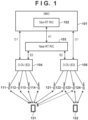
- FIG. 1 shows a configuration example of a radio communication system according to the present embodiment.
- the radio communication system is a cell-free massive MIMO system in which many antennas (e.g., antennas 111 to 114 and antennas 121 to 124) are geographically distributed and a radio communication service is provided to terminal devices (e.g., a terminal device 131 and a terminal device 132) by forming a virtual cell for each terminal device with use of a portion of the antennas.
- many antennas are divided into a plurality of groups, the groups are respectively connected to different processing devices, and the processing devices control antenna weights, perform encoding and modulation of signals to be transmitted by the antennas, and demodulation and decoding of signals received by the antennas, for example.
- Such a processing device may be called a central processing unit (CPU), for example.
- a virtual CPU may be set for each terminal device, and the virtual CPU may execute communication processing for the corresponding terminal device.
- Such a virtual CPU may also be called a vCPU.
- the antennas may be antennas that have a function of capturing electromagnetic waves or radiating electromagnetic waves, or communication devices that have a function of executing certain processing such as frequency conversion or amplification, for example. Such antennas may be called "access points (AP)", for example.
- the radio communication system is configured using Open-Radio Access Network (O-RAN), standardization of which is promoted to make radio access networks (RANs) open and intelligent.
- O-RAN Open-Radio Access Network
- a RAN is made intelligent by controlling a plurality of O-DUs (E2 nodes) connected to terminal devices with use of control devices that are called RAN Intelligent Controllers (RICs).
- O-DU is abbreviation for O-RAN Distributed Unit, and an O-DU as used herein corresponds to a processing device directly connected to antennas.
- the antennas 111 to 114 are connected to an O-DU 104, and the antennas 121 to 124 are connected to an O-DU 105.
- the RICs include a Near-RT RIC 103 that performs short period control in substantially real time (RT) and a Non-RT RIC 102 that performs long period control not in real time.
- RT substantially real time
- Non-RT RIC 102 is configured as a portion of Service Management and Orchestration (SMO 101).
- the Non-RT RIC 102 performs long term control such as RAN analysis and policy management.
- the Near-RT RIC 103 controls O-DUs in accordance with policies determined by the Non-RT RIC 102.
- an interface called "O1 interface” is set between the Non-RT RIC 102 (SMO 101) and the O-DUs
- an A1 interface is set between the Non-RT RIC 102 and the Near-RT RIC 103
- an E2 interface is set between the Near-RT RIC 013 and the O-DUs.
- an interface (not shown) that enables direct communication between an O-DU and another O-DU may be prepared between the O-DUs.
- the terminal device 131 is located near the boundary between an area in which communication can be performed via the antennas 111 to 114 and an area in which communication can be performed via the antennas 121 and 122, for example.
- the antennas 111 to 114 and the antennas 121 and 122 may be used in communication performed by the terminal device 131.
- a signal transmitted from the terminal device 131 is received by the antennas 111 to 114 and the antennas 121 and 122.
- the signal received by the antennas 121 and 122 may be transferred from the O-DU 105 to the O-DU 104.
- the O-DU 104 may demodulate and decode the signal transmitted from the terminal device 131 by using the signal received via the antennas 111 to 114 and the signal received via the antennas 121 and 122.
- data to be transmitted to the terminal device 131 is provided to the O-DU 104 and the O-DU 105, and transmitted from the antennas 111 to 114 and the antennas 121 and 122 to the terminal device 131.
- signals transmitted from the antennas 121 and 122 may be generated by the O-DU 104, for example.
- signals in forms in which the antennas 121 and 122 respectively transmit signals are transmitted from the O-DU 104 to the O-DU 105.
- the O-DU 105 converts the received signals to RF signals that can be transmitted from antennas, and performs control so that the signals will be respectively output from the antennas 121 and 122.
- the terminal device 132 is present in a region in which communication can be performed with use of the antennas 122 to 124 connected to the O-DU 105. In this case, the terminal device 132 may perform communication via the antennas 122 to 124. Note that the terminal device 132 is not located within an area in which communication can be performed with use of antennas connected to other O-DUs.
- the Non-RT RIC 102 or the Near-RT RIC 103 determines O-DUs that execute communication processing relating to the terminal devices 131 and 132 based on locations of the terminal devices 131 and 132, for example. For example, the Non-RT RIC 102 or the Near-RT RIC 103 determines to execute communication processing for the terminal device 131 with use of the O-DU 104 and execute communication processing for the terminal device 132 with use of the O-DU 105.
- the Non-RT RIC 102 or the Near-RT RIC 103 may instruct the O-DU 104 to boot a vCPU for communication processing for the terminal device 131 and instruct the O-DU 105 to boot a vCPU for communication processing for the terminal device 132 in accordance with the determination.
- the Non-RT RIC 102 or the Near-RT RIC 103 identifies antennas that are to be used in communication for each terminal device, and transmits an instruction to each O-DU so that processing will be performed in accordance with the result of identification.
- the Non-RT RIC 102 or the Near-RT RIC 103 may instruct the O-DU 105 to transfer signals received by the antennas 121 and 122 to the O-DU 104 for communication relating to the terminal device 131.
- the Non-RT RIC 102 or the Near-RT RIC 103 may instruct the O-DU 104 to transmit, to the O-DU 105, signals to be transmitted from the antennas 121 and 122 to the terminal device 131.
- communication processing for a terminal device is executed by a single O-DU, and the O-DU may execute all of encoding and modulation processing and demodulation and decoding processing for communication relating to the terminal device.
- the state where an O-DU that executes communication processing for a terminal device has been determined and communication relating to the terminal device can be performed through the communication processing executed by the O-DU may be referred to as the state where the terminal device has been connected to the O-DU.
- the terminal device 131 has been connected to the O-DU 104 and the terminal device 132 has been connected to the O-DU 105.
- a signal transmitted by the terminal device 131 and received via the antennas 121 and 122 is not processed by the vCPU in the O-DU 105 and is transferred as is to the O-DU 104. Accordingly, the vCPU that executes communication processing for the terminal device 132 in the O-DU 105 cannot recognize characteristics of the signal transmitted from the terminal device 131 and reduce the influence of interference from the signal transmitted from the terminal device 131 when demodulating and decoding a signal transmitted from the terminal device 132.
- the vCPU associated with the terminal device 131 in the O-DU 105 estimates transmission paths between the antennas 121 to 123 and the terminal device 131, for example, and provides the result of transmission path estimation to the vCPU for communication relating to the terminal device 132.
- the vCPU associated with the terminal device 131 in the O-DU 105 is configured to execute only processing (e.g., transmission path estimation) that is necessary to suppress interference and so as not to be involved in communication relating to the terminal device 131.
- the vCPU for communication relating to the terminal device 132 can calculate antenna weights for the antennas 122 to 124 in accordance with the minimum mean squared error (MMSE) criteria, for example, and reduce interference from a signal transmitted from the terminal device 131.
- MMSE minimum mean squared error
- the Non-RT RIC 102 or the Near-RT RIC 103 provides the O-DU 104 and the O-DU 105 with information that enables the O-DUs to execute the above-described processing.
- the Non-RT RIC 102 or the Near-RT RIC 103 may notify the O-DU 104 and the O-DU 105 of pilot allocation information regarding each terminal device.
- the pilot allocation information may be information that makes it possible to identify positions of frequency and time resources in which pilot symbols are transmitted from the terminal device 131 and a pilot symbol sequence, for example.
- the transmission power of pilot symbols is determined based on a category of the terminal device or the like
- suitable information such as the category, that makes it possible to identify the transmission power
- setting information regarding pilot symbols for a terminal device may be provided to an O-DU that executes communication processing for the terminal device and an O-DU that executes communication processing for another terminal device that is expected to be interfered by a signal transmitted from the terminal device.
- the O-DU 105 can obtain pilot allocation information regarding the terminal device 131 and estimate transmission paths between the terminal device 131 and the antennas 121 to 123 based on signals received from the terminal device 131 by the antennas 121 to 123, for example.
- the pilot allocation information may be read as setting information regarding pilot symbols, unless otherwise stated.
- a pilot allocation to be used by each terminal device may be determined by the Non-RT RIC 102 or the Near-RT RIC 103. Also, the Non-RT RIC 102 or the Near-RT RIC 103 determines antennas to be used for communication relating to each terminal device as described above. Accordingly, the Non-RT RIC 102 or the Near-RT RIC 103 can identify not only an O-DU that executes communication processing for a terminal device, but also one or more O-DUs that are connected to antennas used for communication relating to the terminal device, and the one or more O-DUs may be notified of a pilot symbol sequence and frequency and time resources allocated to the terminal device.
- a pilot allocation to be used by each terminal device may be determined by an O-DU that executes communication processing for the terminal device.
- information indicating the allocation may be given to the Near-RT RIC 103 or the Non-RT RIC 102, and may be given from the Near-RT RIC 103 or the Non-RT RIC 102 to other O-DUs that are connected to antennas used for communication relating to the terminal device.
- a configuration is also possible in which the Non-RT RIC 102 or the Near-RT RIC 103 determines pilot allocation candidates that can be used at each O-DU, and each O-DU selects, from the candidates, a pilot allocation to be actually used by a terminal device for which the O-DU executes communication processing, for example. According to this configuration, by assigning different candidates to a plurality of O-DUs corresponding to adjacent areas, it is possible to prevent terminal devices connected to the adjacent O-DUs from using the same pilot allocation, and thus prevent deterioration in the precision of transmission path estimation.
- the Non-RT RIC 102 or the Near-RT RIC 103 may determine to increase the sequence length of pilot symbol sequences to be used by terminal devices present in that area.
- the sequence length of pilot symbol sequences is increased, it is possible to prepare many sequence candidates that are orthogonal to each other and can be used as pilot symbol sequences, and precisely execute transmission path estimation based on signals received from each terminal device.
- the Non-RT RIC 102 or the Near-RT RIC 103 may reduce the sequence length of pilot symbol sequences. In this case, it is possible to reduce frequency and time resources required for transmitting the pilot symbol sequences, and increase frequency and time resources that can be used to transmit and receive user data.
- the Non-RT RIC 102 or the Near-RT RIC 103 may identify the density of terminal devices in each of areas corresponding to respective O-DUs, and determine the sequence length of pilot symbol sequences to be used by terminal devices connected to an O-DU by referring to a table in which a relationship between the density and the sequence length of pilot symbol sequences is defined in advance or by inputting a value indicating the density, as an argument to a predetermined function. Then, the Non-RT RIC 102 or the Near-RT RIC 103 may notify the O-DU of policy information indicating that the sequence length of pilot symbol sequences should be increased.
- the Non-RT RIC 102 identifies, as a density, the number of terminal devices present in each of areas in which a communication service is provided via respective antennas, determines the sequence length according to the density, and generates policy information including information that makes it possible to identify the determined sequence length.
- the number (density) of terminal devices may be identified as described above with respect to each of a plurality of antennas, and the sequence length may be determined based on the largest number among the numbers of terminal devices corresponding to the respective antennas.
- the sequence length may be applied to an area in which the communication service can be provided via the antenna corresponding to the largest number of terminal devices and another area that overlaps at least partially with that area, for example.
- the Non-RT RIC 102 may notify at least either the Near-RT RIC 103 or O-DUs of this policy information.
- the policy information may indicate the sequence length to be used or indicate that the currently used sequence length should be increased or reduced.
- the Near-RT RIC 103 determines the sequence length of pilot symbol sequences to be used by terminal devices controlled by each O-DU based on the policy information, generates short-term policy information, and notifies each O-DU of the policy information.
- the short-term policy information may include information indicating the sequence length of pilot symbol sequences or information indicating that the sequence length should be increased or reduced.
- the Near-RT RIC 103 may monitor the location of each terminal device, for example, so that different pilot allocation will be performed with respect to terminal devices present in an area corresponding to each antenna of each O-DU. For example, the Near-RT RIC 103 may update pilot allocation so that pilot symbol sequences and frequency and time resources used to transmit pilot symbols allocated to respective terminal devices present in an area corresponding to each antenna do not match. When the Near-RT RIC 103 has updated pilot allocation with respect to a terminal device, the Near-RT RIC 103 notifies O-DUs connected to antennas corresponding to the location of the terminal device of the updated allocation.
- the antennas corresponding to the location of the terminal device are antennas that may receive a signal transmitted from the terminal device with power of at least a predetermined level, and are not limited to antennas that are actually used for communication with the terminal device. That is, not only an O-DU that boots a vCPU for executing communication processing for the terminal device, but also all O-DUs that boot vCPUs for executing processing for suppressing interference as described above are notified of information indicating the pilot allocation.
- pilot allocation is performed by the Near-RT RIC 103 as described above with respect to terminal devices present in a wide area, it is possible to prevent a situation in which a plurality of terminal devices use a common pilot allocation with respect to the same antenna even when any of the terminal devices has moved, and it is possible to prevent deterioration in the precision of transmission path estimation.
- the O-DU 105 may be notified of information indicating that transmission path estimation should be performed only with respect to antennas at which non-negligible interference may occur on communication relating to the terminal device 132.
- the O-DU 105 can be kept from performing transmission path estimation for the terminal device 131 with respect to the antennas 121 and 124, for example. Accordingly, transmission path estimation is not performed on a signal received via the antenna 124, which is not affected by communication relating to the terminal device 131 or is affected at a sufficiently low level, and therefore, it is possible to suppress consumption of computation resources in the O-DU 105.
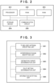
- FIG. 2 shows a hardware configuration example of the control device and the processing device.
- the Non-RT RIC 102 and the Near-RT RIC 103 may be realized as logical configurations, and functions of these RICs may be implemented in a single control device.
- the functions of the RICs may be implemented by a plurality of devices in a distributed manner.
- functions of the O-DU may be implemented using a single processing device or may be implemented using a plurality of devices in a distributed manner.
- control device and the processing device each include a processor 201, a ROM 202, a RAM 203, a storage device 204, and a communication circuit 205.
- the processor 201 executes a computer-readable program that is recorded in any of the ROM 202, the RAM 203, and the storage device 204, for example, and realizes the above-described functions of each device.
- the processor 201 may be replaced by one or more processors such as an ASIC (Application-Specific Integrated Circuit), an FPGA (Field Programmable Gate Array), a DSP (Digital Signal Processor), or the like.
- the processor 201 controls the communication circuit 205 to communicate with other devices, for example.
- the schematic diagram shown in FIG. 2 shows the control device or the processing device including a single communication circuit 205, but there is no limitation to this configuration.
- FIG. 3 shows a functional configuration example of the control device that functions as an RIC (at least either of the Non-RT RIC 102 and the Near-RT RIC 103). Functions shown in FIG. 3 are realized as a result of the processor 201 included in the control device executing a program stored in the ROM 202, the RAM 203, or the storage device 204, for example. Note that the control device may include hardware corresponding to at least any of the following functions. Note that FIG. 3 selectively shows functional units relating particularly to the present embodiment, among functions of the control device, and the control device naturally has common functions of RICs.
- the control device includes a to-be-used antenna specifying unit 301, an interference range identifying unit 302, an estimation target determination unit 303, a pilot setting determination unit 304, and an information notifying unit 305 as functional units, for example.
- the to-be-used antenna specifying unit 301 specifies, with respect to each terminal device, antennas that are to be used when providing a communication service to the terminal device among many antennas arranged over an area and each connected to any of O-DUs.
- the interference range identifying unit 302 identifies, with respect to each terminal device, antennas for which it is expected that a signal transmitted from the terminal device will interfere with communication relating to another terminal device at a sufficiently high power level. For example, based on the location of a terminal device, the interference range identifying unit 302 identifies a group of antennas that are expected to receive a signal transmitted from the terminal device with at least a predetermined power.
- the to-be-used antenna specifying unit 301 may specify, from the group of antennas, antennas that are near the location of the terminal device or for which it is expected that good radio quality will be obtained in communication with the terminal device, for example, as antennas to be used for communication relating to the terminal device.
- the to-be-used antenna specifying unit 301 may identify O-DUs to which the antennas used for communication relating to the terminal device are connected, and determine an O-DU to which the largest number of antennas used for the communication are connected, as an O-DU that executes communication processing for the terminal device including demodulation and decoding of signals, for example.
- the to-be-used antenna specifying unit 301 may select the O-DU that executes communication processing for the terminal device based on the state of loads on one or more O-DUs to which the antennas used for communication relating to the terminal device are connected, for example.
- the control device may notify, via the information notifying unit 305, for example, the O-DU that executes the communication processing of identification information of the terminal device that is the target of the communication processing and information regarding other O-DUs connected to the antennas used for communication relating to the terminal device. Also, the control device may notify the other O-DUs connected to the antennas used for communication relating to the terminal device of information specifying the antennas used for communication relating to the terminal device and information specifying the O-DU that executes communication processing for the terminal device.
- the to-be-used antenna specifying unit 301 and the interference range identifying unit 302 specify antennas with respect to each terminal device. For example, in the example shown in FIG. 1 , the interference range identifying unit 302 identifies the antennas 111 to 114 and the antennas 121 to 123 as a group of antennas that are expected to receive a signal transmitted from the terminal device 131 with at least a predetermined power based on the location of the terminal device 131. Also, the interference range identifying unit 302 identifies the antennas 122 to 124 as a group of antennas that are expected to receive a signal transmitted from the terminal device 132 with at least the predetermined power based on the location of the terminal device 132.
- the to-be-used antenna specifying unit 301 may specify, from the identified groups of antennas, the antennas 111 to 114 and the antennas 121 and 122 as antennas to be used for communication relating to the terminal device 131 and specify the antennas 122 to 124 as antennas to be used for communication relating to the terminal device 132.
- the estimation target determination unit 303 determines an O-DU that should perform transmission path estimation without executing communication processing for the terminal device, and antennas that are connected to the O-DU, based on antennas for which interference with communication relating to another terminal device is expected.
- an O-DU that does not perform communication processing for the terminal device may be determined as an O-DU that should execute transmission path estimation, and out of antennas connected to the O-DU, all antennas at which interference may occur may be determined as targets of the transmission path estimation performed with respect to the terminal device.
- interference from a signal transmitted from the terminal device 131 may occur at the antennas 121 to 123, and accordingly, it is possible to determine, as targets of the transmission path estimation performed with respect to the terminal device 131, only the antennas 122 and 123, which are included in both of the antennas 121 to 123 and the antennas 122 to 124 used for communication relating to the terminal device 132. In this case, O-DUs that do not perform communication processing for any of the terminal devices may not perform transmission path estimation.
- an O-DU such as the O-DU 105
- an O-DU such as the O-DU 105
- the O-DU 105 that is connected to one or more first antennas (the antennas 122 to 124) included in a plurality of antennas that are expected to receive a signal transmitted from a first terminal device (the terminal device 132) with at least a predetermined power and executes demodulation and decoding processing for the first terminal device
- the terminal device 132 the terminal device 132
- the terminal device 132 the terminal device 132
- the terminal device 132 the terminal device 132
- the terminal device 132 the terminal device 132
- the terminal device 132 the terminal device 132
- Such an O-DU is notified of information indicating the first antennas specified by the to-be-used antenna specifying unit 301 with respect to the first terminal device. Also, the O-DU is notified of information indicating one or more third antennas (e.g., the antennas 122 and 123) that are targets of the transmission path estimation among the second antennas identified by the interference range identifying unit 302 with respect to the second terminal, which is not the target of communication processing. Note that these types of information may be provided via the information notifying unit 305, for example. Note that the O-DU 105 may also be notified of information indicating one or more fourth antennas that are specified by the to-be-used antenna specifying unit 301 as antennas to be used for communication relating to the second terminal device.
- the O-DU 105 may also be notified of information indicating one or more fourth antennas that are specified by the to-be-used antenna specifying unit 301 as antennas to be used for communication relating to the second terminal device.
- the fourth antennas used for communication relating to the second terminal device are at least a portion of the one or more second antennas included in the plurality of antennas expected to receive a signal transmitted from the second terminal device with at least the predetermined power.
- the O-DU 105 shown in FIG. 1 is notified of information indicating the antennas 121 and 122, which are used for communication relating to the terminal device 131 and are a portion of the antennas 121 to 123 expected to receive a signal transmitted from the terminal device 131 with at least the predetermined power. Based on the notification, the O-DU 105 transfers signals received by the antennas 121 and 122 to the O-DU that executes communication processing for the terminal device 131.
- a signal received from the second terminal device (the terminal device 131) by a fifth antenna (e.g., the antenna 123) that does not belong to the fourth antennas (the antennas 121 and 122) among the second antennas (the antennas 121 to 123) is not transferred to the O-DU that executes communication processing for the second terminal device.
- the pilot setting determination unit 304 determines setting information regarding pilot symbols to be used for transmission path estimation by each terminal device.
- the setting information regarding pilot symbols includes information that makes it possible to identify a pilot symbol sequence to be transmitted from each terminal device, as described above.
- the information that makes it possible to identify a pilot symbol sequence may be the pilot symbol sequence itself or a value indicating any of indexes respectively assigned to pilot symbol sequence candidates in advance.
- the setting information regarding pilot symbols may include information that makes it possible to identify frequency and time resources that are used when the pilot symbols are transmitted.
- the information that makes it possible to identify frequency and time resources may be information directly specifying the frequency and time resources or information such as an index for specifying an allocation pattern to be used among a plurality of allocation patterns of frequency and time resources.
- the setting information regarding pilot symbols may include information that makes it possible to identify transmission power at the time when the pilot symbols are transmitted.
- the pilot setting determination unit 304 may also identify the number (density) of terminal devices present in an area in which the communication service can be provided via each of a plurality of antennas connected to an O-DU, and determine the sequence length of the pilot symbol sequence based on the number.
- the sequence length of the pilot symbol sequence may be set in such a manner that the sequence length increases as the density of terminal devices increases, and the sequence length decreases as the density of terminal devices decreases.
- sequence length may be determined through calculation by using a function and information indicating the density of terminal devices as an argument or may be determined by referring to a table in which a relationship between the density of terminal devices and the sequence length is defined, for example.
- the control device may notify a device functioning as the Near-RT RIC 103 or each O-DU of the determined sequence length via the information notifying unit 305.
- the pilot setting determination unit 304 may determine setting information to be used by each of the terminal devices in such a manner that the plurality of terminal devices do not use the same setting information regarding pilot symbols.
- the pilot setting determination unit 304 may determine setting information to be used by each terminal device in such a manner that the plurality of terminal devices do not transmit the same pilot symbol sequence using the same frequency and time resources.
- the control device may notify the O-DU that executes communication processing for each terminal device of the setting information determined as described above, and cause the O-DU to notify each terminal device of the setting information.
- the information notifying unit 305 notifies O-DUs or another control device (e.g., when the control device is a Non-RT RIC, a control device that functions as a Near-RT RIC) of the information determined or set by the above-described functional units.
- O-DUs O1 interface in the case where the control device is a Non-RT RIC
- E2 interface in the case where the control device is a Near-RT RIC
- information may be given to another control device that functions as a Near-RT RIC via the A1 interface.
- FIG. 4 shows a functional configuration example of the processing device that functions as an O-DU. Functions shown in FIG. 4 are realized as a result of the processor 201 included in the processing device executing a program stored in the ROM 202, the RAM 203, or the storage device 204, for example. Note that the processing device may include hardware corresponding to at least any of the following functions. Note that FIG. 4 selectively shows functional units relating particularly to the present embodiment, among functions of the processing device, and the processing device naturally has common functions of O-DUs.
- the processing device includes an information receiving unit 401, an estimation processing unit 402, a communication processing unit 403, and a received signal transfer unit 404 as functional units, for example.
- the information receiving unit 401 receives information given by the control device as described above. For example, when it is expected that an antenna that is connected to the processing device will receive a signal transmitted from a terminal device with at least a predetermined power, the information receiving unit 401 receives information in which the terminal device is associated with the antenna. For example, the information receiving unit 401 of the O-DU 105 may receive information in which the terminal device 131, which is not the target of communication processing, is associated with the antennas 121 to 123 and information in which the terminal device 132, which is the target of communication processing, is associated with the antennas 122 to 124.
- the information receiving unit 401 of the O-DU 105 may receive information in which the antennas 122 and 123 are associated with the terminal device 131. Also, the information receiving unit 401 may receive setting information regarding pilot symbols used by each terminal device when transmitting pilot symbols. For example, the information receiving unit 401 of the O-DU 105 receives setting information regarding pilot symbols for the terminal device 131 and the terminal device 132.
- the estimation processing unit 402 receives pilot symbols from a terminal device that is the target of transmission path estimation (not the target of communication processing) via antennas that are targets of transmission path estimation, and executes transmission path estimation based on the result of reception.
- the communication processing unit 403 executes interference suppressing control based on the MMSE criteria, for example, with respect to a signal received from a terminal device that is the target of communication processing, by using the result of transmission path estimation, and executes reception processing including demodulation and decoding of the signal subjected to the interference suppression.
- the received signal transfer unit 404 transfers a signal received via an antenna that is used for communication relating to a terminal device that is not the target of communication processing to an O-DU that executes communication processing for the terminal device, for example.
- FIG. 5 is a diagram showing an example flow of processing executed by the control device.
- the control device identifies, with respect to each of a plurality of terminal devices, for example, antennas that are expected to receive a signal transmitted from the terminal device with at least a predetermined power. Then, in an example, the control device may determine an O-DU that executes communication processing for each terminal device based on the identified antennas.
- the control device specifies antennas that are expected to receive a signal transmitted from a terminal device that is the target of communication processing, with at least the predetermined power, as targets of communication processing, and specifies antennas that are expected to receive a signal transmitted from a terminal device that is not the target of communication processing, with at least the predetermined power, as targets of transmission path estimation (S501). Then, the control device notifies each O-DU of antennas that are targets of communication processing and antennas that are targets of transmission path estimation for the O-DU (S502).
- each O-DU is notified of information in which antennas that are targets of communication processing are associated with a terminal device that is the target of communication processing and information in which antennas that are targets of transmission path estimation are associated with a terminal device that is the target of transmission path estimation.
- the control device notifies each O-DU of setting information regarding pilot symbols used by the terminal device that is the target of communication processing and setting information regarding pilot symbols used by the terminal device that is the target of transmission path estimation for the O-DU (S503).
- the control device may update setting information regarding pilot symbols to be used by each terminal device periodically or when it is determined that interference may occur between pilot symbols transmitted from a plurality of terminal devices, for example.
- FIG. 6 is a diagram showing an example flow of processing executed by the processing device.
- the processing device receives information that is transmitted from the control device in step S502, for example, and specifies antennas that are targets of communication processing and antennas that are targets of transmission path estimation for the processing device itself (S601). Also, the processing device receives setting information regarding pilot symbols used by a terminal device that is the target of communication processing and setting information regarding pilot symbols used by a terminal device that is the target of transmission path estimation (S602). Note that the processing device may perform setting processing regarding pilot symbols for the terminal device that is the target of communication processing, and in this case, the processing device may receive only setting information regarding pilot symbols used by the terminal device that is the target of transmission path estimation in step S602.
- each O-DU may execute transmission path estimation for all antennas connected to the O-DU with respect to each terminal device that is not the target of processing.
- antennas that are targets of transmission path estimation do not necessarily need to be specified, and the processing in steps S501, S502, and S601 may be omitted, for example.
- the processing in steps S501, S502, and S601 is performed, antennas for which transmission path estimation is executed are limited, and therefore, it is possible to save computing resources of the O-DU.
- each O-DU may execute transmission path estimation by using all possible setting information regarding pilot symbols.
- the O-DU need not obtain setting information regarding pilot symbols used by each terminal device, and therefore, the processing in steps S503 and S602 may be omitted, for example.
- the processing in steps S503 and S602 is performed, transmission path estimation can be executed using limited setting information, and therefore, it is possible to save computing resources of the O-DU.
- a processing device can perform communication relating to a terminal device that is the target of communication processing for the processing device itself at high efficiency by suppressing interference from a terminal device that is the target of communication processing performed by another processing device. Therefore, it is possible to contribute to achieving the Goal 9 "Build resilient infrastructure, promote sustainable industrialization and foster innovation.” of the Sustainable Development Goals (SDGs) promoted by the United Nations.
- SDGs Sustainable Development Goals
Landscapes
- Engineering & Computer Science (AREA)
- Signal Processing (AREA)
- Computer Networks & Wireless Communication (AREA)
- Quality & Reliability (AREA)
- Mobile Radio Communication Systems (AREA)
Abstract
Description
- The present invention relates to a technology for improving a communication efficiency in a cell-free massive MIMO system composed of many antennas.
- Studies have been made on cell-free massive MIMO systems in which many antennas are arranged densely and communication with a terminal device is performed using a portion of the antennas. In such a cell-free massive MIMO system, antennas to be used are selected for each terminal device, and thus a cell is virtually configured for each terminal device, and a terminal device is located substantially at the center of a virtual cell. According to this technology, each terminal device can obtain uniform communication quality irrespective of its location.
- In such a cell-free massive MIMO system, a processing device connected to antennas forms a virtual cell for each terminal device by controlling those antennas. In such a system, the number of antennas and terminal devices is enormous, and therefore, it is not easy to control the system with use of a single processing device. Accordingly, a configuration is contemplated in which a plurality of processing devices each configured to control a portion of the antennas are prepared, and each terminal device performs communication by establishing connection with any of the processing devices. When this configuration is used, if a terminal device is present at a position around an end portion of an area in which communication can be performed using antennas controlled by a processing device to which the terminal device has been connected, another processing device controlling antennas forming an area that allows communication at that position may be involved in communication performed by the terminal device. For example, the other processing device may receive a signal transmitted from the terminal device and transfer the signal to the processing device to which the terminal device has been connected, and the processing device may perform signal processing such as demodulation by using signals received by antennas connected to the processing device itself and the transferred signal (NPL 1).
- NPL1: C. D' Andrea and E. G. Larsson, "User association in scalable cell-free massive MIMO systems", 2020 54th Asilomar Conference on Signals, Systems, and Computers, 2020
- In the technique described in NPL 1, a signal received by an antenna controlled by the other processing device to which the terminal device is not connected is transferred to the processing device to which the terminal device has been connected, but no consideration is given to the influence on communication performed by another terminal device that has been connected to the other processing device. Accordingly, communication performed by a terminal device connected to a processing device may interfere with another terminal device connected to another processing device, and the efficiency of the system as a whole may deteriorate.
- The present invention provides a technology for improving a communication efficiency in a cell-free massive MIMO system including a plurality of processing devices connected to one or more antennas.
- A control device according to one aspect of the present invention is a control device that functions as a RAN Intelligent Controller (RIC) in an Open-Radio Access Network (O-RAN), the control device comprising: identification means for identifying, with respect to each of a plurality of terminal devices, a plurality of antennas that are expected to receive, with at least a predetermined power, a signal transmitted from the terminal device, based on locations of the plurality of terminal devices; and notification means for notifying an O-RAN Distributed Unit (O-DU) that is connected to one or more first antennas included in the plurality of antennas for a first terminal device and executes demodulation and decoding processing for the first terminal device, and is connected to one or more second antennas included in the plurality of antennas for a second terminal device and does not execute demodulation and decoding processing for the second terminal device, of information indicating the one or more first antennas and information indicating a third antenna among the one or more second antennas, the third antenna being a target of transmission path estimation performed based on pilot symbols received from the second terminal device.
- A processing device according to one aspect of the present invention is a processing device that functions as an O-RAN Distributed Unit (O-DU) connected to a plurality of antennas to perform radio communication with a terminal device in an Open-Radio Access Network (O-RAN), the processing device comprising: receiving means for receiving information indicating one or more first antennas that receive a signal transmitted from a first terminal device that is a target of signal demodulation and decoding processing, among the plurality of antennas, and information indicating a third antenna among one or more second antennas that receive a signal transmitted from a second terminal device that is not a target of signal demodulation and decoding processing, among the plurality of antennas, the third antenna being a target of transmission path estimation performed based on pilot symbols received from the second terminal device; estimation means for estimating a transmission path between the third antenna and the second terminal device; and execution means for executing communication processing for the first terminal device by using a result of the transmission path estimation.
- According to the present invention, it is possible to improve a communication efficiency in a cell-free massive MIMO system including a plurality of processing devices connected to one or more antennas.
- Other features and advantages of the present invention will be apparent from the following description taken in conjunction with the accompanying drawings. Note that the same reference numerals denote the same or like components throughout the accompanying drawings.
- The accompanying drawings, which are incorporated in and constitute a part of the specification, illustrate embodiments of the invention and, together with the description, serve to explain principles of the invention.
-
FIG. 1 is a diagram showing a configuration example of a radio communication system. -
FIG. 2 is a diagram showing a hardware configuration example of a device. -
FIG. 3 is a diagram showing a functional configuration example of a control device. -
FIG. 4 is a diagram showing a functional configuration example of a processing device. -
FIG. 5 is a diagram showing an example flow of processing executed by the control device. -
FIG. 6 is a diagram showing an example flow of processing executed by the processing device. - Hereinafter, embodiments will be described in detail with reference to the attached drawings. Note, the following embodiments are not intended to limit the scope of the claimed invention, and limitation is not made to an invention that requires a combination of all features described in the embodiments. Two or more of the multiple features described in the embodiments may be combined as appropriate. Furthermore, the same reference numerals are given to the same or similar configurations, and redundant description thereof is omitted.
-
FIG. 1 shows a configuration example of a radio communication system according to the present embodiment. The radio communication system is a cell-free massive MIMO system in which many antennas (e.g.,antennas 111 to 114 andantennas 121 to 124) are geographically distributed and a radio communication service is provided to terminal devices (e.g., a terminal device 131 and a terminal device 132) by forming a virtual cell for each terminal device with use of a portion of the antennas. In the present embodiment, many antennas are divided into a plurality of groups, the groups are respectively connected to different processing devices, and the processing devices control antenna weights, perform encoding and modulation of signals to be transmitted by the antennas, and demodulation and decoding of signals received by the antennas, for example. Note that such a processing device may be called a central processing unit (CPU), for example. Note that a virtual CPU may be set for each terminal device, and the virtual CPU may execute communication processing for the corresponding terminal device. Such a virtual CPU may also be called a vCPU. The antennas may be antennas that have a function of capturing electromagnetic waves or radiating electromagnetic waves, or communication devices that have a function of executing certain processing such as frequency conversion or amplification, for example. Such antennas may be called "access points (AP)", for example. - In an example, the radio communication system according to the present embodiment is configured using Open-Radio Access Network (O-RAN), standardization of which is promoted to make radio access networks (RANs) open and intelligent. According to the O-RAN, a RAN is made intelligent by controlling a plurality of O-DUs (E2 nodes) connected to terminal devices with use of control devices that are called RAN Intelligent Controllers (RICs). Note that O-DU is abbreviation for O-RAN Distributed Unit, and an O-DU as used herein corresponds to a processing device directly connected to antennas. Here, the
antennas 111 to 114 are connected to an O-DU 104, and theantennas 121 to 124 are connected to an O-DU 105. Note that these are examples, and the RICs include a Near-RT RIC 103 that performs short period control in substantially real time (RT) and aNon-RT RIC 102 that performs long period control not in real time. Note that the Non-RT RIC 102 is configured as a portion of Service Management and Orchestration (SMO 101). - The Non-RT RIC 102 performs long term control such as RAN analysis and policy management. The Near-
RT RIC 103 controls O-DUs in accordance with policies determined by theNon-RT RIC 102. Note that an interface called "O1 interface" is set between the Non-RT RIC 102 (SMO 101) and the O-DUs, an A1 interface is set between theNon-RT RIC 102 and the Near-RT RIC 103, and an E2 interface is set between the Near-RT RIC 013 and the O-DUs. Note that an interface (not shown) that enables direct communication between an O-DU and another O-DU may be prepared between the O-DUs. - In the present embodiment, it is assumed that the terminal device 131 is located near the boundary between an area in which communication can be performed via the
antennas 111 to 114 and an area in which communication can be performed via theantennas antennas 111 to 114 and theantennas antennas 111 to 114 and theantennas DU 104 executes communication processing for the terminal device 131, for example, the signal received by theantennas 121 and 122 (e.g., an IQ signal subjected to frequency conversion to baseband and sampling) may be transferred from the O-DU 105 to the O-DU 104. The O-DU 104 may demodulate and decode the signal transmitted from the terminal device 131 by using the signal received via theantennas 111 to 114 and the signal received via theantennas DU 104 and the O-DU 105, and transmitted from theantennas 111 to 114 and theantennas antennas DU 104, for example. In this case, signals in forms in which theantennas DU 104 to the O-DU 105. Then, the O-DU 105 converts the received signals to RF signals that can be transmitted from antennas, and performs control so that the signals will be respectively output from theantennas - It is assumed that, on the other hand, the terminal device 132 is present in a region in which communication can be performed with use of the
antennas 122 to 124 connected to the O-DU 105. In this case, the terminal device 132 may perform communication via theantennas 122 to 124. Note that the terminal device 132 is not located within an area in which communication can be performed with use of antennas connected to other O-DUs. - In the present embodiment, the
Non-RT RIC 102 or the Near-RT RIC 103 determines O-DUs that execute communication processing relating to the terminal devices 131 and 132 based on locations of the terminal devices 131 and 132, for example. For example, theNon-RT RIC 102 or the Near-RT RIC 103 determines to execute communication processing for the terminal device 131 with use of the O-DU 104 and execute communication processing for the terminal device 132 with use of the O-DU 105. Then, theNon-RT RIC 102 or the Near-RT RIC 103 may instruct the O-DU 104 to boot a vCPU for communication processing for the terminal device 131 and instruct the O-DU 105 to boot a vCPU for communication processing for the terminal device 132 in accordance with the determination. Note that theNon-RT RIC 102 or the Near-RT RIC 103 identifies antennas that are to be used in communication for each terminal device, and transmits an instruction to each O-DU so that processing will be performed in accordance with the result of identification. For example, theNon-RT RIC 102 or the Near-RT RIC 103 may instruct the O-DU 105 to transfer signals received by theantennas DU 104 for communication relating to the terminal device 131. Also, theNon-RT RIC 102 or the Near-RT RIC 103 may instruct the O-DU 104 to transmit, to the O-DU 105, signals to be transmitted from theantennas DU 104 and the terminal device 132 has been connected to the O-DU 105. - Note that the
Non-RT RIC 102 may determine a long-term policy, and the Near-RT RIC 103 may be configured to control O-DUs in accordance with the long-term policy. In this case, theNon-RT RIC 102 may notify the Near-RT RIC 103 of a policy based on which the Near-RT RIC 103 determines O-DUs to which terminal devices are to be respectively connected. Then, the Near-RT RIC 103 may determine O-DUs to which the terminal devices are to be respectively connected (O-DUs to be caused to boot vCPUs for communication processing for the respective terminal devices) in accordance with the policy, and control the O-DUs based on the result of determination. Also, the Near-RT RIC 103 may select antennas that are to be used in communication relating to each terminal device, and control the O-DUs to execute data transfer and the like in accordance with the result of selection. - It is assumed that, in the above-described configuration, communication processing for the terminal device 131 is executed by the O-
DU 104, and communication processing for the terminal device 132 is executed by the O-DU 105. That is, the O-DU 104 boots a vCPU for the terminal device 131, and the O-DU 105 boots a vCPU for the terminal device 131. Here, the terminal device 131 performs communication not only via theantennas 111 to 114 but also via theantennas DU 104. That is, a signal transmitted by the terminal device 131 and received via theantennas DU 105 and is transferred as is to the O-DU 104. Accordingly, the vCPU that executes communication processing for the terminal device 132 in the O-DU 105 cannot recognize characteristics of the signal transmitted from the terminal device 131 and reduce the influence of interference from the signal transmitted from the terminal device 131 when demodulating and decoding a signal transmitted from the terminal device 132. Here, if the O-DU 105 is notified of a result of estimation of transmission paths between the terminal device 131 and theantennas DU 104, for example, the vCPU of the O-DU 105 can reduce the influence of interference from the signal transmitted from the terminal device 131 by using the estimated values of transmission paths. However, in this case, the amount of information that need to be transmitted and received between the O-DU 104 and the O-DU 105 increases, and particularly when many terminal devices are present near the boundary between areas controlled by a plurality of O-DUs, like the terminal device 131, such information may take up a large proportion of the capacity of backhaul link. Also, a signal transmitted from the terminal device 131 may reach theantenna 123, which is not used for the communication, for example, but the O-DU 104 does not execute processing relating to theantenna 123, and therefore, it is not possible to reduce the influence of interference at theantenna 123. - Under the above circumstances, in the present embodiment, even when an O-DU connected to an antenna that is used for communication relating to a terminal device does not execute communication processing for the terminal device, a vCPU associated with the terminal device is set in the O-DU. Then, the vCPU executes processing for suppressing interference, such as transmission path estimation, with respect to a signal transmitted from the terminal device for which the O-DU does not execute communication processing, and provides information obtained through the processing to a vCPU that is set to perform communication relating to another terminal device with use of the same antenna as that used by the terminal device. Then, the vCPU set for the communication relating to the other terminal device executes interference suppressing control (e.g., beam control) based on the provided information. For example, not only the vCPU for communication relating to the terminal device 132, for which the O-
DU 105 executes communication processing, but also a vCPU associated with the terminal device 131, for which the O-DU 105 does not execute communication processing, is set in the O-DU 105. Then, the vCPU associated with the terminal device 131 in the O-DU 105 estimates transmission paths between theantennas 121 to 123 and the terminal device 131, for example, and provides the result of transmission path estimation to the vCPU for communication relating to the terminal device 132. Note that, in an example, the vCPU associated with the terminal device 131 in the O-DU 105 is configured to execute only processing (e.g., transmission path estimation) that is necessary to suppress interference and so as not to be involved in communication relating to the terminal device 131. Based on this information, the vCPU for communication relating to the terminal device 132 can calculate antenna weights for theantennas 122 to 124 in accordance with the minimum mean squared error (MMSE) criteria, for example, and reduce interference from a signal transmitted from the terminal device 131. - In the present embodiment, in order to realize the above-described processing, the
Non-RT RIC 102 or the Near-RT RIC 103 provides the O-DU 104 and the O-DU 105 with information that enables the O-DUs to execute the above-described processing. For example, theNon-RT RIC 102 or the Near-RT RIC 103 may notify the O-DU 104 and the O-DU 105 of pilot allocation information regarding each terminal device. Note that the pilot allocation information may be information that makes it possible to identify positions of frequency and time resources in which pilot symbols are transmitted from the terminal device 131 and a pilot symbol sequence, for example. In a case where the frequency and time resources in which pilot symbols are transmitted are fixed, for example, information indicating the positions of the frequency and time resources does not necessarily need to be included in the pilot allocation information. Also, in a case where the frequency and time resources in which pilot symbols are transmitted can be identified based on the sequence length of the pilot symbol sequence, for example, information indicating the positions of the frequency and time resources may be implicitly provided as the sequence length. Also, in a case where the positions of the frequency and time resources can be identified based on another parameter, the parameter may be provided. Also, information indicating transmission power at the time when pilot symbols are transmitted by the terminal device may be provided in addition to the pilot allocation information. In a case where the transmission power of pilot symbols is constant, information indicating the transmission power does not necessarily need to be provided. In a case where the transmission power of pilot symbols is determined based on a category of the terminal device or the like, suitable information, such as the category, that makes it possible to identify the transmission power may be provided. That is, setting information regarding pilot symbols for a terminal device may be provided to an O-DU that executes communication processing for the terminal device and an O-DU that executes communication processing for another terminal device that is expected to be interfered by a signal transmitted from the terminal device. According to this configuration, the O-DU 105 can obtain pilot allocation information regarding the terminal device 131 and estimate transmission paths between the terminal device 131 and theantennas 121 to 123 based on signals received from the terminal device 131 by theantennas 121 to 123, for example. In the following description, the pilot allocation information may be read as setting information regarding pilot symbols, unless otherwise stated. - Note that a pilot allocation to be used by each terminal device may be determined by the
Non-RT RIC 102 or the Near-RT RIC 103. Also, theNon-RT RIC 102 or the Near-RT RIC 103 determines antennas to be used for communication relating to each terminal device as described above. Accordingly, theNon-RT RIC 102 or the Near-RT RIC 103 can identify not only an O-DU that executes communication processing for a terminal device, but also one or more O-DUs that are connected to antennas used for communication relating to the terminal device, and the one or more O-DUs may be notified of a pilot symbol sequence and frequency and time resources allocated to the terminal device. Note that a pilot allocation to be used by each terminal device may be determined by an O-DU that executes communication processing for the terminal device. In this case, information indicating the allocation may be given to the Near-RT RIC 103 or theNon-RT RIC 102, and may be given from the Near-RT RIC 103 or theNon-RT RIC 102 to other O-DUs that are connected to antennas used for communication relating to the terminal device. Note that a configuration is also possible in which theNon-RT RIC 102 or the Near-RT RIC 103 determines pilot allocation candidates that can be used at each O-DU, and each O-DU selects, from the candidates, a pilot allocation to be actually used by a terminal device for which the O-DU executes communication processing, for example. According to this configuration, by assigning different candidates to a plurality of O-DUs corresponding to adjacent areas, it is possible to prevent terminal devices connected to the adjacent O-DUs from using the same pilot allocation, and thus prevent deterioration in the precision of transmission path estimation. - As described above, different sequences may be set for respective terminal devices in pilot allocation. However, the number of sequences may become insufficient due to an increase in the number of terminal devices, and there may be a case where two or more terminal devices use the same sequence. Therefore, in a situation in which the number of terminal devices present in a certain area increases, for example, the
Non-RT RIC 102 or the Near-RT RIC 103 may determine to increase the sequence length of pilot symbol sequences to be used by terminal devices present in that area. When the sequence length of pilot symbol sequences is increased, it is possible to prepare many sequence candidates that are orthogonal to each other and can be used as pilot symbol sequences, and precisely execute transmission path estimation based on signals received from each terminal device. On the other hand, in a situation in which the number of terminal devices present in a certain area decreases, for example, theNon-RT RIC 102 or the Near-RT RIC 103 may reduce the sequence length of pilot symbol sequences. In this case, it is possible to reduce frequency and time resources required for transmitting the pilot symbol sequences, and increase frequency and time resources that can be used to transmit and receive user data. In an example, theNon-RT RIC 102 or the Near-RT RIC 103 may identify the density of terminal devices in each of areas corresponding to respective O-DUs, and determine the sequence length of pilot symbol sequences to be used by terminal devices connected to an O-DU by referring to a table in which a relationship between the density and the sequence length of pilot symbol sequences is defined in advance or by inputting a value indicating the density, as an argument to a predetermined function. Then, theNon-RT RIC 102 or the Near-RT RIC 103 may notify the O-DU of policy information indicating that the sequence length of pilot symbol sequences should be increased. - In an example, the
Non-RT RIC 102 identifies an area for which it is expected that the density of terminal devices will increase in a long period based on a history regarding the number of terminal devices present in each area and information indicating events or the like. Then, theNon-RT RIC 102 may determine to increase the sequence length of pilot symbol sequences, as a long-term policy for that area. Also, theNon-RT RIC 102 identifies an area for which it is expected that the density of terminal devices will decrease in a long period, and may determine to reduce the sequence length of pilot symbol sequences, as a long-term policy for that area. For example, theNon-RT RIC 102 identifies, as a density, the number of terminal devices present in each of areas in which a communication service is provided via respective antennas, determines the sequence length according to the density, and generates policy information including information that makes it possible to identify the determined sequence length. In an example, the number (density) of terminal devices may be identified as described above with respect to each of a plurality of antennas, and the sequence length may be determined based on the largest number among the numbers of terminal devices corresponding to the respective antennas. Note that the sequence length may be applied to an area in which the communication service can be provided via the antenna corresponding to the largest number of terminal devices and another area that overlaps at least partially with that area, for example. TheNon-RT RIC 102 may notify at least either the Near-RT RIC 103 or O-DUs of this policy information. Note that the policy information may indicate the sequence length to be used or indicate that the currently used sequence length should be increased or reduced. - In the case where the Near-
RT RIC 103 is notified of this policy information, the Near-RT RIC 103 determines the sequence length of pilot symbol sequences to be used by terminal devices controlled by each O-DU based on the policy information, generates short-term policy information, and notifies each O-DU of the policy information. Note that the short-term policy information may include information indicating the sequence length of pilot symbol sequences or information indicating that the sequence length should be increased or reduced. - Each O-DU may receive long-term policy information from the
Non-RT RIC 102 or short-term policy information from the Near-RT RIC 103, and allocate a pilot symbol sequence having the sequence length specified by the policy information to a terminal device connected to the O-DU. Note that the pilot symbol sequence allocated to each terminal device may be determined by theNon-RT RIC 102 or the Near-RT RIC 103. Alternatively, theNon-RT RIC 102 or the Near-RT RIC 103 may determine sequence candidates that can be used at each O-DU among pilot symbol sequences having the determined sequence length, and notify each O-DU of information indicating the candidates. Then, each O-DU may select a pilot symbol sequence from the candidates, and allocate the selected pilot symbol sequence to a terminal device connected to the O-DU. In this case, the O-DU may notify another O-DU of information regarding pilot symbols (the sequence and frequency and time resources to be used) allocated to each terminal device via the Near-RT RIC 103. - Note that there may be a case where signals transmitted from terminal devices that use the same pilot symbol sequence reach the same antenna in the network as a result of a terminal device having moved. Therefore, the Near-
RT RIC 103 may monitor the location of each terminal device, for example, so that different pilot allocation will be performed with respect to terminal devices present in an area corresponding to each antenna of each O-DU. For example, the Near-RT RIC 103 may update pilot allocation so that pilot symbol sequences and frequency and time resources used to transmit pilot symbols allocated to respective terminal devices present in an area corresponding to each antenna do not match. When the Near-RT RIC 103 has updated pilot allocation with respect to a terminal device, the Near-RT RIC 103 notifies O-DUs connected to antennas corresponding to the location of the terminal device of the updated allocation. Note that the antennas corresponding to the location of the terminal device are antennas that may receive a signal transmitted from the terminal device with power of at least a predetermined level, and are not limited to antennas that are actually used for communication with the terminal device. That is, not only an O-DU that boots a vCPU for executing communication processing for the terminal device, but also all O-DUs that boot vCPUs for executing processing for suppressing interference as described above are notified of information indicating the pilot allocation. When pilot allocation is performed by the Near-RT RIC 103 as described above with respect to terminal devices present in a wide area, it is possible to prevent a situation in which a plurality of terminal devices use a common pilot allocation with respect to the same antenna even when any of the terminal devices has moved, and it is possible to prevent deterioration in the precision of transmission path estimation. - Note that the
Non-RT RIC 102 or the Near-RT RIC 103 may notify each O-DU of information indicating an antenna via which pilot symbols to be used for transmission path estimation are to be received, with respect to each terminal device. For example, in the state shown inFIG. 1 , theNon-RT RIC 102 or the Near-RT RIC 103 may notify the O-DU105 that transmission path estimation for the terminal device 131 should be performed using pilot symbols received via theantennas antenna 121 may receive a signal from the terminal device 131 with a sufficiently strong power level, but the signal does not affect communication relating to the terminal device 132, and therefore, it can be determined that there is no need to estimate the transmission path. As described above, the O-DU 105 may be notified of information indicating that transmission path estimation should be performed only with respect to antennas at which non-negligible interference may occur on communication relating to the terminal device 132. According to this configuration, the O-DU 105 can be kept from performing transmission path estimation for the terminal device 131 with respect to theantennas antenna 124, which is not affected by communication relating to the terminal device 131 or is affected at a sufficiently low level, and therefore, it is possible to suppress consumption of computation resources in the O-DU 105. - Next, the following describes configurations of a control device (at least either of the
Non-RT RIC 102 and the Near-RT RIC 103) and a processing device (O-DU).FIG. 2 shows a hardware configuration example of the control device and the processing device. Note that theNon-RT RIC 102 and the Near-RT RIC 103 may be realized as logical configurations, and functions of these RICs may be implemented in a single control device. Alternatively, the functions of the RICs may be implemented by a plurality of devices in a distributed manner. Also, functions of the O-DU may be implemented using a single processing device or may be implemented using a plurality of devices in a distributed manner. - In an example, the control device and the processing device each include a
processor 201, aROM 202, aRAM 203, astorage device 204, and acommunication circuit 205. In the control device and the processing device, theprocessor 201 executes a computer-readable program that is recorded in any of theROM 202, theRAM 203, and thestorage device 204, for example, and realizes the above-described functions of each device. Note that theprocessor 201 may be replaced by one or more processors such as an ASIC (Application-Specific Integrated Circuit), an FPGA (Field Programmable Gate Array), a DSP (Digital Signal Processor), or the like. In the control device and the processing device, theprocessor 201 controls thecommunication circuit 205 to communicate with other devices, for example. The schematic diagram shown inFIG. 2 shows the control device or the processing device including asingle communication circuit 205, but there is no limitation to this configuration. -
FIG. 3 shows a functional configuration example of the control device that functions as an RIC (at least either of theNon-RT RIC 102 and the Near-RT RIC 103). Functions shown inFIG. 3 are realized as a result of theprocessor 201 included in the control device executing a program stored in theROM 202, theRAM 203, or thestorage device 204, for example. Note that the control device may include hardware corresponding to at least any of the following functions. Note thatFIG. 3 selectively shows functional units relating particularly to the present embodiment, among functions of the control device, and the control device naturally has common functions of RICs. The control device includes a to-be-usedantenna specifying unit 301, an interferencerange identifying unit 302, an estimationtarget determination unit 303, a pilotsetting determination unit 304, and aninformation notifying unit 305 as functional units, for example. - The to-be-used
antenna specifying unit 301 specifies, with respect to each terminal device, antennas that are to be used when providing a communication service to the terminal device among many antennas arranged over an area and each connected to any of O-DUs. The interferencerange identifying unit 302 identifies, with respect to each terminal device, antennas for which it is expected that a signal transmitted from the terminal device will interfere with communication relating to another terminal device at a sufficiently high power level. For example, based on the location of a terminal device, the interferencerange identifying unit 302 identifies a group of antennas that are expected to receive a signal transmitted from the terminal device with at least a predetermined power. Then, the to-be-usedantenna specifying unit 301 may specify, from the group of antennas, antennas that are near the location of the terminal device or for which it is expected that good radio quality will be obtained in communication with the terminal device, for example, as antennas to be used for communication relating to the terminal device. - Note that the to-be-used
antenna specifying unit 301 may identify O-DUs to which the antennas used for communication relating to the terminal device are connected, and determine an O-DU to which the largest number of antennas used for the communication are connected, as an O-DU that executes communication processing for the terminal device including demodulation and decoding of signals, for example. Alternatively, the to-be-usedantenna specifying unit 301 may select the O-DU that executes communication processing for the terminal device based on the state of loads on one or more O-DUs to which the antennas used for communication relating to the terminal device are connected, for example. Then, the control device may notify, via theinformation notifying unit 305, for example, the O-DU that executes the communication processing of identification information of the terminal device that is the target of the communication processing and information regarding other O-DUs connected to the antennas used for communication relating to the terminal device. Also, the control device may notify the other O-DUs connected to the antennas used for communication relating to the terminal device of information specifying the antennas used for communication relating to the terminal device and information specifying the O-DU that executes communication processing for the terminal device. - Note that the to-be-used
antenna specifying unit 301 and the interferencerange identifying unit 302 specify antennas with respect to each terminal device. For example, in the example shown inFIG. 1 , the interferencerange identifying unit 302 identifies theantennas 111 to 114 and theantennas 121 to 123 as a group of antennas that are expected to receive a signal transmitted from the terminal device 131 with at least a predetermined power based on the location of the terminal device 131. Also, the interferencerange identifying unit 302 identifies theantennas 122 to 124 as a group of antennas that are expected to receive a signal transmitted from the terminal device 132 with at least the predetermined power based on the location of the terminal device 132. The to-be-usedantenna specifying unit 301 may specify, from the identified groups of antennas, theantennas 111 to 114 and theantennas antennas 122 to 124 as antennas to be used for communication relating to the terminal device 132. - With respect to each terminal device for which the identification of antennas has been performed by the interference
range identifying unit 302, the estimationtarget determination unit 303 determines an O-DU that should perform transmission path estimation without executing communication processing for the terminal device, and antennas that are connected to the O-DU, based on antennas for which interference with communication relating to another terminal device is expected. For example, when communication performed by the terminal device 131 may interference with communication performed by another terminal device at theantennas 111 to 114 and theantennas 121 to 123, and the O-DU 104 executes communication processing for the terminal device 131, the estimationtarget determination unit 303 may determine to cause the O-DU 105 connected to theantennas 121 to 123 at which interference may occur, to perform transmission path estimation, out of O-DUs that do not perform communication processing for the terminal device 131. Also, the estimationtarget determination unit 303 may determine all of theantennas 121 to 123 at which interference may occur, as targets of the transmission path estimation performed with respect to the terminal device 131, out of the antennas connected to the O-DU 105, for example. That is, in an example, out of O-DUs connected to antennas at which interference from a signal transmitted from a terminal device may occur, an O-DU that does not perform communication processing for the terminal device may be determined as an O-DU that should execute transmission path estimation, and out of antennas connected to the O-DU, all antennas at which interference may occur may be determined as targets of the transmission path estimation performed with respect to the terminal device. Note that this is an example, and a configuration is also possible in which, out of theantennas 121 to 124 connected to the O-DU 105, only theantennas 122 to 124 used for communication relating to the terminal device 132, which is the target of communication processing performed by the O-DU 105, may be determined as targets of the transmission path estimation performed with respect to the terminal device 131, for example. In this case, interference from a signal transmitted from the terminal device 131 may occur at theantennas 121 to 123, and accordingly, it is possible to determine, as targets of the transmission path estimation performed with respect to the terminal device 131, only theantennas antennas 121 to 123 and theantennas 122 to 124 used for communication relating to the terminal device 132. In this case, O-DUs that do not perform communication processing for any of the terminal devices may not perform transmission path estimation. - In general, with respect to an O-DU, such as the O-
DU 105, that is connected to one or more first antennas (theantennas 122 to 124) included in a plurality of antennas that are expected to receive a signal transmitted from a first terminal device (the terminal device 132) with at least a predetermined power and executes demodulation and decoding processing for the first terminal device, and is connected to one or more second antennas (theantennas 121 to 123) included in a plurality of antennas (theantennas 111 to 114 andantennas 121 to 123) that are expected to receive a signal transmitted from a second terminal device (the terminal device 131) with at least the predetermined power and does not execute demodulation and decoding processing for the second terminal device, it is determined to cause the O-DU to only perform transmission path estimation without executing communication processing like that described above. Such an O-DU is notified of information indicating the first antennas specified by the to-be-usedantenna specifying unit 301 with respect to the first terminal device. Also, the O-DU is notified of information indicating one or more third antennas (e.g., theantennas 122 and 123) that are targets of the transmission path estimation among the second antennas identified by the interferencerange identifying unit 302 with respect to the second terminal, which is not the target of communication processing. Note that these types of information may be provided via theinformation notifying unit 305, for example. Note that the O-DU 105 may also be notified of information indicating one or more fourth antennas that are specified by the to-be-usedantenna specifying unit 301 as antennas to be used for communication relating to the second terminal device. Note that the fourth antennas used for communication relating to the second terminal device are at least a portion of the one or more second antennas included in the plurality of antennas expected to receive a signal transmitted from the second terminal device with at least the predetermined power. For example, the O-DU 105 shown inFIG. 1 is notified of information indicating theantennas antennas 121 to 123 expected to receive a signal transmitted from the terminal device 131 with at least the predetermined power. Based on the notification, the O-DU 105 transfers signals received by theantennas antennas 121 and 122) among the second antennas (theantennas 121 to 123) is not transferred to the O-DU that executes communication processing for the second terminal device. - The pilot
setting determination unit 304 determines setting information regarding pilot symbols to be used for transmission path estimation by each terminal device. The setting information regarding pilot symbols includes information that makes it possible to identify a pilot symbol sequence to be transmitted from each terminal device, as described above. In an example, the information that makes it possible to identify a pilot symbol sequence may be the pilot symbol sequence itself or a value indicating any of indexes respectively assigned to pilot symbol sequence candidates in advance. Also, the setting information regarding pilot symbols may include information that makes it possible to identify frequency and time resources that are used when the pilot symbols are transmitted. The information that makes it possible to identify frequency and time resources may be information directly specifying the frequency and time resources or information such as an index for specifying an allocation pattern to be used among a plurality of allocation patterns of frequency and time resources. Also, the setting information regarding pilot symbols may include information that makes it possible to identify transmission power at the time when the pilot symbols are transmitted. - Note that in the case where the control device has the functions of the
Non-RT RIC 102, the pilot settingdetermination unit 304 may also identify the number (density) of terminal devices present in an area in which the communication service can be provided via each of a plurality of antennas connected to an O-DU, and determine the sequence length of the pilot symbol sequence based on the number. For example, the sequence length of the pilot symbol sequence may be set in such a manner that the sequence length increases as the density of terminal devices increases, and the sequence length decreases as the density of terminal devices decreases. Note that the sequence length may be determined through calculation by using a function and information indicating the density of terminal devices as an argument or may be determined by referring to a table in which a relationship between the density of terminal devices and the sequence length is defined, for example. The control device may notify a device functioning as the Near-RT RIC 103 or each O-DU of the determined sequence length via theinformation notifying unit 305. - Note that in the case where the control device has the functions of the Near-
RT RIC 103 and when it is expected that signals transmitted from a plurality of terminal devices will be received by a common antenna based on the locations of the terminal devices, for example, the pilot settingdetermination unit 304 may determine setting information to be used by each of the terminal devices in such a manner that the plurality of terminal devices do not use the same setting information regarding pilot symbols. In particular, the pilot settingdetermination unit 304 may determine setting information to be used by each terminal device in such a manner that the plurality of terminal devices do not transmit the same pilot symbol sequence using the same frequency and time resources. The control device may notify the O-DU that executes communication processing for each terminal device of the setting information determined as described above, and cause the O-DU to notify each terminal device of the setting information. - The
information notifying unit 305 notifies O-DUs or another control device (e.g., when the control device is a Non-RT RIC, a control device that functions as a Near-RT RIC) of the information determined or set by the above-described functional units. Note that information is given to O-DUs via the O1 interface in the case where the control device is a Non-RT RIC, and via the E2 interface in the case where the control device is a Near-RT RIC. Also, in the case where the control device is a Non-RT RIC, information may be given to another control device that functions as a Near-RT RIC via the A1 interface. -
FIG. 4 shows a functional configuration example of the processing device that functions as an O-DU. Functions shown inFIG. 4 are realized as a result of theprocessor 201 included in the processing device executing a program stored in theROM 202, theRAM 203, or thestorage device 204, for example. Note that the processing device may include hardware corresponding to at least any of the following functions. Note thatFIG. 4 selectively shows functional units relating particularly to the present embodiment, among functions of the processing device, and the processing device naturally has common functions of O-DUs. The processing device includes aninformation receiving unit 401, anestimation processing unit 402, acommunication processing unit 403, and a receivedsignal transfer unit 404 as functional units, for example. - The
information receiving unit 401 receives information given by the control device as described above. For example, when it is expected that an antenna that is connected to the processing device will receive a signal transmitted from a terminal device with at least a predetermined power, theinformation receiving unit 401 receives information in which the terminal device is associated with the antenna. For example, theinformation receiving unit 401 of the O-DU 105 may receive information in which the terminal device 131, which is not the target of communication processing, is associated with theantennas 121 to 123 and information in which the terminal device 132, which is the target of communication processing, is associated with theantennas 122 to 124. Note that, when it has been determined by the control device that targets of transmission path estimation are only theantennas information receiving unit 401 of the O-DU 105 may receive information in which theantennas information receiving unit 401 may receive setting information regarding pilot symbols used by each terminal device when transmitting pilot symbols. For example, theinformation receiving unit 401 of the O-DU 105 receives setting information regarding pilot symbols for the terminal device 131 and the terminal device 132. Note that the O-DU 105 may notify the terminal device 132, which is the target of communication processing, of the setting information regarding pilot symbols received by theinformation receiving unit 401, and instruct the terminal device 132 to transmit pilot symbols in accordance with the setting information. On the other hand, the O-DU 105 does not notify the terminal device 131, which is not the target of communication processing, of the received setting information. This is because the terminal device 131 is notified of the setting information by the O-DU 104, which executes communication processing for the terminal device 131. - Based on the information received by the
information receiving unit 401, theestimation processing unit 402 receives pilot symbols from a terminal device that is the target of transmission path estimation (not the target of communication processing) via antennas that are targets of transmission path estimation, and executes transmission path estimation based on the result of reception. Thecommunication processing unit 403 executes interference suppressing control based on the MMSE criteria, for example, with respect to a signal received from a terminal device that is the target of communication processing, by using the result of transmission path estimation, and executes reception processing including demodulation and decoding of the signal subjected to the interference suppression. The receivedsignal transfer unit 404 transfers a signal received via an antenna that is used for communication relating to a terminal device that is not the target of communication processing to an O-DU that executes communication processing for the terminal device, for example. - Next, the following describes an example flow of processing executed by the control device and an example flow of processing executed by the processing device. Since details of the processing executed by each device are as described above, the following only describes an outline of the processing executed by each device.
-
FIG. 5 is a diagram showing an example flow of processing executed by the control device. The control device identifies, with respect to each of a plurality of terminal devices, for example, antennas that are expected to receive a signal transmitted from the terminal device with at least a predetermined power. Then, in an example, the control device may determine an O-DU that executes communication processing for each terminal device based on the identified antennas. Then, with respect to an O-DU, the control device specifies antennas that are expected to receive a signal transmitted from a terminal device that is the target of communication processing, with at least the predetermined power, as targets of communication processing, and specifies antennas that are expected to receive a signal transmitted from a terminal device that is not the target of communication processing, with at least the predetermined power, as targets of transmission path estimation (S501). Then, the control device notifies each O-DU of antennas that are targets of communication processing and antennas that are targets of transmission path estimation for the O-DU (S502). Note that each O-DU is notified of information in which antennas that are targets of communication processing are associated with a terminal device that is the target of communication processing and information in which antennas that are targets of transmission path estimation are associated with a terminal device that is the target of transmission path estimation. Also, the control device notifies each O-DU of setting information regarding pilot symbols used by the terminal device that is the target of communication processing and setting information regarding pilot symbols used by the terminal device that is the target of transmission path estimation for the O-DU (S503). Note that the control device may update setting information regarding pilot symbols to be used by each terminal device periodically or when it is determined that interference may occur between pilot symbols transmitted from a plurality of terminal devices, for example. -
FIG. 6 is a diagram showing an example flow of processing executed by the processing device. The processing device receives information that is transmitted from the control device in step S502, for example, and specifies antennas that are targets of communication processing and antennas that are targets of transmission path estimation for the processing device itself (S601). Also, the processing device receives setting information regarding pilot symbols used by a terminal device that is the target of communication processing and setting information regarding pilot symbols used by a terminal device that is the target of transmission path estimation (S602). Note that the processing device may perform setting processing regarding pilot symbols for the terminal device that is the target of communication processing, and in this case, the processing device may receive only setting information regarding pilot symbols used by the terminal device that is the target of transmission path estimation in step S602. Then, based on the information received in steps S601 and S602, the processing device executes transmission path estimation by measuring pilot symbols transmitted from the terminal device that is the target of transmission path estimation at the antennas that are targets of transmission path estimation (S603). Then, the processing device executes communication processing including demodulation and decoding of a signal transmitted from the terminal device that is the target of communication processing by using the result of transmission path estimation (S604). - Note that the above-described processing is an example, and the processing does not necessarily need to be performed as shown in
FIGS. 5 and6 . For example, each O-DU may execute transmission path estimation for all antennas connected to the O-DU with respect to each terminal device that is not the target of processing. In this case, antennas that are targets of transmission path estimation do not necessarily need to be specified, and the processing in steps S501, S502, and S601 may be omitted, for example. On the other hand, when the processing in steps S501, S502, and S601 is performed, antennas for which transmission path estimation is executed are limited, and therefore, it is possible to save computing resources of the O-DU. Also, each O-DU may execute transmission path estimation by using all possible setting information regarding pilot symbols. In this case, the O-DU need not obtain setting information regarding pilot symbols used by each terminal device, and therefore, the processing in steps S503 and S602 may be omitted, for example. On the other hand, when the processing in steps S503 and S602 is performed, transmission path estimation can be executed using limited setting information, and therefore, it is possible to save computing resources of the O-DU. - As described above, in a cell-free massive MIMO system including a plurality of processing devices connected to one or more antennas, a processing device can perform communication relating to a terminal device that is the target of communication processing for the processing device itself at high efficiency by suppressing interference from a terminal device that is the target of communication processing performed by another processing device. Therefore, it is possible to contribute to achieving the Goal 9 "Build resilient infrastructure, promote sustainable industrialization and foster innovation." of the Sustainable Development Goals (SDGs) promoted by the United Nations.
- The invention is not limited to the foregoing embodiments, and various variations/changes are possible within the spirit of the invention.
- The present application claims the benefit of priority from
Japanese Patent Application No. 2022-032779 filed on March 3, 2022
Claims (12)
- A control device that functions as a RAN Intelligent Controller (RIC) in an Open-Radio Access Network (O-RAN), the control device comprising:identification means for identifying, with respect to each of a plurality of terminal devices, a plurality of antennas that are expected to receive, with at least a predetermined power, a signal transmitted from the terminal device, based on locations of the plurality of terminal devices; andnotification means for notifying an O-RAN Distributed Unit (O-DU) that is connected to one or more first antennas included in the plurality of antennas for a first terminal device and executes demodulation and decoding processing for the first terminal device, and is connected to one or more second antennas included in the plurality of antennas for a second terminal device and does not execute demodulation and decoding processing for the second terminal device, of information indicating the one or more first antennas and information indicating a third antenna among the one or more second antennas, the third antenna being a target of transmission path estimation performed based on pilot symbols received from the second terminal device.
- The control device according to claim 1,
wherein the third antenna is included in both the one or more first antennas and the one or more second antennas. - The control device according to claim 1 or 2,wherein the one or more second antennas include a fourth antenna that is used to receive a signal for which demodulation and decoding processing is performed by another O-DU for the second terminal device, anda signal received from the second terminal device via the fourth antenna is transferred from the O-DU to the other O-DU.
- The control device according to claim 3,wherein the third antenna includes a fifth antenna that receives a signal for which demodulation and decoding processing is not performed by the other O-DU for the second terminal device, anda signal received from the second terminal device via the fifth antenna is not transferred from the O-DU to the other O-DU.
- A processing device that functions as an O-RAN Distributed Unit (O-DU) connected to a plurality of antennas to perform radio communication with a terminal device in an Open-Radio Access Network (O-RAN), the processing device comprising:receiving means for receiving information indicating one or more first antennas that receive a signal transmitted from a first terminal device that is a target of signal demodulation and decoding processing, among the plurality of antennas, and information indicating a third antenna among one or more second antennas that receive a signal transmitted from a second terminal device that is not a target of signal demodulation and decoding processing, among the plurality of antennas, the third antenna being a target of transmission path estimation performed based on pilot symbols received from the second terminal device;estimation means for estimating a transmission path between the third antenna and the second terminal device; andexecution means for executing communication processing for the first terminal device by using a result of the transmission path estimation.
- The processing device according to claim 5,
wherein the third antenna is included in both the one or more first antennas and the one or more second antennas. - The processing device according to claim 5 or 6,wherein the one or more second antennas include a fourth antenna that is used to receive a signal for which demodulation and decoding processing is performed by another O-DU for the second terminal device, andthe processing device further comprises transfer means for transferring a signal received via the fourth antenna from the second terminal device to the other O-DU.
- The processing device according to claim 7,wherein the third antenna includes a fifth antenna that receives a signal for which demodulation and decoding processing is not performed by the other O-DU for the second terminal device, anda signal received from the second terminal device via the fifth antenna is not transferred to the other O-DU.
- A control method to be executed by a control device that functions as a RAN Intelligent Controller (RIC) in an Open-Radio Access Network (O-RAN), the method comprising:identifying, with respect to each of a plurality of terminal devices, a plurality of antennas that are expected to receive, with at least a predetermined power, a signal transmitted from the terminal device, based on locations of the plurality of terminal devices; andnotifying an O-RAN Distributed Unit (O-DU) that is connected to one or more first antennas included in the plurality of antennas for a first terminal device and executes demodulation and decoding processing for the first terminal device, and is connected to one or more second antennas included in the plurality of antennas for a second terminal device and does not execute demodulation and decoding processing for the second terminal device, of information indicating the one or more first antennas and information indicating a third antenna among the one or more second antennas, the third antenna being a target of transmission path estimation performed based on pilot symbols received from the second terminal device.
- A processing method to be executed by a processing device that functions as an O-RAN Distributed Unit (O-DU) connected to a plurality of antennas to perform radio communication with a terminal device in an Open-Radio Access Network (O-RAN), the method comprising:receiving information indicating one or more first antennas that receive a signal transmitted from a first terminal device that is a target of signal demodulation and decoding processing, among the plurality of antennas, and information indicating a third antenna among one or more second antennas that receive a signal transmitted from a second terminal device that is not a target of signal demodulation and decoding processing, among the plurality of antennas, the third antenna being a target of transmission path estimation performed based on pilot symbols received from the second terminal device;estimating a transmission path between the third antenna and the second terminal device; andexecuting communication processing for the first terminal device by using a result of the transmission path estimation.
- A program for causing a computer to function as the control device according to any one of claims 1 to 4.
- A program for causing a computer to function as the processing device according to any one of claims 5 to 8.
Applications Claiming Priority (2)
| Application Number | Priority Date | Filing Date | Title |
|---|---|---|---|
| JP2022032779A JP7649271B2 (en) | 2022-03-03 | 2022-03-03 | Control device and control method thereof, processing device and processing method thereof, and program for improving communication efficiency of a cell-free massive MIMO system configured with multiple antennas |
| PCT/JP2023/006704 WO2023167098A1 (en) | 2022-03-03 | 2023-02-24 | Control device for improving communication efficiency of cell-free massive mimo system configured from multiple antennas, control method therefor, processing device, processing method therefor, and program |
Publications (2)
| Publication Number | Publication Date |
|---|---|
| EP4489462A1 true EP4489462A1 (en) | 2025-01-08 |
| EP4489462A4 EP4489462A4 (en) | 2025-04-30 |
Family
ID=87883642
Family Applications (1)
| Application Number | Title | Priority Date | Filing Date |
|---|---|---|---|
| EP23763357.3A Pending EP4489462A4 (en) | 2022-03-03 | 2023-02-24 | Control device for improving communication efficiency of cell-free massive mimo system configured from multiple antennas, control method therefor, processing device, processing method therefor, and program |
Country Status (5)
| Country | Link |
|---|---|
| US (1) | US12451946B2 (en) |
| EP (1) | EP4489462A4 (en) |
| JP (1) | JP7649271B2 (en) |
| CN (1) | CN117981377A (en) |
| WO (1) | WO2023167098A1 (en) |
Families Citing this family (1)
| Publication number | Priority date | Publication date | Assignee | Title |
|---|---|---|---|---|
| US12375141B2 (en) * | 2022-12-28 | 2025-07-29 | Rakuten Symphony, Inc. | System and method for power saving in an ORAN with intelligent beamforming weights |
Family Cites Families (5)
| Publication number | Priority date | Publication date | Assignee | Title |
|---|---|---|---|---|
| US8942251B2 (en) * | 2012-05-17 | 2015-01-27 | Telefonaktiebolaget L M Ericsson (Publ) | Shared cell receiver for uplink capacity improvement in wireless communication networks |
| US9325483B2 (en) * | 2013-03-15 | 2016-04-26 | Wi-Lan Labs, Inc. | Flexible MIMO resource allocation through cross-correlation nulling and frequency domain segmented receiver processing |
| CN108173625B (en) * | 2017-12-25 | 2020-02-18 | 电子科技大学 | A Tensor-Based Blind Interference Suppression and Source Recovery Method |
| EP3896860B1 (en) * | 2020-03-27 | 2023-10-11 | Mavenir Systems, Inc. | Decoding uplink in a massive multiple input multiple output wireless communication system for an open radio access network |
| JP7548547B2 (en) | 2020-08-14 | 2024-09-10 | 株式会社スズテック | SEEDING DEVICE AND METHOD FOR SYNCHRONOUS ADJUSTMENT OF SEEDING DEVICE |
-
2022
- 2022-03-03 JP JP2022032779A patent/JP7649271B2/en active Active
-
2023
- 2023-02-24 CN CN202380013646.0A patent/CN117981377A/en active Pending
- 2023-02-24 EP EP23763357.3A patent/EP4489462A4/en active Pending
- 2023-02-24 WO PCT/JP2023/006704 patent/WO2023167098A1/en not_active Ceased
-
2024
- 2024-03-20 US US18/610,400 patent/US12451946B2/en active Active
Also Published As
| Publication number | Publication date |
|---|---|
| US12451946B2 (en) | 2025-10-21 |
| CN117981377A (en) | 2024-05-03 |
| JP7649271B2 (en) | 2025-03-19 |
| WO2023167098A1 (en) | 2023-09-07 |
| US20240235648A1 (en) | 2024-07-11 |
| JP2023128437A (en) | 2023-09-14 |
| EP4489462A4 (en) | 2025-04-30 |
Similar Documents
| Publication | Publication Date | Title |
|---|---|---|
| CN108810967B (en) | A method and device for measurement reporting | |
| US11764839B2 (en) | Cell-free massive MIMO transmission method, and apparatus for the same | |
| US20220216905A1 (en) | Methods and devices for radio beam determination | |
| EP3729675A1 (en) | Method and arrangement for beam assignment support | |
| WO2023240546A1 (en) | Model monitoring methods and apparatus, device, and medium | |
| US12451946B2 (en) | Control device that improves communication efficiency in cell-free massive MIMO system composed of many antennas, control method of the same, processing device, processing method of the same, and computer-readable storage medium | |
| US11159957B2 (en) | Base station apparatus, service provision method, and program | |
| EP4122115B1 (en) | Methods and apparatuses for spatial resource selection | |
| EP4489499A1 (en) | Control device for improving communication efficiency of cell-free massive mimo system formed from plurality of antennas, control method for same, processing device, processing method for same, and program | |
| US12471014B2 (en) | Management apparatus, management method, and management program | |
| JP7762637B2 (en) | Control device, method and program | |
| EP4418756A1 (en) | Control device for transmission power control in cell-free massive mimo system configured from multiple antennas, terminal device, control method and program | |
| KR101666568B1 (en) | Base station apparatus and control method thereof | |
| EP3656152B1 (en) | Allocation of transport resources | |
| EP4661309A1 (en) | Method and device for supporting beamforming in wireless communication system | |
| US20240022312A1 (en) | Control apparatus, control method, and recording medium | |
| KR102769801B1 (en) | Transmission method and apparatus based on precoding of frequency diverse array antenna | |
| WO2021052555A1 (en) | Transmission beam selection | |
| WO2024075354A1 (en) | Control device, method, and program | |
| CN120419263A (en) | Distributed interference sensing | |
| CN121727758A (en) | Model registration and access method and device | |
| JP2018195962A (en) | Base station apparatus, radio communication system, and communication control method |
Legal Events
| Date | Code | Title | Description |
|---|---|---|---|
| STAA | Information on the status of an ep patent application or granted ep patent |
Free format text: STATUS: THE INTERNATIONAL PUBLICATION HAS BEEN MADE |
|
| PUAI | Public reference made under article 153(3) epc to a published international application that has entered the european phase |
Free format text: ORIGINAL CODE: 0009012 |
|
| STAA | Information on the status of an ep patent application or granted ep patent |
Free format text: STATUS: REQUEST FOR EXAMINATION WAS MADE |
|
| 17P | Request for examination filed |
Effective date: 20240318 |
|
| AK | Designated contracting states |
Kind code of ref document: A1 Designated state(s): AL AT BE BG CH CY CZ DE DK EE ES FI FR GB GR HR HU IE IS IT LI LT LU LV MC ME MK MT NL NO PL PT RO RS SE SI SK SM TR |
|
| A4 | Supplementary search report drawn up and despatched |
Effective date: 20250327 |
|
| RIC1 | Information provided on ipc code assigned before grant |
Ipc: H04B 7/024 20170101ALI20250321BHEP Ipc: H04W 88/12 20090101ALI20250321BHEP Ipc: H04W 88/08 20090101ALI20250321BHEP Ipc: H04W 72/54 20230101ALI20250321BHEP Ipc: H04W 72/20 20230101ALI20250321BHEP Ipc: H04B 7/08 20060101ALI20250321BHEP Ipc: H04W 16/28 20090101AFI20250321BHEP |
|
| DAV | Request for validation of the european patent (deleted) | ||
| DAX | Request for extension of the european patent (deleted) |