EP4489323A1 - Control device, user device, control method, and program - Google Patents
Control device, user device, control method, and program Download PDFInfo
- Publication number
- EP4489323A1 EP4489323A1 EP23760097.8A EP23760097A EP4489323A1 EP 4489323 A1 EP4489323 A1 EP 4489323A1 EP 23760097 A EP23760097 A EP 23760097A EP 4489323 A1 EP4489323 A1 EP 4489323A1
- Authority
- EP
- European Patent Office
- Prior art keywords
- beams
- reference signals
- user equipment
- received signal
- signal strength
- Prior art date
- Legal status (The legal status is an assumption and is not a legal conclusion. Google has not performed a legal analysis and makes no representation as to the accuracy of the status listed.)
- Withdrawn
Links
Images






Classifications
-
- H—ELECTRICITY
- H04—ELECTRIC COMMUNICATION TECHNIQUE
- H04B—TRANSMISSION
- H04B7/00—Radio transmission systems, i.e. using radiation field
- H04B7/02—Diversity systems; Multi-antenna system, i.e. transmission or reception using multiple antennas
- H04B7/022—Site diversity; Macro-diversity
-
- H—ELECTRICITY
- H04—ELECTRIC COMMUNICATION TECHNIQUE
- H04B—TRANSMISSION
- H04B7/00—Radio transmission systems, i.e. using radiation field
- H04B7/02—Diversity systems; Multi-antenna system, i.e. transmission or reception using multiple antennas
- H04B7/04—Diversity systems; Multi-antenna system, i.e. transmission or reception using multiple antennas using two or more spaced independent antennas
- H04B7/06—Diversity systems; Multi-antenna system, i.e. transmission or reception using multiple antennas using two or more spaced independent antennas at the transmitting station
- H04B7/0613—Diversity systems; Multi-antenna system, i.e. transmission or reception using multiple antennas using two or more spaced independent antennas at the transmitting station using simultaneous transmission
- H04B7/0615—Diversity systems; Multi-antenna system, i.e. transmission or reception using multiple antennas using two or more spaced independent antennas at the transmitting station using simultaneous transmission of weighted versions of same signal
- H04B7/0619—Diversity systems; Multi-antenna system, i.e. transmission or reception using multiple antennas using two or more spaced independent antennas at the transmitting station using simultaneous transmission of weighted versions of same signal using feedback from receiving side
- H04B7/0621—Feedback content
- H04B7/0632—Channel quality parameters, e.g. channel quality indicator [CQI]
-
- H—ELECTRICITY
- H04—ELECTRIC COMMUNICATION TECHNIQUE
- H04B—TRANSMISSION
- H04B7/00—Radio transmission systems, i.e. using radiation field
- H04B7/02—Diversity systems; Multi-antenna system, i.e. transmission or reception using multiple antennas
- H04B7/04—Diversity systems; Multi-antenna system, i.e. transmission or reception using multiple antennas using two or more spaced independent antennas
- H04B7/06—Diversity systems; Multi-antenna system, i.e. transmission or reception using multiple antennas using two or more spaced independent antennas at the transmitting station
- H04B7/0613—Diversity systems; Multi-antenna system, i.e. transmission or reception using multiple antennas using two or more spaced independent antennas at the transmitting station using simultaneous transmission
- H04B7/0615—Diversity systems; Multi-antenna system, i.e. transmission or reception using multiple antennas using two or more spaced independent antennas at the transmitting station using simultaneous transmission of weighted versions of same signal
- H04B7/0619—Diversity systems; Multi-antenna system, i.e. transmission or reception using multiple antennas using two or more spaced independent antennas at the transmitting station using simultaneous transmission of weighted versions of same signal using feedback from receiving side
- H04B7/0636—Feedback format
- H04B7/0639—Using selective indices, e.g. of a codebook, e.g. pre-distortion matrix index [PMI] or for beam selection
-
- H—ELECTRICITY
- H04—ELECTRIC COMMUNICATION TECHNIQUE
- H04B—TRANSMISSION
- H04B7/00—Radio transmission systems, i.e. using radiation field
- H04B7/02—Diversity systems; Multi-antenna system, i.e. transmission or reception using multiple antennas
- H04B7/04—Diversity systems; Multi-antenna system, i.e. transmission or reception using multiple antennas using two or more spaced independent antennas
- H04B7/06—Diversity systems; Multi-antenna system, i.e. transmission or reception using multiple antennas using two or more spaced independent antennas at the transmitting station
- H04B7/0686—Hybrid systems, i.e. switching and simultaneous transmission
- H04B7/0695—Hybrid systems, i.e. switching and simultaneous transmission using beam selection
- H04B7/06952—Selecting one or more beams from a plurality of beams, e.g. beam training, management or sweeping
Definitions
- the present invention relates to a control apparatus, user equipment, a control method, and a program.
- CF cell-free
- MIMO multiple-input multiple-output
- a CF MIMO technique it is assumed that a plurality of APs are disposed in the area.
- the number of APs with a possibility of sending a wireless signal to a predetermined UE may be increased.
- wireless signals are exchanged between the UE and different APs per data stream and it may connect to a central control station.
- the number of APs performing channel estimation between a predetermined UE may be increased compared to known MIMO techniques.
- NPL2 beam search processing
- the present invention enables realization of a technique that can reduce the amount of time taken for beam search processing in a cell-free MIMO technique.
- a technique can be provided that can reduce the amount of time taken for beam search processing in a cell-free MIMO technique.
- FIG. 1 illustrates an example of the configuration of a wireless communication system according to the present embodiment.
- a wireless communication system 1 is a 5G cellular communication system (mobile communication network), for example.
- the system of the present embodiment may be a cellular communication system of a 5G successor or a non-cellular wireless communication system.
- the present system may include a central processing unit 10, access points (APs) 11A to 11C (also referred to below without distinction as AP 11), and user equipment (UE) 20A to 20E (also referred to below without distinguish as UE 20). Note that in FIG. 1 , three APs 11 and five UEs 20 are illustrated, but the number of apparatuses are not limited thereto.
- the wireless communication system 1 performs MIMO communication between the central processing unit 10 and the UEs 20 via the APs 11 that are dispersed in the service area in which the central processing unit 10 provides a service and that are controlled by the central processing unit 10.
- the central processing unit 10 making the APs 11 cooperate in operations, as in a known wireless communication system, a decrease in communication quality due to the positional relationship between the central processing unit 10 and the UEs 20 can be prevented, and the UEs 20 can receive a communication service of at least a constant quality anywhere in the service area.
- CF cell-free
- the central processing unit 10 is a control apparatus that performs overall control of the APs 11. Note that in the present embodiment described herein, millimeter waves are used in the wireless communication between the APs 11 and the UEs 20.
- the central processing unit 10 communicates with the UEs 20 via the APs 11 connected via an optical fronthaul. Also, by connecting to a core network, the UEs 20 can be provided with internet access.
- the APs 11 are exchange points that are connected to the central processing unit 10 via the optical fronthaul and that exchange wireless signals according to instructions from a base station.
- the APs 11 each include a plurality of antennas and can perform beamforming according to control by the central processing unit 10.
- the central processing unit 10 includes a processor 101, a memory 102, an AP control unit 103, and a core network (CN) communication unit 104 communicatively connected to one another via a bus 105.
- a processor 101 a processor 101
- a memory 102 a memory 102
- an AP control unit 103 a control unit 103
- a core network (CN) communication unit 104 communicatively connected to one another via a bus 105.
- the processor 101 is a control unit that executes a program stored in the memory 102 and controls the entire operations of the central processing unit 10.
- the processor 101 may be one or more processors including a central processing unit (CPU), an application specific integrated circuit (ASIC), a field-programmable gate array (FPGA), a digital signal processor (DSP), and the like.
- the memory 102 is a storage unit that stores programs executed by the processor 101 and various types of data used by the processor 101 to control the central processing unit 10.
- the central processing unit 10 includes a computer including the processor 101 and the memory 102.
- the AP control unit 103 is an interface (IF) for performing control of the APs 11.
- the AP control unit 103 transmits data streams to be transmitted to the UEs 20 to the APs 11 and receives data streams from the UEs 20 via the APs 11.
- the AP control unit 103 is an IF that communicates with the APs 11 via an optical fronthaul.
- the CN communication unit 104 which the central processing unit 10 uses for communication, is a wired or wireless communication unit that communicates with the core network.
- the AP 11 is a remote radio head (RRH) that outputs a signal transmitted from the central processing unit 10.
- the transmitting and receiving of signals by the APs 11 is controlled by the central processing unit 10 via the control interface (IF) 111.
- the data instructing for transmission from the central processing unit 10 is transmitted via wireless signal via at least one of the plurality of antennas 113 via a wireless communication circuit 112 to form a beam.
- the central processing unit 10 can instruct a specific UE 20 to perform data transmission using a plurality of beams formable by the APs 11 to perform CF MIMO transmission.
- the central processing unit 10 can simultaneously transmit wireless signals to one of the UEs 20 from the plurality of APs 11, to the plurality of UEs 20 from one AP 11, and to the plurality of UEs 20 from the plurality
- the configuration of the user equipment (UE) 20 will now be described with reference to FIG. 2B .
- the UE 20 includes a processor 201, a memory 202, and a wireless communication circuit 203 communicatively connected to one another via a bus 204.
- the processor 201 is a control unit that executes a program stored in the memory 202 and controls the entire operations of the UE 20.
- the processor 201 may be one or more processors including a central processing unit (CPU), an application specific integrated circuit (ASIC), a field-programmable gate array (FPGA), a digital signal processor (DSP), and the like.
- the memory 202 is a storage unit that stores programs executed by the processor 201 and various types of data used by the processor 201 to UE 20.
- the wireless communication circuit 203 is a wireless circuit for exchanging wireless signals with the APs 11 and is connected to one or more antennas.
- the UE 20 according to the present embodiment executes beam search processing to measure beams used in MIMO communication with the APs 11, as described below. A plurality of beams with a low correlation and good signal quality are detected via beam search processing, and by transmitting and receiving data on streams allocated to the plurality of beams, the throughput between the UEs 20 and the central processing unit 10 can be improved.
- the antenna directionality of the UEs 20 is non-directional. However, UEs 20 with different directionality may be used.
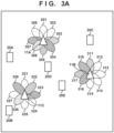
- Beam search processing includes a two-step measurement including a first beam measurement (rough measurement) in which the UEs 20 measure first beams as illustrated in FIG. 3A and a second beam measurement (fine measurement) in which second beams with a smaller beam width that the first beams are measured as illustrated in FIG. 3B .
- the first beams may be referred to as wide beams
- the second beams may be referred to as narrow beams.
- the wide beams may be formed by a combination of a plurality of narrow beams, for example. In one example, the wide beams may be formed by the simultaneous transmission of the same reference signal using a plurality of narrow beams.
- the central processing unit 10 broadcasts an index of wide beams used by the APs 11 to transmit the reference signal and schedule information (first schedule information) relating to indexing timing as the schedule of the first beam measurement.
- the UEs 20 identify the timing of the transmission of the wide beams to be measured by obtaining the broadcast schedule information of the first beam measurement.
- the schedule information includes information designating a resource for the UEs 20 to report the best beam of the wide beams in a time period 402 of FIG. 4 . This allows a collision of feedback reports from the UEs 20 to be avoided.
- the UEs 20 transmit feedback reports to the central processing unit 10 using a control channel via any of the APs 11.
- the reference signal is transmitted from the APs 11 in order using a predetermined number of wide beams with a larger beam width than the narrow beams, the UEs 20 measure the received signal strength of the reference signals transmitted using the wide beams, and the wide beam used in transmitting the reference signal with the highest received signal strength from among the wide beams transmitted from the APs 11 is reported as the best wide beam.
- the reference signal is transmitted via wide beams 301 to 308 of the AP 11A, wide beams 311 to 318 of the AP 11B, and wide beams 321 to 328 of the AP 11C.
- the beam indices 1103 and 1106 are identification information of the wide beam used in the transmission of the reference signal by the APs 11.
- the central processing unit 10 instructs the APs 11 to transmit narrow beams obtained by dividing the wide beams of the indices designated by the feedback reports on the basis of the feedback reports of the best wide beams. Also, in a time period 403 of FIG. 4 , a schedule of the second beam measurement for the UEs 20 is set. Accordingly, the UEs 20 can identify the timing to transmit a second reference signal using narrow beams corresponding to the wide beams of the APs 11 reported to the central processing unit 10 as the best wide beams at the UEs 20. Then, schedule information (second schedule information) designating the parameters transmitted by the reference signal in the second beam measurement is broadcast to the UEs 20. Note that in one example, the central processing unit 10 may unicast the second schedule information.
- the central processing unit 10 restricts the beams of the APs 11 to be measured by the UEs 20 in the second beam measurement, performs scheduling in the time period 403, and reports the information of the beams of the APs 11 to be measured to the UEs in a time period 404.
- the central processing unit 10 determines in the time period 603 to measure the narrow beams from the APs 11 that transmitted a predetermined number of wide beams in order from greatest signal strength, which is a signal strength equal to or greater than a threshold, from among the wide beams with feedback in the time period 402 from the UEs 20.
- the central processing unit 10 determines to measure the narrow beams obtained by dividing three or less wide beams per AP 11. For example, the wide beams 303, 306, 318, and 328 are reported to be best wide beams from the UEs 20, but in the second beam measurement, measurement of the reference signals using the narrow beams corresponding to the wide beams 303, 306, 318, and 328 is not performed. Thus, the length of the second beam measurement period can be reduced while leaving narrow beams that can be used in communication.
- the processing of restricting the beam number to be measured in the second beam measurement by the central processing unit 10 will be described below in detail with reference to FIG. 7 .
- FIG. 7 An example of the processing executed by the central processing unit 10 according to the present embodiment will be described with reference to FIG. 7 .
- the processing illustrated in FIG. 7 is implemented by the processor 101 of the central processing unit 10 executing a program stored in the memory 102.
- the central processing unit 10 broadcasts first scheduling information relating to the schedule of beam transmission in a predetermined time interval and a feedback condition instructing of feedback timing.
- the first scheduling information may include the number of wide beams to be measured and the reference signal transmission interval, and the feedback condition may include information instructing of a threshold for the signal strength of wide beam fed back by the UEs 20.
- the central processing unit 10 transmits the reference signal using the wide beams (first beams) via the APs 11 at the timing reported in advance by the UEs 20.
- the number of sweeps required if N bm1 ⁇ L, where N bm1 is the number of wide beams formable by each AP 11 and L is the number of APs 11.
- the central processing unit 10 receives first feedback information from the UEs 20.
- the first feedback information includes a combination of an index of the best wide beams and the received signal strengths of the reference signals in the index, as described with reference to FIG. 11 .
- the number of combinations of the index of the best wide beams and the received signal strengths of the reference signals in the index included in the first feedback information may be included in the feedback condition.
- the UE 20 may report the received signal strengths of reference signals of equal to or greater than a predetermined received signal strength threshold and a beam index used in the transmission of the reference signals.
- the central processing unit 10 determines whether to transmit the reference signals using the narrow beams from the APs 11 on the basis of the first feedback information received from the UEs 20. For example, as described above, per AP 11, the central processing unit 10 may select a predetermined number of wide beams or less, for example, less than four predetermined UEs 20, in order of highest received signal strength of the first feedback information and transmit the reference signals using the narrow beams corresponding to the selected wide beams. Alternatively, less wide beams than a predetermined number may be selected in order of highest average value of the received signal strength of a plurality of first feedback information from the plurality of APs 11.
- the central processing unit 10 adds together the received signal strengths of the wide beams at the UEs 20 for each index of specific wide beams of the specific APs 11 included in the feedback information received from the UEs 20.
- the summed received signal strength of the wide beams is increased.
- measurement of the narrow beams corresponding to the wide beam in order from the lowest summed received signal strength is determined to not be performed in the second beam measurement.
- the narrow beams corresponding to wide beams with a higher received signal strength can be preferentially measured in the second beam measurement.
- the central processing unit 10 may perform the second measurement for the wide beam of the AP 11 indicating the highest received signal strength from among the best wide beams for each of the UEs 20 from among the received feedback information. Then, for each beam index of the APs 11 other than the beam of the AP 11 indicating the highest received signal strength per UE 20, the received signal strength of the beams may be added together. Also, for each index of the specific beams of the specific APs 11 included in the feedback information, measurement of the narrow beams corresponding to the wide beam in order from the lowest summed received signal strength is determined to not be performed.
- the narrow beams can be measured, and from among the wide beams reported to be the best wide beam from the fewer UEs 20, the wide beams with a lower received signal strength can be preferentially not measured.
- second schedule information including the beam index of the APs 11 to be measured and the parameters that can identify the timing of the transmission of the reference signals using the narrow beams of the APs 11 is reported (S704).
- the UEs 20 identify the timing of transmission of the reference signals on the basis of the received second schedule information.
- the central processing unit 10 transmits the reference signals using the narrow beams using the parameters reported in S704.
- the central processing unit 10 obtains the second feedback information including the measurement result of the reference signals transmitted in S705 from the UEs 20. Accordingly, in S707, the central processing unit 10 can determine the narrow beams to use in the data transmission per UE 20.
- the central processing unit transmits, in the second beam measurement, the narrow beams corresponding to some of the wide beams from among the wide beam request to be transmitted in the second beam measurement from the UEs 20 on the basis of the feedback result of the first beam measurement obtained from the UEs 20. Accordingly, the measurement time of the narrow beams in the second beam measurement can be reduced.
- NPL 1 has been performed into techniques for reducing the number of analog-digital converters (ADC) provided in the AP 11 while ensuring beam gain to the UE 20 using hybrid beamforming combining analog beamforming and digital beamforming in the AP 11.
- ADC analog-digital converters
- hybrid beamforming the number of the RF chains is less than the number of beams formable by the antennas. This can suppress the wireless circuit size of the AP 11 while maintaining beam gain and can reduce the power consumption. Accordingly, the cost of the AP 11 can be reduced.
- the maximum number of the UEs 20 that can simultaneously transmit and receive via the plurality of APs 11 corresponds to the total number of the RF chains provided in the plurality of APs 11. This is because, in a CF MIMO system, data is transmitted simultaneously to one or more UEs 20 via data streams allocated to RF chains of the plurality of APs 11 within a linkable predetermined range. On the other hand, since the number of beams formable by the antennas provided in the AP 11 is greater than the number of the RF chains, the amount of time taken for the beam measurement with respect to the number of the UEs 20 that can simultaneously communicate is longer than in a known analog beamforming system.
- the central processing unit 10 restricts the narrow beams to be measured by the UEs 20 in the second beam measurement from among the narrow beams corresponding to the wide beams reported in the first beam measurement from the UEs 20. This reduces the amount of time needed for the second beam measurement. Note that configurations, functions, and processing that are similar to that of the first embodiment are given the same reference sign and description thereof will be omitted.
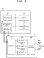
- FIG. 8 illustrates the configuration of the central processing unit 10 and the AP 11 according to the present embodiment.
- the central processing unit 10 includes a digital precoder 801 in the AP control unit 103.
- a predetermined data stream can be allocated to a wireless channel using a superimposed wireless signal transmit from the plurality of APs 11 by the UEs 20.
- the AP 11 includes a predetermined number N RF of RF chains 810i to 810 NRF (hereinafter, also referred to without distinction as RF chain 810) and is connected to a predetermined number N t of antennas 830i to 830 Nt (hereinafter, also referred to without distinction as antenna 830) via an analog precoder 820.
- N t » N RF the number of the RF chains 810 corresponds to the number of data streams. In other words, the number of the UEs 20 that can simultaneously communicate is restricted by the number of the RF chains 810.
- the central processing unit 10 divides the search for analog beams between the APs 11 and the UEs 20 into two stages. For example, in the first measurement, a plurality of analog beams (narrow beams) collectively as a wide beam simultaneously transmit reference signal, and only the best wide beams included in feedback from the UEs 20 transmit the reference signal in order of the plurality of analog beams included in the wide beam. Thus, the best analog beam between the APs 11 and the UEs 20 can be identified.
- the reference signals may not be simultaneously transmitted using the plurality of narrow beams, and the analog precoder 820 may switch between the wide beams and the narrow beams.
- the wide beams may be formed by adding together the narrow beams, and the different beams due to beam width control may be allocated to wide beam and narrow beam.
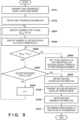
- FIG. 9 illustrates an example of the processing executed by the central processing unit 10 according to the present embodiment.
- the processing illustrated in FIG. 9 is implemented by the processor 101 of the central processing unit 10 executing a program stored in the memory 102.
- the central processing unit 10 broadcasts first scheduling information relating to the schedule of beam transmission in a predetermined time interval and a feedback condition instructing of feedback timing.
- the first scheduling information may include the number of wide beams to be measured and the reference signal transmission interval, and the feedback condition may include information instructing of a threshold for the signal strength of wide beam fed back by the UEs 20.
- S701 and S702 The processing of S701 and S702 is similar to that in the first embodiment and thus will not be described. Note that for narrow beams corresponding to the wide beams of the APs 11 included in the feedback information obtained in S702, at the point in time of S702, all are set to be measured in the second beam measurement. For example, the beam index and the identification information of the UEs 20 to perform measurement are associated together and stored.
- the central processing unit 10 obtains information indicating the number of the RF chains included in AP 11i (AP i ).
- AP i may report the number of the RF chains provided in the AP i to the central processing unit 10 when connecting to the central processing unit 10.
- the central processing unit 10 identifies the number of the UEs 20 that report the wide beams formed by the AP i to be the best wide beams and the received signal strength of the reported beams on the basis of the feedback information received from the UEs 20. Accordingly, the number of the UEs 20 for transmitting and receiving wireless signals can be identified per AP 11.
Landscapes
- Engineering & Computer Science (AREA)
- Computer Networks & Wireless Communication (AREA)
- Signal Processing (AREA)
- Physics & Mathematics (AREA)
- Mathematical Physics (AREA)
- Mobile Radio Communication Systems (AREA)
Abstract
Description
- The present invention relates to a control apparatus, user equipment, a control method, and a program.
- Research into techniques for implementing a user-centric network has looked in a cell-free (CF) multiple-input multiple-output (MIMO) technique that is connected to a central control station using an optical fronthaul and communicates with a piece of user equipment (UE) via a plurality of access points (AP) disposed in an area (NPL 1).
- With a CF MIMO technique, it is assumed that a plurality of APs are disposed in the area. Thus, compared to a known cellular network, the number of APs with a possibility of sending a wireless signal to a predetermined UE may be increased. Also, with a CF MIMO technique, wireless signals are exchanged between the UE and different APs per data stream and it may connect to a central control station. Thus, the number of APs performing channel estimation between a predetermined UE may be increased compared to known MIMO techniques.
-
- NPL1: Wang, Zihuan, et al. "Hybrid Beamforming Design for C-RAN Based mmWave Cell-Free Systems." 2020 IEEE 92nd Vehicular Technology Conference (VTC2020-Fall), IEEE, 2020.
- NPL2: Kojima, Chikara, et al. "Novel two-step beam search method for multi user millimeter-wave communication" 2017 IEEE 28th Annual International Symposium on Personal, Indoor, and Mobile Radio Communications (PIMRC). IEEE, 2017.
- It is necessary to execute beam search processing (NPL2) to search for beams between the APs and the UE to use in communication between the APs and the UE and to perform channel estimation using the found beam. However, as the number of APs that may exchange wireless signals with the UE is increased, a longer amount of time is needed for the beam search processing to identify the APs for the central control station to use in communication with the UE.
- In light of the foregoing, the present invention enables realization of a technique that can reduce the amount of time taken for beam search processing in a cell-free MIMO technique.
- To solve the problem described above, a control apparatus that controls beam search processing between a dispersed plurality of communication apparatus and a plurality of user equipment comprises:
- first instructing means for instructing a communication apparatus to transmit a plurality of first reference signals using different parameters using a plurality of first beams formable by the apparatus;
- first obtaining means for obtaining, from each of the plurality of user equipment, first feedback information including a combination of identification information of one or more first beams and received signal strength in order of highest received signal strength of the first reference signals for each of the plurality of user equipment from among the plurality of first beams used in transmission of the first reference signals by the communication apparatus;
- first determining means for, in a case where a predetermined number or greater of identification information of different first beams is included in a plurality of the first feedback information obtained from the plurality of user equipment by the first obtaining means, determining first beams of a number fewer than the predetermined number to use in measuring second reference signals from among first beams of the predetermined number or greater; and
- first reporting means for reporting, to the plurality of user equipment, a parameter of the second reference signals transmitted using a plurality of second beams that correspond to the first beam of a number fewer than the predetermined number determined to use in measuring by the first determining means and that have a narrower beam width than the first beams.
- According to the present invention, a technique can be provided that can reduce the amount of time taken for beam search processing in a cell-free MIMO technique.
- Other features and advantages of the present invention will be apparent from the following description taken in conjunction with the accompanying drawings. Note that the same reference numerals denote the same or like components throughout the accompanying drawings.
- The accompanying drawings, which are incorporated in and constitute a part of the specification, illustrate embodiments of the invention and, together with the description, serve to explain principles of the invention.
-
FIG. 1 is a diagram illustrating a wireless communication system according to a present embodiment. -
FIG. 2A is a diagram illustrating the configuration of a central processing unit and an access point. -
FIG. 2B is a diagram illustrating the configuration of a user equipment. -
FIG. 3A is a diagram illustrating known one-stage beam selection. -
FIG. 3B is a diagram illustrating known two-stage beam selection. -
FIG. 4 is a diagram illustrating an example of the schedule of known beam search processing. -
FIG. 5A is a diagram illustrating one-stage beam selection according to the present embodiment. -
FIG. 5B is a diagram illustrating two-stage beam selection according to the present embodiment. -
FIG. 6 is a diagram illustrating an example of the schedule of beam search processing according to the present embodiment. -
FIG. 7 is a diagram illustrating an example of processing executed by the central processing unit according to the present embodiment. -
FIG. 8 is a diagram illustrating the configuration of a central processing unit and an access point according to a second embodiment. -
FIG. 9 is a diagram illustrating an example of processing executed by the central processing unit according to the second embodiment. -
FIG. 10A is a diagram illustrating an example of processing executed by a central processing unit according to a third embodiment. -
FIG. 10B is a diagram illustrating an example of processing executed by the central processing unit according to the third embodiment. -
FIG. 11 is a diagram illustrating a message structure of a feedback report according to the present embodiment. - Hereinafter, embodiments will be described in detail with reference to the attached drawings. Note, the following embodiments are not intended to limit the scope of the claimed invention, and limitation is not made to an invention that requires a combination of all features described in the embodiments. Two or more of the multiple features described in the embodiments may be combined as appropriate. Furthermore, the same reference numerals are given to the same or similar configurations, and redundant description thereof is omitted.
-
FIG. 1 illustrates an example of the configuration of a wireless communication system according to the present embodiment. Awireless communication system 1 is a 5G cellular communication system (mobile communication network), for example. However, no such limitation is intended, and the system of the present embodiment may be a cellular communication system of a 5G successor or a non-cellular wireless communication system. The present system may include acentral processing unit 10, access points (APs) 11A to 11C (also referred to below without distinction as AP 11), and user equipment (UE) 20A to 20E (also referred to below without distinguish as UE 20). Note that inFIG. 1 , threeAPs 11 and fiveUEs 20 are illustrated, but the number of apparatuses are not limited thereto. - The
wireless communication system 1 according to the present embodiment performs MIMO communication between thecentral processing unit 10 and the UEs 20 via theAPs 11 that are dispersed in the service area in which thecentral processing unit 10 provides a service and that are controlled by thecentral processing unit 10. By thecentral processing unit 10 making theAPs 11 cooperate in operations, as in a known wireless communication system, a decrease in communication quality due to the positional relationship between thecentral processing unit 10 and the UEs 20 can be prevented, and the UEs 20 can receive a communication service of at least a constant quality anywhere in the service area. Such cell-free (CF) MIMO techniques are currently being researched. - The
central processing unit 10 according to the present embodiment is a control apparatus that performs overall control of theAPs 11. Note that in the present embodiment described herein, millimeter waves are used in the wireless communication between theAPs 11 and theUEs 20. Thecentral processing unit 10 communicates with theUEs 20 via theAPs 11 connected via an optical fronthaul. Also, by connecting to a core network, theUEs 20 can be provided with internet access. - The
APs 11 are exchange points that are connected to thecentral processing unit 10 via the optical fronthaul and that exchange wireless signals according to instructions from a base station. TheAPs 11 each include a plurality of antennas and can perform beamforming according to control by thecentral processing unit 10. - The configuration of the
central processing unit 10 and theAP 11 will now be described with reference toFIG. 2A . - The
central processing unit 10 includes aprocessor 101, amemory 102, anAP control unit 103, and a core network (CN)communication unit 104 communicatively connected to one another via abus 105. - The
processor 101 is a control unit that executes a program stored in thememory 102 and controls the entire operations of thecentral processing unit 10. Theprocessor 101 may be one or more processors including a central processing unit (CPU), an application specific integrated circuit (ASIC), a field-programmable gate array (FPGA), a digital signal processor (DSP), and the like. Thememory 102 is a storage unit that stores programs executed by theprocessor 101 and various types of data used by theprocessor 101 to control thecentral processing unit 10. For example, thecentral processing unit 10 includes a computer including theprocessor 101 and thememory 102. - The
AP control unit 103 is an interface (IF) for performing control of theAPs 11. TheAP control unit 103 transmits data streams to be transmitted to theUEs 20 to theAPs 11 and receives data streams from theUEs 20 via theAPs 11. In the present embodiment, theAP control unit 103 is an IF that communicates with theAPs 11 via an optical fronthaul. - The
CN communication unit 104, which thecentral processing unit 10 uses for communication, is a wired or wireless communication unit that communicates with the core network. - The
AP 11 is a remote radio head (RRH) that outputs a signal transmitted from thecentral processing unit 10. TheAP 11, together with a signal received from theAP control unit 103, transmits a signal received from theUE 20 to theAP control unit 103 via a control IF 111. Also, the transmitting and receiving of signals by theAPs 11 is controlled by thecentral processing unit 10 via the control interface (IF) 111. The data instructing for transmission from thecentral processing unit 10 is transmitted via wireless signal via at least one of the plurality ofantennas 113 via awireless communication circuit 112 to form a beam. Thecentral processing unit 10 can instruct aspecific UE 20 to perform data transmission using a plurality of beams formable by theAPs 11 to perform CF MIMO transmission. Also, thecentral processing unit 10 can simultaneously transmit wireless signals to one of theUEs 20 from the plurality ofAPs 11, to the plurality ofUEs 20 from oneAP 11, and to the plurality ofUEs 20 from the plurality ofAPs 11. - The configuration of the user equipment (UE) 20 will now be described with reference to
FIG. 2B . TheUE 20 includes aprocessor 201, amemory 202, and awireless communication circuit 203 communicatively connected to one another via abus 204. - The
processor 201 is a control unit that executes a program stored in thememory 202 and controls the entire operations of theUE 20. Theprocessor 201 may be one or more processors including a central processing unit (CPU), an application specific integrated circuit (ASIC), a field-programmable gate array (FPGA), a digital signal processor (DSP), and the like. Thememory 202 is a storage unit that stores programs executed by theprocessor 201 and various types of data used by theprocessor 201 toUE 20. - The
wireless communication circuit 203 is a wireless circuit for exchanging wireless signals with theAPs 11 and is connected to one or more antennas. TheUE 20 according to the present embodiment executes beam search processing to measure beams used in MIMO communication with theAPs 11, as described below. A plurality of beams with a low correlation and good signal quality are detected via beam search processing, and by transmitting and receiving data on streams allocated to the plurality of beams, the throughput between theUEs 20 and thecentral processing unit 10 can be improved. Note that in the present embodiment described herein, the antenna directionality of theUEs 20 is non-directional. However,UEs 20 with different directionality may be used. - Next, known beam search processing will be described with reference to
FIGS. 3A ,3B , and4 . - An overview of beams measured via beam search will now be described with reference of
FIGS. 3A and3B . Beam search processing includes a two-step measurement including a first beam measurement (rough measurement) in which theUEs 20 measure first beams as illustrated inFIG. 3A and a second beam measurement (fine measurement) in which second beams with a smaller beam width that the first beams are measured as illustrated inFIG. 3B . The first beams may be referred to as wide beams, and the second beams may be referred to as narrow beams. The wide beams may be formed by a combination of a plurality of narrow beams, for example. In one example, the wide beams may be formed by the simultaneous transmission of the same reference signal using a plurality of narrow beams. - Note that the
central processing unit 10 broadcasts an index of wide beams used by theAPs 11 to transmit the reference signal and schedule information (first schedule information) relating to indexing timing as the schedule of the first beam measurement. TheUEs 20 identify the timing of the transmission of the wide beams to be measured by obtaining the broadcast schedule information of the first beam measurement. Also, the schedule information includes information designating a resource for theUEs 20 to report the best beam of the wide beams in atime period 402 ofFIG. 4 . This allows a collision of feedback reports from theUEs 20 to be avoided. Note that theUEs 20 transmit feedback reports to thecentral processing unit 10 using a control channel via any of theAPs 11. - In the first beam measurement of a
time period 401 ofFIG. 4 , the reference signal is transmitted from theAPs 11 in order using a predetermined number of wide beams with a larger beam width than the narrow beams, theUEs 20 measure the received signal strength of the reference signals transmitted using the wide beams, and the wide beam used in transmitting the reference signal with the highest received signal strength from among the wide beams transmitted from theAPs 11 is reported as the best wide beam. For example, in thetime period 401 ofFIG. 4 , as illustrated inFIG. 3A , the reference signal is transmitted viawide beams 301 to 308 of theAP 11A,wide beams 311 to 318 of theAP 11B, andwide beams 321 to 328 of theAP 11C. TheUEs 20 measure the received signal strength of the reference signal transmitted using the wide beams formable by theAPs 11 and determine the beam measured to have a reference signal with the highest received signal strength to be the best wide beam. In one example, theUEs 20 may determine the beam measured to have a reference signal with the highest signal-to-noise ratio (SN ratio) as the best wide beam. - In this example, the
UE 20A determines thewide beams UE 20B determines thewide beams UE 20C determines thewide beams UE 20D determines thewide beams UE 20E determines thewide beams - Next, in the
time period 402 ofFIG. 4 , feedback of the best wide beams determined in thetime period 401 is performed by theUEs 20. As illustrated inFIG. 11 , the feedback information (feedback report) includes, as parameters,identification information 1101 of theUEs 20,identification information 1102 of thefirst APs 11, abeam index 1103 used in transmission of the reference signal with the highest received signal strength from among the reference signals from thefirst APs 11, and a highest receivedsignal strength 1104 from among the reference signals received from thefirst APs 11. Also, forother APs 11, a combination of identification information, a beam index of the best wide beams, and received signal strength may be included as indicated by 1105 to 1107. Note that in the present embodiment described herein, only the highest received signal strength per AP is reported. However, a combination of a beam index and received signal strength of two or more received signal strengths may be reported in order per AP. Thebeam indices APs 11. - The
central processing unit 10 instructs theAPs 11 to transmit narrow beams obtained by dividing the wide beams of the indices designated by the feedback reports on the basis of the feedback reports of the best wide beams. Also, in atime period 403 ofFIG. 4 , a schedule of the second beam measurement for theUEs 20 is set. Accordingly, theUEs 20 can identify the timing to transmit a second reference signal using narrow beams corresponding to the wide beams of theAPs 11 reported to thecentral processing unit 10 as the best wide beams at theUEs 20. Then, schedule information (second schedule information) designating the parameters transmitted by the reference signal in the second beam measurement is broadcast to theUEs 20. Note that in one example, thecentral processing unit 10 may unicast the second schedule information. - Thus, in a
time period 405 ofFIG. 4 , as illustrated inFIG. 3B , the second reference signal is transmitted by theAP 11A vianarrow beams 3031 to 3033 corresponding to thewide beam 303, narrow beams 3041 to 3043 corresponding to thewide beam 304,narrow beams 3051 to 3053 corresponding to thewide beam 305,narrow beams 3061 to 3063 corresponding to thewide beam 306, andnarrow beams 3071 to 3073 corresponding to thewide beam 307. In a similar manner, the second reference signal is transmitted by theAP 11B vianarrow beams 3111 to 3113 corresponding to thewide beam 311,narrow beams 3161 to 3163 corresponding to thewide beam 316,narrow beams 3171 to 3173 corresponding to thewide beam 317, andnarrow beams 3181 to 3183 corresponding to thewide beam 318. In a similar manner, the reference signal is transmitted by theAP 11C vianarrow beams 3221 to 3223 corresponding to thewide beam 322,narrow beams 3231 to 3233 corresponding to thewide beam 323, narrow beams 3261 to 3263 corresponding to thewide beam 326, andnarrow beams 3281 to 3283 corresponding to thewide beam 328. In a similar manner to the wide beams, theUEs 20 measure the received signal strength of the second reference signal transmitted from theAPs 11 and determine the narrow beam used in the transmission of the reference signal with the highest received signal strength to be the best narrow beam. In one example, theUEs 20 may determine the beam measured to have a reference signal with the highest signal-to-noise ratio (SN ratio) as the best narrow beam. - In this example, the
UE 20A determines thenarrow beams UE 20B determines thenarrow beams 3061 and 3262 to be the best narrow beams. Also, theUE 20C determines thenarrow beams 3032 and 3112 to be the best narrow beams, theUE 20D determines thenarrow beams UE 20E determines thenarrow beams - Next, in a
time period 406 ofFIG. 4 , feedback of the best narrow beams determined in thetime period 405 is performed by theUEs 20. Accordingly, thecentral processing unit 10 learns what beams to use for communication with eachUE 20. Note that feedback information (second feedback information) to be transmitted in thetime period 406 may also use a structure similar to that illustrated inFIG. 11 . In other words, the identification information of the narrow beams used in the transmission of the second reference signal by theAPs 11 and the received signal strength may be transmitted to thecentral processing unit 10 as the second feedback information. - In this example, in CF MIMO, the number of the
UEs 20 that can communicate with theAPs 11 is higher than that in known MIMO communication. Thus, with this increase in the number of theUEs 20, the number of narrow beams needed to be transmitted perAP 11 is also increased. This results in a problematic decrease in the effect of reducing the number of sweeps by two-stage beam selection. Also, there is an issue in CF MIMO that since a large number of theAPs 11 are dispersed in the service area, the number ofAPs 11 is increased. - In CF MIMO using millimeter waves for the purpose of improving throughput, compared to wireless signals of a lower frequency, millimeter wave signals are greatly affected by distance attenuation. Thus, the
APs 11 need to be disposed in a high density in the service area, again leading to the issue of an increase in the number ofAPs 11. - In the
wireless communication system 1 according to the present embodiment, by restricting the beam number of theAPs 11 that theUEs 20 measure, the amount of time taken for beam selection is reduced. - Next, the flow of beam selection according to the present embodiment will be described.
-
FIG. 5A is similar toFIG. 3A and thus will not be described. This also applies to the feedback from theUEs 20 in thetime period 402 ofFIG. 6 . - Next, in 603 of
FIG. 6 , thecentral processing unit 10 restricts the beams of theAPs 11 to be measured by theUEs 20 in the second beam measurement, performs scheduling in thetime period 403, and reports the information of the beams of theAPs 11 to be measured to the UEs in atime period 404. - For example, the
central processing unit 10 determines in thetime period 603 to measure the narrow beams from theAPs 11 that transmitted a predetermined number of wide beams in order from greatest signal strength, which is a signal strength equal to or greater than a threshold, from among the wide beams with feedback in thetime period 402 from theUEs 20. - Thus, in the
time period 603, the number of narrow beams to be measured by eachUE 20 in thetime period 405 can be reduced. For example, in the example illustrated inFIG. 5B , thecentral processing unit 10 determines to measure the narrow beams obtained by dividing three or less wide beams perAP 11. For example, thewide beams UEs 20, but in the second beam measurement, measurement of the reference signals using the narrow beams corresponding to thewide beams central processing unit 10 will be described below in detail with reference toFIG. 7 . - Next, an example of the processing executed by the
central processing unit 10 according to the present embodiment will be described with reference toFIG. 7 . The processing illustrated inFIG. 7 is implemented by theprocessor 101 of thecentral processing unit 10 executing a program stored in thememory 102. - Note that separate from the processing illustrated in
FIG. 7 , thecentral processing unit 10 broadcasts first scheduling information relating to the schedule of beam transmission in a predetermined time interval and a feedback condition instructing of feedback timing. Also, the first scheduling information may include the number of wide beams to be measured and the reference signal transmission interval, and the feedback condition may include information instructing of a threshold for the signal strength of wide beam fed back by theUEs 20. - First, in S701, the
central processing unit 10 transmits the reference signal using the wide beams (first beams) via theAPs 11 at the timing reported in advance by theUEs 20. The number of sweeps required if Nbm1 × L, where Nbm1 is the number of wide beams formable by eachAP 11 and L is the number ofAPs 11. - Next, in S702, the
central processing unit 10 receives first feedback information from theUEs 20. For example, the first feedback information includes a combination of an index of the best wide beams and the received signal strengths of the reference signals in the index, as described with reference toFIG. 11 . The number of combinations of the index of the best wide beams and the received signal strengths of the reference signals in the index included in the first feedback information may be included in the feedback condition. Alternatively, theUE 20 may report the received signal strengths of reference signals of equal to or greater than a predetermined received signal strength threshold and a beam index used in the transmission of the reference signals. - Next, in S703, the
central processing unit 10 determines whether to transmit the reference signals using the narrow beams from theAPs 11 on the basis of the first feedback information received from theUEs 20. For example, as described above, perAP 11, thecentral processing unit 10 may select a predetermined number of wide beams or less, for example, less than fourpredetermined UEs 20, in order of highest received signal strength of the first feedback information and transmit the reference signals using the narrow beams corresponding to the selected wide beams. Alternatively, less wide beams than a predetermined number may be selected in order of highest average value of the received signal strength of a plurality of first feedback information from the plurality ofAPs 11. - Also, for example, the
central processing unit 10 adds together the received signal strengths of the wide beams at theUEs 20 for each index of specific wide beams of thespecific APs 11 included in the feedback information received from theUEs 20. Thus, in a case where feedback includes the same wide beams of thesame APs 11 being the best wide beams from a plurality of theUEs 20, the summed received signal strength of the wide beams is increased. Also, for each index of the specific wide beams of thespecific APs 11 included in the feedback information, measurement of the narrow beams corresponding to the wide beam in order from the lowest summed received signal strength is determined to not be performed in the second beam measurement. Thus, from among the wide beams reported to be the best wide beams from a larger number of theUEs 20, the narrow beams corresponding to wide beams with a higher received signal strength can be preferentially measured in the second beam measurement. - Also, the
central processing unit 10 may perform the second measurement for the wide beam of theAP 11 indicating the highest received signal strength from among the best wide beams for each of theUEs 20 from among the received feedback information. Then, for each beam index of theAPs 11 other than the beam of theAP 11 indicating the highest received signal strength perUE 20, the received signal strength of the beams may be added together. Also, for each index of the specific beams of thespecific APs 11 included in the feedback information, measurement of the narrow beams corresponding to the wide beam in order from the lowest summed received signal strength is determined to not be performed. Thus, for a best wide beam indicating a received signal strength with a high probability of obtaining a high beam gain perUE 20, the narrow beams can be measured, and from among the wide beams reported to be the best wide beam from thefewer UEs 20, the wide beams with a lower received signal strength can be preferentially not measured. - Then, when it is determined to measure the narrow beams corresponding to less than the predetermined number of wide beams in the second beam measurement, in S704, second schedule information including the beam index of the
APs 11 to be measured and the parameters that can identify the timing of the transmission of the reference signals using the narrow beams of theAPs 11 is reported (S704). TheUEs 20 identify the timing of transmission of the reference signals on the basis of the received second schedule information. - Next, in S705, the
central processing unit 10 transmits the reference signals using the narrow beams using the parameters reported in S704. - Next, in S706, the
central processing unit 10 obtains the second feedback information including the measurement result of the reference signals transmitted in S705 from theUEs 20. Accordingly, in S707, thecentral processing unit 10 can determine the narrow beams to use in the data transmission perUE 20. - As described above, the central processing unit according to the present embodiment transmits, in the second beam measurement, the narrow beams corresponding to some of the wide beams from among the wide beam request to be transmitted in the second beam measurement from the
UEs 20 on the basis of the feedback result of the first beam measurement obtained from theUEs 20. Accordingly, the measurement time of the narrow beams in the second beam measurement can be reduced. - Research has been performed (NPL 1) into techniques for reducing the number of analog-digital converters (ADC) provided in the
AP 11 while ensuring beam gain to theUE 20 using hybrid beamforming combining analog beamforming and digital beamforming in theAP 11. With hybrid beamforming, the number of the RF chains is less than the number of beams formable by the antennas. This can suppress the wireless circuit size of theAP 11 while maintaining beam gain and can reduce the power consumption. Accordingly, the cost of theAP 11 can be reduced. - In a case where the
AP 11 performs hybrid beamforming, the maximum number of theUEs 20 that can simultaneously transmit and receive via the plurality ofAPs 11 corresponds to the total number of the RF chains provided in the plurality ofAPs 11. This is because, in a CF MIMO system, data is transmitted simultaneously to one ormore UEs 20 via data streams allocated to RF chains of the plurality ofAPs 11 within a linkable predetermined range. On the other hand, since the number of beams formable by the antennas provided in theAP 11 is greater than the number of the RF chains, the amount of time taken for the beam measurement with respect to the number of theUEs 20 that can simultaneously communicate is longer than in a known analog beamforming system. Thus, on the basis of the number of the RF chains provided in eachAP 11, thecentral processing unit 10 according to the present embodiment restricts the narrow beams to be measured by theUEs 20 in the second beam measurement from among the narrow beams corresponding to the wide beams reported in the first beam measurement from theUEs 20. This reduces the amount of time needed for the second beam measurement. Note that configurations, functions, and processing that are similar to that of the first embodiment are given the same reference sign and description thereof will be omitted. -
FIG. 8 illustrates the configuration of thecentral processing unit 10 and theAP 11 according to the present embodiment. - The
central processing unit 10 includes adigital precoder 801 in theAP control unit 103. Thus, a predetermined data stream can be allocated to a wireless channel using a superimposed wireless signal transmit from the plurality ofAPs 11 by theUEs 20. - Also, the
AP 11 includes a predetermined number NRF of RF chains 810i to 810NRF (hereinafter, also referred to without distinction as RF chain 810) and is connected to a predetermined number Nt of antennas 830i to 830Nt (hereinafter, also referred to without distinction as antenna 830) via ananalog precoder 820. Note that Nt » NRF. In the present embodiment, the number of the RF chains 810 corresponds to the number of data streams. In other words, the number of theUEs 20 that can simultaneously communicate is restricted by the number of the RF chains 810. - In this example, to search for an analog beam, the best beams between all of the
APs 11 and theUEs 20 and the received power value is required. Thus, a large amount of time is required for beam sweeping. Thus, thecentral processing unit 10 according to the present embodiment divides the search for analog beams between theAPs 11 and theUEs 20 into two stages. For example, in the first measurement, a plurality of analog beams (narrow beams) collectively as a wide beam simultaneously transmit reference signal, and only the best wide beams included in feedback from theUEs 20 transmit the reference signal in order of the plurality of analog beams included in the wide beam. Thus, the best analog beam between theAPs 11 and theUEs 20 can be identified. Note that in a case where the corresponding relationship between the wide beams and the narrow beams is set in advance, the reference signals may not be simultaneously transmitted using the plurality of narrow beams, and theanalog precoder 820 may switch between the wide beams and the narrow beams. In other words, the wide beams may be formed by adding together the narrow beams, and the different beams due to beam width control may be allocated to wide beam and narrow beam. -
FIG. 9 illustrates an example of the processing executed by thecentral processing unit 10 according to the present embodiment. The processing illustrated inFIG. 9 is implemented by theprocessor 101 of thecentral processing unit 10 executing a program stored in thememory 102. - Note that as in the first embodiment, the
central processing unit 10 broadcasts first scheduling information relating to the schedule of beam transmission in a predetermined time interval and a feedback condition instructing of feedback timing. Also, the first scheduling information may include the number of wide beams to be measured and the reference signal transmission interval, and the feedback condition may include information instructing of a threshold for the signal strength of wide beam fed back by theUEs 20. - The processing of S701 and S702 is similar to that in the first embodiment and thus will not be described. Note that for narrow beams corresponding to the wide beams of the
APs 11 included in the feedback information obtained in S702, at the point in time of S702, all are set to be measured in the second beam measurement. For example, the beam index and the identification information of theUEs 20 to perform measurement are associated together and stored. - Next, in S903, the
central processing unit 10 obtains information indicating the number of the RF chains included in AP 11i (APi). For example, APi may report the number of the RF chains provided in the APi to thecentral processing unit 10 when connecting to thecentral processing unit 10. - Next, in S904, the
central processing unit 10 identifies the number of theUEs 20 that report the wide beams formed by the APi to be the best wide beams and the received signal strength of the reported beams on the basis of the feedback information received from theUEs 20. Accordingly, the number of theUEs 20 for transmitting and receiving wireless signals can be identified perAP 11. - Next, in S905, it is determined whether or not the number (NUE) of
UEs 20 with feedback that the wide beams used in the transmission of the reference signal by the APi are the best wide beams is less than the number (NRFAP) of the RF chains of theAP 11. In a case where the number NUE of theUEs 20 with feedback of the received strength of the beams transmitted by theAP 11 is less than the number NRFAP of the RF chains (YES in S905), theAP 11 can form an analog beam for theUEs 20. Thus, thecentral processing unit 10 determines not to reduce the number of beams to be measured in the second beam measurement for theAP 11. Then, the processing proceeds to S907, and it is determined whether or not the determination of whether or not the number of theUEs 20 to perform beam measurement is less than the number of the RF chains of theAP 11 is complete for all of theAPs 11. In a case where there is still an AP for which the processing of S905 to S906 has not been executed (NO in S907), the processing of S903 to S906 is executed for thenext AP 11. In a case where the number of theUEs 20 to perform beam measurement is less than the number of the RF chains of theAP 11 for all of the APs 11 (YES in S907), the processing of S909 onward is executed. - On the other hand, in a case where the number of the
UEs 20 with feedback of the received strength of the wide beams transmitted by theAPs 11 is equal to or greater than the number of RF chains (NO in S905), thecentral processing unit 10 advances the processing to S906, and it is determined to not allocate RF chains to theUEs 20 that reported low received signal strength from among the feedback information from theUEs 20 for theAP 11. In other words, an improvement in throughput can be expect by allocating RF chains toother UEs 20 as opposed to theUEs 20 that reported the lowest received signal strength. Thus, the second beam measurement instruction is not issued for theAP 11. Accordingly, even when the second beam measurement is performed, it can be made that theUEs 20 with a relatively low possibility of finding a narrow beam from which a high beam gain can be obtained do not perform the second beam measurement. - Note that in S906, from the feedback information from the
UEs 20 for thepredetermined AP 11, per beam index of the wide beams of theAP 11, the received signal strength of theUEs 20 are added together, and it may be determined to not measure the reference signals using the narrow beams corresponding to the wide beams in order of lowest summed received signal strength. Thus, from among the wide beams reported to be the best beams from a larger number of theUEs 20, the wide beams with higher received signal strength can be preferentially measured. Also, from among theUEs 20 that transmitted feedback information for the wide beams determined to perform second beam measurement for, it may be determined to not allocate RF chains to theUEs 20 that reported a low received signal strength. Accordingly, the number of the narrow beams measured in the second beam measurement can be reduced, and theUEs 20 allocated to the RF chain can be restricted. In a case where it is determined to not allocate to the RF chains, in the second beam measurement, by not measuring the reference signals of the narrow beams corresponding to the wide beams not allocated to theUEs 20, the amount of time needed for a feedback report can be reduced, and the power consumption of theUEs 20 can be reduced. - When the processing of S906 ends, the
central processing unit 10 returns the processing to S905 and determines whether or not the number of theUEs 20 with feedback of the wide beams transmitted by theAP 11 is less than the number of RF chains of theAP 11. - By repeating the processing of S904 to S906 for all of the
APs 11, TheUEs 20 with more than the number ofUEs 20 that can be allocated with a data stream from theAP 11 can be made to not measure the reference signals of the narrow beams for theAP 11. Thus, the RF chains can be allocated to theUEs 20 at the beam measurement stage on the basis of the second beam measurement with a greater number compared to the RF chains. - When a number of the
UEs 20 less than the number of possible RF chain allocations are allocated for all of theAPs 11, thecentral processing unit 10 reports the second schedule information that can identify the beam index of theAPs 11 to be measured in the second beam measurement and the timing to transmit the reference signals using the narrow beams of theAP 11 to each UE 20 (S909). The processing of S705 to S707 after S909 is similar to that in the first embodiment and thus will not be described. - As described above, the central processing unit according to the present embodiment transmits, in the second beam measurement, the narrow beams corresponding to some of the wide beams from among the wide beam request to be transmitted in the second beam measurement from the
UEs 20 on the basis of the feedback result of the first beam measurement obtained from theUEs 20. In this example, the wide beams corresponding to the narrow beams to be measured in the second beam measurement are restricted on the basis of the number of the RF chains provided in theAP 11. Accordingly, the measurement time of the narrow beams in the second beam measurement can be reduced, and the possibility of theUE 20 with a low possibility of being targeted with an analog beam from theAP 11 upon data transmission performing the measurement of a beam formed by theAP 11 can be reduced. - Also, as described above, the
central processing unit 10 according to the present embodiment in the beam measurement allocates RF chains to theUEs 20 with feedback of a high received signal strength. Thus, in the subsequent data transmission, the throughput of thewireless communication system 1 can be improved. - In the third embodiment, an example of processing will be described in which the central processing unit restricts the beams to be measured on the basis of the number of data streams that the UE can simultaneously transmit and receive data on. Note that configurations, functions, and processing that are similar to that of the first and second embodiment are given the same reference sign and description thereof will be omitted.
-
FIGS. 10A and10B are diagrams illustrating an example of processing executed by thecentral processing unit 10 according to the present embodiment. - S701 and S702 are similar to that in the first embodiment and thus will not be described. Note that when transmitting feedback of the first beam measurement, the
UE 20 according to the present embodiment reports to thecentral processing unit 10 the number of the RF chains as the number of data streams that theUE 20 can simultaneously transmit and receive data on. For example, theUE 20 determines the number of the best wide beams of theAPs 11 included in the feedback report according to the number of the RF chains. For example, theUE 20 reports a number of the best wide beams of theAPs 11 which is twice the number of the RF chains provided in theUE 20. Accordingly, in S1003, thecentral processing unit 10 can identify the number of the RF chains provided in theUE 20 on the basis of the number of the best wide beams of theAPs 11 included in the feedback report. Alternatively, theUE 20 may report the number of the RF chains provided in theUE 20 to thecentral processing unit 10 via the control channel. - Next, in S1004, the
central processing unit 10 determines the wide beam deletion candidates on the basis of the first feedback information received from theUEs 20. In S1004, as in the first embodiment, the received signal strengths received from theUEs 20 per beam index are added together, and the deletion candidate may be determined in order of the lowest summed received signal strength. When a wide beam is deleted, thecentral processing unit 10 does not transmit the second reference signal using the narrow beams corresponding to the deleted wide beam. - Next, the
central processing unit 10 advances the processing to S1005 and identifies the UE 20 (UEk) with the feedback of the best wide beam being the deletion candidate wide beam. Then, in a case where the deletion candidate wide beam has been deleted, thecentral processing unit 10 determines whether or not the number of theAPs 11 measured by the UEk identified in S105 is less than the number of the RF chains of the UEk (S1006). In a case where the number of theAPs 11 measured by the UEk is less than the number of the RF chains of the UEk (YES in S1006), measurement of the narrow beams corresponding to the wide beam is omitted, leading to a possibility that the throughput in the subsequent data transmission by the UEk may not be improved. Thus, it is determined to not delete the beam (S1007), and the processing proceeds to S1009. - In a case where the number of the
APs 11 measured by the UEk is not less than the number of the RF chains of the UEk (NO in S1006), even when the measurement of the narrow beams corresponding to the deletion candidate wide beam is omitted, the throughput in the subsequent data transmission by the UEk via the beams between theother APs 11 can be improved. Thus, it is determined to delete the beam (S1007), and the processing proceeds to S1009. - In S1009, the
central processing unit 10 determines whether or not determination for whether or not to delete has been performed for all of the deletion candidate wide beams. In a case where determination for all of the deletion candidate wide beams has not ended (NO in S1009), thecentral processing unit 10 returns the processing to S1005 and repeats the processing of S1005 to S1008. - In a case where the
central processing unit 10 determines that whether or not to delete has been performed for all of the deletion candidate wide beams has been determined (YES in S1009), thecentral processing unit 10 advances the processing to S909. The subsequent processing is similar to that inFIG. 9 and thus will not be described. - In this manner, by determining to not measure in the second beam measurement, a reduction to the throughput of the
specific UE 20 can be prevented, and the amount of time needed for the second beam measurement can be reduced. - The invention is not limited to the foregoing embodiments, and various variations/changes are possible within the spirit of the invention.
- The user equipment according to the present embodiment described above reports wide beams that received reference signals with the highest received signal strength per access point. However, in one example, the user equipment may feed back a plurality of received signal strengths of reference signals received at different timing from a plurality of wide beams of one access point to the central processing unit. Also, on the basis of the fed back plurality of wide beams, the identification information of a plurality of narrow beams may be transmitted to the
central processing unit 10 in order of the highest received signal strength of the reference signal transmitted using the narrow beams corresponding to the plurality of wide beams. In this manner, feedback information relating to a plurality of narrow beams for transmitting and receiving data using a plurality of narrow beams from one access point can be provided to thecentral processing unit 10. Also, the user equipment may transmit the difference in signal strength from the strongest wide beam for each of the plurality of wide beams. - The present application claims priority from
Japanese Patent Application No. 2022-030078 filed on February 28, 2022
Claims (14)
- A control apparatus that controls beam search processing between a dispersed plurality of communication apparatus and a plurality of user equipment, the control apparatus comprising:first instructing means for instructing a communication apparatus to transmit a plurality of first reference signals using different parameters using a plurality of first beams formable by the apparatus;first obtaining means for obtaining, from each of the plurality of user equipment, first feedback information including a combination of identification information of one or more first beams and received signal strength in order of highest received signal strength of the first reference signals for each of the plurality of user equipment from among the plurality of first beams used in transmission of the first reference signals by the communication apparatus;first determining means for, in a case where a predetermined number or greater of identification information of different first beams is included in a plurality of the first feedback information obtained from the plurality of user equipment by the first obtaining means, determining first beams of a number fewer than the predetermined number to use in measuring second reference signals from among first beams of the predetermined number or greater; andfirst reporting means for reporting, to the plurality of user equipment, a parameter of the second reference signals transmitted using a plurality of second beams that correspond to the first beam of a number fewer than the predetermined number determined to use in measuring by the first determining means and that have a narrower beam width than the first beams.
- The control apparatus according to claim 1, wherein
the first determining means, per the identification information, selects the first beam of a number less than the predetermined number in order of a highest number included in the plurality of first feedback information obtained from the plurality of user equipment and determines to measure the second reference signals using second beams corresponding to the first beams of a number less than the predetermined number. - The control apparatus according to claim 1 or 2, wherein
the first determining means, per the identification information, adds together received signal strengths of the first reference signals included in the plurality of first feedback information obtained from the plurality of user equipment, selects the first beam of a number less than the predetermined number in order of the highest summed received signal strength, and determines to measure the second reference signals using second beams corresponding to the first beams of a number less than the predetermined number. - The control apparatus according to any one of claims 1 to 3, further comprisingfirst identifying means for identifying a data stream number that the communication apparatus can simultaneously transmit and receive data on,wherein the first determining means determines for measurement of the second reference signals to be performed using the second beams corresponding to the first beams of a number less than the data stream number identified by the first identifying means.
- The control apparatus according to any one of claims 1 to 4, further comprisingsecond identifying means for obtaining a data stream number that each of the plurality of user equipment can simultaneously transmit and receive data on,wherein the first determining means selects a first beam of the communication apparatus so that each of the plurality of user equipment measures a reference signal transmitted from a number of the plurality of communication apparatus equal to or greater than the data stream number identified by the second identifying means and determines for measurement of the second reference signals to be performed using the second beams corresponding to the first beams of a number less than the predetermined number.
- The control apparatus according to any one of claims 1 to 5, further comprising
second reporting means for reporting a parameter of the first reference signals transmitted using the plurality of first beams to the plurality of user equipment. - The control apparatus according to any one of claims 1 to 6, wherein
the first reporting means associates together and reports, as the parameter of the second reference signals, identification information of a predetermined second beam and identification information of a user equipment instructing to measure the second reference signals transmitted using the predetermined second beam. - The control apparatus according to any one of claims 1 to 7, wherein
the first reporting means reports a timing for transmitting the second reference signals as the parameter of the second reference signals. - The control apparatus according to any one of claims 1 to 8, further comprising
second obtaining means for obtaining second feedback information including a combination of identification information of one or more second beams in order of highest received signal strength of the second reference signals for each of the plurality of user equipment from among the plurality of second beams used in transmission of the second reference signals by the communication apparatus and the received signal strengths. - The control apparatus according to claim 9, further comprising:
second determining means for determining a second beam to use in transmission between at least one of the plurality of user equipment and the communication apparatus on a basis of the second feedback information obtained by the second obtaining means. - The control apparatus according to any one of claims 1 to 10, wherein
the first obtaining means obtains first feedback information including a combination of a different in received strength with a received signal strength of a first reference signal with a highest received signal strength for a predetermined user equipment from among the plurality of first reference signals transmitted by the communication apparatus and identification information of a first beam used in transmission of the first reference signal. - A user equipment that measures a beam transmitted from a dispersed plurality of communication apparatuses controlled by a control apparatus, the user equipment comprising:first measuring means for measuring received signal strength of a plurality of first reference signal transmitted using a plurality of first beams formable by a predetermined communication apparatus from among the plurality of communication apparatuses;transmitting means for transmitting, to the control apparatus, first feedback information including a combination of identification information of a first beam used in transmission of one or more of the first reference signals in order from highest received signal strength for the user equipment from among the plurality of first reference signals measured by the first measuring means and received signal strength;receiving means for receiving, from the control apparatus, a parameter of second reference signals transmitted using a plurality of second beams that correspond to a first beam and that have a narrower beam width than the first beam; andsecond measuring means for measuring received signal strength of the second reference signals transmitted using the second beams by the communication apparatus in a case where the parameter of the second reference signals received by the receiving means includes a parameter of a second reference signal transmitted using a second beam corresponding to the first beam included in the first feedback information.
- A control method executed by a control apparatus that controls beam search processing between a dispersed plurality of communication apparatus and a plurality of user equipment, the control method comprising:instructing a communication apparatus to transmit a plurality of first reference signals using different parameters using a plurality of first beams formable by the communication apparatus;obtaining, from each of the plurality of user equipment, first feedback information including a combination of identification information of one or more first beams and received signal strength in order of highest received signal strength of the first reference signals for each of the plurality of user equipment from among the plurality of first beams used in transmission of the first reference signals by the communication apparatus;in a case where a predetermined number or greater of identification information of different first beams is included in a plurality of the first feedback information obtained from the plurality of user equipment, determining first beams of a number fewer than the predetermined number to use in measuring second reference signals from among first beams of the predetermined number or greater; andreporting, to the plurality of user equipment, a parameter of the second reference signals transmitted using a plurality of second beams that correspond to the first beam of a number fewer than the predetermined number determined to use in measuring and that have a narrower beam width than the first beams.
- A program for causing a computer of a control apparatus that controls beam search processing between a dispersed plurality of communication apparatus and a plurality of user equipment to execute:a first instructing step of instructing a communication apparatus to transmit a plurality of first reference signals using different parameters using a plurality of first beams formable by the communication apparatus;a first obtaining step of obtaining, from each of the plurality of user equipment, first feedback information including a combination of identification information of one or more first beams and received signal strength in order of highest received signal strength of the first reference signals for each of the plurality of user equipment from among the plurality of first beams used in transmission of the first reference signals by the communication apparatus;a first determining step of, in a case where a predetermined number or greater of identification information of different first beams is included in a plurality of the first feedback information obtained from the plurality of user equipment in the first obtaining step, determining first beams of a number fewer than the predetermined number to use in measuring second reference signals from among first beams of the predetermined number or greater; anda first reporting step of reporting, to the plurality of user equipment, a parameter of the second reference signals transmitted using a plurality of second beams that correspond to the first beam of a number fewer than the predetermined number determined to use in measuring in the first determining step and that have a narrower beam width than the first beams.
Applications Claiming Priority (2)
| Application Number | Priority Date | Filing Date | Title |
|---|---|---|---|
| JP2022030078A JP7584464B2 (en) | 2022-02-28 | 2022-02-28 | Control device, user device, control method, and program |
| PCT/JP2023/006706 WO2023163098A1 (en) | 2022-02-28 | 2023-02-24 | Control device, user device, control method, and program |
Publications (2)
| Publication Number | Publication Date |
|---|---|
| EP4489323A1 true EP4489323A1 (en) | 2025-01-08 |
| EP4489323A4 EP4489323A4 (en) | 2025-05-14 |
Family
ID=87766114
Family Applications (1)
| Application Number | Title | Priority Date | Filing Date |
|---|---|---|---|
| EP23760097.8A Withdrawn EP4489323A4 (en) | 2022-02-28 | 2023-02-24 | CONTROL DEVICE, USER DEVICE, CONTROL METHOD, AND PROGRAM |
Country Status (5)
| Country | Link |
|---|---|
| US (1) | US12531624B2 (en) |
| EP (1) | EP4489323A4 (en) |
| JP (1) | JP7584464B2 (en) |
| CN (1) | CN118743160A (en) |
| WO (1) | WO2023163098A1 (en) |
Families Citing this family (2)
| Publication number | Priority date | Publication date | Assignee | Title |
|---|---|---|---|---|
| WO2025258082A1 (en) * | 2024-06-14 | 2025-12-18 | 株式会社Nttドコモ | Network node and base station |
| WO2025258081A1 (en) * | 2024-06-14 | 2025-12-18 | 株式会社Nttドコモ | Network node, base station, and communication method |
Family Cites Families (7)
| Publication number | Priority date | Publication date | Assignee | Title |
|---|---|---|---|---|
| JP2015164281A (en) | 2014-01-31 | 2015-09-10 | 株式会社Nttドコモ | User apparatus, base station, and communication method |
| JP6961938B2 (en) | 2016-12-26 | 2021-11-05 | ソニーグループ株式会社 | Base stations, methods and recording media |
| CN110622432B (en) | 2017-03-23 | 2022-08-02 | 株式会社Ntt都科摩 | User terminal and wireless communication method |
| US20190327714A1 (en) * | 2018-04-18 | 2019-10-24 | Google Llc | Dedicated User Equipment Beam Search for Fifth Generation New Radio |
| WO2020065818A1 (en) * | 2018-09-27 | 2020-04-02 | 三菱電機株式会社 | Transmitting device, receiving device and wireless communication system |
| US11617168B2 (en) | 2019-10-18 | 2023-03-28 | Qualcomm Incorporated | Transmission configuration indicator state operation for multi-point transmission |
| JP7543024B2 (en) | 2020-08-06 | 2024-09-02 | 藤森工業株式会社 | Manufacturing method of packaging laminate and manufacturing method of packaging container |
-
2022
- 2022-02-28 JP JP2022030078A patent/JP7584464B2/en active Active
-
2023
- 2023-02-24 CN CN202380023371.9A patent/CN118743160A/en active Pending
- 2023-02-24 WO PCT/JP2023/006706 patent/WO2023163098A1/en not_active Ceased
- 2023-02-24 EP EP23760097.8A patent/EP4489323A4/en not_active Withdrawn
-
2024
- 2024-08-26 US US18/814,961 patent/US12531624B2/en active Active
Also Published As
| Publication number | Publication date |
|---|---|
| EP4489323A4 (en) | 2025-05-14 |
| US12531624B2 (en) | 2026-01-20 |
| JP2023125788A (en) | 2023-09-07 |
| CN118743160A (en) | 2024-10-01 |
| JP7584464B2 (en) | 2024-11-15 |
| US20240421885A1 (en) | 2024-12-19 |
| WO2023163098A1 (en) | 2023-08-31 |
Similar Documents
| Publication | Publication Date | Title |
|---|---|---|
| US11134406B2 (en) | Measurement reporting method and apparatus | |
| CN109891963B (en) | System and method for beamformed reference signals in a three-dimensional multiple-input multiple-output communication system | |
| US12531624B2 (en) | Control apparatus, user equipment, control method, and non-transitory computer-readable storage medium | |
| US8971962B2 (en) | Distributed antenna system, base station device, and antenna selection control method | |
| KR101904951B1 (en) | Apparatus and method for searching target cell for handover in wireless communication system | |
| KR102306800B1 (en) | Apparatus and method for transmitting and receiving feedback information in a wireless communication system | |
| AU2019303683B2 (en) | Interference finding method and apparatus, receiving device, and transmitting device | |
| KR20140049712A (en) | Apparatus and method for cooperative communication in wireless communication system | |
| US9967019B2 (en) | Communication system, communication method, base station device, and terminal device | |
| JPH09284200A (en) | Wireless communication device and wireless communication method | |
| WO2016041358A1 (en) | Uplink synchronization method, device, and system | |
| JP2018117274A (en) | Wireless base station, wireless communication system, wireless communication method, and wireless terminal | |
| KR20090109285A (en) | Data communication method using directional beam in JPAN and apparatus therefor | |
| CN113632385B (en) | Beamforming reception of downlink reference signals | |
| US20240283517A1 (en) | Control method and communication control device | |
| CN110535579A (en) | Downlink data transmission method, network device and terminal | |
| CN110612670B (en) | Antenna selection method, device and terminal | |
| US20240333344A1 (en) | Communication control method and communication control apparatus | |
| KR20210020841A (en) | Communication method, and user equipment and network equipment performing the communication method | |
| JP2020510338A (en) | Transmit beam identification method, transmitter and receiver | |
| CN113992252B (en) | Beam selection method based on interference avoidance for massive multi-antenna systems | |
| US12278679B2 (en) | Wireless communication apparatus and wireless communication method | |
| EP4398621A1 (en) | Base station device, repeater device, wireless communication system, method for controlling same, and program | |
| EP4398622A1 (en) | Base station device, repeater device and wireless communication system, control method for same, and program | |
| US12452897B2 (en) | Antenna determination method and apparatus, terminal, electronic device, and storage medium |
Legal Events
| Date | Code | Title | Description |
|---|---|---|---|
| STAA | Information on the status of an ep patent application or granted ep patent |
Free format text: STATUS: THE INTERNATIONAL PUBLICATION HAS BEEN MADE |
|
| PUAI | Public reference made under article 153(3) epc to a published international application that has entered the european phase |
Free format text: ORIGINAL CODE: 0009012 |
|
| STAA | Information on the status of an ep patent application or granted ep patent |
Free format text: STATUS: REQUEST FOR EXAMINATION WAS MADE |
|
| 17P | Request for examination filed |
Effective date: 20240828 |
|
| AK | Designated contracting states |
Kind code of ref document: A1 Designated state(s): AL AT BE BG CH CY CZ DE DK EE ES FI FR GB GR HR HU IE IS IT LI LT LU LV MC ME MK MT NL NO PL PT RO RS SE SI SK SM TR |
|
| A4 | Supplementary search report drawn up and despatched |
Effective date: 20250416 |
|
| RIC1 | Information provided on ipc code assigned before grant |
Ipc: H04W 72/20 20230101ALI20250410BHEP Ipc: H04W 16/28 20090101ALI20250410BHEP Ipc: H04B 7/0417 20170101ALI20250410BHEP Ipc: H04B 7/022 20170101ALI20250410BHEP Ipc: H04B 7/06 20060101AFI20250410BHEP |
|
| DAV | Request for validation of the european patent (deleted) | ||
| DAX | Request for extension of the european patent (deleted) | ||
| STAA | Information on the status of an ep patent application or granted ep patent |
Free format text: STATUS: THE APPLICATION HAS BEEN WITHDRAWN |
|
| 18W | Application withdrawn |
Effective date: 20251106 |