EP4489214A1 - Cylindrical battery - Google Patents
Cylindrical battery Download PDFInfo
- Publication number
- EP4489214A1 EP4489214A1 EP23763269.0A EP23763269A EP4489214A1 EP 4489214 A1 EP4489214 A1 EP 4489214A1 EP 23763269 A EP23763269 A EP 23763269A EP 4489214 A1 EP4489214 A1 EP 4489214A1
- Authority
- EP
- European Patent Office
- Prior art keywords
- staking
- cylindrical battery
- gasket
- recess
- flange
- Prior art date
- Legal status (The legal status is an assumption and is not a legal conclusion. Google has not performed a legal analysis and makes no representation as to the accuracy of the status listed.)
- Pending
Links
Images
Classifications
-
- H—ELECTRICITY
- H01—ELECTRIC ELEMENTS
- H01M—PROCESSES OR MEANS, e.g. BATTERIES, FOR THE DIRECT CONVERSION OF CHEMICAL ENERGY INTO ELECTRICAL ENERGY
- H01M50/00—Constructional details or processes of manufacture of the non-active parts of electrochemical cells other than fuel cells, e.g. hybrid cells
- H01M50/10—Primary casings; Jackets or wrappings
- H01M50/147—Lids or covers
- H01M50/148—Lids or covers characterised by their shape
- H01M50/152—Lids or covers characterised by their shape for cells having curved cross-section, e.g. round or elliptic
-
- H—ELECTRICITY
- H01—ELECTRIC ELEMENTS
- H01M—PROCESSES OR MEANS, e.g. BATTERIES, FOR THE DIRECT CONVERSION OF CHEMICAL ENERGY INTO ELECTRICAL ENERGY
- H01M50/00—Constructional details or processes of manufacture of the non-active parts of electrochemical cells other than fuel cells, e.g. hybrid cells
- H01M50/10—Primary casings; Jackets or wrappings
- H01M50/102—Primary casings; Jackets or wrappings characterised by their shape or physical structure
- H01M50/107—Primary casings; Jackets or wrappings characterised by their shape or physical structure having curved cross-section, e.g. round or elliptic
-
- H—ELECTRICITY
- H01—ELECTRIC ELEMENTS
- H01M—PROCESSES OR MEANS, e.g. BATTERIES, FOR THE DIRECT CONVERSION OF CHEMICAL ENERGY INTO ELECTRICAL ENERGY
- H01M50/00—Constructional details or processes of manufacture of the non-active parts of electrochemical cells other than fuel cells, e.g. hybrid cells
- H01M50/10—Primary casings; Jackets or wrappings
- H01M50/147—Lids or covers
- H01M50/166—Lids or covers characterised by the methods of assembling casings with lids
- H01M50/167—Lids or covers characterised by the methods of assembling casings with lids by crimping
-
- H—ELECTRICITY
- H01—ELECTRIC ELEMENTS
- H01M—PROCESSES OR MEANS, e.g. BATTERIES, FOR THE DIRECT CONVERSION OF CHEMICAL ENERGY INTO ELECTRICAL ENERGY
- H01M50/00—Constructional details or processes of manufacture of the non-active parts of electrochemical cells other than fuel cells, e.g. hybrid cells
- H01M50/10—Primary casings; Jackets or wrappings
- H01M50/183—Sealing members
- H01M50/184—Sealing members characterised by their shape or structure
-
- H—ELECTRICITY
- H01—ELECTRIC ELEMENTS
- H01M—PROCESSES OR MEANS, e.g. BATTERIES, FOR THE DIRECT CONVERSION OF CHEMICAL ENERGY INTO ELECTRICAL ENERGY
- H01M50/00—Constructional details or processes of manufacture of the non-active parts of electrochemical cells other than fuel cells, e.g. hybrid cells
- H01M50/10—Primary casings; Jackets or wrappings
- H01M50/183—Sealing members
- H01M50/186—Sealing members characterised by the disposition of the sealing members
-
- H—ELECTRICITY
- H01—ELECTRIC ELEMENTS
- H01M—PROCESSES OR MEANS, e.g. BATTERIES, FOR THE DIRECT CONVERSION OF CHEMICAL ENERGY INTO ELECTRICAL ENERGY
- H01M50/00—Constructional details or processes of manufacture of the non-active parts of electrochemical cells other than fuel cells, e.g. hybrid cells
- H01M50/10—Primary casings; Jackets or wrappings
- H01M50/183—Sealing members
- H01M50/19—Sealing members characterised by the material
- H01M50/193—Organic material
-
- H—ELECTRICITY
- H01—ELECTRIC ELEMENTS
- H01M—PROCESSES OR MEANS, e.g. BATTERIES, FOR THE DIRECT CONVERSION OF CHEMICAL ENERGY INTO ELECTRICAL ENERGY
- H01M50/00—Constructional details or processes of manufacture of the non-active parts of electrochemical cells other than fuel cells, e.g. hybrid cells
- H01M50/10—Primary casings; Jackets or wrappings
- H01M50/147—Lids or covers
- H01M50/166—Lids or covers characterised by the methods of assembling casings with lids
- H01M50/169—Lids or covers characterised by the methods of assembling casings with lids by welding, brazing or soldering
-
- Y—GENERAL TAGGING OF NEW TECHNOLOGICAL DEVELOPMENTS; GENERAL TAGGING OF CROSS-SECTIONAL TECHNOLOGIES SPANNING OVER SEVERAL SECTIONS OF THE IPC; TECHNICAL SUBJECTS COVERED BY FORMER USPC CROSS-REFERENCE ART COLLECTIONS [XRACs] AND DIGESTS
- Y02—TECHNOLOGIES OR APPLICATIONS FOR MITIGATION OR ADAPTATION AGAINST CLIMATE CHANGE
- Y02E—REDUCTION OF GREENHOUSE GAS [GHG] EMISSIONS, RELATED TO ENERGY GENERATION, TRANSMISSION OR DISTRIBUTION
- Y02E60/00—Enabling technologies; Technologies with a potential or indirect contribution to GHG emissions mitigation
- Y02E60/10—Energy storage using batteries
Definitions
- the present disclosure relates to a cylindrical battery.
- lithium ion batteries have been broadened to include those on-board and for driving power and storage of electricity.
- multiple batteries are connected in series and/or in parallel and are modularized.
- demand from clients has been increasing for one side surface connection in which a positive side is connected at a positive electrode of the battery on a top surface of a cap and a negative side is connected at a staking portion (staking shoulder portion) of the battery.
- Patent Literature 1 describes a cylindrical battery that is sealed by staking a sealing assembly at an opening of an outer housing can via a gasket.
- PATENT LITERATURE 1 Japanese Unexamined Patent Application Publication No. 2008-282679
- a cylindrical battery according to the present disclosure comprises: a bottomed cylinder-shaped outer housing can that houses an electrode assembly; and a sealing assembly fixed by staking, via a gasket, at a staking portion formed by bending an opening of the outer housing can.
- the sealing assembly includes a cap having a flange staked at the staking portion, the flange of the cap includes a recess formed with a thin plate thickness, and a protruding portion of the gasket is housed in the recess, the protruding portion protruding from a distal end in a radial direction of the staking portion.
- the gasket protruding from the distal end of the staking portion is not positioned above relative to the staking shoulder portion, and therefore, in welding the coupling plate at the staking shoulder portion, no gap is generated between the staking shoulder portion and the coupling plate, thereby being able to secure the welding quality.
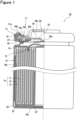
- FIG. 1 is a side and partial sectional view of the cylindrical battery 10 as an example of an embodiment.
- the cylindrical battery 10 comprises a bottomed cylinder-shaped outer housing can 16 including a bottom surface 16a and a side wall 16b, a sealing assembly 17 that seals an opening of the outer housing can 16, and a gasket 18 interposed between the outer housing can 16 and the sealing assembly 17.
- the cylindrical battery 10 comprises an electrode assembly 14 and an electrolyte that are housed in the outer housing can 16.
- the electrode assembly 14 includes a positive electrode 11, a negative electrode 12, and separators 13, and has a structure in which the positive electrode 11 and the negative electrode 12 are wound in a spiral via the separators 13.
- a direction along the axial direction of the outer housing can 16 is assumed to be a "longitudinal direction or up-down direction", and the sealing assembly 17 side (opening side of the outer housing can 16) of the cylindrical battery 10 is assumed to be above and the bottom surface 16a side of the outer housing can 16 is assumed to be below.
- the positive electrode 11 includes a positive electrode core and a positive electrode mixture layer formed on at least one side of the core.
- metal foil stable in a potential range of the positive electrode 11, such as aluminum and an aluminum alloy, a film with the metal disposed on the surface layer, and the like can be used.
- the positive electrode mixture layer includes a positive electrode active material, a conductive agent, such as acetylene black, and a binding agent, such as polyvinylidene difluoride, and is preferably formed on each of opposite sides of the positive electrode core.
- a lithium transition metal composite oxide is used for example.
- the negative electrode 12 includes a negative electrode core and a negative electrode mixture layer formed on at least one side of the core.
- a negative electrode core metal foil stable in a potential range of the negative electrode 12, such as copper and a copper alloy, a film with the metal disposed on the surface layer, and the like can be used.
- the negative electrode mixture layer includes a negative electrode active material and a binding agent, such as styrene butadiene rubber (SBR), and is preferably formed on each of opposite sides of the negative electrode core.
- SBR styrene butadiene rubber
- the negative electrode active material for example, graphite and silicon-containing compound are used.
- the electrolyte may be either an aqueous electrolyte or a non-aqueous electrolyte. Further, the electrolyte may be either a liquid electrolyte or a solid electrolyte. In the present embodiment, a non-aqueous electrolyte is used.
- the non-aqueous electrolyte includes a non-aqueous solvent and electrolyte salt dissolved in the non-aqueous solvent.
- the non-aqueous solvent for example, esters, ethers, nitriles, amides, and a mixed solvent of two or more of these may be used.
- the non-aqueous solvent may contain a halogen-substituted substance formed by replacing at least a portion of hydrogen of these solvents with a halogen atom such as fluorine.
- a halogen atom such as fluorine.
- the electrolyte salt for example, lithium salt such as LiPF 6 is used.
- the cylindrical battery 10 comprises insulating plates 19, 20 that are respectively disposed above and below the electrode assembly 14.
- a positive electrode tab 21 connected to the positive electrode 11 passes through a through-hole of the insulating plate 19 and extends to the sealing assembly 17 side.
- a negative electrode tab 22 is connected to each of an outermost circumference and an innermost circumference of the negative electrode 12, the negative electrode tab 22 connected to the outermost circumference of the negative electrode 12 passing an outer side of the insulating plate 20 and extending to the bottom surface 16a side of the outer housing can 16, the negative electrode tab 22 connected to the innermost circumference of the negative electrode 12 passing through a through-hole of the insulating plate 20 and extending to the bottom surface 16a of the outer housing can 16.
- the positive electrode tab 21 is connected to a terminal plate 25 as a bottom plate of the sealing assembly 17 by welding or the like and a cap 28 of the sealing assembly 17 electrically connected to the terminal plate 25 serves as a positive electrode external terminal.
- the negative electrode tab 22 is connected to an inner surface of the bottom surface 16a of the outer housing can 16 by welding or the like and the outer housing can 16 serves as a negative electrode external terminal. The detailed structure of the sealing assembly 17 will be described later.
- the outer housing can 16 is a metal container opened at one end (upper end) in the axial direction, and the bottom surface 16a is in a disk shape and the side wall 16b is cylindrically formed along an outer circumferential edge of the bottom surface 16a.
- the sealing assembly 17 is formed in a disk shape corresponding to the shape of the opening of the outer housing can 16.
- the gasket 18 is an annular resin member and secures the sealability inside the battery, as well as the electrical insulation between the outer housing can 16 and the sealing assembly 17.
- an opening edge (upper end portion) is inwardly bent so that a staking portion 31 that presses the sealing assembly 17 via the gasket 18 is formed.
- a grooved portion 30, which is configured to support the sealing assembly 17 via the gasket 18, is formed such that the side wall 16b inwardly protrudes from the outer side.
- the grooved portion 30 is annularly formed along the circumferential direction of the outer housing can 16 by externally spinning the side wall 16b.
- the staking portion 31 opposes the grooved portion 30 via the sealing assembly 17 and the gasket 18 and sandwiches the sealing assembly 17 in cooperation with the grooved portion 30.
- the staking portion 31 is, as with the grooved portion 30, annularly formed along the circumferential direction of the outer housing can 16 and presses a circumferential edge of the sealing assembly 17 via the gasket 18 from above.
- the staking portion 31 includes a staking shoulder portion 31a that is the highest portion in the axial direction of the outer housing can 16.
- the sealing assembly 17 is a disk-shaped member including a CID mechanism (current interrupt mechanism).
- the sealing assembly 17 has a structure in which the terminal plate 25, an insulating plate 27, a rupture disk 26, and the cap 28 are stacked in this order from the electrode assembly 14 side.
- the terminal plate 25 is a metal plate including an annular portion to which the positive electrode tab 21 is connected and a thin center portion that is detached from the annular portion when the internal pressure of the battery exceeds a predetermined threshold.
- the rupture disk 26 is disposed opposite to the terminal plate 25 with the insulating plate 27 sandwiched therebetween.
- the rupture disk 26 includes a vent member 26a that ruptures when the internal pressure of the battery exceeds a predetermined threshold, and an outer circumferential portion, which is staked at the staking portion 31, on an outer circumferential side.
- the vent member 26a is connected to the center portion of the terminal plate 25 by welding or the like.
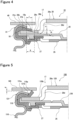
- FIG. 5 is an expanded sectional view of the vicinity of a staking portion 131 in welding a coupling plate 140 at the staking shoulder portion 131a in the cylindrical battery 100.
- the structure of the cylindrical battery 100 with the conventional structure of FIG. 5 , excluding a flange 128b of a cap 128, is the same as that of the cylindrical battery 10 of the present embodiment shown in FIG. 1 .
- the flange 128b of the cap 128 of the cylindrical battery 100 is in a flat annular shape with a uniform plate thickness.
- the staking portion 131 is formed by staking the flange 128b of the cap 128 and the rupture disk 126 at the opening edge of an outer housing can 116 via a gasket 118, which is the same as the example.
- the gasket 118 is pressed against the flange 128b from above and is most deformed. Therefore, a protruding portion 118a of the gasket 118 bounces and rises from the flange 128b with the distal end portion 131b of the staking portion 131 as a starting point.
- the cylindrical battery 10 of the present embodiment comprises the bottomed cylinder-shaped outer housing can 16 that houses the electrode assembly 14 and the sealing assembly 17 fixed by staking via the gasket 18 at the staking portion 31 formed by bending the opening of the outer housing can 16.
- the sealing assembly 17 includes the cap 28 including a projection 28a projecting upward at a center portion and a flange 28b on an outer circumferential side of the projection 28a.
- the flange 28b of the cap 28 includes a recess 28c formed with a thin plate thickness, and the gasket 18 is configured such that a protruding portion 18a protruding from a distal end in the radial direction of the staking portion 31 is housed within the recess 28c.
- the recess 28c of the flange 28b is formed with a thin plate thickness
- a distal end portion 31b of the staking portion 31 presses the gasket 18 so that the distal end of the protruding portion 18a of the gasket 18 deforms so as to be housed within the recess 28c. Therefore, the distal end of the gasket 18 is not positioned above relative to the staking shoulder portion 31a.
- the coupling plate 40 can be contacted with the staking shoulder portion 31a without a gap and thus can be surely welded. With the configuration of the sealing assembly 17 of the present embodiment, it is possible to secure the quality of welding the external terminal.
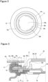
- FIG. 2 is a view of the cylindrical battery 10 of the present embodiment as seen from above.
- FIG. 3 is an expanded sectional view of the vicinity of the staking portion 31 in welding the coupling plate 40 at the staking shoulder portion 31a.
- the staking portion 31 is annularly formed so as to extend radially inward from the opening edge of the outer housing can 16.
- the staking portion 31 presses, by staking, the flange 28b and the rupture disk 26 via the gasket 18.
- the annular recess 28c is formed on the inner circumferential side from the distal end portion 31b on the inner circumferential side of the staking portion 31.
- the gasket 18 includes the protruding portion 18a protruding radially inward from the distal end portion 31b on the inner circumferential side of the staking portion 31.
- the protruding portion 18a of the gasket 18 is housed within the recess 28c of the flange 28b.
- the projection 28a is formed on a further inner circumferential side of the flange 28b.
- a plurality of holes 28d is formed, but this is not an essential configuration.
- the recess 28c is formed so as to satisfy R > r.
- the distal end of the protruding portion 18a of the gasket 18 is surely housed within the recess 28c. Therefore, the protruding portion 18a of the gasket 18 does not rise upward beyond the staking shoulder portion 31a, and in welding the coupling plate 40 at the staking shoulder portion 31a, no gap is generated between the staking shoulder portion 31a and the coupling plate 40. Accordingly, the cylindrical battery 10 of the present embodiment has the structure in which the defect in welding the coupling plate 40 at the staking shoulder portion 31a is suppressed.
- the distal end portion 31b on the inner circumferential side of the staking portion 31 is preferably formed substantially at the same position as that of the edge on the outer circumferential side of the recess 28c. This is because when the edge on the outer circumferential side of the recess 28c is positioned on the inner circumferential side relative to the distal end portion 31b of the staking portion 31, the distal end portion 31b presses the gasket 18 at a flat portion of the flange 28b, which could cause the protruding portion 18a of the gasket 18 to bounce and rise from the flange 28b with the distal end portion 31b as a starting point, in the same manner as in the conventional structure.
- FIG. 4 is an expanded sectional view of the vicinity of the staking portion 31 in welding the coupling plate 40 at the staking shoulder portion 31a in the cylindrical battery 10 of a second embodiment.
- the view of the cylindrical battery 10 of the second embodiment as seen from the above is the same as that of the first embodiment and thus, the illustration will be omitted.
- the cylindrical battery 10 of the second embodiment differs from the cylindrical battery 10 of the first embodiment in the cross-sectional shape of the recess 28c provided in the flange 28b.
- the recess 28c is formed so as to satisfy R > r. With such formation, the distal end of the protruding portion 18a of the gasket 18 is surely housed within the recess 28c.
- the recess 28c of the second embodiment is formed so as to have an inclination with the plate thickness becoming thinner from the edge on the outer circumferential side of the recess 28c toward the inner circumferential side in the radial direction.
- the edge on the outer circumferential side of the recess 28c is formed substantially at the same position as that of the distal end portion 31b on the inner circumferential side of the staking portion 31. Therefore, the gasket 18 of the cylindrical battery 10 of the present embodiment is gradually inclined downward along the inclination of the recess 28c from the distal end portion 31b of the staking portion 31.
- the recess 28c of the second embodiment can suppress rising of the gasket 18, as well as a decline in strength by securing the plate thickness on the outer circumferential side of the flange 28b.
- the sealability of the sealing assembly 17 can still be made high.
- the others were the same as those in Example 1.
- the others were the same as those in Example 1.
- the others were the same as those in Example 1.
- the cylindrical battery 100 having the conventional configuration shown in FIG. 5 was produced. Note that the thickness of the flange 128b was 0.4 mm.
- Table 1 shows the verification results of whether the protruding portions 18a, 118a of the gaskets 18, 118 of the cylindrical batteries 10, 100 in Examples 1 to 4 and the comparative example protruded upward beyond the staking shoulder portions 31a, 131a.
- the protruding portion 18a of the gasket 18 does not protrude upward beyond the staking shoulder portion 31a, and therefore, the performance of welding the coupling plate at the staking shoulder portion is excellent as compared to the cylindrical battery 100 with the conventional structure.
- Electrode assembly 16 Outer housing can, 16a Bottom surface, 16b Side wall, 17 Sealing assembly, 18, 118 Gasket, 18a, 118a Protruding portion, 19 Insulating plate, 20 Insulating plate, 21 Positive electrode tab, 22 Negative electrode tab, 25 Terminal plate, 26, 126 Rupture disk, 27 Insulating plate, 28, 128 Cap, 28a Projection, 28b, 128b Flange, 28c Recess, 28d Hole, 30 Grooved portion, 31, 131 Staking portion, 31a, 131a Staking shoulder portion, 31b, 131b Distal end portion, 40, 140 Coupling plate
Landscapes
- Chemical & Material Sciences (AREA)
- Chemical Kinetics & Catalysis (AREA)
- Electrochemistry (AREA)
- General Chemical & Material Sciences (AREA)
- Sealing Battery Cases Or Jackets (AREA)
Abstract
Description
- The present disclosure relates to a cylindrical battery.
- The application of lithium ion batteries has been broadened to include those on-board and for driving power and storage of electricity. For mounting on products, multiple batteries are connected in series and/or in parallel and are modularized. For electrical connection of the batteries, demand from clients has been increasing for one side surface connection in which a positive side is connected at a positive electrode of the battery on a top surface of a cap and a negative side is connected at a staking portion (staking shoulder portion) of the battery.
- Patent Literature 1 describes a cylindrical battery that is sealed by staking a sealing assembly at an opening of an outer housing can via a gasket.
- PATENT LITERATURE 1:
Japanese Unexamined Patent Application Publication No. 2008-282679 - In a cylindrical battery described in Patent Literature 1 or the like, in welding a coupling plate at a staking shoulder portion through one side surface connection, if there is a gap between the staking shoulder portion and the coupling plate, a welding defect occurs. The cause of the gap generation is that a gasket rises upward beyond the staking shoulder portion and the gasket interferes with the coupling plate. As a countermeasure against this, shortening the gasket protruding from a distal end of the staking portion is conceived. However, when the gasket protruding from the distal end of the staking portion is shortened, the insulating performance between the distal end of the staking portion and a cap could deteriorate.
- It is an advantage of the present disclosure to provide a cylindrical battery capable of securing welding quality without generating a gap between a staking shoulder portion and a coupling plate in welding the coupling plate at the staking shoulder portion.
- A cylindrical battery according to the present disclosure comprises: a bottomed cylinder-shaped outer housing can that houses an electrode assembly; and a sealing assembly fixed by staking, via a gasket, at a staking portion formed by bending an opening of the outer housing can. The sealing assembly includes a cap having a flange staked at the staking portion, the flange of the cap includes a recess formed with a thin plate thickness, and a protruding portion of the gasket is housed in the recess, the protruding portion protruding from a distal end in a radial direction of the staking portion.
- In the cylindrical battery according to the present disclosure, the gasket protruding from the distal end of the staking portion is not positioned above relative to the staking shoulder portion, and therefore, in welding the coupling plate at the staking shoulder portion, no gap is generated between the staking shoulder portion and the coupling plate, thereby being able to secure the welding quality.
-
-
FIG. 1 is a side and partial sectional view of a cylindrical battery of an embodiment. -
FIG. 2 is a plan view of a sealing assembly of the embodiment. -
FIG. 3 is an expanded sectional view of the vicinity of a staking portion in welding a coupling plate at a staking shoulder portion in a cylindrical battery of a first embodiment. -
FIG. 4 is an expanded sectional view of the vicinity of the staking portion in welding the coupling plate at the staking shoulder portion in the cylindrical battery of a second embodiment. -
FIG. 5 is an expanded sectional view of the vicinity of a staking portion in welding a coupling plate at a staking shoulder portion in a conventional cylindrical battery. - Hereinafter, an embodiment of the present disclosure will be described in detail with reference to the drawings. In the following description, the specific shapes, materials, directions, numerical values, and the like are exemplary illustrations for easier understanding of the present disclosure and may be appropriately changed in accordance with applications, purposes, specifications, and the like. Further, it is originally expected that the constituent elements of the embodiments and the modification described below are selectively combined.
- With reference to the drawings, examples of embodiments of a
cylindrical battery 10 according to the present disclosure will be described in detail below.FIG. 1 is a side and partial sectional view of thecylindrical battery 10 as an example of an embodiment. - As shown in
FIG. 1 , thecylindrical battery 10 comprises a bottomed cylinder-shaped outer housing can 16 including abottom surface 16a and aside wall 16b, asealing assembly 17 that seals an opening of the outer housing can 16, and agasket 18 interposed between the outer housing can 16 and thesealing assembly 17. Further, thecylindrical battery 10 comprises anelectrode assembly 14 and an electrolyte that are housed in the outer housing can 16. Theelectrode assembly 14 includes apositive electrode 11, anegative electrode 12, andseparators 13, and has a structure in which thepositive electrode 11 and thenegative electrode 12 are wound in a spiral via theseparators 13. - In the present specification, for convenience of explanation, a direction along the axial direction of the outer housing can 16 is assumed to be a "longitudinal direction or up-down direction", and the
sealing assembly 17 side (opening side of the outer housing can 16) of thecylindrical battery 10 is assumed to be above and thebottom surface 16a side of the outer housing can 16 is assumed to be below. - The
positive electrode 11 includes a positive electrode core and a positive electrode mixture layer formed on at least one side of the core. For the positive electrode core, metal foil stable in a potential range of thepositive electrode 11, such as aluminum and an aluminum alloy, a film with the metal disposed on the surface layer, and the like can be used. The positive electrode mixture layer includes a positive electrode active material, a conductive agent, such as acetylene black, and a binding agent, such as polyvinylidene difluoride, and is preferably formed on each of opposite sides of the positive electrode core. For the positive electrode active material, for example, a lithium transition metal composite oxide is used. - The
negative electrode 12 includes a negative electrode core and a negative electrode mixture layer formed on at least one side of the core. For the negative electrode core, metal foil stable in a potential range of thenegative electrode 12, such as copper and a copper alloy, a film with the metal disposed on the surface layer, and the like can be used. The negative electrode mixture layer includes a negative electrode active material and a binding agent, such as styrene butadiene rubber (SBR), and is preferably formed on each of opposite sides of the negative electrode core. For the negative electrode active material, for example, graphite and silicon-containing compound are used. - The electrolyte may be either an aqueous electrolyte or a non-aqueous electrolyte. Further, the electrolyte may be either a liquid electrolyte or a solid electrolyte. In the present embodiment, a non-aqueous electrolyte is used. The non-aqueous electrolyte includes a non-aqueous solvent and electrolyte salt dissolved in the non-aqueous solvent. For the non-aqueous solvent, for example, esters, ethers, nitriles, amides, and a mixed solvent of two or more of these may be used. The non-aqueous solvent may contain a halogen-substituted substance formed by replacing at least a portion of hydrogen of these solvents with a halogen atom such as fluorine. For the electrolyte salt, for example, lithium salt such as LiPF6 is used.
- The
cylindrical battery 10 comprisesinsulating plates electrode assembly 14. In the example shown inFIG. 1 , apositive electrode tab 21 connected to thepositive electrode 11 passes through a through-hole of theinsulating plate 19 and extends to thesealing assembly 17 side. Anegative electrode tab 22 is connected to each of an outermost circumference and an innermost circumference of thenegative electrode 12, thenegative electrode tab 22 connected to the outermost circumference of thenegative electrode 12 passing an outer side of theinsulating plate 20 and extending to thebottom surface 16a side of the outer housing can 16, thenegative electrode tab 22 connected to the innermost circumference of thenegative electrode 12 passing through a through-hole of theinsulating plate 20 and extending to thebottom surface 16a of the outer housing can 16. Thepositive electrode tab 21 is connected to aterminal plate 25 as a bottom plate of thesealing assembly 17 by welding or the like and acap 28 of thesealing assembly 17 electrically connected to theterminal plate 25 serves as a positive electrode external terminal. Thenegative electrode tab 22 is connected to an inner surface of thebottom surface 16a of the outer housing can 16 by welding or the like and the outer housing can 16 serves as a negative electrode external terminal. The detailed structure of thesealing assembly 17 will be described later. - The outer housing can 16 is a metal container opened at one end (upper end) in the axial direction, and the
bottom surface 16a is in a disk shape and theside wall 16b is cylindrically formed along an outer circumferential edge of thebottom surface 16a. Thesealing assembly 17 is formed in a disk shape corresponding to the shape of the opening of the outer housing can 16. Thegasket 18 is an annular resin member and secures the sealability inside the battery, as well as the electrical insulation between the outer housing can 16 and thesealing assembly 17. - In the outer housing can 16, an opening edge (upper end portion) is inwardly bent so that a
staking portion 31 that presses thesealing assembly 17 via thegasket 18 is formed. Further, in the outer housing can 16, agrooved portion 30, which is configured to support thesealing assembly 17 via thegasket 18, is formed such that theside wall 16b inwardly protrudes from the outer side. Thegrooved portion 30 is annularly formed along the circumferential direction of the outer housing can 16 by externally spinning theside wall 16b. - The
staking portion 31 opposes thegrooved portion 30 via thesealing assembly 17 and thegasket 18 and sandwiches thesealing assembly 17 in cooperation with the groovedportion 30. Thestaking portion 31 is, as with thegrooved portion 30, annularly formed along the circumferential direction of the outer housing can 16 and presses a circumferential edge of thesealing assembly 17 via thegasket 18 from above. Thestaking portion 31 includes astaking shoulder portion 31a that is the highest portion in the axial direction of the outer housing can 16. - The sealing
assembly 17 is a disk-shaped member including a CID mechanism (current interrupt mechanism). The sealingassembly 17 has a structure in which theterminal plate 25, an insulatingplate 27, arupture disk 26, and thecap 28 are stacked in this order from theelectrode assembly 14 side. Theterminal plate 25 is a metal plate including an annular portion to which thepositive electrode tab 21 is connected and a thin center portion that is detached from the annular portion when the internal pressure of the battery exceeds a predetermined threshold. - The
rupture disk 26 is disposed opposite to theterminal plate 25 with the insulatingplate 27 sandwiched therebetween. Therupture disk 26 includes avent member 26a that ruptures when the internal pressure of the battery exceeds a predetermined threshold, and an outer circumferential portion, which is staked at the stakingportion 31, on an outer circumferential side. Thevent member 26a is connected to the center portion of theterminal plate 25 by welding or the like. When an abnormal condition occurs in the battery and the internal pressure increases to exceed an operating pressure of the CID mechanism, theterminal plate 25 ruptures and the center portion is detached from the annular portion, so that thevent member 26a deforms in such a manner as projecting to the outer side of the battery. As a result, the current path is disconnected. When the internal pressure of the battery further increases to exceed a vent pressure, thevent member 26a ruptures so that a gas discharge port is formed. - Here, description will be made of the cause of a welding defect of a staking
shoulder portion 131a in acylindrical battery 100 with a conventional structure.FIG. 5 is an expanded sectional view of the vicinity of a stakingportion 131 in welding acoupling plate 140 at the stakingshoulder portion 131a in thecylindrical battery 100. - The structure of the
cylindrical battery 100 with the conventional structure ofFIG. 5 , excluding aflange 128b of acap 128, is the same as that of thecylindrical battery 10 of the present embodiment shown inFIG. 1 . Theflange 128b of thecap 128 of thecylindrical battery 100 is in a flat annular shape with a uniform plate thickness. - In the
cylindrical battery 100 with the conventional structure, the stakingportion 131 is formed by staking theflange 128b of thecap 128 and therupture disk 126 at the opening edge of an outer housing can 116 via agasket 118, which is the same as the example. In thecylindrical battery 100 with the conventional structure, at adistal end portion 131b on an inner circumferential side in a radial direction of the stakingportion 131, thegasket 118 is pressed against theflange 128b from above and is most deformed. Therefore, a protrudingportion 118a of thegasket 118 bounces and rises from theflange 128b with thedistal end portion 131b of the stakingportion 131 as a starting point. Thus, when the length in the radial direction of the protrudingportion 118a of thegasket 118 is long, a distal end of the protrudingportion 118a of thegasket 118 is positioned above beyond the stakingshoulder portion 131a. - In the
cylindrical battery 100 with such a state, in welding thecoupling plate 140 at the stakingshoulder portion 131a, the distal end of the protrudingportion 118a of thegasket 118 interferes with thecoupling plate 140, so that a gap d is generated between thecoupling plate 140 and the stakingshoulder portion 131a as shown inFIG. 5 . Accordingly, due to the presence of the gap d, a defect in welding between thecoupling plate 140 and the stakingshoulder portion 131a could occasionally occurs. - Next, with reference to
FIG. 1 , description will be made of the reason why the welding defect of acoupling plate 40 is suppressed in the structure of the sealingassembly 17 of thecylindrical battery 10 of the first embodiment. - The
cylindrical battery 10 of the present embodiment comprises the bottomed cylinder-shaped outer housing can 16 that houses theelectrode assembly 14 and the sealingassembly 17 fixed by staking via thegasket 18 at the stakingportion 31 formed by bending the opening of the outer housing can 16. The sealingassembly 17 includes thecap 28 including aprojection 28a projecting upward at a center portion and aflange 28b on an outer circumferential side of theprojection 28a. Theflange 28b of thecap 28 includes arecess 28c formed with a thin plate thickness, and thegasket 18 is configured such that a protrudingportion 18a protruding from a distal end in the radial direction of the stakingportion 31 is housed within therecess 28c. - In the
cylindrical battery 10 of the present embodiment, since therecess 28c of theflange 28b is formed with a thin plate thickness, adistal end portion 31b of the stakingportion 31 presses thegasket 18 so that the distal end of the protrudingportion 18a of thegasket 18 deforms so as to be housed within therecess 28c. Therefore, the distal end of thegasket 18 is not positioned above relative to the stakingshoulder portion 31a. In connecting thecylindrical battery 10 to an external terminal, thecoupling plate 40 can be contacted with the stakingshoulder portion 31a without a gap and thus can be surely welded. With the configuration of the sealingassembly 17 of the present embodiment, it is possible to secure the quality of welding the external terminal. - With reference to
FIGS. 2 and 3 , further description will be made of the structures of the sealingassembly 17 and the stakingportion 31 of thecylindrical battery 10 of the present embodiment.FIG. 2 is a view of thecylindrical battery 10 of the present embodiment as seen from above.FIG. 3 is an expanded sectional view of the vicinity of the stakingportion 31 in welding thecoupling plate 40 at the stakingshoulder portion 31a. - The staking
portion 31 is annularly formed so as to extend radially inward from the opening edge of the outer housing can 16. The stakingportion 31 presses, by staking, theflange 28b and therupture disk 26 via thegasket 18. In theflange 28b, theannular recess 28c is formed on the inner circumferential side from thedistal end portion 31b on the inner circumferential side of the stakingportion 31. Thegasket 18 includes the protrudingportion 18a protruding radially inward from thedistal end portion 31b on the inner circumferential side of the stakingportion 31. The protrudingportion 18a of thegasket 18 is housed within therecess 28c of theflange 28b. On a further inner circumferential side of theflange 28b, theprojection 28a is formed. In theprojection 28a, a plurality ofholes 28d is formed, but this is not an essential configuration. - As shown in
FIG. 3 , when a length in the radial direction of the protrudingportion 18a of thegasket 18 is assumed to be r and a length in the radial direction of therecess 28c is assumed to be R, therecess 28c is formed so as to satisfy R > r. With such formation, the distal end of the protrudingportion 18a of thegasket 18 is surely housed within therecess 28c. Therefore, the protrudingportion 18a of thegasket 18 does not rise upward beyond the stakingshoulder portion 31a, and in welding thecoupling plate 40 at the stakingshoulder portion 31a, no gap is generated between the stakingshoulder portion 31a and thecoupling plate 40. Accordingly, thecylindrical battery 10 of the present embodiment has the structure in which the defect in welding thecoupling plate 40 at the stakingshoulder portion 31a is suppressed. - The
distal end portion 31b on the inner circumferential side of the stakingportion 31 is preferably formed substantially at the same position as that of the edge on the outer circumferential side of therecess 28c. This is because when the edge on the outer circumferential side of therecess 28c is positioned on the inner circumferential side relative to thedistal end portion 31b of the stakingportion 31, thedistal end portion 31b presses thegasket 18 at a flat portion of theflange 28b, which could cause the protrudingportion 18a of thegasket 18 to bounce and rise from theflange 28b with thedistal end portion 31b as a starting point, in the same manner as in the conventional structure. -
FIG. 4 is an expanded sectional view of the vicinity of the stakingportion 31 in welding thecoupling plate 40 at the stakingshoulder portion 31a in thecylindrical battery 10 of a second embodiment. The view of thecylindrical battery 10 of the second embodiment as seen from the above is the same as that of the first embodiment and thus, the illustration will be omitted. Thecylindrical battery 10 of the second embodiment differs from thecylindrical battery 10 of the first embodiment in the cross-sectional shape of therecess 28c provided in theflange 28b. - In the present embodiment as well, when the length in the radial direction of the protruding
portion 18a of thegasket 18 is assumed to be r and the length in the radial direction of therecess 28c is assumed to be R, therecess 28c is formed so as to satisfy R > r. With such formation, the distal end of the protrudingportion 18a of thegasket 18 is surely housed within therecess 28c. - Further, the
recess 28c of the second embodiment is formed so as to have an inclination with the plate thickness becoming thinner from the edge on the outer circumferential side of therecess 28c toward the inner circumferential side in the radial direction. The edge on the outer circumferential side of therecess 28c is formed substantially at the same position as that of thedistal end portion 31b on the inner circumferential side of the stakingportion 31. Therefore, thegasket 18 of thecylindrical battery 10 of the present embodiment is gradually inclined downward along the inclination of therecess 28c from thedistal end portion 31b of the stakingportion 31. - With the inclination provided, the
recess 28c of the second embodiment can suppress rising of thegasket 18, as well as a decline in strength by securing the plate thickness on the outer circumferential side of theflange 28b. - Further, in the
recess 28c of the second embodiment, since the inclination with the plate thickness gradually becoming thinner from the vicinity of thedistal end portion 31b of the stakingportion 31 is formed, even when the position of thedistal end portion 31b of the stakingportion 31 is shifted to the inner side in the radial direction, the sealability of the sealingassembly 17 can still be made high. - As described above, in the
cylindrical battery 10 of the present disclosure, with therecess 28c provided in theflange 28b of thecap 28, rising of the protrudingportion 18a of thegasket 18 upward beyond the stakingshoulder portion 31a after staking the outer housing can 16 is suppressed. Thus, since it is unnecessary to shorten the protrudingportion 18a of thegasket 18 protruding from the stakingportion 31, it is less likely to deteriorate the insulating performance between thedistal end portion 31b of the stakingportion 31 and thecap 28, so that the welding quality in welding thecoupling plate 40 at the stakingshoulder portion 31a can be secured. - Next, using examples, description will be made of results of verifying suppression of the
gasket 18 protruding upward beyond the stakingportion 31 in thecylindrical battery 10 of the present disclosure. Thecylindrical battery 10 under the following conditions was produced and whether thegasket 18 protrudes upward beyond the stakingshoulder portion 31a was verified. A hundredcylindrical batteries 10 and a hundredcylindrical batteries 100 were each produced for Examples 1 to 4 and a comparative example. - For the
cylindrical battery 10 of the first embodiment shown inFIG. 3 , thecylindrical battery 10 having therecess 28c with the length R in the radial direction = 1.3 mm and a depth h = 0.10 mm was produced. Note that the thickness of theflange 28b was 0.4 mm. - For the
cylindrical battery 10 of the first embodiment shown inFIG. 3 , thecylindrical battery 10 having therecess 28c with the length R in the radial direction = 1.3 mm and the depth h = 0.15 mm was produced. The others were the same as those in Example 1. - For the
cylindrical battery 10 of the second embodiment shown inFIG. 4 , thecylindrical battery 10 having therecess 28c with an inclination angle θ = 10°, the length R in the radial direction = 1.3 mm, and the depth h = 0.23 mm was produced. The others were the same as those in Example 1. - For the
cylindrical battery 10 of the second embodiment shown inFIG. 4 , thecylindrical battery 10 having therecess 28c with the inclination angle θ = 12°, the length R in the radial direction = 1.3 mm, and the depth h = 0.28 mm was produced. The others were the same as those in Example 1. - As a comparative example, the
cylindrical battery 100 having the conventional configuration shown inFIG. 5 was produced. Note that the thickness of theflange 128b was 0.4 mm. - Table 1 shows the verification results of whether the protruding
portions gaskets cylindrical batteries shoulder portions [Table 1] LENGTH R IN RADIAL DIRECTION INCLINATION ANGLE θ DEPTH h NUMBER OF GASKETS PROTRUDING UPWARD BEYOND STAKING SHOULDER PORTION EXAMPLE 1 1.3mm --- 0.10mm 0/100 EXAMPLE 2 1.3mm --- 0.15mm 0/100 EXAMPLE 3 1.3 mm 10° 0.23mm 0/100 EXAMPLE 4 1.3 mm 12° 0.28mm 0/100 COMPARATIVE EXAMPLE 4/100 - In the
cylindrical battery 10 of Examples 1 and 2, no protrudingportion 18a of thegasket 18 protruding upward beyond the stakingshoulder portion 31a was confirmed, irrespective of the depth h of therecess 28c of theflange 28b. In thecylindrical battery 10 of Examples 3 and 4, no protrudingportion 18a of thegasket 18 protruding upward beyond the stakingshoulder portion 31a was confirmed, irrespective of whether the inclination angle θ of therecess 28c of theflange 28b was 10° or 12°. By contrast, in thecylindrical battery 100 of the comparative example, in 4 out of 100, the protrudingportion 118a of thegasket 118 protruding upward beyond the stakingshoulder portion 131a was confirmed. - It is recognized from the above results that in the
cylindrical battery 10 of the present disclosure, the protrudingportion 18a of thegasket 18 does not protrude upward beyond the stakingshoulder portion 31a, and therefore, the performance of welding the coupling plate at the staking shoulder portion is excellent as compared to thecylindrical battery 100 with the conventional structure. - Note that it goes without saying that the present invention is not limited to the aforementioned embodiments and modifications thereof, and various changes and improvements are available within the scope of the matters described in the claims of the present application.
- 10, 100 Cylindrical battery, 11 Positive electrode, 12 Negative electrode, 13 Separator, 14 Electrode assembly, 16 Outer housing can, 16a Bottom surface, 16b Side wall, 17 Sealing assembly, 18, 118 Gasket, 18a, 118a Protruding portion, 19 Insulating plate, 20 Insulating plate, 21 Positive electrode tab, 22 Negative electrode tab, 25 Terminal plate, 26, 126 Rupture disk, 27 Insulating plate, 28, 128 Cap, 28a Projection, 28b, 128b Flange, 28c Recess, 28d Hole, 30 Grooved portion, 31, 131 Staking portion, 31a, 131a Staking shoulder portion, 31b, 131b Distal end portion, 40, 140 Coupling plate
Claims (3)
- A cylindrical battery comprising:a bottomed cylinder-shaped outer housing can that houses an electrode assembly; anda sealing assembly fixed by staking, via a gasket, at a staking portion formed by bending an opening of the outer housing can, whereinthe sealing assembly includes a cap having a flange staked at the staking portion,the flange of the cap includes a recess formed with a thin plate thickness, anda protruding portion of the gasket is housed in the recess, the protruding portion protruding from a distal end in a radial direction of the staking portion.
- The cylindrical battery according to claim 1, wherein the recess comprises an inclination with a plate thickness becoming thinner toward an inner circumferential side in a radial direction of the flange.
- The cylindrical battery according to claim 1 or 2, wherein when a length in a radial direction of the protruding portion of the gasket is r and a length in a radial direction of the recess is R, the recess is formed so as to satisfy R > r.
Applications Claiming Priority (2)
| Application Number | Priority Date | Filing Date | Title |
|---|---|---|---|
| JP2022033213 | 2022-03-04 | ||
| PCT/JP2023/005675 WO2023167010A1 (en) | 2022-03-04 | 2023-02-17 | Cylindrical battery |
Publications (2)
| Publication Number | Publication Date |
|---|---|
| EP4489214A1 true EP4489214A1 (en) | 2025-01-08 |
| EP4489214A4 EP4489214A4 (en) | 2025-06-11 |
Family
ID=87883473
Family Applications (1)
| Application Number | Title | Priority Date | Filing Date |
|---|---|---|---|
| EP23763269.0A Pending EP4489214A4 (en) | 2022-03-04 | 2023-02-17 | CYLINDRICAL BATTERY |
Country Status (5)
| Country | Link |
|---|---|
| US (1) | US20250183429A1 (en) |
| EP (1) | EP4489214A4 (en) |
| JP (1) | JPWO2023167010A1 (en) |
| CN (1) | CN118765462A (en) |
| WO (1) | WO2023167010A1 (en) |
Families Citing this family (2)
| Publication number | Priority date | Publication date | Assignee | Title |
|---|---|---|---|---|
| WO2025204942A1 (en) * | 2024-03-29 | 2025-10-02 | パナソニックIpマネジメント株式会社 | Cylindrical battery |
| JP2026068637A (en) * | 2024-10-10 | 2026-04-22 | トヨタ自動車株式会社 | Energy storage device |
Family Cites Families (9)
| Publication number | Priority date | Publication date | Assignee | Title |
|---|---|---|---|---|
| FR2357076A1 (en) * | 1976-06-30 | 1978-01-27 | Cipel | CYLINDRICAL ELECTROCHEMICAL GENERATOR |
| JP2001291498A (en) * | 2000-04-10 | 2001-10-19 | Sony Corp | Sealed battery |
| JP2006351512A (en) * | 2005-05-16 | 2006-12-28 | Matsushita Electric Ind Co Ltd | Sealed secondary battery and method for manufacturing the same |
| JP5110958B2 (en) | 2007-05-10 | 2012-12-26 | 三洋電機株式会社 | Sealed battery |
| KR102096430B1 (en) * | 2015-01-15 | 2020-04-02 | 엘에스엠트론 주식회사 | External terminal member of electric energy storage device having structure for preventing electrolyte leakage |
| KR102063462B1 (en) * | 2016-12-22 | 2020-01-08 | 주식회사 엘지화학 | Device Having Secondary Crimping Mold for Manufacturing Cylindrical Battery Cell |
| CN113228406A (en) * | 2018-12-27 | 2021-08-06 | 三洋电机株式会社 | Cylindrical battery |
| JP7422680B2 (en) * | 2018-12-28 | 2024-01-26 | パナソニックエナジー株式会社 | Gasket and cylindrical battery |
| KR102746304B1 (en) * | 2019-05-08 | 2024-12-26 | 주식회사 엘지에너지솔루션 | Gasket for a Cylindrical Battery to Prevent Corrosion of Battery Case and Cylindrical Battery Comprising the Same |
-
2023
- 2023-02-17 CN CN202380023875.0A patent/CN118765462A/en active Pending
- 2023-02-17 EP EP23763269.0A patent/EP4489214A4/en active Pending
- 2023-02-17 WO PCT/JP2023/005675 patent/WO2023167010A1/en not_active Ceased
- 2023-02-17 US US18/841,217 patent/US20250183429A1/en active Pending
- 2023-02-17 JP JP2024504608A patent/JPWO2023167010A1/ja active Pending
Also Published As
| Publication number | Publication date |
|---|---|
| WO2023167010A1 (en) | 2023-09-07 |
| CN118765462A (en) | 2024-10-11 |
| JPWO2023167010A1 (en) | 2023-09-07 |
| US20250183429A1 (en) | 2025-06-05 |
| EP4489214A4 (en) | 2025-06-11 |
Similar Documents
| Publication | Publication Date | Title |
|---|---|---|
| EP2903056B1 (en) | Rectangular secondary battery | |
| US10665827B2 (en) | Cap assembly for a second battery and second battery | |
| EP3322001B1 (en) | Secondary battery and battery module | |
| KR101627626B1 (en) | Rechargeable battery | |
| US6777128B2 (en) | Secondary battery and fabrication method thereof | |
| US20250183429A1 (en) | Cylindrical battery | |
| US20240322406A1 (en) | Cylindrical battery | |
| US20220231357A1 (en) | Cylindrical battery | |
| US20230187746A1 (en) | Cylindrical battery | |
| CN106328857A (en) | Secondary battery and battery module | |
| EP4250440B1 (en) | Cylindrical battery | |
| US20240387966A1 (en) | Cylindrical battery | |
| US20240204338A1 (en) | Cylindrical battery | |
| US20240014473A1 (en) | Cylindrical battery | |
| WO2024161945A1 (en) | Cylindrical battery | |
| US12463235B2 (en) | Cylindrical battery | |
| JP2011175833A (en) | Cylindrical secondary battery | |
| US20250202030A1 (en) | Cylindrical battery and manufacturing method thereof | |
| EP4675773A1 (en) | Power storage device | |
| EP4675781A1 (en) | Power storage device | |
| EP4675775A1 (en) | Power storage device | |
| EP4675774A1 (en) | Power storage device | |
| EP4679615A1 (en) | Cylindrical battery | |
| WO2024203592A1 (en) | Cylindrical battery and method for manufacturing cylindrical battery |
Legal Events
| Date | Code | Title | Description |
|---|---|---|---|
| STAA | Information on the status of an ep patent application or granted ep patent |
Free format text: STATUS: THE INTERNATIONAL PUBLICATION HAS BEEN MADE |
|
| PUAI | Public reference made under article 153(3) epc to a published international application that has entered the european phase |
Free format text: ORIGINAL CODE: 0009012 |
|
| STAA | Information on the status of an ep patent application or granted ep patent |
Free format text: STATUS: REQUEST FOR EXAMINATION WAS MADE |
|
| 17P | Request for examination filed |
Effective date: 20240827 |
|
| AK | Designated contracting states |
Kind code of ref document: A1 Designated state(s): AL AT BE BG CH CY CZ DE DK EE ES FI FR GB GR HR HU IE IS IT LI LT LU LV MC ME MK MT NL NO PL PT RO RS SE SI SK SM TR |
|
| A4 | Supplementary search report drawn up and despatched |
Effective date: 20250514 |
|
| DAV | Request for validation of the european patent (deleted) | ||
| DAX | Request for extension of the european patent (deleted) | ||
| RIC1 | Information provided on ipc code assigned before grant |
Ipc: H01M 50/567 20210101ALI20250508BHEP Ipc: H01M 50/548 20210101ALI20250508BHEP Ipc: H01M 50/545 20210101ALI20250508BHEP Ipc: H01M 50/184 20210101ALI20250508BHEP Ipc: H01M 50/179 20210101ALI20250508BHEP Ipc: H01M 50/167 20210101ALI20250508BHEP Ipc: H01M 50/152 20210101ALI20250508BHEP Ipc: H01M 50/107 20210101ALI20250508BHEP Ipc: H01M 50/559 20210101AFI20250508BHEP |