EP4489204A1 - Electric power storage module - Google Patents
Electric power storage module Download PDFInfo
- Publication number
- EP4489204A1 EP4489204A1 EP23759911.3A EP23759911A EP4489204A1 EP 4489204 A1 EP4489204 A1 EP 4489204A1 EP 23759911 A EP23759911 A EP 23759911A EP 4489204 A1 EP4489204 A1 EP 4489204A1
- Authority
- EP
- European Patent Office
- Prior art keywords
- protrusions
- face
- power storage
- holder
- storage module
- Prior art date
- Legal status (The legal status is an assumption and is not a legal conclusion. Google has not performed a legal analysis and makes no representation as to the accuracy of the status listed.)
- Pending
Links
Images




Classifications
-
- H—ELECTRICITY
- H01—ELECTRIC ELEMENTS
- H01G—CAPACITORS; CAPACITORS, RECTIFIERS, DETECTORS, SWITCHING DEVICES, LIGHT-SENSITIVE OR TEMPERATURE-SENSITIVE DEVICES OF THE ELECTROLYTIC TYPE
- H01G11/00—Hybrid capacitors, i.e. capacitors having different positive and negative electrodes; Electric double-layer [EDL] capacitors; Processes for the manufacture thereof or of parts thereof
- H01G11/10—Multiple hybrid or EDL capacitors, e.g. arrays or modules
-
- H—ELECTRICITY
- H01—ELECTRIC ELEMENTS
- H01M—PROCESSES OR MEANS, e.g. BATTERIES, FOR THE DIRECT CONVERSION OF CHEMICAL ENERGY INTO ELECTRICAL ENERGY
- H01M50/00—Constructional details or processes of manufacture of the non-active parts of electrochemical cells other than fuel cells, e.g. hybrid cells
- H01M50/20—Mountings; Secondary casings or frames; Racks, modules or packs; Suspension devices; Shock absorbers; Transport or carrying devices; Holders
- H01M50/233—Mountings; Secondary casings or frames; Racks, modules or packs; Suspension devices; Shock absorbers; Transport or carrying devices; Holders characterised by physical properties of casings or racks, e.g. dimensions
- H01M50/242—Mountings; Secondary casings or frames; Racks, modules or packs; Suspension devices; Shock absorbers; Transport or carrying devices; Holders characterised by physical properties of casings or racks, e.g. dimensions adapted for protecting batteries against vibrations, collision impact or swelling
-
- H—ELECTRICITY
- H01—ELECTRIC ELEMENTS
- H01G—CAPACITORS; CAPACITORS, RECTIFIERS, DETECTORS, SWITCHING DEVICES, LIGHT-SENSITIVE OR TEMPERATURE-SENSITIVE DEVICES OF THE ELECTROLYTIC TYPE
- H01G11/00—Hybrid capacitors, i.e. capacitors having different positive and negative electrodes; Electric double-layer [EDL] capacitors; Processes for the manufacture thereof or of parts thereof
- H01G11/14—Arrangements or processes for adjusting or protecting hybrid or EDL capacitors
- H01G11/18—Arrangements or processes for adjusting or protecting hybrid or EDL capacitors against thermal overloads, e.g. heating, cooling or ventilating
-
- H—ELECTRICITY
- H01—ELECTRIC ELEMENTS
- H01G—CAPACITORS; CAPACITORS, RECTIFIERS, DETECTORS, SWITCHING DEVICES, LIGHT-SENSITIVE OR TEMPERATURE-SENSITIVE DEVICES OF THE ELECTROLYTIC TYPE
- H01G11/00—Hybrid capacitors, i.e. capacitors having different positive and negative electrodes; Electric double-layer [EDL] capacitors; Processes for the manufacture thereof or of parts thereof
- H01G11/78—Cases; Housings; Encapsulations; Mountings
-
- H—ELECTRICITY
- H01—ELECTRIC ELEMENTS
- H01G—CAPACITORS; CAPACITORS, RECTIFIERS, DETECTORS, SWITCHING DEVICES, LIGHT-SENSITIVE OR TEMPERATURE-SENSITIVE DEVICES OF THE ELECTROLYTIC TYPE
- H01G11/00—Hybrid capacitors, i.e. capacitors having different positive and negative electrodes; Electric double-layer [EDL] capacitors; Processes for the manufacture thereof or of parts thereof
- H01G11/78—Cases; Housings; Encapsulations; Mountings
- H01G11/82—Fixing or assembling a capacitive element in a housing, e.g. mounting electrodes, current collectors or terminals in containers or encapsulations
-
- H—ELECTRICITY
- H01—ELECTRIC ELEMENTS
- H01M—PROCESSES OR MEANS, e.g. BATTERIES, FOR THE DIRECT CONVERSION OF CHEMICAL ENERGY INTO ELECTRICAL ENERGY
- H01M50/00—Constructional details or processes of manufacture of the non-active parts of electrochemical cells other than fuel cells, e.g. hybrid cells
- H01M50/20—Mountings; Secondary casings or frames; Racks, modules or packs; Suspension devices; Shock absorbers; Transport or carrying devices; Holders
- H01M50/204—Racks, modules or packs for multiple batteries or multiple cells
-
- H—ELECTRICITY
- H01—ELECTRIC ELEMENTS
- H01M—PROCESSES OR MEANS, e.g. BATTERIES, FOR THE DIRECT CONVERSION OF CHEMICAL ENERGY INTO ELECTRICAL ENERGY
- H01M50/00—Constructional details or processes of manufacture of the non-active parts of electrochemical cells other than fuel cells, e.g. hybrid cells
- H01M50/20—Mountings; Secondary casings or frames; Racks, modules or packs; Suspension devices; Shock absorbers; Transport or carrying devices; Holders
- H01M50/204—Racks, modules or packs for multiple batteries or multiple cells
- H01M50/207—Racks, modules or packs for multiple batteries or multiple cells characterised by their shape
- H01M50/213—Racks, modules or packs for multiple batteries or multiple cells characterised by their shape adapted for cells having curved cross-section, e.g. round or elliptic
-
- H—ELECTRICITY
- H01—ELECTRIC ELEMENTS
- H01M—PROCESSES OR MEANS, e.g. BATTERIES, FOR THE DIRECT CONVERSION OF CHEMICAL ENERGY INTO ELECTRICAL ENERGY
- H01M50/00—Constructional details or processes of manufacture of the non-active parts of electrochemical cells other than fuel cells, e.g. hybrid cells
- H01M50/20—Mountings; Secondary casings or frames; Racks, modules or packs; Suspension devices; Shock absorbers; Transport or carrying devices; Holders
- H01M50/244—Secondary casings; Racks; Suspension devices; Carrying devices; Holders characterised by their mounting method
-
- H—ELECTRICITY
- H01—ELECTRIC ELEMENTS
- H01M—PROCESSES OR MEANS, e.g. BATTERIES, FOR THE DIRECT CONVERSION OF CHEMICAL ENERGY INTO ELECTRICAL ENERGY
- H01M50/00—Constructional details or processes of manufacture of the non-active parts of electrochemical cells other than fuel cells, e.g. hybrid cells
- H01M50/20—Mountings; Secondary casings or frames; Racks, modules or packs; Suspension devices; Shock absorbers; Transport or carrying devices; Holders
- H01M50/271—Lids or covers for the racks or secondary casings
- H01M50/273—Lids or covers for the racks or secondary casings characterised by the material
- H01M50/276—Inorganic material
-
- H—ELECTRICITY
- H01—ELECTRIC ELEMENTS
- H01M—PROCESSES OR MEANS, e.g. BATTERIES, FOR THE DIRECT CONVERSION OF CHEMICAL ENERGY INTO ELECTRICAL ENERGY
- H01M50/00—Constructional details or processes of manufacture of the non-active parts of electrochemical cells other than fuel cells, e.g. hybrid cells
- H01M50/20—Mountings; Secondary casings or frames; Racks, modules or packs; Suspension devices; Shock absorbers; Transport or carrying devices; Holders
- H01M50/289—Mountings; Secondary casings or frames; Racks, modules or packs; Suspension devices; Shock absorbers; Transport or carrying devices; Holders characterised by spacing elements or positioning means within frames, racks or packs
-
- H—ELECTRICITY
- H01—ELECTRIC ELEMENTS
- H01M—PROCESSES OR MEANS, e.g. BATTERIES, FOR THE DIRECT CONVERSION OF CHEMICAL ENERGY INTO ELECTRICAL ENERGY
- H01M50/00—Constructional details or processes of manufacture of the non-active parts of electrochemical cells other than fuel cells, e.g. hybrid cells
- H01M50/30—Arrangements for facilitating escape of gases
- H01M50/342—Non-re-sealable arrangements
- H01M50/3425—Non-re-sealable arrangements in the form of rupturable membranes or weakened parts, e.g. pierced with the aid of a sharp member
-
- H—ELECTRICITY
- H01—ELECTRIC ELEMENTS
- H01M—PROCESSES OR MEANS, e.g. BATTERIES, FOR THE DIRECT CONVERSION OF CHEMICAL ENERGY INTO ELECTRICAL ENERGY
- H01M50/00—Constructional details or processes of manufacture of the non-active parts of electrochemical cells other than fuel cells, e.g. hybrid cells
- H01M50/30—Arrangements for facilitating escape of gases
- H01M50/35—Gas exhaust passages comprising elongated, tortuous or labyrinth-shaped exhaust passages
-
- H—ELECTRICITY
- H01—ELECTRIC ELEMENTS
- H01M—PROCESSES OR MEANS, e.g. BATTERIES, FOR THE DIRECT CONVERSION OF CHEMICAL ENERGY INTO ELECTRICAL ENERGY
- H01M50/00—Constructional details or processes of manufacture of the non-active parts of electrochemical cells other than fuel cells, e.g. hybrid cells
- H01M50/30—Arrangements for facilitating escape of gases
- H01M50/35—Gas exhaust passages comprising elongated, tortuous or labyrinth-shaped exhaust passages
- H01M50/367—Internal gas exhaust passages forming part of the battery cover or case; Double cover vent systems
-
- Y—GENERAL TAGGING OF NEW TECHNOLOGICAL DEVELOPMENTS; GENERAL TAGGING OF CROSS-SECTIONAL TECHNOLOGIES SPANNING OVER SEVERAL SECTIONS OF THE IPC; TECHNICAL SUBJECTS COVERED BY FORMER USPC CROSS-REFERENCE ART COLLECTIONS [XRACs] AND DIGESTS
- Y02—TECHNOLOGIES OR APPLICATIONS FOR MITIGATION OR ADAPTATION AGAINST CLIMATE CHANGE
- Y02E—REDUCTION OF GREENHOUSE GAS [GHG] EMISSIONS, RELATED TO ENERGY GENERATION, TRANSMISSION OR DISTRIBUTION
- Y02E60/00—Enabling technologies; Technologies with a potential or indirect contribution to GHG emissions mitigation
- Y02E60/10—Energy storage using batteries
Definitions
- the present disclosure relates to a power storage module.
- a power storage device is prepared for such a situation by including an exhaust valve.
- the exhaust valve opens and releases gas, thus preventing the internal pressure of the power storage device from rising above a predetermined level.
- the power storage module can have, inside the case, a passage for the gas released from each of the power storage devices. This passage for exhaust gas flow inside the case may be blocked, particularly when there is an external impact.
- a battery pack described in PTL 1 uses plural secondary cells, which are exemplary power storage devices, and includes an exhaust duct and an exhaust port for emitting the gas released from the plural power storage devices, with a noise reduction part provided at the exhaust port.
- PTL 1 Japanese Patent Application Laid-open No. 2011-204574
- the exhaust valves of the power storage devices may be obstructed, for example, by an upper cover of the exhaust duct.
- the power storage devices obstructed by the upper cover or the like cannot perform sufficient gas release and can make it difficult for their internal pressure to increase.
- a power storage module includes a holder that includes a plurality of housing parts housing a plurality of power storage devices, each with an exhaust valve, and a plurality of through holes connecting the plurality of housing parts and an outside; and a duct cover covering an end face of the holder where the exhaust valves of the plurality of power storage devices are exposed through the plurality of through holes and forming a gas flow passage with the end face.
- the duct cover includes a plurality of protrusions discretely protruding toward the end face. The plurality of protrusions include respective leading ends facing a remaining part of the end face where the plurality of through holes are absent.
- the power storage module according to the present disclosure has improved reliability.
- FIG. 1 is an external perspective view schematically illustrating a configuration of battery module 10, while in FIG. 2 , duct cover 20 is removed.
- Holder 12 is generally a rectangular parallelepiped, housing plural cells 14.
- Holder 12 includes plural vertically and cylindrically bored housing parts 15 where cells 14 are housed, respectively.
- Holder 12 includes plural through holes 17 formed in end face 13. These through holes 17 allow communication between an outside of holder 12 and corresponding housing parts 15 and are where cells 14 are exposed.
- each cell 14 is cylindrical but is not limited to the cylindrical shape.
- Each cell 14 may be, for example, prismatic.
- each cell 14 may include an electrode body including a positive electrode and a negative electrode; an outer covering can housing the electrode body and an electrolyte; and a sealing plate closing an opening of the outer covering can via a gasket.
- the sealing plate is electrically connected to one of the positive and negative electrodes via a lead, and the outer covering can is electrically connected to the other of the positive and negative electrodes.
- the plural cells may be arranged, for example, in a staggered configuration where the cells are arranged in plural rows in a front-to-rear direction and are out of alignment in columns adjacent in a left-to-right direction.
- Holder 12 includes upward projecting peripheral wall 16 along a peripheral edge (periphery) of end face 13, and this disposed peripheral wall 16 surrounds internal space 18. Disposed on an upper side of peripheral wall 16 is duct cover 20 serving as a lid for internal space 18 to be maintained above end face 13 (the upper face) of holder 12. Internal space 18 functions as a flow passage (described later) for exhaust gas from cells 14.
- Holder 12 can be made of synthetic resin, and duct cover 20 can be made of metal, such as aluminum or aluminum alloy, or synthetic resin treated to withstand gas temperature and possess more strength than the material for holder 12.
- Duct cover 20 herein includes plural discretely arranged protrusions 22 bulging downward (toward end face 13).
- duct cover 20 has plural protrusions 22 throughout, including at ends in the left-to-right direction.
- Peripheral wall 16 which extends upward from the periphery of holder 12, includes on a left and a right side recesses 24 corresponding in shape to terminal protrusions 22a of duct cover 20, allowing terminal protrusions 22a to engage in and be housed. While each of terminal protrusions 22a is shaped by cutting away roughly half of protrusion 22 in this example, each terminal protrusion 22a does not necessarily have to be half and may be larger or smaller in size than protrusion 22.
- terminal protrusions 22a and protrusions 22 are preferably formed using the same process. Any number of terminal protrusions 22a can be provided anywhere and may correspond to rows of protrusions 22. Various forming processes can be used to form such protrusions 22 and terminal protrusions 22a.
- FIG. 3 is a diagram illustrating duct cover 20 being supported by peripheral wall 16, with protrusions 22 of duct cover 20 engaged in recesses 24 of peripheral wall 16. This engagement of protrusions 22 of duct cover 20 in recesses 24 allows for positioning of duct cover 20 in the front-to-rear direction with respect to peripheral wall 16.
- side faces of duct cover 20 are gray-colored for convenience's sake.
- Peripheral wall 16 partly includes exhaust port 32. Using this exhaust port 32 as an exhaust outlet, internal space 18 functions as the exhaust gas flow passage. Peripheral wall 16 may have exhaust port 32 anywhere (in any one of four sides if peripheral wall 16 is quadrangular). Peripheral wall 16 may have plural exhaust ports 32, instead of one exhaust port 32. Exhaust port 32 should be appropriately located, depending on where battery module 10 is disposed. Vertical Impact
- FIGS. 5A and 5B illustrate how duct cover 20 is pressed against the face of holder 12 due to a load applied to battery module 10 from above. Under normal conditions, duct cover 20 is supported by peripheral wall 16 and thus is positioned above holder 12, keeping internal space 18, as illustrated in FIG. 5A .
- metal duct cover 20 which is stronger than resin-made peripheral wall 16, destroys peripheral wall 16 and is pressed against the upper face of holder 12, as illustrated in FIG. 5B .
- protrusions 22 of duct cover 20 are vertically out of alignment with cells 14, being positioned to correspond to the upper face (end face 13) of holder 12. Therefore, when duct cover 20 is pressed against holder 12, protrusions 22 are pressed against an area of end face 13 among through holes 18 at their respective lower ends (leading ends). As a result, exhaust space 40 is formed among protrusions 22, being secured above cells 14.
- duct cover 20 should have plural protrusions 22, preferably three or more.
- Exhaust valve 42 is disposed at an upper end of each cell 14.
- This exhaust valve 42 is a valve that releases the internal gas when internal pressure of cell 14 increases.
- exhaust valve 42 various configurations that are conventionally known can be adopted.
- exhaust valve 42 may be such that a sealing plate partly includes a weak part that breaks when the internal pressure of cell 14 exceeds a predetermined value.
- exhaust valve 42 may be of a self-reset type that reseals the cell after releasing the gas.
- Each cell 14 may include an exhaust section at a bottom of the outer covering can. The gas released from exhaust valve 42 is emitted out of battery module 10 through exhaust space 40 and exhaust port 32.
- protrusions 22 are in contact with the upper face of holder 12, discretely arranged protrusions 22 ensure that exhaust space 40 surrounds protrusions 22, enabling the exhaust gas to be emitted from exhaust port 32.
- the vacant space between adjacent protrusions 22 communicates with exhaust port 32 (the exhaust outlet) on end face 13 in a direction parallel to end face 13.
- the phrase "communicates with exhaust port 32 (the exhaust outlet) on end face 13" herein means communication with exhaust port 32 without using the original exhaust passage between the leading ends of protrusions 22 and end face 13.
- protrusion(s) 22 By facing exhaust port 32, protrusion(s) 22 can come into contact with an exhaust port-side area of end face 13.
- the configuration using this (these) protrusion(s) 22 enables prevention of blockage of exhaust port 32 when duct cover 20 is pressed against end face 13.
- Exhaust port 32 to be formed in peripheral wall 16 may be a cutout extending downward from an upper edge of peripheral wall 16. This configuration facilitates the emission of air between adjacent protrusions 22 through exhaust port 32 in a state before duct cover 20 is pressed against end face 13 of holder 12, compared to when exhaust part 32 is defined within an annular frame.
- Holder 12 in the drawings is solid and resin-made and has vertically bored housing parts 15 for cells 14; however, various configurations can be adopted for holder 12 as long as cells 14 can be held.
- duct cover 20 has been described as being above holder 12, its position may be vertically reversed, in which case duct cover 20 is under holder 12, and exhaust space 40 is also formed at a lower side of holder 12.
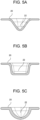
- FIGS. 5A, 5B, and 5C provide exemplary sectional shapes of protrusion 22, illustrating a substantially triangular section, a quadrangular section, and a substantially semicircular section, respectively.
- Each of these concave shapes allows for securement of an exhaust gas flow passage when its bottom is pressed against the face of holder 12.
- a face of duct cover 20 that is opposite a face with the protrusions is sunken where the protrusions are formed.
- the protrusions may be solid protrusions where the face is not sunken.
- FIG. 6 is a plan view of duct cover 20, illustrating an example where essentially six protrusions 22 are arranged around one through hole 18 in end face 13. While respective end sides of a front-end and a rear-end row of cells 14 have no arrangement of protrusions 22 in this example, protrusions 22 may also be arranged on these end sides.
- FIG. 7 is a plan view of duct cover 20, illustrating an example where essentially three protrusions 22 are arranged above and around one cell 14.
- protrusions 22 may also be arranged on respective end sides of a front-end and a rear-end row of cells 14.
- duct cover 20 having such a configuration as illustrated in each of FIGS. 6 and 7 is pressed against holder 12, duct cover 20 can secure an exhaust gas flow passage around protrusions 22 because protrusions 22 abut the face of holder 12.
Landscapes
- Chemical & Material Sciences (AREA)
- Chemical Kinetics & Catalysis (AREA)
- Electrochemistry (AREA)
- General Chemical & Material Sciences (AREA)
- Engineering & Computer Science (AREA)
- Power Engineering (AREA)
- Microelectronics & Electronic Packaging (AREA)
- Inorganic Chemistry (AREA)
- Battery Mounting, Suspending (AREA)
- Gas Exhaust Devices For Batteries (AREA)
Abstract
Description
- The present disclosure relates to a power storage module.
- For power storage devices such as lithium-ion cells, various factors, including overcharging and overcurrent, can contribute to gas generation inside the power storage device and an increase in internal pressure. A power storage device is prepared for such a situation by including an exhaust valve. When the internal pressure of the power storage device increases, the exhaust valve opens and releases gas, thus preventing the internal pressure of the power storage device from rising above a predetermined level.
- Since voltage and cell capacity of the single power storage device are relatively low, plural battery cells are used to obtain a specified capacity and a specified output voltage by being connected in parallel and series. In that case, the specified number of power storage devices are often housed in a case to form a power storage module. The power storage module can have, inside the case, a passage for the gas released from each of the power storage devices. This passage for exhaust gas flow inside the case may be blocked, particularly when there is an external impact.
- A battery pack described in
PTL 1 uses plural secondary cells, which are exemplary power storage devices, and includes an exhaust duct and an exhaust port for emitting the gas released from the plural power storage devices, with a noise reduction part provided at the exhaust port. - PTL 1:
Japanese Patent Application Laid-open No. 2011-204574 - However, when the exhaust duct described in
PTL 1 collapses due to an external impact on power storage modules, the exhaust valves of the power storage devices may be obstructed, for example, by an upper cover of the exhaust duct. The power storage devices obstructed by the upper cover or the like cannot perform sufficient gas release and can make it difficult for their internal pressure to increase. - A power storage module according to the present disclosure includes a holder that includes a plurality of housing parts housing a plurality of power storage devices, each with an exhaust valve, and a plurality of through holes connecting the plurality of housing parts and an outside; and a duct cover covering an end face of the holder where the exhaust valves of the plurality of power storage devices are exposed through the plurality of through holes and forming a gas flow passage with the end face. The duct cover includes a plurality of protrusions discretely protruding toward the end face. The plurality of protrusions include respective leading ends facing a remaining part of the end face where the plurality of through holes are absent.
- The power storage module according to the present disclosure has improved reliability.
-
-
FIG. 1 is an external perspective view schematically illustrating a configuration ofbattery module 10. -
FIG. 2 is a perspective view illustratingbattery module 10, withduct cover 20 removed. -
FIG. 3 is adiagram illustrating protrusions 22 ofduct cover 20 that are engaged in recesses ofperipheral wall 16. -
FIG. 4A is a diagram for showing howbattery module 10 experiences a load applied from above, illustrating a state before the load application. -
FIG. 4B is a diagram for showing howbattery module 10 experiences the load applied from above, illustrating a state after the load application. -
FIG. 5A is a diagram illustrating an exemplary sectional shape ofprotrusion 22, in which case the shape is triangular. -
FIG. 5B is a diagram illustrating an exemplary sectional shape ofprotrusion 22, in which case the shape is quadrangular. -
FIG. 5C is a diagram illustrating an exemplary sectional shape ofprotrusion 22, in which case the shape is semicircular. -
FIG. 6 is a diagram illustrating an exemplary arrangement ofprotrusions 22 ofduct cover 20. -
FIG. 7 is a diagram illustrating another exemplary arrangement ofprotrusions 22 ofduct cover 20. - With reference to the drawings, a detailed description is hereinafter provided of an exemplary embodiment of a battery module that uses cylindrical cells, and which is given as an example of a power storage module according to the present disclosure. It is to be noted that the present disclosure encompasses configurations obtained by selectively combining the exemplary embodiment and plural modifications that are to be described below. Furthermore, power storage devices to be used in the power storage module according to the present disclosure are not limited to cylindrical cells and may be capacitors.
-
FIG. 1 is an external perspective view schematically illustrating a configuration ofbattery module 10, while inFIG. 2 ,duct cover 20 is removed. -
Holder 12 is generally a rectangular parallelepiped, housingplural cells 14.Holder 12 includes plural vertically and cylindricallybored housing parts 15 wherecells 14 are housed, respectively.Holder 12 includes plural throughholes 17 formed inend face 13. These throughholes 17 allow communication between an outside ofholder 12 andcorresponding housing parts 15 and are wherecells 14 are exposed. In this example, eachcell 14 is cylindrical but is not limited to the cylindrical shape. Eachcell 14 may be, for example, prismatic. For example, eachcell 14 may include an electrode body including a positive electrode and a negative electrode; an outer covering can housing the electrode body and an electrolyte; and a sealing plate closing an opening of the outer covering can via a gasket. The sealing plate is electrically connected to one of the positive and negative electrodes via a lead, and the outer covering can is electrically connected to the other of the positive and negative electrodes. The plural cells may be arranged, for example, in a staggered configuration where the cells are arranged in plural rows in a front-to-rear direction and are out of alignment in columns adjacent in a left-to-right direction. -
Holder 12 includes upward projectingperipheral wall 16 along a peripheral edge (periphery) ofend face 13, and this disposedperipheral wall 16 surroundsinternal space 18. Disposed on an upper side ofperipheral wall 16 isduct cover 20 serving as a lid forinternal space 18 to be maintained above end face 13 (the upper face) ofholder 12.Internal space 18 functions as a flow passage (described later) for exhaust gas fromcells 14. -
Plural cells 14 are electrically connected in parallel and series as appropriate. Therefore, although not illustrated, bus bars or the likes are provided ininternal space 18, connectingcells 14.Holder 12 can be made of synthetic resin, andduct cover 20 can be made of metal, such as aluminum or aluminum alloy, or synthetic resin treated to withstand gas temperature and possess more strength than the material forholder 12. - Duct
cover 20 herein includes plural discretely arrangedprotrusions 22 bulging downward (toward end face 13). In the example ofFIG. 1 ,duct cover 20 hasplural protrusions 22 throughout, including at ends in the left-to-right direction.Peripheral wall 16, which extends upward from the periphery ofholder 12, includes on a left and aright side recesses 24 corresponding in shape toterminal protrusions 22a ofduct cover 20, allowingterminal protrusions 22a to engage in and be housed. While each ofterminal protrusions 22a is shaped by cutting away roughly half ofprotrusion 22 in this example, eachterminal protrusion 22a does not necessarily have to be half and may be larger or smaller in size thanprotrusion 22. However,terminal protrusions 22a andprotrusions 22 are preferably formed using the same process. Any number ofterminal protrusions 22a can be provided anywhere and may correspond to rows ofprotrusions 22. Various forming processes can be used to formsuch protrusions 22 andterminal protrusions 22a. -
FIG. 3 is a diagram illustratingduct cover 20 being supported byperipheral wall 16, withprotrusions 22 ofduct cover 20 engaged inrecesses 24 ofperipheral wall 16. This engagement ofprotrusions 22 ofduct cover 20 inrecesses 24 allows for positioning ofduct cover 20 in the front-to-rear direction with respect toperipheral wall 16. - In
FIGS. 1 and3 , side faces ofduct cover 20 are gray-colored for convenience's sake. - In this configuration,
internal space 18 is maintained abovecells 14.Peripheral wall 16 partly includesexhaust port 32. Using thisexhaust port 32 as an exhaust outlet,internal space 18 functions as the exhaust gas flow passage.Peripheral wall 16 may haveexhaust port 32 anywhere (in any one of four sides ifperipheral wall 16 is quadrangular).Peripheral wall 16 may haveplural exhaust ports 32, instead of oneexhaust port 32.Exhaust port 32 should be appropriately located, depending on wherebattery module 10 is disposed. Vertical Impact -
FIGS. 5A and 5B illustrate how duct cover 20 is pressed against the face ofholder 12 due to a load applied tobattery module 10 from above. Under normal conditions,duct cover 20 is supported byperipheral wall 16 and thus is positioned aboveholder 12, keepinginternal space 18, as illustrated inFIG. 5A . - When a front-to-rear impact (the load from above) acts,
metal duct cover 20, which is stronger than resin-madeperipheral wall 16, destroysperipheral wall 16 and is pressed against the upper face ofholder 12, as illustrated inFIG. 5B . - In the example given here,
protrusions 22 ofduct cover 20 are vertically out of alignment withcells 14, being positioned to correspond to the upper face (end face 13) ofholder 12. Therefore, when duct cover 20 is pressed againstholder 12,protrusions 22 are pressed against an area of end face 13 among throughholes 18 at their respective lower ends (leading ends). As a result,exhaust space 40 is formed amongprotrusions 22, being secured abovecells 14. - Around each
cell 14,duct cover 20 should haveplural protrusions 22, preferably three or more. -
Exhaust valve 42 is disposed at an upper end of eachcell 14. Thisexhaust valve 42 is a valve that releases the internal gas when internal pressure ofcell 14 increases. Forexhaust valve 42, various configurations that are conventionally known can be adopted. For example,exhaust valve 42 may be such that a sealing plate partly includes a weak part that breaks when the internal pressure ofcell 14 exceeds a predetermined value. Another alternative is thatexhaust valve 42 may be of a self-reset type that reseals the cell after releasing the gas. Eachcell 14 may include an exhaust section at a bottom of the outer covering can. The gas released fromexhaust valve 42 is emitted out ofbattery module 10 throughexhaust space 40 andexhaust port 32. - Even when
protrusions 22 are in contact with the upper face ofholder 12, discretely arrangedprotrusions 22 ensure thatexhaust space 40 surroundsprotrusions 22, enabling the exhaust gas to be emitted fromexhaust port 32. The vacant space betweenadjacent protrusions 22 communicates with exhaust port 32 (the exhaust outlet) onend face 13 in a direction parallel to endface 13. The phrase "communicates with exhaust port 32 (the exhaust outlet) onend face 13" herein means communication withexhaust port 32 without using the original exhaust passage between the leading ends ofprotrusions 22 andend face 13. There may be protrusion(s) 22 disposed to face the exhaust port in a protruding direction of protrusion(s) 22. By facingexhaust port 32, protrusion(s) 22 can come into contact with an exhaust port-side area ofend face 13. The configuration using this (these) protrusion(s) 22 enables prevention of blockage ofexhaust port 32 when duct cover 20 is pressed againstend face 13.Exhaust port 32 to be formed inperipheral wall 16 may be a cutout extending downward from an upper edge ofperipheral wall 16. This configuration facilitates the emission of air betweenadjacent protrusions 22 throughexhaust port 32 in a state beforeduct cover 20 is pressed against end face 13 ofholder 12, compared to whenexhaust part 32 is defined within an annular frame. -
Holder 12 in the drawings is solid and resin-made and has vertically boredhousing parts 15 forcells 14; however, various configurations can be adopted forholder 12 as long ascells 14 can be held. - While
duct cover 20 has been described as being aboveholder 12, its position may be vertically reversed, in whichcase duct cover 20 is underholder 12, andexhaust space 40 is also formed at a lower side ofholder 12. -
FIGS. 5A, 5B, and 5C provide exemplary sectional shapes ofprotrusion 22, illustrating a substantially triangular section, a quadrangular section, and a substantially semicircular section, respectively. - Each of these concave shapes allows for securement of an exhaust gas flow passage when its bottom is pressed against the face of
holder 12. A face ofduct cover 20 that is opposite a face with the protrusions is sunken where the protrusions are formed. However, the protrusions may be solid protrusions where the face is not sunken. -
FIG. 6 is a plan view ofduct cover 20, illustrating an example where essentially sixprotrusions 22 are arranged around one throughhole 18 inend face 13. While respective end sides of a front-end and a rear-end row ofcells 14 have no arrangement ofprotrusions 22 in this example,protrusions 22 may also be arranged on these end sides. -
FIG. 7 is a plan view ofduct cover 20, illustrating an example where essentially threeprotrusions 22 are arranged above and around onecell 14. In this example as well,protrusions 22 may also be arranged on respective end sides of a front-end and a rear-end row ofcells 14. - Even when duct cover 20 having such a configuration as illustrated in each of
FIGS. 6 and7 is pressed againstholder 12,duct cover 20 can secure an exhaust gas flow passage aroundprotrusions 22 becauseprotrusions 22 abut the face ofholder 12. -
- 10: battery module (power storage module)
- 12: holder
- 13: end face
- 14: cell (power storage device)
- 15: housing part
- 16: peripheral wall
- 17: through hole
- 18: internal space
- 20: duct cover
- 22: protrusion
- 22a: terminal protrusion
- 24: recess
- 32: exhaust port
- 40: exhaust space
- 42: exhaust valve
Claims (6)
- A power storage module comprising:a holder includinga plurality of housing parts housing a plurality of power storage devices that each include an exhaust valve anda plurality of through holes connecting the plurality of housing parts and an outside; anda duct cover covering an end face of the holder where exhaust valves of the plurality of power storage devices are exposed through the plurality of through holes and defining a gas flow passage with the end face, whereinthe duct cover includes a plurality of protrusions discretely protruding toward the end face, andthe plurality of protrusions include respective leading ends facing a remaining part of the end face where the plurality of through holes are absent.
- The power storage module according to claim 1, whereinthe holder includes along a periphery of the holder a peripheral wall projecting from the end face, andthe peripheral wall includes at least one recess allowing the plurality of protrusions to engage in and be housed.
- The power storage module according to claim 1 or 2, wherein the plurality of protrusions arrange the plurality of through holes in the holder around the plurality of protrusions.
- The power storage module according to any one of claims 1 to 4, further comprising an exhaust outlet, wherein
a vacant space among the plurality of protrusions communicates with the exhaust outlet on the end face in a direction parallel to the end face. - The power storage module according to any one of claims 1 to 4, further comprising an exhaust outlet, wherein
at least one of the plurality of protrusions faces the exhaust outlet in a protruding direction of the at least one of the plurality of protrusions. - The power storage module according to claim 5, whereinthe holder includes along a periphery of the holder a peripheral wall projecting from the end face, andthe exhaust outlet is formed by cutting out in a peripheral wall.
Applications Claiming Priority (2)
| Application Number | Priority Date | Filing Date | Title |
|---|---|---|---|
| JP2022029789 | 2022-02-28 | ||
| PCT/JP2023/005911 WO2023162910A1 (en) | 2022-02-28 | 2023-02-20 | Electric power storage module |
Publications (2)
| Publication Number | Publication Date |
|---|---|
| EP4489204A1 true EP4489204A1 (en) | 2025-01-08 |
| EP4489204A4 EP4489204A4 (en) | 2025-07-30 |
Family
ID=87765760
Family Applications (1)
| Application Number | Title | Priority Date | Filing Date |
|---|---|---|---|
| EP23759911.3A Pending EP4489204A4 (en) | 2022-02-28 | 2023-02-20 | ELECTRICAL POWER STORAGE MODULE |
Country Status (5)
| Country | Link |
|---|---|
| US (1) | US20250149709A1 (en) |
| EP (1) | EP4489204A4 (en) |
| JP (1) | JPWO2023162910A1 (en) |
| CN (1) | CN118749162A (en) |
| WO (1) | WO2023162910A1 (en) |
Families Citing this family (1)
| Publication number | Priority date | Publication date | Assignee | Title |
|---|---|---|---|---|
| TWI901232B (en) * | 2024-06-26 | 2025-10-11 | 嘉盈鋰源股份有限公司 | Battery module and battery box thereof |
Family Cites Families (6)
| Publication number | Priority date | Publication date | Assignee | Title |
|---|---|---|---|---|
| JP4749513B2 (en) * | 2009-07-17 | 2011-08-17 | パナソニック株式会社 | Battery module and battery pack using the same |
| JP5466906B2 (en) * | 2009-09-18 | 2014-04-09 | パナソニック株式会社 | Battery module |
| JP2011204574A (en) | 2010-03-26 | 2011-10-13 | Panasonic Corp | Battery pack |
| CN102696132A (en) * | 2010-07-29 | 2012-09-26 | 松下电器产业株式会社 | Battery module |
| WO2020188949A1 (en) * | 2019-03-19 | 2020-09-24 | 三洋電機株式会社 | Battery module |
| CN114270609A (en) * | 2019-08-07 | 2022-04-01 | 三洋电机株式会社 | Power supply device, and electrically powered vehicle and power storage device using same |
-
2023
- 2023-02-20 CN CN202380023253.8A patent/CN118749162A/en active Pending
- 2023-02-20 EP EP23759911.3A patent/EP4489204A4/en active Pending
- 2023-02-20 JP JP2024503127A patent/JPWO2023162910A1/ja active Pending
- 2023-02-20 WO PCT/JP2023/005911 patent/WO2023162910A1/en not_active Ceased
- 2023-02-20 US US18/839,754 patent/US20250149709A1/en active Pending
Also Published As
| Publication number | Publication date |
|---|---|
| WO2023162910A1 (en) | 2023-08-31 |
| JPWO2023162910A1 (en) | 2023-08-31 |
| US20250149709A1 (en) | 2025-05-08 |
| CN118749162A (en) | 2024-10-08 |
| EP4489204A4 (en) | 2025-07-30 |
Similar Documents
| Publication | Publication Date | Title |
|---|---|---|
| EP3916866B1 (en) | Battery pack | |
| EP3125334B1 (en) | Energy storage apparatus | |
| US9231237B2 (en) | Cell module | |
| EP3043401B1 (en) | Battery module | |
| CN114223091B (en) | Battery Pack | |
| KR102243578B1 (en) | Secondary Battery Pack | |
| KR101136320B1 (en) | Battery, vehicle, and equipment using battery | |
| CN101164182B (en) | Secondary battery | |
| KR20160112768A (en) | Battery pack for a vehicle | |
| CN103579544A (en) | Motor vehicle battery | |
| EP4489204A1 (en) | Electric power storage module | |
| JP4283951B2 (en) | Sealed prismatic battery | |
| EP4395040A1 (en) | Battery pack and vehicle including same | |
| JP7172484B2 (en) | battery module | |
| KR102926474B1 (en) | Battery pack and vehicle including same | |
| US20250174817A1 (en) | Power storage module | |
| CN111164792A (en) | Electricity storage device | |
| JP7067301B2 (en) | Battery module and battery module manufacturing method | |
| EP4411957B1 (en) | Battery pack | |
| JP7731928B2 (en) | Battery pack | |
| EP4567995A1 (en) | Battery pack and vehicle including same | |
| US20250174794A1 (en) | Battery pack | |
| CN223651569U (en) | Battery pack | |
| US20260074365A1 (en) | Power storage module | |
| EP4704237A1 (en) | Power supply equipment |
Legal Events
| Date | Code | Title | Description |
|---|---|---|---|
| STAA | Information on the status of an ep patent application or granted ep patent |
Free format text: STATUS: THE INTERNATIONAL PUBLICATION HAS BEEN MADE |
|
| PUAI | Public reference made under article 153(3) epc to a published international application that has entered the european phase |
Free format text: ORIGINAL CODE: 0009012 |
|
| STAA | Information on the status of an ep patent application or granted ep patent |
Free format text: STATUS: REQUEST FOR EXAMINATION WAS MADE |
|
| 17P | Request for examination filed |
Effective date: 20240912 |
|
| AK | Designated contracting states |
Kind code of ref document: A1 Designated state(s): AL AT BE BG CH CY CZ DE DK EE ES FI FR GB GR HR HU IE IS IT LI LT LU LV MC ME MK MT NL NO PL PT RO RS SE SI SK SM TR |
|
| DAV | Request for validation of the european patent (deleted) | ||
| DAX | Request for extension of the european patent (deleted) | ||
| A4 | Supplementary search report drawn up and despatched |
Effective date: 20250702 |
|
| RIC1 | Information provided on ipc code assigned before grant |
Ipc: H01M 50/367 20210101AFI20250626BHEP Ipc: H01G 11/10 20130101ALI20250626BHEP Ipc: H01G 11/78 20130101ALI20250626BHEP Ipc: H01M 50/209 20210101ALI20250626BHEP Ipc: H01M 50/213 20210101ALI20250626BHEP Ipc: H01M 50/342 20210101ALI20250626BHEP Ipc: H01M 50/35 20210101ALI20250626BHEP Ipc: H01G 11/18 20130101ALI20250626BHEP Ipc: H01G 11/82 20130101ALI20250626BHEP Ipc: H01M 50/204 20210101ALI20250626BHEP Ipc: H01M 50/289 20210101ALI20250626BHEP Ipc: H01M 50/271 20210101ALI20250626BHEP Ipc: H01M 50/30 20210101ALI20250626BHEP Ipc: H01M 50/358 20210101ALI20250626BHEP |