EP4489145A1 - Current collector disc and battery - Google Patents
Current collector disc and battery Download PDFInfo
- Publication number
- EP4489145A1 EP4489145A1 EP23851767.6A EP23851767A EP4489145A1 EP 4489145 A1 EP4489145 A1 EP 4489145A1 EP 23851767 A EP23851767 A EP 23851767A EP 4489145 A1 EP4489145 A1 EP 4489145A1
- Authority
- EP
- European Patent Office
- Prior art keywords
- grooves
- holes
- current collector
- disk
- infiltration
- Prior art date
- Legal status (The legal status is an assumption and is not a legal conclusion. Google has not performed a legal analysis and makes no representation as to the accuracy of the status listed.)
- Pending
Links
Images
Classifications
-
- H—ELECTRICITY
- H01—ELECTRIC ELEMENTS
- H01M—PROCESSES OR MEANS, e.g. BATTERIES, FOR THE DIRECT CONVERSION OF CHEMICAL ENERGY INTO ELECTRICAL ENERGY
- H01M10/00—Secondary cells; Manufacture thereof
- H01M10/05—Accumulators with non-aqueous electrolyte
- H01M10/052—Li-accumulators
- H01M10/0525—Rocking-chair batteries, i.e. batteries with lithium insertion or intercalation in both electrodes; Lithium-ion batteries
-
- H—ELECTRICITY
- H01—ELECTRIC ELEMENTS
- H01M—PROCESSES OR MEANS, e.g. BATTERIES, FOR THE DIRECT CONVERSION OF CHEMICAL ENERGY INTO ELECTRICAL ENERGY
- H01M50/00—Constructional details or processes of manufacture of the non-active parts of electrochemical cells other than fuel cells, e.g. hybrid cells
- H01M50/30—Arrangements for facilitating escape of gases
- H01M50/342—Non-re-sealable arrangements
- H01M50/3425—Non-re-sealable arrangements in the form of rupturable membranes or weakened parts, e.g. pierced with the aid of a sharp member
-
- H—ELECTRICITY
- H01—ELECTRIC ELEMENTS
- H01M—PROCESSES OR MEANS, e.g. BATTERIES, FOR THE DIRECT CONVERSION OF CHEMICAL ENERGY INTO ELECTRICAL ENERGY
- H01M50/00—Constructional details or processes of manufacture of the non-active parts of electrochemical cells other than fuel cells, e.g. hybrid cells
- H01M50/10—Primary casings; Jackets or wrappings
- H01M50/102—Primary casings; Jackets or wrappings characterised by their shape or physical structure
- H01M50/107—Primary casings; Jackets or wrappings characterised by their shape or physical structure having curved cross-section, e.g. round or elliptic
-
- H—ELECTRICITY
- H01—ELECTRIC ELEMENTS
- H01M—PROCESSES OR MEANS, e.g. BATTERIES, FOR THE DIRECT CONVERSION OF CHEMICAL ENERGY INTO ELECTRICAL ENERGY
- H01M50/00—Constructional details or processes of manufacture of the non-active parts of electrochemical cells other than fuel cells, e.g. hybrid cells
- H01M50/10—Primary casings; Jackets or wrappings
- H01M50/147—Lids or covers
- H01M50/148—Lids or covers characterised by their shape
- H01M50/152—Lids or covers characterised by their shape for cells having curved cross-section, e.g. round or elliptic
-
- H—ELECTRICITY
- H01—ELECTRIC ELEMENTS
- H01M—PROCESSES OR MEANS, e.g. BATTERIES, FOR THE DIRECT CONVERSION OF CHEMICAL ENERGY INTO ELECTRICAL ENERGY
- H01M50/00—Constructional details or processes of manufacture of the non-active parts of electrochemical cells other than fuel cells, e.g. hybrid cells
- H01M50/30—Arrangements for facilitating escape of gases
-
- H—ELECTRICITY
- H01—ELECTRIC ELEMENTS
- H01M—PROCESSES OR MEANS, e.g. BATTERIES, FOR THE DIRECT CONVERSION OF CHEMICAL ENERGY INTO ELECTRICAL ENERGY
- H01M50/00—Constructional details or processes of manufacture of the non-active parts of electrochemical cells other than fuel cells, e.g. hybrid cells
- H01M50/50—Current conducting connections for cells or batteries
- H01M50/531—Electrode connections inside a battery casing
- H01M50/533—Electrode connections inside a battery casing characterised by the shape of the leads or tabs
-
- H—ELECTRICITY
- H01—ELECTRIC ELEMENTS
- H01M—PROCESSES OR MEANS, e.g. BATTERIES, FOR THE DIRECT CONVERSION OF CHEMICAL ENERGY INTO ELECTRICAL ENERGY
- H01M50/00—Constructional details or processes of manufacture of the non-active parts of electrochemical cells other than fuel cells, e.g. hybrid cells
- H01M50/50—Current conducting connections for cells or batteries
- H01M50/531—Electrode connections inside a battery casing
- H01M50/538—Connection of several leads or tabs of wound or folded electrode stacks
-
- H—ELECTRICITY
- H01—ELECTRIC ELEMENTS
- H01M—PROCESSES OR MEANS, e.g. BATTERIES, FOR THE DIRECT CONVERSION OF CHEMICAL ENERGY INTO ELECTRICAL ENERGY
- H01M50/00—Constructional details or processes of manufacture of the non-active parts of electrochemical cells other than fuel cells, e.g. hybrid cells
- H01M50/50—Current conducting connections for cells or batteries
- H01M50/543—Terminals
- H01M50/552—Terminals characterised by their shape
- H01M50/559—Terminals adapted for cells having curved cross-section, e.g. round, elliptic or button cells
-
- H—ELECTRICITY
- H01—ELECTRIC ELEMENTS
- H01M—PROCESSES OR MEANS, e.g. BATTERIES, FOR THE DIRECT CONVERSION OF CHEMICAL ENERGY INTO ELECTRICAL ENERGY
- H01M50/00—Constructional details or processes of manufacture of the non-active parts of electrochemical cells other than fuel cells, e.g. hybrid cells
- H01M50/60—Arrangements or processes for filling or topping-up with liquids; Arrangements or processes for draining liquids from casings
- H01M50/609—Arrangements or processes for filling with liquid, e.g. electrolytes
-
- H—ELECTRICITY
- H01—ELECTRIC ELEMENTS
- H01M—PROCESSES OR MEANS, e.g. BATTERIES, FOR THE DIRECT CONVERSION OF CHEMICAL ENERGY INTO ELECTRICAL ENERGY
- H01M50/00—Constructional details or processes of manufacture of the non-active parts of electrochemical cells other than fuel cells, e.g. hybrid cells
- H01M50/60—Arrangements or processes for filling or topping-up with liquids; Arrangements or processes for draining liquids from casings
- H01M50/609—Arrangements or processes for filling with liquid, e.g. electrolytes
- H01M50/627—Filling ports
-
- H—ELECTRICITY
- H01—ELECTRIC ELEMENTS
- H01M—PROCESSES OR MEANS, e.g. BATTERIES, FOR THE DIRECT CONVERSION OF CHEMICAL ENERGY INTO ELECTRICAL ENERGY
- H01M2200/00—Safety devices for primary or secondary batteries
- H01M2200/20—Pressure-sensitive devices
-
- Y—GENERAL TAGGING OF NEW TECHNOLOGICAL DEVELOPMENTS; GENERAL TAGGING OF CROSS-SECTIONAL TECHNOLOGIES SPANNING OVER SEVERAL SECTIONS OF THE IPC; TECHNICAL SUBJECTS COVERED BY FORMER USPC CROSS-REFERENCE ART COLLECTIONS [XRACs] AND DIGESTS
- Y02—TECHNOLOGIES OR APPLICATIONS FOR MITIGATION OR ADAPTATION AGAINST CLIMATE CHANGE
- Y02E—REDUCTION OF GREENHOUSE GAS [GHG] EMISSIONS, RELATED TO ENERGY GENERATION, TRANSMISSION OR DISTRIBUTION
- Y02E60/00—Enabling technologies; Technologies with a potential or indirect contribution to GHG emissions mitigation
- Y02E60/10—Energy storage using batteries
Definitions
- the present disclosure relates to the field of lithium batteries, for example, to a current collector disk, and a battery including the current collector disk.
- a current collector disk serves to collect currents. It has been found that the structure design of the current collector disk is strongly related to safety of a cell, and the related art employs an integrated welding of the current collector disk to a surface of a pole piece of the cell. Under a condition that the cell undergoes thermal runaway, the current collector disk is disk deformed with the cell and becomes stuck at a pressure-relief opening, preventing active materials and gases inside the cell from being released in a timely manner, thereby causing the battery to experience thermal runaway, leading to safety issues such as fire and explosion.
- the present disclosure provides a current collector disk that enables the cell to release pressure in a timely manner.
- the present disclosure provides a battery having a good quality and a high safety factor.
- an embodiment of the present disclosure provides a current collector disk including a disk body on which a plurality of infiltration holes is provided, the plurality of infiltration holes extending through the disk body in a direction of a thickness of the disk body, the disk body having a first side surface and a second side surface disposed oppositely, the first side surface being recessed with a plurality of grooves, at least one end of each of the plurality of grooves communicating with a respective one of the plurality of infiltration holes.
- an embodiment of the present disclosure provides a battery including the current collector disk as described above.
- the beneficial effects of the present disclosure are as follows.
- the current collector disk of the present disclosure is provided with grooves. Under a condition that the cell experiences a safety failure, excessive gas production or expansion within the cell occurs, the disk body is squeezed and deformed. Due to the lower strength of the grooves, a portion of the disk body corresponding to the bottom of the grooves is prone to rupture, which may provide space for the cell expansion.
- the infiltration holes are hole structures provided on the disk body. Under a condition that the disk body is subjected to external forces, the periphery of the infiltration holes is prone to stress concentration. Connecting the grooves with the infiltration holes allows the grooves to be located in areas of the disk body where stress concentration occurs. Under a condition that the cell expands, the portion of the disk body corresponding to the bottom of the grooves may be quickly torn, ensuring that the internal pressure of the battery may be released in a timely manner.
- a current collector disk includes a disk body 1 on which a plurality of infiltration holes 2 is provided for accelerating the infiltration of active substances by electrolytes.
- the plurality of infiltration holes 2 extend through the disk body 1 in a direction of a thickness of the disk body 1.
- the disk body 1 has a first side surface 11 and a second side surface 12 which are oppositely disposed.
- the first side surface 11 is recessed with a plurality of grooves 3. At least one end of each of the plurality of grooves 3 communicates with a respective one of the plurality of infiltration holes 2.
- the cell expands towards a direction of a pressure-relief channel, causing the disk body 1 to be squeezed and deformed.
- a portion of the disk body 1 corresponding to the bottom of the grooves 3 is prone to rupture, which may provide space for the cell expansion.
- the current collector disk is deformed along with the cell, effectively alleviating the issue of the current collector disk blocking the pressure-relief channel.
- the infiltration holes 2 are hole structures provided on the disk body 1. Under a condition that the disk body 1 is subjected to external forces, the periphery of the infiltration holes 2 is prone to stress concentration.
- the grooves 3 Connecting the grooves 3 with the infiltration holes 2 allows the grooves 3 to be located in areas of the disk body 1 where stress concentration occurs. Under a condition that the cell is deformed, the portion of the disk body 1 corresponding to the bottom of the grooves 3 may be quickly torn, ensuring that the internal pressure of a battery may be released in a timely manner.
- the infiltration holes 2 include a first hole 21 and a plurality of second holes 22.
- the first hole 21 is located at a center of the disk body 1.
- the plurality of second holes 22 are arranged at intervals in a circumferential direction of the first hole 21.
- the grooves 3 includes a plurality of first groove 31, one end of each of the plurality of first grooves 31 communicating with the first hole 21 and another end of the first groove 31 communicating with a respective one of the plurality of second holes 22.
- the second holes 22 are evenly arranged in the circumferential direction of the first holes 21, so that the electrolytes may evenly flow into an inside of the cell, a contact area between the electrolytes and the cell is ensured, and an infiltration efficiency of the electrolytes is improved.
- the disk body 1 By configuring the two ends of each of the first grooves 31 to be connected to the first hole 21 and the second hole 22 respectively, the disk body 1 has a weakened area extending from the center to an edge, ensuring that under a condition that the cell is deformed, the portion of the disk body 1 corresponding to the bottom of the grooves 3 may be torn.
- the number of grooves 3 may be adjusted according to the number of second holes 22 as needed.
- the second holes 22 are provided with four.
- the first grooves 31 are provided with four.
- the first grooves 31 are each bar-shaped, and the four first grooves 31 are arranged in a "cross" shape.
- ends of the first grooves 31 adjacent to the first hole 21 are first torn, and cracks may be gradually extended along lengthwise directions of the first grooves 31 in straight lines, which may ensure that the weakened area of the current collector disk is torn in a timely manner, and the internal pressure may be effectively released.
- the current collector disk is a negative current collector disk
- the disk body 1 is made of metal.
- the grooves 3 further includes a plurality of second grooves 32, and two adjacent ones of the plurality of second holes 22 communicate through a respective one of the plurality of second grooves 32. Under a condition that the cell is deformed, an area of a middle portion of the disk body 1 is flanged with an outward movement of the cell, so that the middle portion of the disk body 1 may form the pressure-relief channel to provide space for the expansion of the cell.
- the second grooves 32 are provided, so that the middle portion of the disk body 1 may be flanged more easily.
- the area of the middle portion of the disk body 1 may be flanged, presenting a "blossoming" phenomenon, which enables the pressure to be released in a timely manner.
- the number of the second holes 22 is not limited to four. In one embodiment, the number of the second holes 22 is from three to six in order to ensure an electrolyte injection rate.
- the second grooves 32 are each arcuate. By providing the arcuate second grooves 32, the second grooves 32 each protrude toward one side away from the center of the disk body 1, and during processing, a tool similar to a compass pattern may be used for scribing, with one end of the tool being fixed, and another end of the tool being rotated around the fixed end for scribing.
- the second grooves 32 may each have other shapes, for example, a linear shape, a corrugated shape, a broken line shape, and the like.
- the second grooves 32 may have indefinite shapes, and it is only necessary to ensure that the second grooves 32 communicates with the second holes 22.
- the arcuate second grooves 32 in the present embodiment is a preferred structure.
- the first grooves 31 and the second grooves 32 are each provided with four, and all the second grooves 32 enclose a circle.
- the second grooves 32 are not limited to an arcuate shape, but may each have a linear shape, a broken line shape, a corrugated shape, and the like.
- the grooves 3 are provided on the first side face 11 of the disk body 1.
- the thickness of the disk body 1 is H1
- a distance between a bottom of the grooves 3 and the second side face 12 of the disk body 1 is H2
- 0.2 ⁇ H2/H1 ⁇ 0.8 By defining a thickness of H2, it is possible to avoid that a local thickness of the current collector disk is too small, to ensure the strength of the current collector disk, and to avoid that the local thickness of the current collector disk is too thin to cause breakage of the current collector disk during installation.
- depths of the first grooves 31 and the second grooves 32 may be the same or different, and it is only necessary to ensure that the depths of the first grooves 31 and the second grooves 32 are in respective ranges.
- an edge of the disk body 1 is recessed with infiltration notches 4.
- the electrolytes may flow to the cell along an inner wall of a housing, thereby increasing an infiltration rate of the electrolytes.
- the infiltration notches 4 are arcuate.
- a diameter of each of the infiltration notches 4 is D1.
- the first holes 21 and the second holes 22 are circular holes.
- a diameter of each of the first holes 21 and the second holes 22 are D2 and D1>D2. Because the edge of the current collector disk is connected to the housing, a larger diameter is required for the liquid injection provided at the edge of the current collector disk, so that a cross-sectional dimension of the infiltration notches 4 may be ensured, and the electrolytes may smoothly flow to the cell.
- each of the second holes 22 is correspondingly provided with one infiltration notch 4.
- the electrolytes are injected into the battery, under a condition that the injection rate of the electrolytes is greater than a flow rate of the electrolytes in the infiltration holes 2, a portion of the electrolytes is accumulated on the current collector disk.
- Correspondingly providing each of the second holes 22 with one infiltration notch 4 allows the electrolytes collected around the second holes 22 to flow to the cell through the infiltration notches 4 in a timely manner, thereby shortening a flow path of the electrolytes and improving the injection efficiency.
- the shapes of the first holes 21 and the second holes 22 are not limited to a circular shape, and the cross-section of the infiltration holes 2 may be circular, square or polygonal.
- the number of the infiltration notches 4 and the number of the infiltration holes 2 are preferably three to six. In the present embodiment, the infiltration notches 4 are provided with five and the infiltration holes 2 are provided with four.
- the present embodiment also provides a battery including a current collector disk in any of the above described embodiments.
- the current collector disk In a normal use state, the current collector disk is not deformed, and therefore the battery using the current collector disk has a good quality.
- the grooves 3 on the current collector disk may be torn by a deformation force of the cell, and the pressure generated by the cell may be released in a timely manner. Therefore, the cell safety factor of the current collector disk is high, and thermal runaway failure is not easy to occur.
Landscapes
- Chemical & Material Sciences (AREA)
- Chemical Kinetics & Catalysis (AREA)
- Electrochemistry (AREA)
- General Chemical & Material Sciences (AREA)
- Engineering & Computer Science (AREA)
- Materials Engineering (AREA)
- Manufacturing & Machinery (AREA)
- Secondary Cells (AREA)
- Connection Of Batteries Or Terminals (AREA)
- Primary Cells (AREA)
Abstract
Description
- The present application claims priority to
Chinese Patent Application No. 202222089899.1 filed with China National Intellectual Property Administration on August 8, 2022 - The present disclosure relates to the field of lithium batteries, for example, to a current collector disk, and a battery including the current collector disk.
- In a cylindrical lithium ion battery, a current collector disk serves to collect currents. It has been found that the structure design of the current collector disk is strongly related to safety of a cell, and the related art employs an integrated welding of the current collector disk to a surface of a pole piece of the cell. Under a condition that the cell undergoes thermal runaway, the current collector disk is disk deformed with the cell and becomes stuck at a pressure-relief opening, preventing active materials and gases inside the cell from being released in a timely manner, thereby causing the battery to experience thermal runaway, leading to safety issues such as fire and explosion.
- The present disclosure provides a current collector disk that enables the cell to release pressure in a timely manner.
- The present disclosure provides a battery having a good quality and a high safety factor.
- In a first aspect, an embodiment of the present disclosure provides a current collector disk including a disk body on which a plurality of infiltration holes is provided, the plurality of infiltration holes extending through the disk body in a direction of a thickness of the disk body, the disk body having a first side surface and a second side surface disposed oppositely, the first side surface being recessed with a plurality of grooves, at least one end of each of the plurality of grooves communicating with a respective one of the plurality of infiltration holes.
- In a second aspect, an embodiment of the present disclosure provides a battery including the current collector disk as described above.
- The beneficial effects of the present disclosure are as follows. The current collector disk of the present disclosure is provided with grooves. Under a condition that the cell experiences a safety failure, excessive gas production or expansion within the cell occurs, the disk body is squeezed and deformed. Due to the lower strength of the grooves, a portion of the disk body corresponding to the bottom of the grooves is prone to rupture, which may provide space for the cell expansion. The infiltration holes are hole structures provided on the disk body. Under a condition that the disk body is subjected to external forces, the periphery of the infiltration holes is prone to stress concentration. Connecting the grooves with the infiltration holes allows the grooves to be located in areas of the disk body where stress concentration occurs. Under a condition that the cell expands, the portion of the disk body corresponding to the bottom of the grooves may be quickly torn, ensuring that the internal pressure of the battery may be released in a timely manner.
- The present disclosure is described in further detail below with reference to the accompanying drawings and embodiments.
-
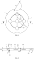
FIG. 1 is a schematic diagram of a current collector disk according to an embodiment of the present disclosure. -
FIG. 2 is a schematic cross-sectional view taken along A-A ofFIG. 1 . - In the drawings:
1. disk body; 11. first side surface; 12. second side surface; 2. infiltration hole; 21. first hole; 22. second hole; 3. groove; 31. first groove; 32. second groove; 4. infiltration notch. - As shown in
FIGS. 1 and 2 , according to the present disclosure, a current collector disk includes adisk body 1 on which a plurality ofinfiltration holes 2 is provided for accelerating the infiltration of active substances by electrolytes. The plurality ofinfiltration holes 2 extend through thedisk body 1 in a direction of a thickness of thedisk body 1. Thedisk body 1 has afirst side surface 11 and asecond side surface 12 which are oppositely disposed. Thefirst side surface 11 is recessed with a plurality of grooves 3. At least one end of each of the plurality of grooves 3 communicates with a respective one of the plurality ofinfiltration holes 2. By providing the groove 3, under a condition that a cell experiences a safety failure, the cell is deformed. The cell expands towards a direction of a pressure-relief channel, causing thedisk body 1 to be squeezed and deformed. At this point, due to the lower strength of the grooves 3, a portion of thedisk body 1 corresponding to the bottom of the grooves 3 is prone to rupture, which may provide space for the cell expansion. The current collector disk is deformed along with the cell, effectively alleviating the issue of the current collector disk blocking the pressure-relief channel. It may be understood that theinfiltration holes 2 are hole structures provided on thedisk body 1. Under a condition that thedisk body 1 is subjected to external forces, the periphery of theinfiltration holes 2 is prone to stress concentration. Connecting the grooves 3 with theinfiltration holes 2 allows the grooves 3 to be located in areas of thedisk body 1 where stress concentration occurs. Under a condition that the cell is deformed, the portion of thedisk body 1 corresponding to the bottom of the grooves 3 may be quickly torn, ensuring that the internal pressure of a battery may be released in a timely manner. - In the present embodiment, the
infiltration holes 2 include afirst hole 21 and a plurality ofsecond holes 22. Thefirst hole 21 is located at a center of thedisk body 1. The plurality ofsecond holes 22 are arranged at intervals in a circumferential direction of thefirst hole 21. The grooves 3 includes a plurality offirst groove 31, one end of each of the plurality offirst grooves 31 communicating with thefirst hole 21 and another end of thefirst groove 31 communicating with a respective one of the plurality ofsecond holes 22. In the present embodiment, thesecond holes 22 are evenly arranged in the circumferential direction of thefirst holes 21, so that the electrolytes may evenly flow into an inside of the cell, a contact area between the electrolytes and the cell is ensured, and an infiltration efficiency of the electrolytes is improved. By configuring the two ends of each of thefirst grooves 31 to be connected to thefirst hole 21 and thesecond hole 22 respectively, thedisk body 1 has a weakened area extending from the center to an edge, ensuring that under a condition that the cell is deformed, the portion of thedisk body 1 corresponding to the bottom of the grooves 3 may be torn. The number of grooves 3 may be adjusted according to the number ofsecond holes 22 as needed. - Referring to
FIG. 1 , thesecond holes 22 are provided with four. Accordingly, thefirst grooves 31 are provided with four. Thefirst grooves 31 are each bar-shaped, and the fourfirst grooves 31 are arranged in a "cross" shape. By providing the bar-shapedfirst grooves 31, under a condition that the cell is deformed, ends of thefirst grooves 31 adjacent to thefirst hole 21 are first torn, and cracks may be gradually extended along lengthwise directions of thefirst grooves 31 in straight lines, which may ensure that the weakened area of the current collector disk is torn in a timely manner, and the internal pressure may be effectively released. - In the present embodiment, the current collector disk is a negative current collector disk, and the
disk body 1 is made of metal. In the present embodiment, the grooves 3 further includes a plurality ofsecond grooves 32, and two adjacent ones of the plurality ofsecond holes 22 communicate through a respective one of the plurality ofsecond grooves 32. Under a condition that the cell is deformed, an area of a middle portion of thedisk body 1 is flanged with an outward movement of the cell, so that the middle portion of thedisk body 1 may form the pressure-relief channel to provide space for the expansion of the cell. Thesecond grooves 32 are provided, so that the middle portion of thedisk body 1 may be flanged more easily. Under a condition that the cell is deformed, the area of the middle portion of thedisk body 1 may be flanged, presenting a "blossoming" phenomenon, which enables the pressure to be released in a timely manner. In other embodiments, the number of thesecond holes 22 is not limited to four. In one embodiment, the number of thesecond holes 22 is from three to six in order to ensure an electrolyte injection rate. - In one embodiment, the
second grooves 32 are each arcuate. By providing the arcuatesecond grooves 32, thesecond grooves 32 each protrude toward one side away from the center of thedisk body 1, and during processing, a tool similar to a compass pattern may be used for scribing, with one end of the tool being fixed, and another end of the tool being rotated around the fixed end for scribing. In other embodiments, thesecond grooves 32 may each have other shapes, for example, a linear shape, a corrugated shape, a broken line shape, and the like. Thesecond grooves 32 may have indefinite shapes, and it is only necessary to ensure that thesecond grooves 32 communicates with the second holes 22. The arcuatesecond grooves 32 in the present embodiment is a preferred structure. - In the present embodiment, at least three grooves 3 are provided. In the present embodiment, the
first grooves 31 and thesecond grooves 32 are each provided with four, and all thesecond grooves 32 enclose a circle. By providing the plurality offirst grooves 31 and the plurality ofsecond grooves 32, under a condition that the cell is deformed, the middle portion of thedisk body 1 is prone to deformation when subjected to pressure, so that the pressure-relief channel is formed in thedisk body 1, and pressure relief is performed in a timely manner. In other embodiments, thesecond grooves 32 are not limited to an arcuate shape, but may each have a linear shape, a broken line shape, a corrugated shape, and the like. - Referring to
FIG. 2 , in the present embodiment, the grooves 3 are provided on thefirst side face 11 of thedisk body 1. The thickness of thedisk body 1 is H1, a distance between a bottom of the grooves 3 and thesecond side face 12 of thedisk body 1 is H2, and 0.2≤H2/H1≤0.8. By defining a thickness of H2, it is possible to avoid that a local thickness of the current collector disk is too small, to ensure the strength of the current collector disk, and to avoid that the local thickness of the current collector disk is too thin to cause breakage of the current collector disk during installation. In the present embodiment, depths of thefirst grooves 31 and thesecond grooves 32 may be the same or different, and it is only necessary to ensure that the depths of thefirst grooves 31 and thesecond grooves 32 are in respective ranges. - Referring to
FIG. 1 , in one embodiment, an edge of thedisk body 1 is recessed withinfiltration notches 4. By providing theinfiltration notches 4, the electrolytes may flow to the cell along an inner wall of a housing, thereby increasing an infiltration rate of the electrolytes. - In the present embodiment, the
infiltration notches 4 are arcuate. A diameter of each of theinfiltration notches 4 is D1. Thefirst holes 21 and thesecond holes 22 are circular holes. A diameter of each of thefirst holes 21 and thesecond holes 22 are D2 and D1>D2. Because the edge of the current collector disk is connected to the housing, a larger diameter is required for the liquid injection provided at the edge of the current collector disk, so that a cross-sectional dimension of theinfiltration notches 4 may be ensured, and the electrolytes may smoothly flow to the cell. - In the present embodiment, each of the
second holes 22 is correspondingly provided with oneinfiltration notch 4. When the electrolytes are injected into the battery, under a condition that the injection rate of the electrolytes is greater than a flow rate of the electrolytes in the infiltration holes 2, a portion of the electrolytes is accumulated on the current collector disk. Correspondingly providing each of thesecond holes 22 with oneinfiltration notch 4 allows the electrolytes collected around thesecond holes 22 to flow to the cell through theinfiltration notches 4 in a timely manner, thereby shortening a flow path of the electrolytes and improving the injection efficiency. - Of course, in other embodiments, the shapes of the
first holes 21 and thesecond holes 22 are not limited to a circular shape, and the cross-section of the infiltration holes 2 may be circular, square or polygonal. The number of theinfiltration notches 4 and the number of the infiltration holes 2 are preferably three to six. In the present embodiment, theinfiltration notches 4 are provided with five and the infiltration holes 2 are provided with four. - The present embodiment also provides a battery including a current collector disk in any of the above described embodiments. In a normal use state, the current collector disk is not deformed, and therefore the battery using the current collector disk has a good quality. Under a condition that the cell is deformed, the grooves 3 on the current collector disk may be torn by a deformation force of the cell, and the pressure generated by the cell may be released in a timely manner. Therefore, the cell safety factor of the current collector disk is high, and thermal runaway failure is not easy to occur.
Claims (10)
- A current collecting disk comprising a disk body on which a plurality of infiltration holes is provided, the plurality of infiltration holes extending through the disk body in a direction of a thickness of the disk body, the disk body having a first side surface and a second side surface which are disposed oppositely, the first side surface being recessed with a plurality of grooves, and at least one end of each of the plurality of grooves communicating with a respective one of the plurality of infiltration holes.
- The current collector disk of claim 1, wherein the plurality of infiltration holes includes a first hole and a plurality of second holes, the first hole being located at a center of the disk body, the plurality of second holes being arranged at intervals in a circumferential direction of the first hole, wherein the grooves include a plurality of first grooves, one end of each of the plurality of first grooves communicating with the first hole and another end of the first groove communicating with a respective one of the plurality of second holes.
- The current collector disk of claim 2, wherein the grooves further include a plurality of second grooves, two adjacent ones of the plurality of second holes communicating through a respective one of the plurality of second grooves.
- The current collector disk of claim 3, wherein the second grooves are each arcuate, the second grooves each protruding toward one side away from the center of the disk body.
- The current collector disk of claim 2, wherein the first grooves are each bar-shaped.
- The current collector disk of claim 1, wherein the thickness of the disk body is H1, a distance between a bottom of the grooves and the second side surface is H2, and 0.2≤H2/H1≤0.8.
- The current collector disk of claim 1, wherein an edge of the disk body is recessed with infiltration notches.
- The current collector disk of claim 7, wherein the infiltration notches are arcuate, a diameter of each of the infiltration notches is D1, the infiltration holes are circular, a diameter of each of the infiltration holes is D2, and D1>D2.
- The current collector disk of claim 7, wherein the plurality of infiltration holes includes a first hole and a plurality of second holes, the first hole being located at a center of the disk body, the plurality of second holes being arranged at intervals in a circumferential direction of the first hole, each of the second holes being correspondingly provided with one of the infiltration notches.
- A battery comprising the current collector disk of any one of claims 1 to 9.
Applications Claiming Priority (2)
| Application Number | Priority Date | Filing Date | Title |
|---|---|---|---|
| CN202222089899.1U CN218039691U (en) | 2022-08-08 | 2022-08-08 | Collector plate and battery |
| PCT/CN2023/111462 WO2024032546A1 (en) | 2022-08-08 | 2023-08-07 | Current collector disc and battery |
Publications (2)
| Publication Number | Publication Date |
|---|---|
| EP4489145A1 true EP4489145A1 (en) | 2025-01-08 |
| EP4489145A4 EP4489145A4 (en) | 2025-09-17 |
Family
ID=84345693
Family Applications (1)
| Application Number | Title | Priority Date | Filing Date |
|---|---|---|---|
| EP23851767.6A Pending EP4489145A4 (en) | 2022-08-08 | 2023-08-07 | Pantograph disc and battery |
Country Status (6)
| Country | Link |
|---|---|
| US (1) | US20250096397A1 (en) |
| EP (1) | EP4489145A4 (en) |
| CN (1) | CN218039691U (en) |
| DE (1) | DE212023000174U1 (en) |
| HU (1) | HU5935U (en) |
| WO (1) | WO2024032546A1 (en) |
Families Citing this family (8)
| Publication number | Priority date | Publication date | Assignee | Title |
|---|---|---|---|---|
| CN218039691U (en) * | 2022-08-08 | 2022-12-13 | 湖北亿纬动力有限公司 | Collector plate and battery |
| CN116072952A (en) * | 2023-02-10 | 2023-05-05 | 厦门新能安科技有限公司 | Batteries and electrical equipment |
| CN116315414A (en) * | 2023-03-29 | 2023-06-23 | 兰钧新能源科技有限公司 | Battery cells, batteries and electrical equipment |
| CN118841723B (en) * | 2023-04-23 | 2025-07-18 | 厦门海辰储能科技股份有限公司 | Current collector, battery cell and battery pack |
| CN116845504B (en) * | 2023-07-03 | 2025-01-21 | 蜂巢能源科技股份有限公司 | Connecting piece and battery |
| CN116845505B (en) * | 2023-07-03 | 2025-01-07 | 蜂巢能源科技股份有限公司 | Connection piece and battery |
| CN223333961U (en) * | 2024-09-18 | 2025-09-12 | 株式会社Aesc日本 | Secondary batteries, battery packs, and electronic devices |
| CN119890621B (en) * | 2025-01-10 | 2025-10-31 | 江苏睿恩新能源科技有限公司 | Negative electrode current collecting disc and cylindrical lithium ion battery |
Family Cites Families (9)
| Publication number | Priority date | Publication date | Assignee | Title |
|---|---|---|---|---|
| KR100858414B1 (en) * | 2004-12-10 | 2008-09-11 | 주식회사 엘지화학 | High Rate Charge / Discharge Lithium Secondary Battery |
| JP4444989B2 (en) * | 2007-06-11 | 2010-03-31 | 日立ビークルエナジー株式会社 | Lithium ion secondary battery |
| EP2272124B1 (en) * | 2008-04-02 | 2016-03-23 | PowerGenix Systems, Inc. | Cylindrical nickel-zinc cell with negative can |
| CN110635071B (en) * | 2019-04-10 | 2025-01-21 | 上海奇可网络科技有限公司 | Cylindrical battery and battery cap |
| CN114512673A (en) * | 2020-10-29 | 2022-05-17 | 深圳市比克动力电池有限公司 | Collector plate and cylindrical lithium battery |
| CN114678662A (en) * | 2022-03-02 | 2022-06-28 | 深圳市比克动力电池有限公司 | a battery |
| CN217114605U (en) * | 2022-04-28 | 2022-08-02 | 楚能新能源股份有限公司 | Battery case, current collecting disc and battery |
| CN218039691U (en) * | 2022-08-08 | 2022-12-13 | 湖北亿纬动力有限公司 | Collector plate and battery |
| CN118841723B (en) * | 2023-04-23 | 2025-07-18 | 厦门海辰储能科技股份有限公司 | Current collector, battery cell and battery pack |
-
2022
- 2022-08-08 CN CN202222089899.1U patent/CN218039691U/en active Active
-
2023
- 2023-08-07 WO PCT/CN2023/111462 patent/WO2024032546A1/en not_active Ceased
- 2023-08-07 EP EP23851767.6A patent/EP4489145A4/en active Pending
- 2023-08-07 DE DE212023000174.8U patent/DE212023000174U1/en active Active
- 2023-08-07 HU HUU2400211U patent/HU5935U/en unknown
-
2024
- 2024-09-30 US US18/900,892 patent/US20250096397A1/en active Pending
Also Published As
| Publication number | Publication date |
|---|---|
| DE212023000174U1 (en) | 2024-11-21 |
| HU5935U (en) | 2025-09-28 |
| CN218039691U (en) | 2022-12-13 |
| US20250096397A1 (en) | 2025-03-20 |
| WO2024032546A1 (en) | 2024-02-15 |
| EP4489145A4 (en) | 2025-09-17 |
Similar Documents
| Publication | Publication Date | Title |
|---|---|---|
| EP4489145A1 (en) | Current collector disc and battery | |
| US20020028374A1 (en) | Battery cell and battery using the same | |
| US20230299447A1 (en) | Electrochemical apparatus and electronic device | |
| JP7353383B2 (en) | Explosion-proof casing for energy storage devices and energy storage devices | |
| US20240030555A1 (en) | Electrode assembly and secondary battery | |
| EP4510321A1 (en) | Explosion-proof battery | |
| CN209981340U (en) | An explosion-proof valve and a secondary battery top cover with the explosion-proof valve | |
| CN221632602U (en) | Positive plate and battery | |
| CN221080283U (en) | Cylindrical battery, battery pack and electronic equipment | |
| US20260005347A1 (en) | End cover assembly, energy storage device, and electricity-consumption apparatus | |
| US20210151825A1 (en) | Cover plate assembly for lithium ion battery and energy storage device | |
| JP6731580B2 (en) | Cylindrical lithium-ion secondary battery | |
| CN219892345U (en) | Battery cell cover assembly and battery cell | |
| CN221928478U (en) | Directional explosion-proof valve, cover plate and battery module | |
| EP4358195A1 (en) | Battery and battery module | |
| EP4401208A1 (en) | Cylindrical secondary battery | |
| CN203445202U (en) | Sealed battery | |
| CN219066985U (en) | Cylindrical lithium ion battery | |
| CN215644696U (en) | Battery cover plate assembly and battery | |
| CN119852553B (en) | A cylindrical lithium-ion battery | |
| CN221447210U (en) | Square aluminum shell energy storage lithium battery pole piece | |
| CN221687731U (en) | Collector plates, batteries, battery devices and electrical equipment | |
| CN222088678U (en) | Battery center tube and cylindrical battery | |
| CN220209206U (en) | Large cylindrical battery confluence disc pressure relief structure | |
| US12308441B2 (en) | Battery and battery module |
Legal Events
| Date | Code | Title | Description |
|---|---|---|---|
| STAA | Information on the status of an ep patent application or granted ep patent |
Free format text: STATUS: THE INTERNATIONAL PUBLICATION HAS BEEN MADE |
|
| PUAI | Public reference made under article 153(3) epc to a published international application that has entered the european phase |
Free format text: ORIGINAL CODE: 0009012 |
|
| STAA | Information on the status of an ep patent application or granted ep patent |
Free format text: STATUS: REQUEST FOR EXAMINATION WAS MADE |
|
| 17P | Request for examination filed |
Effective date: 20240927 |
|
| AK | Designated contracting states |
Kind code of ref document: A1 Designated state(s): AL AT BE BG CH CY CZ DE DK EE ES FI FR GB GR HR HU IE IS IT LI LT LU LV MC ME MK MT NL NO PL PT RO RS SE SI SK SM TR |
|
| A4 | Supplementary search report drawn up and despatched |
Effective date: 20250818 |
|
| RIC1 | Information provided on ipc code assigned before grant |
Ipc: H01M 4/66 20060101AFI20250811BHEP Ipc: H01M 4/70 20060101ALI20250811BHEP Ipc: H01M 4/80 20060101ALI20250811BHEP Ipc: H01M 50/609 20210101ALI20250811BHEP Ipc: H01M 50/531 20210101ALI20250811BHEP Ipc: H01M 50/342 20210101ALI20250811BHEP Ipc: H01M 10/052 20100101ALI20250811BHEP |
|
| DAX | Request for extension of the european patent (deleted) | ||
| RAV | Requested validation state of the european patent: fee paid |
Extension state: MA Effective date: 20240927 |