EP4489127A1 - Positive electrode material, electrochemical device and electronic device - Google Patents
Positive electrode material, electrochemical device and electronic device Download PDFInfo
- Publication number
- EP4489127A1 EP4489127A1 EP22937764.3A EP22937764A EP4489127A1 EP 4489127 A1 EP4489127 A1 EP 4489127A1 EP 22937764 A EP22937764 A EP 22937764A EP 4489127 A1 EP4489127 A1 EP 4489127A1
- Authority
- EP
- European Patent Office
- Prior art keywords
- positive electrode
- electrode material
- region
- lithium
- substrate
- Prior art date
- Legal status (The legal status is an assumption and is not a legal conclusion. Google has not performed a legal analysis and makes no representation as to the accuracy of the status listed.)
- Pending
Links
Images

Classifications
-
- H—ELECTRICITY
- H01—ELECTRIC ELEMENTS
- H01M—PROCESSES OR MEANS, e.g. BATTERIES, FOR THE DIRECT CONVERSION OF CHEMICAL ENERGY INTO ELECTRICAL ENERGY
- H01M4/00—Electrodes
- H01M4/02—Electrodes composed of, or comprising, active material
- H01M4/36—Selection of substances as active materials, active masses, active liquids
- H01M4/48—Selection of substances as active materials, active masses, active liquids of inorganic oxides or hydroxides
- H01M4/52—Selection of substances as active materials, active masses, active liquids of inorganic oxides or hydroxides of nickel, cobalt or iron
- H01M4/525—Selection of substances as active materials, active masses, active liquids of inorganic oxides or hydroxides of nickel, cobalt or iron of mixed oxides or hydroxides containing iron, cobalt or nickel for inserting or intercalating light metals, e.g. LiNiO2, LiCoO2 or LiCoOxFy
-
- C—CHEMISTRY; METALLURGY
- C01—INORGANIC CHEMISTRY
- C01G—COMPOUNDS CONTAINING METALS NOT COVERED BY SUBCLASSES C01D OR C01F
- C01G53/00—Compounds of nickel
- C01G53/40—Complex oxides containing nickel and at least one other metal element
- C01G53/42—Complex oxides containing nickel and at least one other metal element containing alkali metals, e.g. LiNiO2
-
- H—ELECTRICITY
- H01—ELECTRIC ELEMENTS
- H01M—PROCESSES OR MEANS, e.g. BATTERIES, FOR THE DIRECT CONVERSION OF CHEMICAL ENERGY INTO ELECTRICAL ENERGY
- H01M10/00—Secondary cells; Manufacture thereof
- H01M10/42—Methods or arrangements for servicing or maintenance of secondary cells or secondary half-cells
- H01M10/4235—Safety or regulating additives or arrangements in electrodes, separators or electrolyte
-
- H—ELECTRICITY
- H01—ELECTRIC ELEMENTS
- H01M—PROCESSES OR MEANS, e.g. BATTERIES, FOR THE DIRECT CONVERSION OF CHEMICAL ENERGY INTO ELECTRICAL ENERGY
- H01M4/00—Electrodes
- H01M4/02—Electrodes composed of, or comprising, active material
- H01M4/13—Electrodes for accumulators with non-aqueous electrolyte, e.g. for lithium-accumulators; Processes of manufacture thereof
- H01M4/131—Electrodes based on mixed oxides or hydroxides, or on mixtures of oxides or hydroxides, e.g. LiCoOx
-
- H—ELECTRICITY
- H01—ELECTRIC ELEMENTS
- H01M—PROCESSES OR MEANS, e.g. BATTERIES, FOR THE DIRECT CONVERSION OF CHEMICAL ENERGY INTO ELECTRICAL ENERGY
- H01M4/00—Electrodes
- H01M4/02—Electrodes composed of, or comprising, active material
- H01M4/13—Electrodes for accumulators with non-aqueous electrolyte, e.g. for lithium-accumulators; Processes of manufacture thereof
- H01M4/131—Electrodes based on mixed oxides or hydroxides, or on mixtures of oxides or hydroxides, e.g. LiCoOx
- H01M4/1315—Electrodes based on mixed oxides or hydroxides, or on mixtures of oxides or hydroxides, e.g. LiCoOx containing halogen atoms, e.g. LiCoOxFy
-
- H—ELECTRICITY
- H01—ELECTRIC ELEMENTS
- H01M—PROCESSES OR MEANS, e.g. BATTERIES, FOR THE DIRECT CONVERSION OF CHEMICAL ENERGY INTO ELECTRICAL ENERGY
- H01M4/00—Electrodes
- H01M4/02—Electrodes composed of, or comprising, active material
- H01M4/36—Selection of substances as active materials, active masses, active liquids
- H01M4/362—Composites
- H01M4/364—Composites as mixtures
-
- H—ELECTRICITY
- H01—ELECTRIC ELEMENTS
- H01M—PROCESSES OR MEANS, e.g. BATTERIES, FOR THE DIRECT CONVERSION OF CHEMICAL ENERGY INTO ELECTRICAL ENERGY
- H01M4/00—Electrodes
- H01M4/02—Electrodes composed of, or comprising, active material
- H01M4/62—Selection of inactive substances as ingredients for active masses, e.g. binders, fillers
-
- C—CHEMISTRY; METALLURGY
- C01—INORGANIC CHEMISTRY
- C01P—INDEXING SCHEME RELATING TO STRUCTURAL AND PHYSICAL ASPECTS OF SOLID INORGANIC COMPOUNDS
- C01P2002/00—Crystal-structural characteristics
- C01P2002/70—Crystal-structural characteristics defined by measured X-ray, neutron or electron diffraction data
- C01P2002/72—Crystal-structural characteristics defined by measured X-ray, neutron or electron diffraction data by d-values or two theta-values, e.g. as X-ray diagram
-
- C—CHEMISTRY; METALLURGY
- C01—INORGANIC CHEMISTRY
- C01P—INDEXING SCHEME RELATING TO STRUCTURAL AND PHYSICAL ASPECTS OF SOLID INORGANIC COMPOUNDS
- C01P2002/00—Crystal-structural characteristics
- C01P2002/80—Crystal-structural characteristics defined by measured data other than those specified in group C01P2002/70
- C01P2002/82—Crystal-structural characteristics defined by measured data other than those specified in group C01P2002/70 by IR- or Raman-data
-
- C—CHEMISTRY; METALLURGY
- C01—INORGANIC CHEMISTRY
- C01P—INDEXING SCHEME RELATING TO STRUCTURAL AND PHYSICAL ASPECTS OF SOLID INORGANIC COMPOUNDS
- C01P2002/00—Crystal-structural characteristics
- C01P2002/80—Crystal-structural characteristics defined by measured data other than those specified in group C01P2002/70
- C01P2002/85—Crystal-structural characteristics defined by measured data other than those specified in group C01P2002/70 by XPS, EDX or EDAX data
-
- C—CHEMISTRY; METALLURGY
- C01—INORGANIC CHEMISTRY
- C01P—INDEXING SCHEME RELATING TO STRUCTURAL AND PHYSICAL ASPECTS OF SOLID INORGANIC COMPOUNDS
- C01P2006/00—Physical properties of inorganic compounds
- C01P2006/40—Electric properties
-
- H—ELECTRICITY
- H01—ELECTRIC ELEMENTS
- H01M—PROCESSES OR MEANS, e.g. BATTERIES, FOR THE DIRECT CONVERSION OF CHEMICAL ENERGY INTO ELECTRICAL ENERGY
- H01M10/00—Secondary cells; Manufacture thereof
- H01M10/05—Accumulators with non-aqueous electrolyte
- H01M10/052—Li-accumulators
- H01M10/0525—Rocking-chair batteries, i.e. batteries with lithium insertion or intercalation in both electrodes; Lithium-ion batteries
-
- H—ELECTRICITY
- H01—ELECTRIC ELEMENTS
- H01M—PROCESSES OR MEANS, e.g. BATTERIES, FOR THE DIRECT CONVERSION OF CHEMICAL ENERGY INTO ELECTRICAL ENERGY
- H01M4/00—Electrodes
- H01M4/02—Electrodes composed of, or comprising, active material
- H01M2004/021—Physical characteristics, e.g. porosity, surface area
-
- H—ELECTRICITY
- H01—ELECTRIC ELEMENTS
- H01M—PROCESSES OR MEANS, e.g. BATTERIES, FOR THE DIRECT CONVERSION OF CHEMICAL ENERGY INTO ELECTRICAL ENERGY
- H01M4/00—Electrodes
- H01M4/02—Electrodes composed of, or comprising, active material
- H01M2004/026—Electrodes composed of, or comprising, active material characterised by the polarity
- H01M2004/028—Positive electrodes
-
- H—ELECTRICITY
- H01—ELECTRIC ELEMENTS
- H01M—PROCESSES OR MEANS, e.g. BATTERIES, FOR THE DIRECT CONVERSION OF CHEMICAL ENERGY INTO ELECTRICAL ENERGY
- H01M4/00—Electrodes
- H01M4/02—Electrodes composed of, or comprising, active material
- H01M4/04—Processes of manufacture in general
- H01M4/0402—Methods of deposition of the material
- H01M4/0404—Methods of deposition of the material by coating on electrode collectors
-
- Y—GENERAL TAGGING OF NEW TECHNOLOGICAL DEVELOPMENTS; GENERAL TAGGING OF CROSS-SECTIONAL TECHNOLOGIES SPANNING OVER SEVERAL SECTIONS OF THE IPC; TECHNICAL SUBJECTS COVERED BY FORMER USPC CROSS-REFERENCE ART COLLECTIONS [XRACs] AND DIGESTS
- Y02—TECHNOLOGIES OR APPLICATIONS FOR MITIGATION OR ADAPTATION AGAINST CLIMATE CHANGE
- Y02E—REDUCTION OF GREENHOUSE GAS [GHG] EMISSIONS, RELATED TO ENERGY GENERATION, TRANSMISSION OR DISTRIBUTION
- Y02E60/00—Enabling technologies; Technologies with a potential or indirect contribution to GHG emissions mitigation
- Y02E60/10—Energy storage using batteries
Definitions
- This application relates to the field of energy storage, and specifically to a positive electrode material, an electrochemical device, and an electronic device.
- batteries are not only required to be light but also required to have high capacity and long service life.
- Lithium-ion batteries have occupied a dominant position in the market due to their outstanding advantages such as high energy density, good safety, no memory effect, and long service life.
- lithium-ion batteries have been developing toward the direction of increasing voltage and lithium deintercalation.
- issues such as oxygen release from the surface and structural phase transition of a positive electrode material are fully exposed, leading to problems such as rapid deterioration of battery cycling and gas production.
- poor kinetic performance of ternary positive electrode materials further limit their capacity performance, resulting in a series of problems such as severe temperature rise under large-rate charge/discharge conditions.
- this application provides a positive electrode material and an electrochemical device including such positive electrode material, so as to improve the structural stability of the positive electrode material under high temperatures and high voltages as well as the kinetic performance under large-rate charge/discharge conditions, thereby reducing gas production in high-temperature and high-voltage storage and temperature rise under large-rate charge/discharge conditions of the electrochemical device, and improving the comprehensive performance of the electrochemical device.
- this application provides a positive electrode material including a substrate and a first region located on a surface of the substrate, where a molar ratio of iodine element to nickel element in the first region is 0.25 to 1.5.
- the capacity of a ternary positive electrode material is primarily generated through valence changes of the nickel element and cobalt element.
- oxygen ions on a material surface have high activity, easily causing side reactions with an electrolyte. This easily causes formation of spinel on the material surface, inhibiting diffusion of lithium ions.
- the side reactions on the surface further increase interface impedance and also cause gas production on the material surface.
- lithium iodate can be locally formed by introducing iodine ion lattice doping into a surface layer of the positive electrode material and controlling the molar ratio of the iodine element to the nickel element to be 0.25 to 1.5.
- lithium iodate can serve as an external protective layer to improve the stability of an interface between the positive electrode material and the electrolyte under high temperatures and high voltages, thereby inhibiting gas production in high-temperature and high-voltage storage of the electrochemical device and improving the high-temperature cycling performance of the electrochemical device.
- the molar ratio of the iodine element to the nickel element in the first region is 0.5 to 1.5.
- the first region includes a second region, where the second region includes lithium iodate.
- the first region further includes a third region, where the third region includes nickel iodide.
- the third region is located between the substrate and the second region.
- the outward second region including lithium iodate has stronger oxidation resistance and thus can further improve the stability of the interface between the positive electrode material and the electrolyte under high temperatures and high voltages, thereby inhibiting gas production in high-temperature and high-voltage storage of the electrochemical device and improving the high-temperature cycling performance of the electrochemical device.
- a thickness of the second region is H2, where 10 nm ⁇ H2 ⁇ 60 nm.
- a thickness of the third region is H3, where 2 nm ⁇ H3 ⁇ 60 nm.
- the molar ratio of the iodine element to the nickel element gradually decreases.
- a characteristic peak is present when 2 ⁇ is within a range of 25.0° to 26.0°.
- the characteristic peak present when 2 ⁇ is within the range of 25.0° to 26.0° is diffraction peak of lithium iodate on the surface.
- the lithium iodate on the surface can better protect the surface of the substrate, improving the stability of the interface between the positive electrode material and the electrolyte under high temperatures and high voltages, thereby inhibiting gas production in high-temperature and high-voltage storage of the electrochemical device and improving the high-temperature cycling performance of the electrochemical device.
- a peak intensity ratio of the characteristic peak present when 2 ⁇ is within the range of 25.0° to 26.0° to a characteristic peak present when 2 ⁇ is within a range of 17.0° to 19.0° is 0.1 to 0.3.
- the peak present when 2 ⁇ is within the range of 17.0° to 19.0° is a diffraction peak of the substrate.
- a Raman spectrum of the positive electrode material has Raman shift peaks within a range of 100 cm -1 to 140 cm -1 and a range of 50 cm -1 to 90 cm -1 .
- the Raman shift peak within the range of 100 cm -1 to 140 cm -1 represents a characteristic peak of the substrate
- the Raman shift peak within the range of 50 cm -1 to 90 cm -1 represents a characteristic peak of lithium iodate. This indicates that lithium iodate is present on the surface of the substrate, thereby improving the surface stability of the positive electrode material.
- an X-ray absorption near edge structure spectrum of the positive electrode material has absorption peaks within a range of 56 eV to 58 eV and a range of 60 eV to 62 eV.
- the absorption peak within the range of 56 eV to 58 eV represents lithium iodate
- the absorption peak within the range of 60 eV to 62 eV represents the substrate. This indicates that lithium iodate is present on the surface of the substrate, thereby improving the surface stability of the positive electrode material.
- a mass percentage of the iodine element is 0.2% to 5%.
- the percentage of the iodine element being within the above range can improve the stability of the interface between the positive electrode material and the electrolyte under high temperatures and high voltages, thereby inhibiting gas production in high-temperature and high-voltage storage of the electrochemical device and improving the high-temperature cycling performance of the electrochemical device.
- this can reduce a valence state of a redox couple of a surface transition metal, increase electron hopping paths, and enhance the electronic conductivity, thereby improving the kinetic performance of the positive electrode material and therefore reducing temperature rise of the electrochemical device under large-rate charge/discharge conditions.
- a mass percentage of lithium element is greater than or equal to 5%. In some embodiments, based on the mass of the positive electrode material, the mass percentage of the lithium element is less than or equal to 8%.
- the mass percentage of nickel element is greater than or equal to 30%. In some embodiments, based on the mass of the positive electrode material, the mass percentage of the nickel element is less than or equal to 60%.
- the preparation method includes mixing and roasting the substrate of the positive electrode material with lithium iodide to obtain the positive electrode material.
- the roasting is performed at a temperature of 300°C to 700°C, for example, 350°C, 450°C, 550°C, or 650°C.
- the roasting is performed at a temperature of 400°C to 600°C.
- the roasting is performed in an inert atmosphere, for example, a nitrogen atmosphere.
- a total molar number of metal elements other than Li in the substrate is n M
- a molar number of Ni element in the substrate is n Ni
- a molar number of Co element in the substrate is n Co
- a molar number of R element in the substrate is n R
- the R element includes at least one of sodium (Na), magnesium (Mg), aluminum (Al), titanium (Ti), zirconium (Zr), niobium (Nb), yttrium (Y), chromium (Cr), vanadium (V), germanium (Ge), molybdenum (Mo), iron (Fe), copper (Cu), zinc (Zn), gallium (Ga), silver (Ag), tungsten (W), indium (In), tin (Sn
- this application provides an electrochemical device including a positive electrode.
- the positive electrode includes a positive electrode current collector and a positive electrode active material layer, where the positive electrode active material layer includes the positive electrode material according to the first aspect.
- this application provides an electronic device including the electrochemical device according to the second aspect.
- iodine ion lattice doping is introduced into the surface layer of the positive electrode material, and the molar ratio of the iodine element to the nickel element is controlled within the range of 0.25 to 1.5, so that the structural stability of the positive electrode material under high temperatures and high voltages and the kinetic performance under large-rate charge/discharge conditions are effectively improved, thereby reducing gas production in high-temperature and high-voltage storage and temperature rise under large-rate charge/discharge conditions of the electrochemical device, and improving the comprehensive performance of the electrochemical device.
- any lower limit can be combined with any upper limit to form a range not explicitly recorded, and any lower limit can be combined with another lower limit to form a range not explicitly recorded, and likewise, any upper limit can be combined with any other upper limit to form a range not explicitly recorded.
- each individually disclosed point or individual single numerical value itself can be a lower limit or an upper limit which can be combined with any other point or individual numerical value or combined with another lower limit or upper limit to form a range not explicitly recorded.
- a list of items connected by the terms “at least one of”, “at least one piece of”, “at least one type of”, or other similar terms may mean any combination of the listed items. For example, if items A and B are listed, the phrase “at least one of A or B” means only A, only B, or A and B. In another example, if items A, B, and C are listed, the phrase “at least one of A, B, or C” means only A, only B, only C, A and B (excluding C), A and C (excluding B), B and C (excluding A), or all of A, B, and C.
- the item A may include a single constituent or a plurality of constituents.
- the item B may include a single constituent or a plurality of constituents.
- the item C may include a single constituent or a plurality of constituents.
- this application provides a positive electrode material including a substrate and a first region located on a surface of the substrate, where a molar ratio of iodine element to nickel element in the first region is 0.25 to 1.5.
- the capacity of a ternary positive electrode material is primarily generated through valence changes of the nickel element and cobalt element.
- oxygen ions on a material surface have high activity, easily causing side reactions with an electrolyte. This easily causes formation of spinel on the material surface, inhibiting diffusion of lithium ions.
- the side reactions on the surface further increase interface impedance and also cause gas production on the material surface.
- lithium iodate can be locally formed by introducing iodine ion lattice doping into a surface layer of the positive electrode material and controlling the molar ratio of the iodine element to the nickel element to be 0.25 to 1.5.
- lithium iodate can serve as an external protective layer to improve the stability of an interface between the positive electrode material and the electrolyte under high temperatures and high voltages, thereby inhibiting gas production in high-temperature and high-voltage storage of the electrochemical device and improving the high-temperature cycling performance of the electrochemical device.
- the molar ratio of the iodine element to the nickel element in the first region is 0.3, 0.4, 0.45, 0.55, 0.6, 0.65, 0.7, 0.75, 0.8, 0.85, 0.9, 0.95, 1.0, 1.05, 1.1, 1.15, 1.2, 1.25, 1.3, 1.35, 1.4, 1.45, or a range defined by any two of these values.
- the molar ratio of the iodine element to the nickel element in the first region is 0.5 to 1.5.
- the "first region” in this application may refer to a region from an outer surface of the positive electrode material to a depth of 100 nm in the positive electrode material.
- the first region includes a second region, where the second region includes lithium iodate.
- the first region further includes a third region, where the third region includes nickel iodide.
- the third region is located between the substrate and the second region.
- the outward second region including lithium iodate has stronger oxidation resistance and thus can further improve the stability of the interface between the positive electrode material and the electrolyte under high temperatures and high voltages, thereby inhibiting gas production in high-temperature and high-voltage storage of the electrochemical device and improving the high-temperature cycling performance of the electrochemical device.
- a thickness of the second region is H2, where 10 nm ⁇ H2 ⁇ 60 nm.
- H2 is 13 nm, 15 nm, 17 nm, 20 nm, 23 nm, 25 nm, 27 nm, 27 nm, 29 nm, 32 nm, 35 nm, 37 nm, 40 nm, 43 nm, 45 nm, 47 nm, 50 nm, 53 nm, 55 nm, 57 nm, 59 nm, or a range defined by any two of these values.
- a thickness of the third region is H3, where 2 nm ⁇ H3 ⁇ 60 nm.
- H3 is 3 nm, 5 nm, 7 nm, 9 nm, 10 nm, 12 nm, 15 nm, 17 nm, 20 nm, 23 nm, 25 nm, 27 nm, 29 nm, 32 nm, 35 nm, 37 nm, 40 nm, 43 nm, 45 nm, 47 nm, 50 nm, 55 nm, or a range defined by any two of these values.
- the appropriate thicknesses of the second region and the third region can reduce impact on energy density of the electrochemical device while improving the stability of the interface between the positive electrode material and the electrolyte under high temperatures and high voltages.
- the molar ratio of the iodine element to the nickel element gradually decreases.
- a characteristic peak is present when 2 ⁇ is within a range of 25.0° to 26.0°.
- the peak present when 2 ⁇ is within the range of 25.0° to 26.0° is a diffraction peak of lithium iodate on the surface.
- the lithium iodate on the surface can better protect the surface of the substrate, improving the stability of the interface between the positive electrode material and the electrolyte under high temperatures and high voltages, thereby inhibiting gas production in high-temperature and high-voltage storage of the electrochemical device and improving the high-temperature cycling performance of the electrochemical device.
- a peak intensity ratio of the characteristic peak present when 2 ⁇ is within the range of 25.0° to 26.0° to a characteristic peak present when 2 ⁇ is within a range of 17.0° to 19.0° is 0.1 to 0.3.
- the peak present when 2 ⁇ is within the range of 17.0° to 19.0° is a diffraction peak of the substrate.
- a Raman spectrum of the positive electrode material has Raman shift peaks within a range of 100 cm -1 to 140 cm -1 and a range of 50 cm -1 to 90 cm -1 .
- the Raman shift peak within the range of 100 cm -1 to 140 cm -1 represents a characteristic peak of the substrate
- the Raman shift peak within the range of 50 cm -1 to 90 cm -1 represents a characteristic peak of lithium iodate. This indicates that lithium iodate is present on the surface of the substrate, thereby improving the surface stability of the positive electrode material.
- an X-ray absorption near edge structure spectrum of the positive electrode material has absorption peaks within a range of 56 eV to 58 eV and a range of 60 eV to 62 eV.
- the absorption peak within the range of 56 eV to 58 eV represents lithium iodate
- the absorption peak within the range of 60 eV to 62 eV represents the substrate. This indicates that lithium iodate is present on the surface of the substrate, thereby improving the surface stability of the positive electrode material.
- a mass percentage of the iodine element is 0.2% to 5%.
- the percentage of the iodine element being within the above range can improve the stability of the interface between the positive electrode material and the electrolyte under high temperatures and high voltages, thereby inhibiting gas production in high-temperature and high-voltage storage of the electrochemical device and improving the high-temperature cycling performance of the electrochemical device.
- this can reduce a valence state of a redox couple of a surface transition metal, increase electron hopping paths, and enhance the electronic conductivity, thereby improving the kinetic performance of the positive electrode material and therefore reducing temperature rise of the electrochemical device under large-rate charge/discharge conditions.
- a mass percentage of lithium element is greater than or equal to 5%. In some embodiments, based on the mass of the positive electrode material, the mass percentage of the lithium element is less than or equal to 8%.
- the mass percentage of nickel element is greater than or equal to 30%. In some embodiments, based on the mass of the positive electrode material, the mass percentage of the nickel element is less than or equal to 60%.
- the preparation method includes mixing and roasting the substrate of the positive electrode material with lithium iodide to obtain the positive electrode material.
- the roasting is performed at a temperature of 300°C to 700°C, for example, 350°C, 450°C, 550°C, or 650°C.
- the roasting is performed at a temperature of 400°C to 600°C.
- the roasting is performed in an inert atmosphere, for example, a nitrogen atmosphere.
- a total molar number of metal elements other than Li in the substrate is n M
- a molar number of Ni element in the substrate is n Ni
- a molar number of Co element in the substrate is n Co
- a molar number of R element in the substrate is n R
- the R element includes at least one of sodium (Na), magnesium (Mg), aluminum (Al), titanium (Ti), zirconium (Zr), niobium (Nb), yttrium (Y), chromium (Cr), vanadium (V), germanium (Ge), molybdenum (Mo), iron (Fe), copper (Cu), zinc (Zn), gallium (Ga), silver (Ag), tungsten (W), indium (In), tin (Sn
- this application provides an electrochemical device including a positive electrode.
- the positive electrode includes a positive electrode current collector and a positive electrode active material layer, where the positive electrode active material layer includes the positive electrode material according to the first aspect.
- the positive electrode active material layer further includes a conductive agent and a binder.
- the binder includes but is not limited to polyvinyl alcohol, hydroxypropyl cellulose, diacetyl cellulose, polyvinyl chloride, carboxylated polyvinyl chloride, polyvinylpyrrolidone, polyurethane, polytetrafluoroethylene, polyvinylidene fluoride, styrene-butadiene rubber, or acrylic (acrylated) styrene-butadiene rubber.
- the conductive agent includes but is not limited to a carbon-based material, a metal-based material, a conductive polymer, and a mixture thereof.
- the carbon-based material is selected from graphite, carbon black, acetylene black, Ketjen black Carbon nanotubes, carbon fiber, graphene, or any combination thereof.
- the metal-based material is selected from metal powder, metal fiber, copper, nickel, aluminum, or silver.
- the conductive polymer is a polyphenylene derivative.
- the positive electrode further includes a positive electrode current collector.
- the positive electrode current collector may be a metal foil or a composite current collector.
- an aluminum foil may be used.
- the composite current collector may be formed by forming a metal material (copper, copper alloy, nickel, nickel alloy, titanium, titanium alloy, silver, silver alloy, and the like) on a polymer matrix.
- the electrochemical device of this application further includes a negative electrode.
- the negative electrode includes a negative electrode active material layer and a negative electrode current collector.
- the negative electrode active material layer includes a negative electrode active material, a conductive agent and a binder.
- the negative electrode active material may include a material for reversibly intercalating/deintercalating lithium ions, lithium metal, lithium metal alloy, or a transition metal oxide.
- the negative electrode active material includes at least one of a carbon material or a silicon material.
- the carbon material includes at least one of graphite or hard carbon.
- the silicon material includes at least one of silicon, a silicon-oxygen compound, a silicon-carbon compound, or silicon alloy.
- the binder may include various binder polymers.
- the binder includes at least one of polyvinylidene fluoride, a vinylidene fluoride-hexafluoropropylene copolymer, polyamide, polyacrylonitrile, polyacrylic ester, polyacrylic acid, polyacrylate, sodium carboxymethyl cellulose, polyvinylpyrrolidone, polyvinyl ether, polytetrafluoroethylene, polyhexafluoropropylene, or styrene-butadiene rubber.
- any conductive material causing no chemical change can be used as the conductive agent.
- the conductive agent includes at least one of conductive carbon black, acetylene black, carbon nanotubes, Ketjen black, carbon fiber, or graphene.
- the negative electrode current collector may be copper foil, nickel foil, stainless steel foil, titanium foil, nickel foam, copper foam, a polymer substrate coated with a conductive metal, or a combination thereof.
- the electrochemical device of this application further includes an electrolyte.
- the electrolyte includes a lithium salt and a non-aqueous solvent.
- the lithium salt is one or more selected from a group consisting of LiPF 6 , LiBF 4 , LiAsF 6 , LiClO 4 , LiB(C 6 H 5 ) 4 , LiCH 3 SO 3 , LiCF 3 SO 3 , LiN(SO 2 CF 3 ) 2 , LiC(SO 2 CF 3 ) 3 , LiSiF 6 , LiBOB, and lithium difluoroborate.
- LiPF 6 may be used as the lithium salt.
- the non-aqueous solvent may be a carbonate compound, a carboxylate compound, an ether compound, another organic solvent, or a combination thereof.
- the carbonate compound may be a linear carbonate compound, a cyclic carbonate compound, a fluorocarbonate compound, or a combination thereof.
- linear carbonate compound is dimethyl carbonate (DMC), diethyl carbonate (DEC), dipropyl carbonate (DPC), methyl propyl carbonate (MPC), ethyl propyl carbonate (EPC), ethyl methyl carbonate (MEC), or a combination thereof.
- cyclic carbonate compound is ethylene carbonate (EC), propylene carbonate (PC), butylene carbonate (BC), vinyl ethylene carbonate (VEC), or a combination thereof.
- fluorocarbonate compound is fluoroethylene carbonate (FEC), 1,2-difluoroethylene carbonate, 1,1-difluoroethylene carbonate, 1,1,2-trifluoroethylene carbonate, 1,1,2,2-tetrafluoroethylene carbonate, 1-fluoro-2-methylethylene carbonate, 1-fluoro-1-methylethylene carbonate, 1,2-difluoro-1-methylethylene carbonate, 1,1,2-trifluoro-2-methylethylene carbonate, trifluoromethylethylene carbonate, or a combination thereof.
- FEC fluoroethylene carbonate
- carboxylate compound is methyl formate, methyl acetate, ethyl acetate, n-propyl acetate, t-butyl acetate, methyl propionate, ethyl propionate, propyl propionate, ⁇ -butyrolactone, decalactone, valerolactone, caprolactone, or a combination thereof.
- ether compound is dibutyl ether, tetraglyme, diglyme, 1,2-dimethoxyethane, 1,2-diethoxyethane, ethoxymethoxy ethane, 2-methyltetrahydrofuran, tetrahydrofuran, or a combination thereof.
- An example of the another organic solvent is dimethyl sulfoxide, 1,2-dioxolane, sulfolane, methyl sulfolane, 1,3-dimethyl-2-imidazolidinone, N-methyl-2-pyrrolidone, formamide, dimethylformamide, acetonitrile, trimethyl phosphate, triethyl phosphate, trioctyl phosphate, phosphate ester, or a combination thereof.
- a separator is disposed between the positive electrode and a negative electrode to prevent short circuits.
- a material and shape of the separator used in some embodiments of this application are not specifically limited, and any technology disclosed in the prior art may be used for the separator.
- the separator includes a polymer, an inorganic substance, or the like formed by a material stable to the electrolyte of this application.
- the separator may include a substrate layer and a surface treatment layer.
- the substrate layer is a non-woven fabric, film, or composite film of a porous structure.
- the substrate layer is made of at least one of polyethylene, polypropylene, polyethylene terephthalate, or polyimide.
- a polypropylene porous film, a polyethylene porous film, polypropylene non-woven fabric, polyethylene non-woven fabric, or a polypropylene-polyethylene-polypropylene porous composite film may be selected.
- the surface treatment layer is provided on at least one surface of the substrate layer, and the surface treatment layer may be a polymer layer or an inorganic substance layer, or may be a layer formed by mixing a polymer and an inorganic substance.
- the inorganic substance layer includes inorganic particles and a binder.
- the inorganic particles include at least one of aluminum oxide, silicon oxide, magnesium oxide, titanium oxide, hafnium dioxide, tin oxide, cerium dioxide, nickel oxide, zinc oxide, calcium oxide, zirconium oxide, yttrium oxide, silicon carbide, boehmite, aluminum hydroxide, magnesium hydroxide, calcium hydroxide, or barium sulfate.
- the binder includes at least one of polyvinylidene fluoride, a vinylidene fluoride-hexafluoropropylene copolymer, polyamide, polyacrylonitrile, polyacrylate, polyacrylic acid, polyacrylate, polyvinylpyrrolidone, polyvinyl ether, polymethyl methacrylate, polytetrafluoroethylene, or polyhexafluoropropylene.
- the polymer layer contains a polymer, and a material of the polymer includes at least one of polyamide, polyacrylonitrile, acrylate polymer, polyacrylic acid, polyacrylate, polyvinylpyrrolidone, polyvinyl ether, polyvinylidene fluoride, or poly(vinylidene fluoride-hexafluoropropylene).
- the electrochemical device of this application includes but is not limited to all types of primary batteries or secondary batteries.
- the electrochemical device is a lithium secondary battery.
- the lithium secondary battery includes but is not limited to a lithium metal secondary battery, a lithium-ion secondary battery, a lithium polymer secondary battery, or a lithium-ion polymer secondary battery.
- an electronic device of this application may be any apparatus using the electrochemical device according to the second aspect.
- the electronic device includes but is not limited to a notebook computer, a pen-input computer, a mobile computer, an e-book player, a portable phone, a portable fax machine, a portable copier, a portable printer, a head-mounted stereo headset, a video recorder, a liquid crystal display television, a portable cleaner, a portable CD player, a mini disc, a transceiver, an electronic notebook, a calculator, a storage card, a portable recorder, a radio, a backup power supply, a motor, an automobile, a motorcycle, a motor bicycle, a bicycle, a lighting apparatus, a toy, a game console, a clock, an electric tool, a flashlight, a camera, a large household storage battery, or a lithium-ion capacitor.
- a precipitant NaOH solution
- ammonia water complexing agent
- Step 2 The ternary precursor Ni 0.98 Co 0.02 (OH) 2 obtained in Step 1 and lithium hydroxide were ground and mixed to uniformity at a molar ratio of 1:1.05; and the resulting mixture was calcined in an oxygen atmosphere at 680°C for 20 h, cooled down to room temperature at a rate of 10°C/min, and ultimately crushed and sieved to obtain a positive electrode material intermediate LiNi 0.98 Co 0.02 O 2 .
- Step 3 The positive electrode material intermediate LiNi 0.98 Co 0.02 O 2 obtained in Step 2 was mixed with LiI at a specified ratio (a specific mixing ratio is shown in Table 1, where an amount of LiI added was relative to a mass of the positive electrode material intermediate), and after mixing, the resulting mixture was sintered in an N 2 environment at a specified temperature (a specific temperature is shown in Table 1) to obtain a positive electrode material.
- a specific mixing ratio is shown in Table 1, where an amount of LiI added was relative to a mass of the positive electrode material intermediate
- a binder polyvinylidene fluoride (PVDF), a conductive agent conductive carbon black (Super P), and the positive electrode material at a weight ratio of (5:5:95) were fully stirred and mixed to uniformity in N-methylpyrrolidone (NMP) to prepare a positive electrode slurry.
- PVDF polyvinylidene fluoride
- Super P conductive agent conductive carbon black
- NMP N-methylpyrrolidone
- the positive electrode slurry was uniformly applied onto a single side of an aluminum foil, with a coating thickness of 40 ⁇ m; and after drying, rolling was performed to form an electrode required, where a surface density of the coated electrode was 14 mg/cm 2 , and the electrode was punched into a disc with a diameter of 14 mm to form a single-sided electrode plate.
- a separator was punched into a disc with a diameter of 18 mm; a negative electrode used is a lithium metal sheet with a diameter of 18 mm; and propylene carbonate (PC), ethylene carbonate (EC), and diethyl carbonate (DEC) (at a weight ratio of 1:1:1) were mixed to form a solvent, and LiPF 6 was added into the solvent and mixed to uniformity to obtain an electrolyte, where based on a mass of the electrolyte, a mass percentage of LiPF 6 is 12.5%.
- PC propylene carbonate
- EC ethylene carbonate
- DEC diethyl carbonate
- the positive electrode plate, separator, negative electrode plate (lithium sheet), and other accessories such as the electrolyte and a battery housing were transferred into a glove box (with a water content less than 11 ppm).
- a binder polyvinylidene fluoride (PVDF), a conductive agent conductive carbon black (Super P), and the positive electrode material at a weight ratio of (1.5:1.5:97) were fully stirred and mixed to uniformity in N-methylpyrrolidone (NMP) to prepare a positive electrode slurry.
- PVDF polyvinylidene fluoride
- Super P conductive agent conductive carbon black
- NMP N-methylpyrrolidone
- the positive electrode slurry was uniformly applied onto both sides of an aluminum foil, with a coating thickness of 40 ⁇ m on each side; and after drying, rolling was performed to form an electrode required, where a surface density of the coated electrode was 14 mg/cm 2 .
- a polyethylene (PE) porous polymer film was used as a separator.
- the positive electrode, separator, and negative electrode were stacked in sequence, ensuring that the separator was located between the positive electrode and the negative electrode for separation. Then, winding was performed to obtain an electrode assembly.
- the electrode assembly was placed into an outer packaging aluminum-plastic film, followed by electrolyte injection and packaging. Through processes such as formation, degassing, and edge trimming, a lithium-ion pouch battery was obtained.
- a concentration and molar ratio of Ni and I elements at a depth of 0 to 100 nm were measured using an XPS method in combination with ion polishing.
- the lithium-ion battery was fully discharged to a voltage below 3.5V at a current density of 10 mA/cm 2 , left standing for 10 min, and then disassembled in a glove box to obtain a positive electrode plate; and the positive electrode plate was transferred to a chamber of a scanning electron microscope (Model: FEI Vion Plasma FIB) provided with focused ion beams, and was processed to obtain a sample for analysis by a transmission scanning electron microscope (STEM, model: FEI Titan3 G2 60-300). A surface of the sample was protected with Pt and was processed using a Ga ion beam, ensuring that a thickness of the sample was not greater than 100 nm; and the sample was cleaned in a low-voltage mode to remove residual surface from the sample during processing.
- a scanning electron microscope Model: FEI Vion Plasma FIB
- STEM transmission scanning electron microscope
- the sample was observed under a STEM, and thicknesses of the second region and third region were measured. Thicknesses of at least three positions were collected, and an average value was taken.
- An XRD spectrum of the positive electrode material was obtained through an XRD diffraction test, where when 2 ⁇ was within a range of 25.0° to 26.0°, a strongest peak intensity was I 1 , when 2 ⁇ was within a range of 17.0° to 19.0°, a strongest peak intensity was I 2 , and an XRD peak intensity ratio is equal to I 1 /I 2 .
- a Raman spectrometer and an X-ray absorption near edge structure spectrometer were used to test the positive electrode material, for determining whether there was a Raman shift peak within a range of 50 cm -1 to 90 cm -1 in a Raman spectrum and whether there was an absorption peak within a range of 56 eV to 58 eV in an X-ray absorption near edge structure spectrum.
- the lithium-ion pouch battery was charged to 4.35 V at 0.5C at 25°C and then charged to 0.05C at the constant voltage of 4.35 V; a thickness of the lithium-ion battery at that time was measured using a micrometer and recorded as H 11 ; after that, the lithium-ion battery was stored in an oven at 85°C for 12 hours; and 12 hours later, a thickness of the lithium-ion battery at that time was measured using the micrometer and recorded as H 12 .
- Thickness swelling rate of lithium-ion battery after 12 hours of storage at 85 ° C % H 12 ⁇ H 11 / H 11 ⁇ 100 % .
- the lithium-ion pouch battery was placed in a thermostat at 45°C, and left standing for 30 min until the lithium-ion battery reached a constant temperature; the lithium-ion battery reaching a constant temperature was charged to 4.35 V at a constant current of 1.5C at 45°C, charged to 0.02C at a constant voltage of 4.35 V, and then discharged to 3.0 V at a constant current of 4C; a discharge capacity in this cycle was measured and recorded as the first cycle discharge capacity; the battery was charged/discharged in this way for 300 cycles; and a discharge capacity at the 300th cycle of the battery was measured and recorded as the 300th cycle discharge capacity.
- Capacity retention rate of lithium-ion battery after 300 cycles at 45°C (%) 300th cycle discharge capacity/first cycle discharge capacity ⁇ 100%.
- the lithium-ion pouch battery was placed in a 25°C thermostat and left standing for 30 minutes until the lithium-ion battery reached a constant temperature.
- the lithium-ion battery reaching a constant temperature was charged to a voltage of 4.35 V at a constant current of 1.5C, and then charged to a current of 0.05C at a constant voltage of 4.35 V Subsequently, the lithium-ion battery was discharged to 3.0 V at 8C.
- the lithium-ion battery was wrapped with thermal insulation cotton, and temperatures of the head, tail, and middle of the lithium-ion battery were separately measured using a multi-channel thermometer, and an average value was taken.
- the lithium-ion button battery was charged at a constant current of 0.5C and a constant voltage until an upper limit voltage was 4.25 V, and then discharged at a constant current of 0.2C until a final voltage was 2.8 V; and a discharge capacity of the lithium-ion battery was calculated.
- a ratio of the discharge capacity of the lithium-ion battery to the mass of the positive electrode material was calculated and recorded as the gram capacity of the lithium-ion battery.
- Example and Comparative example Lithium-ion battery Thickness swelling rate at 85°C (%) Cycling capacity retention rate at 45°C (%) Discharge temperature rise at 1.5C/8C (°C) Gram capacity at 0.2C at 25°C (mAh/g)
- Example 1 17 76.7 45 194.0
- Example 2 16 76.6 44 194.7
- Example 3 14 76.4 43 195.8
- Example 4 15 76.8 43 196.7
- Example 5 12 77.3 41 198.4
- Example 6 10. 78.1 39 201.0
- Example 9 1 82.1 30 213.4 Comparative example 1 39 60 61 165.87 Comparative example 2 35 62.0 58 185.00 Comparative example 3 30 65.0 55 193.00
- lithium iodate can serve as an external protective layer to improve the stability of an interface between the positive electrode material and the electrolyte under high temperatures and high voltages, thereby inhibiting gas production in high-temperature and high-voltage storage of the lithium-ion battery and improving the high-temperature cycling performance of the lithium-ion battery.
- it can reduce a valence state of a redox couple of a surface transition metal, increase electron hopping paths, and enhance the electronic conductivity, thereby improving the kinetic performance of the positive electrode material and therefore reducing temperature rise of the lithium-ion battery under large-rate charge/discharge conditions.
Landscapes
- Chemical & Material Sciences (AREA)
- Chemical Kinetics & Catalysis (AREA)
- Electrochemistry (AREA)
- General Chemical & Material Sciences (AREA)
- Engineering & Computer Science (AREA)
- Inorganic Chemistry (AREA)
- Materials Engineering (AREA)
- Organic Chemistry (AREA)
- Manufacturing & Machinery (AREA)
- Composite Materials (AREA)
- Battery Electrode And Active Subsutance (AREA)
Abstract
Description
- This application relates to the field of energy storage, and specifically to a positive electrode material, an electrochemical device, and an electronic device.
- With the popularization of consumer electronic products such as laptops, mobile phones, tablets, power banks, and drones, increasingly strict requirements are imposed on batteries in these products. For example, batteries are not only required to be light but also required to have high capacity and long service life. Lithium-ion batteries have occupied a dominant position in the market due to their outstanding advantages such as high energy density, good safety, no memory effect, and long service life.
- To achieve higher energy density, lithium-ion batteries have been developing toward the direction of increasing voltage and lithium deintercalation. Under high voltage and high lithium deintercalation, issues such as oxygen release from the surface and structural phase transition of a positive electrode material are fully exposed, leading to problems such as rapid deterioration of battery cycling and gas production. In addition, poor kinetic performance of ternary positive electrode materials further limit their capacity performance, resulting in a series of problems such as severe temperature rise under large-rate charge/discharge conditions.
- In view of the foregoing problems in the prior art, this application provides a positive electrode material and an electrochemical device including such positive electrode material, so as to improve the structural stability of the positive electrode material under high temperatures and high voltages as well as the kinetic performance under large-rate charge/discharge conditions, thereby reducing gas production in high-temperature and high-voltage storage and temperature rise under large-rate charge/discharge conditions of the electrochemical device, and improving the comprehensive performance of the electrochemical device.
- According to a first aspect, this application provides a positive electrode material including a substrate and a first region located on a surface of the substrate, where a molar ratio of iodine element to nickel element in the first region is 0.25 to 1.5. The capacity of a ternary positive electrode material is primarily generated through valence changes of the nickel element and cobalt element. Under deep lithium deintercalation, oxygen ions on a material surface have high activity, easily causing side reactions with an electrolyte. This easily causes formation of spinel on the material surface, inhibiting diffusion of lithium ions. In addition, the side reactions on the surface further increase interface impedance and also cause gas production on the material surface. The inventors of this application have found through research that lithium iodate can be locally formed by introducing iodine ion lattice doping into a surface layer of the positive electrode material and controlling the molar ratio of the iodine element to the nickel element to be 0.25 to 1.5. With extremely strong oxidation resistance, lithium iodate can serve as an external protective layer to improve the stability of an interface between the positive electrode material and the electrolyte under high temperatures and high voltages, thereby inhibiting gas production in high-temperature and high-voltage storage of the electrochemical device and improving the high-temperature cycling performance of the electrochemical device. In addition, it can reduce a valence state of a redox couple of a surface transition metal, increase electron hopping paths, and enhance the electronic conductivity, thereby improving the kinetic performance of the positive electrode material and therefore reducing temperature rise of the electrochemical device under large-rate charge/discharge conditions.
- According to some embodiments of this application, the molar ratio of the iodine element to the nickel element in the first region is 0.5 to 1.5.
- According to some embodiments of this application, the first region includes a second region, where the second region includes lithium iodate.
- According to some embodiments of this application, the first region further includes a third region, where the third region includes nickel iodide.
- In some embodiments, the third region is located between the substrate and the second region. In this case, the outward second region including lithium iodate has stronger oxidation resistance and thus can further improve the stability of the interface between the positive electrode material and the electrolyte under high temperatures and high voltages, thereby inhibiting gas production in high-temperature and high-voltage storage of the electrochemical device and improving the high-temperature cycling performance of the electrochemical device.
- According to some embodiments of this application, a thickness of the second region is H2, where 10 nm ≤ H2 ≤ 60 nm. According to some embodiments of this application, a thickness of the third region is H3, where 2 nm ≤ H3 ≤ 60 nm. In this case, the appropriate thicknesses of the second region and the third region can reduce impact on energy density of the electrochemical device while improving the stability of the interface between the positive electrode material and the electrolyte under high temperatures and high voltages.
- According to some embodiments of this application, within a region from a surface of the positive electrode material to a depth of 2 µm away from the surface of the positive electrode material, along a depth direction of the positive electrode material, the molar ratio of the iodine element to the nickel element gradually decreases.
- According to some embodiments of this application, in an XRD spectrum of the positive electrode material, a characteristic peak is present when 2θ is within a range of 25.0° to 26.0°. In this application, the characteristic peak present when 2θ is within the range of 25.0° to 26.0° is diffraction peak of lithium iodate on the surface. In this case, the lithium iodate on the surface can better protect the surface of the substrate, improving the stability of the interface between the positive electrode material and the electrolyte under high temperatures and high voltages, thereby inhibiting gas production in high-temperature and high-voltage storage of the electrochemical device and improving the high-temperature cycling performance of the electrochemical device.
- According to some embodiments of this application, in the XRD spectrum of the positive electrode material, a peak intensity ratio of the characteristic peak present when 2θ is within the range of 25.0° to 26.0° to a characteristic peak present when 2θ is within a range of 17.0° to 19.0° is 0.1 to 0.3. In this application, the peak present when 2θ is within the range of 17.0° to 19.0° is a diffraction peak of the substrate.
- According to some embodiments of this application, a Raman spectrum of the positive electrode material has Raman shift peaks within a range of 100 cm-1 to 140 cm-1 and a range of 50 cm-1 to 90 cm-1. In this application, the Raman shift peak within the range of 100 cm-1 to 140 cm-1 represents a characteristic peak of the substrate, and the Raman shift peak within the range of 50 cm-1 to 90 cm-1 represents a characteristic peak of lithium iodate. This indicates that lithium iodate is present on the surface of the substrate, thereby improving the surface stability of the positive electrode material.
- According to some embodiments of this application, an X-ray absorption near edge structure spectrum of the positive electrode material has absorption peaks within a range of 56 eV to 58 eV and a range of 60 eV to 62 eV. In this application, the absorption peak within the range of 56 eV to 58 eV represents lithium iodate, and the absorption peak within the range of 60 eV to 62 eV represents the substrate. This indicates that lithium iodate is present on the surface of the substrate, thereby improving the surface stability of the positive electrode material.
- According to some embodiments of this application, based on a mass of the positive electrode material, a mass percentage of the iodine element is 0.2% to 5%. The percentage of the iodine element being within the above range can improve the stability of the interface between the positive electrode material and the electrolyte under high temperatures and high voltages, thereby inhibiting gas production in high-temperature and high-voltage storage of the electrochemical device and improving the high-temperature cycling performance of the electrochemical device. In addition, this can reduce a valence state of a redox couple of a surface transition metal, increase electron hopping paths, and enhance the electronic conductivity, thereby improving the kinetic performance of the positive electrode material and therefore reducing temperature rise of the electrochemical device under large-rate charge/discharge conditions.
- According to some embodiments of this application, based on the mass of the positive electrode material, a mass percentage of lithium element is greater than or equal to 5%. In some embodiments, based on the mass of the positive electrode material, the mass percentage of the lithium element is less than or equal to 8%.
- According to some embodiments of this application, based on the mass of the positive electrode material, the mass percentage of nickel element is greater than or equal to 30%. In some embodiments, based on the mass of the positive electrode material, the mass percentage of the nickel element is less than or equal to 60%.
- This application further provides a preparation method of the foregoing positive electrode material. The preparation method includes mixing and roasting the substrate of the positive electrode material with lithium iodide to obtain the positive electrode material. According to some embodiments of this application, the roasting is performed at a temperature of 300°C to 700°C, for example, 350°C, 450°C, 550°C, or 650°C. In some embodiments, the roasting is performed at a temperature of 400°C to 600°C. In some embodiments, the roasting is performed in an inert atmosphere, for example, a nitrogen atmosphere.
- According to some embodiments of this application, a total molar number of metal elements other than Li in the substrate is nM, a molar number of Ni element in the substrate is nNi, a molar number of Co element in the substrate is nCo, and a molar number of R element in the substrate is nR, wherein 0 < nNi/nM ≤ 1, 0 ≤ nCo/nM < 1, 0 ≤ nR/nM < 1, and the R element includes at least one of sodium (Na), magnesium (Mg), aluminum (Al), titanium (Ti), zirconium (Zr), niobium (Nb), yttrium (Y), chromium (Cr), vanadium (V), germanium (Ge), molybdenum (Mo), iron (Fe), copper (Cu), zinc (Zn), gallium (Ga), silver (Ag), tungsten (W), indium (In), tin (Sn), lead (Pb), antimony (Sb), lanthanum (La), cerium (Ce), calcium (Ca), or strontium (Sr). According to some embodiments of this application, 0.5 ≤ nNi/nM≤1, 0 ≤ nCo/nM ≤ 0.5, and 0 ≤ nR/nM ≤ 0.5.
- According to a second aspect, this application provides an electrochemical device including a positive electrode. The positive electrode includes a positive electrode current collector and a positive electrode active material layer, where the positive electrode active material layer includes the positive electrode material according to the first aspect.
- According to a third aspect, this application provides an electronic device including the electrochemical device according to the second aspect.
- In this application, iodine ion lattice doping is introduced into the surface layer of the positive electrode material, and the molar ratio of the iodine element to the nickel element is controlled within the range of 0.25 to 1.5, so that the structural stability of the positive electrode material under high temperatures and high voltages and the kinetic performance under large-rate charge/discharge conditions are effectively improved, thereby reducing gas production in high-temperature and high-voltage storage and temperature rise under large-rate charge/discharge conditions of the electrochemical device, and improving the comprehensive performance of the electrochemical device.
-
-
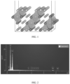
FIG. 1 is a schematic diagram of a crystal structure of a positive electrode material according to an embodiment of this application. -
FIG. 2 is an EDX spectrum of a positive electrode material in Example 3 of this application. -
FIG. 3 is a SEM image of the positive electrode material in Example 3 of this application. -
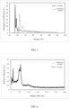
FIG. 4 shows XRD spectra of positive electrode materials in Example 8 and Comparative example 1 of this application. -
FIG. 5 shows X-ray absorption near edge structure spectra of the positive electrode materials in Example 8 and Comparative example 1 of this application. -
FIG. 6 shows Raman spectra of the positive electrode materials in Example 8 and Comparative example 1 of this application. - To make the objectives, technical solutions, and advantages of this application clearer, the following clearly and completely describes the technical solutions in this application with reference to some embodiments. Apparently, the described embodiments are some but not all embodiments of this application. Relevant embodiments described herein are illustrative and used to provide a basic understanding of this application. Some embodiments of this application should not be construed as limitations on this application.
- For brevity, this specification specifically discloses only some numerical ranges. However, any lower limit can be combined with any upper limit to form a range not explicitly recorded, and any lower limit can be combined with another lower limit to form a range not explicitly recorded, and likewise, any upper limit can be combined with any other upper limit to form a range not explicitly recorded. In addition, each individually disclosed point or individual single numerical value itself can be a lower limit or an upper limit which can be combined with any other point or individual numerical value or combined with another lower limit or upper limit to form a range not explicitly recorded.
- In the description of this specification, "more than" or "less than" is inclusive of the present number, unless otherwise specified.
- Unless otherwise specified, the terms used in this application have well known meanings as commonly understood by persons skilled in the art. Unless otherwise specified, numerical values of parameters mentioned in this application may be measured by using various measurement methods commonly used in the art (for example, they may be tested by using the methods provided in some embodiments of this application).
- A list of items connected by the terms "at least one of", "at least one piece of", "at least one type of", or other similar terms may mean any combination of the listed items. For example, if items A and B are listed, the phrase "at least one of A or B" means only A, only B, or A and B. In another example, if items A, B, and C are listed, the phrase "at least one of A, B, or C" means only A, only B, only C, A and B (excluding C), A and C (excluding B), B and C (excluding A), or all of A, B, and C. The item A may include a single constituent or a plurality of constituents. The item B may include a single constituent or a plurality of constituents. The item C may include a single constituent or a plurality of constituents.
- According to a first aspect, this application provides a positive electrode material including a substrate and a first region located on a surface of the substrate, where a molar ratio of iodine element to nickel element in the first region is 0.25 to 1.5. The capacity of a ternary positive electrode material is primarily generated through valence changes of the nickel element and cobalt element. Under deep lithium deintercalation, oxygen ions on a material surface have high activity, easily causing side reactions with an electrolyte. This easily causes formation of spinel on the material surface, inhibiting diffusion of lithium ions. In addition, the side reactions on the surface further increase interface impedance and also cause gas production on the material surface. The inventors of this application have found through research that lithium iodate can be locally formed by introducing iodine ion lattice doping into a surface layer of the positive electrode material and controlling the molar ratio of the iodine element to the nickel element to be 0.25 to 1.5. With extremely strong oxidation resistance, lithium iodate can serve as an external protective layer to improve the stability of an interface between the positive electrode material and the electrolyte under high temperatures and high voltages, thereby inhibiting gas production in high-temperature and high-voltage storage of the electrochemical device and improving the high-temperature cycling performance of the electrochemical device. In addition, it can reduce a valence state of a redox couple of a surface transition metal, increase electron hopping paths, and enhance the electronic conductivity, thereby improving the kinetic performance of the positive electrode material and therefore reducing temperature rise of the electrochemical device under large-rate charge/discharge conditions.
- According to some embodiments of this application, the molar ratio of the iodine element to the nickel element in the first region is 0.3, 0.4, 0.45, 0.55, 0.6, 0.65, 0.7, 0.75, 0.8, 0.85, 0.9, 0.95, 1.0, 1.05, 1.1, 1.15, 1.2, 1.25, 1.3, 1.35, 1.4, 1.45, or a range defined by any two of these values. In some embodiments, the molar ratio of the iodine element to the nickel element in the first region is 0.5 to 1.5.
- The "first region" in this application may refer to a region from an outer surface of the positive electrode material to a depth of 100 nm in the positive electrode material.
- According to some embodiments of this application, the first region includes a second region, where the second region includes lithium iodate.
- According to some embodiments of this application, the first region further includes a third region, where the third region includes nickel iodide.
- In some embodiments, the third region is located between the substrate and the second region. In this case, the outward second region including lithium iodate has stronger oxidation resistance and thus can further improve the stability of the interface between the positive electrode material and the electrolyte under high temperatures and high voltages, thereby inhibiting gas production in high-temperature and high-voltage storage of the electrochemical device and improving the high-temperature cycling performance of the electrochemical device.
- According to some embodiments of this application, a thickness of the second region is H2, where 10 nm ≤ H2 ≤60 nm. In some embodiments, H2 is 13 nm, 15 nm, 17 nm, 20 nm, 23 nm, 25 nm, 27 nm, 27 nm, 29 nm, 32 nm, 35 nm, 37 nm, 40 nm, 43 nm, 45 nm, 47 nm, 50 nm, 53 nm, 55 nm, 57 nm, 59 nm, or a range defined by any two of these values.
- According to some embodiments of this application, a thickness of the third region is H3, where 2 nm ≤ H3 ≤ 60 nm. In some embodiments, H3 is 3 nm, 5 nm, 7 nm, 9 nm, 10 nm, 12 nm, 15 nm, 17 nm, 20 nm, 23 nm, 25 nm, 27 nm, 29 nm, 32 nm, 35 nm, 37 nm, 40 nm, 43 nm, 45 nm, 47 nm, 50 nm, 55 nm, or a range defined by any two of these values.
- In this case, the appropriate thicknesses of the second region and the third region can reduce impact on energy density of the electrochemical device while improving the stability of the interface between the positive electrode material and the electrolyte under high temperatures and high voltages.
- According to some embodiments of this application, within a region from a surface of the positive electrode material to a depth of 2 µm away from the surface of the positive electrode material, along a depth direction of the positive electrode material, the molar ratio of the iodine element to the nickel element gradually decreases.
- According to some embodiments of this application, in an XRD spectrum of the positive electrode material, a characteristic peak is present when 2θ is within a range of 25.0° to 26.0°. In this application, the peak present when 2θ is within the range of 25.0° to 26.0° is a diffraction peak of lithium iodate on the surface. In this case, the lithium iodate on the surface can better protect the surface of the substrate, improving the stability of the interface between the positive electrode material and the electrolyte under high temperatures and high voltages, thereby inhibiting gas production in high-temperature and high-voltage storage of the electrochemical device and improving the high-temperature cycling performance of the electrochemical device.
- According to some embodiments of this application, in the XRD spectrum of the positive electrode material, a peak intensity ratio of the characteristic peak present when 2θ is within the range of 25.0° to 26.0° to a characteristic peak present when 2θ is within a range of 17.0° to 19.0° is 0.1 to 0.3. In this application, the peak present when 2θ is within the range of 17.0° to 19.0° is a diffraction peak of the substrate.
- According to some embodiments of this application, a Raman spectrum of the positive electrode material has Raman shift peaks within a range of 100 cm-1 to 140 cm-1 and a range of 50 cm-1 to 90 cm-1. In this application, the Raman shift peak within the range of 100 cm-1 to 140 cm-1 represents a characteristic peak of the substrate, and the Raman shift peak within the range of 50 cm-1 to 90 cm-1 represents a characteristic peak of lithium iodate. This indicates that lithium iodate is present on the surface of the substrate, thereby improving the surface stability of the positive electrode material.
- According to some embodiments of this application, an X-ray absorption near edge structure spectrum of the positive electrode material has absorption peaks within a range of 56 eV to 58 eV and a range of 60 eV to 62 eV. In this application, the absorption peak within the range of 56 eV to 58 eV represents lithium iodate, and the absorption peak within the range of 60 eV to 62 eV represents the substrate. This indicates that lithium iodate is present on the surface of the substrate, thereby improving the surface stability of the positive electrode material.
- According to some embodiments of this application, based on a mass of the positive electrode material, a mass percentage of the iodine element is 0.2% to 5%. The percentage of the iodine element being within the above range can improve the stability of the interface between the positive electrode material and the electrolyte under high temperatures and high voltages, thereby inhibiting gas production in high-temperature and high-voltage storage of the electrochemical device and improving the high-temperature cycling performance of the electrochemical device. In addition, this can reduce a valence state of a redox couple of a surface transition metal, increase electron hopping paths, and enhance the electronic conductivity, thereby improving the kinetic performance of the positive electrode material and therefore reducing temperature rise of the electrochemical device under large-rate charge/discharge conditions.
- According to some embodiments of this application, based on the mass of the positive electrode material, a mass percentage of lithium element is greater than or equal to 5%. In some embodiments, based on the mass of the positive electrode material, the mass percentage of the lithium element is less than or equal to 8%.
- According to some embodiments of this application, based on the mass of the positive electrode material, the mass percentage of nickel element is greater than or equal to 30%. In some embodiments, based on the mass of the positive electrode material, the mass percentage of the nickel element is less than or equal to 60%.
- This application further provides a preparation method of the foregoing positive electrode material. The preparation method includes mixing and roasting the substrate of the positive electrode material with lithium iodide to obtain the positive electrode material. According to some embodiments of this application, the roasting is performed at a temperature of 300°C to 700°C, for example, 350°C, 450°C, 550°C, or 650°C. In some embodiments, the roasting is performed at a temperature of 400°C to 600°C. In some embodiments, the roasting is performed in an inert atmosphere, for example, a nitrogen atmosphere.
- According to some embodiments of this application, a total molar number of metal elements other than Li in the substrate is nM, a molar number of Ni element in the substrate is nNi, a molar number of Co element in the substrate is nCo, and a molar number of R element in the substrate is nR, wherein 0 < nNi/nM ≤ 1, 0 ≤ nCo/nM < 1, 0 ≤ nR/nM < 1, and the R element includes at least one of sodium (Na), magnesium (Mg), aluminum (Al), titanium (Ti), zirconium (Zr), niobium (Nb), yttrium (Y), chromium (Cr), vanadium (V), germanium (Ge), molybdenum (Mo), iron (Fe), copper (Cu), zinc (Zn), gallium (Ga), silver (Ag), tungsten (W), indium (In), tin (Sn), lead (Pb), antimony (Sb), lanthanum (La), cerium (Ce), calcium (Ca), or strontium (Sr). According to some embodiments of this application, 0.5 ≤ nNi/nM≤1, 0 ≤ nCo/nM ≤ 0.5, and 0 ≤ nR/nM ≤ 0.5.
- According to a second aspect, this application provides an electrochemical device including a positive electrode. The positive electrode includes a positive electrode current collector and a positive electrode active material layer, where the positive electrode active material layer includes the positive electrode material according to the first aspect.
- According to some embodiments of this application, the positive electrode active material layer further includes a conductive agent and a binder. In some embodiments, the binder includes but is not limited to polyvinyl alcohol, hydroxypropyl cellulose, diacetyl cellulose, polyvinyl chloride, carboxylated polyvinyl chloride, polyvinylpyrrolidone, polyurethane, polytetrafluoroethylene, polyvinylidene fluoride, styrene-butadiene rubber, or acrylic (acrylated) styrene-butadiene rubber. In some embodiments, the conductive agent includes but is not limited to a carbon-based material, a metal-based material, a conductive polymer, and a mixture thereof. In some embodiments, the carbon-based material is selected from graphite, carbon black, acetylene black, Ketjen black Carbon nanotubes, carbon fiber, graphene, or any combination thereof. In some embodiments, the metal-based material is selected from metal powder, metal fiber, copper, nickel, aluminum, or silver. In some embodiments, the conductive polymer is a polyphenylene derivative.
- According to some embodiments of this application, the positive electrode further includes a positive electrode current collector. The positive electrode current collector may be a metal foil or a composite current collector. For example, an aluminum foil may be used. The composite current collector may be formed by forming a metal material (copper, copper alloy, nickel, nickel alloy, titanium, titanium alloy, silver, silver alloy, and the like) on a polymer matrix.
- The electrochemical device of this application further includes a negative electrode. The negative electrode includes a negative electrode active material layer and a negative electrode current collector.
- According to some embodiments of this application, the negative electrode active material layer includes a negative electrode active material, a conductive agent and a binder. In some embodiments, the negative electrode active material may include a material for reversibly intercalating/deintercalating lithium ions, lithium metal, lithium metal alloy, or a transition metal oxide. In some embodiments, the negative electrode active material includes at least one of a carbon material or a silicon material. The carbon material includes at least one of graphite or hard carbon. The silicon material includes at least one of silicon, a silicon-oxygen compound, a silicon-carbon compound, or silicon alloy. In some embodiments, the binder may include various binder polymers. In some embodiments, the binder includes at least one of polyvinylidene fluoride, a vinylidene fluoride-hexafluoropropylene copolymer, polyamide, polyacrylonitrile, polyacrylic ester, polyacrylic acid, polyacrylate, sodium carboxymethyl cellulose, polyvinylpyrrolidone, polyvinyl ether, polytetrafluoroethylene, polyhexafluoropropylene, or styrene-butadiene rubber. In some embodiments, any conductive material causing no chemical change can be used as the conductive agent. In some embodiments, the conductive agent includes at least one of conductive carbon black, acetylene black, carbon nanotubes, Ketjen black, carbon fiber, or graphene.
- According to some embodiments of this application, the negative electrode current collector may be copper foil, nickel foil, stainless steel foil, titanium foil, nickel foam, copper foam, a polymer substrate coated with a conductive metal, or a combination thereof.
- The electrochemical device of this application further includes an electrolyte. The electrolyte includes a lithium salt and a non-aqueous solvent.
- In some embodiments of this application, the lithium salt is one or more selected from a group consisting of LiPF6, LiBF4, LiAsF6, LiClO4, LiB(C6H5)4, LiCH3SO3, LiCF3SO3, LiN(SO2CF3)2, LiC(SO2CF3)3, LiSiF6, LiBOB, and lithium difluoroborate. For example, LiPF6 may be used as the lithium salt.
- The non-aqueous solvent may be a carbonate compound, a carboxylate compound, an ether compound, another organic solvent, or a combination thereof.
- The carbonate compound may be a linear carbonate compound, a cyclic carbonate compound, a fluorocarbonate compound, or a combination thereof.
- An example of the linear carbonate compound is dimethyl carbonate (DMC), diethyl carbonate (DEC), dipropyl carbonate (DPC), methyl propyl carbonate (MPC), ethyl propyl carbonate (EPC), ethyl methyl carbonate (MEC), or a combination thereof. An example of the cyclic carbonate compound is ethylene carbonate (EC), propylene carbonate (PC), butylene carbonate (BC), vinyl ethylene carbonate (VEC), or a combination thereof. An example of the fluorocarbonate compound is fluoroethylene carbonate (FEC), 1,2-difluoroethylene carbonate, 1,1-difluoroethylene carbonate, 1,1,2-trifluoroethylene carbonate, 1,1,2,2-tetrafluoroethylene carbonate, 1-fluoro-2-methylethylene carbonate, 1-fluoro-1-methylethylene carbonate, 1,2-difluoro-1-methylethylene carbonate, 1,1,2-trifluoro-2-methylethylene carbonate, trifluoromethylethylene carbonate, or a combination thereof.
- An example of the carboxylate compound is methyl formate, methyl acetate, ethyl acetate, n-propyl acetate, t-butyl acetate, methyl propionate, ethyl propionate, propyl propionate, γ-butyrolactone, decalactone, valerolactone, caprolactone, or a combination thereof.
- An example of the ether compound is dibutyl ether, tetraglyme, diglyme, 1,2-dimethoxyethane, 1,2-diethoxyethane, ethoxymethoxy ethane, 2-methyltetrahydrofuran, tetrahydrofuran, or a combination thereof.
- An example of the another organic solvent is dimethyl sulfoxide, 1,2-dioxolane, sulfolane, methyl sulfolane, 1,3-dimethyl-2-imidazolidinone, N-methyl-2-pyrrolidone, formamide, dimethylformamide, acetonitrile, trimethyl phosphate, triethyl phosphate, trioctyl phosphate, phosphate ester, or a combination thereof.
- According to some embodiments of this application, in this electrochemical device, a separator is disposed between the positive electrode and a negative electrode to prevent short circuits. A material and shape of the separator used in some embodiments of this application are not specifically limited, and any technology disclosed in the prior art may be used for the separator. In some embodiments, the separator includes a polymer, an inorganic substance, or the like formed by a material stable to the electrolyte of this application. For example, the separator may include a substrate layer and a surface treatment layer. The substrate layer is a non-woven fabric, film, or composite film of a porous structure. The substrate layer is made of at least one of polyethylene, polypropylene, polyethylene terephthalate, or polyimide. Specifically, a polypropylene porous film, a polyethylene porous film, polypropylene non-woven fabric, polyethylene non-woven fabric, or a polypropylene-polyethylene-polypropylene porous composite film may be selected. The surface treatment layer is provided on at least one surface of the substrate layer, and the surface treatment layer may be a polymer layer or an inorganic substance layer, or may be a layer formed by mixing a polymer and an inorganic substance. The inorganic substance layer includes inorganic particles and a binder. The inorganic particles include at least one of aluminum oxide, silicon oxide, magnesium oxide, titanium oxide, hafnium dioxide, tin oxide, cerium dioxide, nickel oxide, zinc oxide, calcium oxide, zirconium oxide, yttrium oxide, silicon carbide, boehmite, aluminum hydroxide, magnesium hydroxide, calcium hydroxide, or barium sulfate. The binder includes at least one of polyvinylidene fluoride, a vinylidene fluoride-hexafluoropropylene copolymer, polyamide, polyacrylonitrile, polyacrylate, polyacrylic acid, polyacrylate, polyvinylpyrrolidone, polyvinyl ether, polymethyl methacrylate, polytetrafluoroethylene, or polyhexafluoropropylene. The polymer layer contains a polymer, and a material of the polymer includes at least one of polyamide, polyacrylonitrile, acrylate polymer, polyacrylic acid, polyacrylate, polyvinylpyrrolidone, polyvinyl ether, polyvinylidene fluoride, or poly(vinylidene fluoride-hexafluoropropylene).
- According to some embodiments of this application, the electrochemical device of this application includes but is not limited to all types of primary batteries or secondary batteries. In some embodiments, the electrochemical device is a lithium secondary battery. In some embodiments, the lithium secondary battery includes but is not limited to a lithium metal secondary battery, a lithium-ion secondary battery, a lithium polymer secondary battery, or a lithium-ion polymer secondary battery.
- According to a third aspect, an electronic device of this application may be any apparatus using the electrochemical device according to the second aspect.
- In some embodiments, the electronic device includes but is not limited to a notebook computer, a pen-input computer, a mobile computer, an e-book player, a portable phone, a portable fax machine, a portable copier, a portable printer, a head-mounted stereo headset, a video recorder, a liquid crystal display television, a portable cleaner, a portable CD player, a mini disc, a transceiver, an electronic notebook, a calculator, a storage card, a portable recorder, a radio, a backup power supply, a motor, an automobile, a motorcycle, a motor bicycle, a bicycle, a lighting apparatus, a toy, a game console, a clock, an electric tool, a flashlight, a camera, a large household storage battery, or a lithium-ion capacitor.
-
Step 1. A solution mixture containing NiSO4 and CoSO4 was prepared according to a molar ratio of elements Ni:Co=98:2; and the solution mixture was mixed with a precipitant (NaOH solution) and a complexing agent (ammonia water) for reaction, where a reaction time was controlled to be 40 hours, a concentration of the ammonia water was controlled to be 2.5 mol/L, and PH was controlled to be 13, to obtain a ternary precursor Ni0.98Co0.02(OH)2. - Step 2. The ternary precursor Ni0.98Co0.02(OH)2 obtained in
Step 1 and lithium hydroxide were ground and mixed to uniformity at a molar ratio of 1:1.05; and the resulting mixture was calcined in an oxygen atmosphere at 680°C for 20 h, cooled down to room temperature at a rate of 10°C/min, and ultimately crushed and sieved to obtain a positive electrode material intermediate LiNi0.98Co0.02O2. - Step 3. The positive electrode material intermediate LiNi0.98Co0.02O2 obtained in Step 2 was mixed with LiI at a specified ratio (a specific mixing ratio is shown in Table 1, where an amount of LiI added was relative to a mass of the positive electrode material intermediate), and after mixing, the resulting mixture was sintered in an N2 environment at a specified temperature (a specific temperature is shown in Table 1) to obtain a positive electrode material.
Table 1 Examples and Comparative examples Chemical formula of positive electrode material intermediate Amount of LiI added (%) Sintering temperature in step 3 (°C) Example 1 LiNi0.98Co0.02O2 0.3 400 Example 2 LiNi0.98Co0.02O2 0.3 500 Example 3 LiNi0.98Co0.02O2 0.3 600 Example 4 LiNi0.98Co0.02O2 0.3 700 Example 5 LiNi0.98Co0.02O2 0.5 600 Example 6 LiNi0.98Co0.02O2 0.7 600 Example 7 LiNi0.98Co0.02O2 1.0 600 Example 8 LiNi0.98Co0.02O2 1.4 600 Example 9 LiNi0.98Co0.02O2 1.8 600 Comparative example 1 LiNi0.98Co0.02O2 0.0 - Comparative example 2 LiNi0.98Co0.02O2 0.12 300 Comparative example 3 LiNi0.98Co0.02O2 2.4 600 - A binder polyvinylidene fluoride (PVDF), a conductive agent conductive carbon black (Super P), and the positive electrode material at a weight ratio of (5:5:95) were fully stirred and mixed to uniformity in N-methylpyrrolidone (NMP) to prepare a positive electrode slurry.
- The positive electrode slurry was uniformly applied onto a single side of an aluminum foil, with a coating thickness of 40 µm; and after drying, rolling was performed to form an electrode required, where a surface density of the coated electrode was 14 mg/cm2, and the electrode was punched into a disc with a diameter of 14 mm to form a single-sided electrode plate.
- A separator was punched into a disc with a diameter of 18 mm; a negative electrode used is a lithium metal sheet with a diameter of 18 mm; and propylene carbonate (PC), ethylene carbonate (EC), and diethyl carbonate (DEC) (at a weight ratio of 1:1:1) were mixed to form a solvent, and LiPF6 was added into the solvent and mixed to uniformity to obtain an electrolyte, where based on a mass of the electrolyte, a mass percentage of LiPF6 is 12.5%.
- The positive electrode plate, separator, negative electrode plate (lithium sheet), and other accessories such as the electrolyte and a battery housing were transferred into a glove box (with a water content less than 11 ppm).
- These components were stacked from bottom to top to be assembled into a battery, and the electrolyte was injected into the battery. The battery was packaged in a packaging machine to obtain a button battery.
- A binder polyvinylidene fluoride (PVDF), a conductive agent conductive carbon black (Super P), and the positive electrode material at a weight ratio of (1.5:1.5:97) were fully stirred and mixed to uniformity in N-methylpyrrolidone (NMP) to prepare a positive electrode slurry.
- The positive electrode slurry was uniformly applied onto both sides of an aluminum foil, with a coating thickness of 40 µm on each side; and after drying, rolling was performed to form an electrode required, where a surface density of the coated electrode was 14 mg/cm2.
- Artificial graphite, styrene-butadiene rubber, and sodium carboxymethylcellulose (CMC) at a mass ratio of 96:2:2 were mixed with deionized water and well stirred to obtain a negative electrode slurry. The negative electrode slurry was applied onto a copper foil with a thickness of 12 µm. Drying and cold pressing were performed, followed by cutting and tab welding to obtain a negative electrode.
- In a dry argon environment, propylene carbonate (PC), ethylene carbonate (EC), and diethyl carbonate (DEC) (at a weight ratio of 1:1:1) were mixed to form a solvent, and LiPF6 was added into the solvent and mixed to uniformity to obtain an electrolyte, where based on a mass of the electrolyte, a mass percentage of LiPF6 is 12.5%.
- A polyethylene (PE) porous polymer film was used as a separator.
- The positive electrode, separator, and negative electrode were stacked in sequence, ensuring that the separator was located between the positive electrode and the negative electrode for separation. Then, winding was performed to obtain an electrode assembly. The electrode assembly was placed into an outer packaging aluminum-plastic film, followed by electrolyte injection and packaging. Through processes such as formation, degassing, and edge trimming, a lithium-ion pouch battery was obtained.
- A concentration and molar ratio of Ni and I elements at a depth of 0 to 100 nm were measured using an XPS method in combination with ion polishing.
- Contents of the elements were measured through an ICP test.
- The lithium-ion battery was fully discharged to a voltage below 3.5V at a current density of 10 mA/cm2, left standing for 10 min, and then disassembled in a glove box to obtain a positive electrode plate; and the positive electrode plate was transferred to a chamber of a scanning electron microscope (Model: FEI Vion Plasma FIB) provided with focused ion beams, and was processed to obtain a sample for analysis by a transmission scanning electron microscope (STEM, model: FEI Titan3 G2 60-300). A surface of the sample was protected with Pt and was processed using a Ga ion beam, ensuring that a thickness of the sample was not greater than 100 nm; and the sample was cleaned in a low-voltage mode to remove residual surface from the sample during processing.
- The sample was observed under a STEM, and thicknesses of the second region and third region were measured. Thicknesses of at least three positions were collected, and an average value was taken.
- An XRD spectrum of the positive electrode material was obtained through an XRD diffraction test, where when 2θ was within a range of 25.0° to 26.0°, a strongest peak intensity was I1, when 2θ was within a range of 17.0° to 19.0°, a strongest peak intensity was I2, and an XRD peak intensity ratio is equal to I1/I2.
- A Raman spectrometer and an X-ray absorption near edge structure spectrometer were used to test the positive electrode material, for determining whether there was a Raman shift peak within a range of 50 cm-1 to 90 cm-1 in a Raman spectrum and whether there was an absorption peak within a range of 56 eV to 58 eV in an X-ray absorption near edge structure spectrum.
- The lithium-ion pouch battery was charged to 4.35 V at 0.5C at 25°C and then charged to 0.05C at the constant voltage of 4.35 V; a thickness of the lithium-ion battery at that time was measured using a micrometer and recorded as H11; after that, the lithium-ion battery was stored in an oven at 85°C for 12 hours; and 12 hours later, a thickness of the lithium-ion battery at that time was measured using the micrometer and recorded as H12.
- Thickness swelling rate of lithium-ion battery after 12 hours of storage at

- The lithium-ion pouch battery was placed in a thermostat at 45°C, and left standing for 30 min until the lithium-ion battery reached a constant temperature; the lithium-ion battery reaching a constant temperature was charged to 4.35 V at a constant current of 1.5C at 45°C, charged to 0.02C at a constant voltage of 4.35 V, and then discharged to 3.0 V at a constant current of 4C; a discharge capacity in this cycle was measured and recorded as the first cycle discharge capacity; the battery was charged/discharged in this way for 300 cycles; and a discharge capacity at the 300th cycle of the battery was measured and recorded as the 300th cycle discharge capacity.
Capacity retention rate of lithium-ion battery after 300 cycles at 45°C (%) = 300th cycle discharge capacity/first cycle discharge capacity × 100%. - The lithium-ion pouch battery was placed in a 25°C thermostat and left standing for 30 minutes until the lithium-ion battery reached a constant temperature. The lithium-ion battery reaching a constant temperature was charged to a voltage of 4.35 V at a constant current of 1.5C, and then charged to a current of 0.05C at a constant voltage of 4.35 V Subsequently, the lithium-ion battery was discharged to 3.0 V at 8C. During this process, the lithium-ion battery was wrapped with thermal insulation cotton, and temperatures of the head, tail, and middle of the lithium-ion battery were separately measured using a multi-channel thermometer, and an average value was taken.
- In a 25°C environment, the lithium-ion button battery was charged at a constant current of 0.5C and a constant voltage until an upper limit voltage was 4.25 V, and then discharged at a constant current of 0.2C until a final voltage was 2.8 V; and a discharge capacity of the lithium-ion battery was calculated. A ratio of the discharge capacity of the lithium-ion battery to the mass of the positive electrode material was calculated and recorded as the gram capacity of the lithium-ion battery.
-
Table 2-1 Example Positive electrode material and Comparative example I/Ni molar ratio Percentage of I (%) H2 (nm) H3 (nm) H2+H3 (nm) XRD peak intensity ratio Raman peak from 50 cm-1 to 90 cm-1 Absorption peak from 56 eV to 58 eV Example 1 0.43 0.27 17.2 2.33 19.5 0.11 Found Found Example 2 0.37 0.26 14.6 3.38 18.0 0.10 Found Found Example 3 0.31 0.25 12.2 4.40 16.6 0.11 Found Found Example 4 0.25 0.24 12.8 8.00 20.8 0.12 Found Found Example 5 0.48 0.39 19.2 6.92 26.1 0.13 Found Found Example 6 0.65 0.53 25.9 9.33 35.3 0.14 Found Found Example 7 0.90 0.73 35.6 12.83 48.5 0.16 Found Found Example 8 1.19 0.97 47.3 17.03 64.3 0.26 Found Found Example 9 1.47 1.20 58.3 21.00 79.3 0.29 Found Found Comparative example 1 0.00 0.00 - - - / / / Comparative example 2 0.10 0.10 - - - / / / Comparative example 3 1.80 2.01 60.0 33.0 93.0 0.4 Found Found Note: H2 is the thickness of the second region that includes lithium iodate, and H3 is the thickness of the third region that includes nickel iodide. Table 2-2 Example and Comparative example Lithium-ion battery Thickness swelling rate at 85°C (%) Cycling capacity retention rate at 45°C (%) Discharge temperature rise at 1.5C/8C (°C) Gram capacity at 0.2C at 25°C (mAh/g) Example 1 17 76.7 45 194.0 Example 2 16 76.6 44 194.7 Example 3 14 76.4 43 195.8 Example 4 15 76.8 43 196.7 Example 5 12 77.3 41 198.4 Example 6 10. 78.1 39 201.0 Example 7 8 79.3 37 204.7 Example 8 5 80.7 33 209.2 Example 9 1 82.1 30 213.4 Comparative example 1 39 60 61 165.87 Comparative example 2 35 62.0 58 185.00 Comparative example 3 30 65.0 55 193.00 - From the comparison of Examples 1 to 9 and Comparative examples 1 to 3 in Tables 2-1 and 2-2, it can be seen that when the molar ratio of the iodine element to the nickel element in the surface layer of the positive electrode material is within the range of 0.25 to 1.5, the lithium-ion battery has excellent high-temperature storage performance, excellent high-temperature cycling performance, and low temperature rise under large-rate charge/discharge conditions. It is speculated that a possible reason is that when the molar ratio of the iodine element to the nickel element in the surface layer of the positive electrode material is within the range of 0.25 to 1.5, lithium iodate can be locally formed. With extremely strong oxidation resistance, lithium iodate can serve as an external protective layer to improve the stability of an interface between the positive electrode material and the electrolyte under high temperatures and high voltages, thereby inhibiting gas production in high-temperature and high-voltage storage of the lithium-ion battery and improving the high-temperature cycling performance of the lithium-ion battery. In addition, it can reduce a valence state of a redox couple of a surface transition metal, increase electron hopping paths, and enhance the electronic conductivity, thereby improving the kinetic performance of the positive electrode material and therefore reducing temperature rise of the lithium-ion battery under large-rate charge/discharge conditions.
- When the molar ratio of the iodine element to the nickel element is extremely low (in Comparative example 2), a local lithium iodate coating layer cannot be formed. Therefore, the high-temperature storage performance, high-temperature cycling performance, and rate performance of the lithium-ion battery cannot be effectively improved.
- When the molar ratio of the iodine element to the nickel element is extremely high (in Comparative example 3), although the high-temperature storage performance and high-temperature cycling performance of the lithium-ion battery can be effectively improved, excessive I element forms a heterogeneous structure that coats the surface of the positive electrode active material, hindering the diffusion of lithium ions, thereby leading to severe temperature rise of the lithium-ion battery under large-rate charge/discharge conditions.
- Although some exemplary embodiments of this application have been illustrated and described, this application is not limited to the disclosed embodiments. On the contrary, persons of ordinary skill in the art will recognize that some modifications and changes can be made to the described embodiments without departing from the spirit and scope of this application described in the appended claims.
Claims (11)
- A positive electrode material, comprising a substrate and a first region located on a surface of the substrate, wherein a molar ratio of iodine element to nickel element in the first region is 0.25 to 1.5.
- The positive electrode material according to claim 1, wherein the molar ratio of the iodine element to the nickel element in the first region is 0.5 to 1.5.
- The positive electrode material according to claim 1, wherein the first region comprises a second region, and the second region comprises lithium iodate.
- The positive electrode material according to claim 3, wherein the first region further comprises a third region; the third region comprises nickel iodide; and the positive electrode material satisfies at least one of the following conditions (a) to (c):(a) the third region is located between the substrate and the second region;(b) a thickness of the second region is H2, wherein 10 nm ≤ H2 ≤ 60 nm; or(c) a thickness of the third region is H3, wherein 2 nm ≤ H3 ≤ 60 nm.
- The positive electrode material according to claim 1, wherein within a region from a surface of the positive electrode material to a depth of 2 µm away from the surface of the positive electrode material, along a depth direction of the positive electrode material, the molar ratio of the iodine element to the nickel element gradually decreases.
- The positive electrode material according to claim 1, wherein in an XRD spectrum of the positive electrode material, a characteristic peak is present when 2θ is within a range of 25.0° to 26.0°.
- The positive electrode material according to claim 6, wherein in the XRD spectrum of the positive electrode material, a peak intensity ratio of the characteristic peak present when 2θ is within the range of 25.0° to 26.0° to a characteristic peak present when 2θ is within a range of 17.0° to 19.0° is 0.1 to 0.3.
- The positive electrode material according to claim 1, wherein the positive electrode material satisfies at least one of the following conditions (d) or (e):(d) a Raman spectrum of the positive electrode material has Raman shift peaks within a range of 100 cm-1 to 140 cm-1 and a range of 50 cm-1 to 90 cm-1; or(e) an X-ray absorption near edge structure spectrum of the positive electrode material has absorption peaks within a range of 56 eV to 58 eV and a range of 60 eV to 62 eV.
- The positive electrode material according to claim 1, wherein the positive electrode material satisfies at least one of the following conditions (g) to (i):(f) based on a mass of the positive electrode material, a mass percentage of iodine element is 0.2% to 5%;(g) based on a mass of the positive electrode material, a mass percentage of lithium element is 5% to 8%;(h) based on a mass of the positive electrode material, a mass percentage of nickel element is 30% to 60%;(i) a total molar number of metal elements other than lithium in the substrate is nm, a molar number of nickel element in the substrate is nNi, a molar number of cobalt element in the substrate is nCo, and a molar number of R element in the substrate is nR, wherein 0 < nNi/nM ≤ 1, 0 ≤ nCo/nM < 1, 0 ≤ nR/nM < 1, and the R element includes at least one of sodium, magnesium, aluminum, titanium, zirconium, niobium, yttrium, chromium, vanadium, germanium, molybdenum, iron, copper, zinc, gallium, silver, tungsten, indium, tin, lead, antimony, lanthanum, cerium, calcium, or strontium.
- An electrochemical device, comprising a positive electrode, wherein the positive electrode comprises a positive electrode current collector and a positive electrode active material layer, and the positive electrode active material layer comprises the positive electrode material according to any one of claims 1 to 9.
- An electronic device, comprising the electrochemical device according to claim 10.
Applications Claiming Priority (1)
| Application Number | Priority Date | Filing Date | Title |
|---|---|---|---|
| PCT/CN2022/087693 WO2023201526A1 (en) | 2022-04-19 | 2022-04-19 | Positive electrode material, electrochemical device and electronic device |
Publications (2)
| Publication Number | Publication Date |
|---|---|
| EP4489127A1 true EP4489127A1 (en) | 2025-01-08 |
| EP4489127A4 EP4489127A4 (en) | 2025-11-12 |
Family
ID=88143335
Family Applications (1)
| Application Number | Title | Priority Date | Filing Date |
|---|---|---|---|
| EP22937764.3A Pending EP4489127A4 (en) | 2022-04-19 | 2022-04-19 | POSITIVE ELECTRODE MATERIAL, ELECTROCHEMICAL DEVICE AND ELECTRONIC DEVICE |
Country Status (4)
| Country | Link |
|---|---|
| US (1) | US20250023042A1 (en) |
| EP (1) | EP4489127A4 (en) |
| CN (1) | CN116830311A (en) |
| WO (1) | WO2023201526A1 (en) |
Families Citing this family (1)
| Publication number | Priority date | Publication date | Assignee | Title |
|---|---|---|---|---|
| WO2022139562A1 (en) * | 2020-12-25 | 2022-06-30 | 주식회사 엘지에너지솔루션 | Cathode active material, cathode active material slurry, cathode, lithium ion secondary battery, and method for preparing cathode active material |
Family Cites Families (5)
| Publication number | Priority date | Publication date | Assignee | Title |
|---|---|---|---|---|
| CN101673823B (en) * | 2009-09-24 | 2012-09-26 | 福建师范大学 | Method for preparing lithium iron phosphate cathode material simultaneously blended with nickel and iodine by sintering method |
| US8557438B2 (en) * | 2010-08-25 | 2013-10-15 | Uchicago Argonne, Llc | Electrode materials for rechargeable battery |
| JP6478090B2 (en) * | 2013-09-30 | 2019-03-06 | パナソニックIpマネジメント株式会社 | Non-aqueous electrolyte secondary battery positive electrode active material, non-aqueous electrolyte secondary battery, and method for producing positive electrode active material for non-aqueous electrolyte secondary battery |
| CN109449414A (en) * | 2018-11-01 | 2019-03-08 | 江西中汽瑞华新能源科技有限公司 | A kind of anode composite material of lithium ion battery and the all-solid-state battery containing the material |
| CN113871588B (en) * | 2021-09-13 | 2023-05-05 | 武汉理工大学 | Lithium battery core-shell positive electrode material, lithium battery containing lithium battery core-shell positive electrode material and preparation method of lithium battery |
-
2022
- 2022-04-19 WO PCT/CN2022/087693 patent/WO2023201526A1/en not_active Ceased
- 2022-04-19 CN CN202280010318.0A patent/CN116830311A/en active Pending
- 2022-04-19 EP EP22937764.3A patent/EP4489127A4/en active Pending
-
2024
- 2024-09-30 US US18/902,073 patent/US20250023042A1/en active Pending
Also Published As
| Publication number | Publication date |
|---|---|
| WO2023201526A1 (en) | 2023-10-26 |
| EP4489127A4 (en) | 2025-11-12 |
| CN116830311A (en) | 2023-09-29 |
| US20250023042A1 (en) | 2025-01-16 |
Similar Documents
| Publication | Publication Date | Title |
|---|---|---|
| EP3733609A1 (en) | Positive active material, preparing method thereof, and rechargeable lithium battery including the same | |
| KR101744091B1 (en) | Positive active material for rechargeable lithium battery, method of preparing the same, and rechargeable lithium battery including the same | |
| EP3974391A1 (en) | Cathode active material for lithium secondary battery and method of manufacturing the same | |
| KR100797099B1 (en) | Cathode active material for lithium secondary battery, preparation method thereof, and lithium secondary battery comprising same | |
| EP4394928A1 (en) | Positive electrode material and electrochemical apparatus comprising same, and electronic apparatus | |
| US20240243280A1 (en) | Positive electrode material, electrochemical device, and electronic device | |
| EP3766838B1 (en) | Method of manufacturing a positive active material, and positive electrode and rechargeable lithium battery including the same | |
| EP2395582A1 (en) | Positive active material for rechargeable lithium battery, method of preparing the same, and rechargeable lithium battery including the same | |
| CN109860546B (en) | Cathode material and electrochemical device comprising same | |
| US20120264009A1 (en) | Method for manufacturing positive active material for rechargeable lithium battery and rechargeable lithium battery using same | |
| EP4350811A1 (en) | Lithium transition metal composite oxide, electrochemical device and electronic device | |
| EP2284934A1 (en) | Electrode assembly and lithium secondary battery including the same | |
| EP4382489A1 (en) | Positive active material for rechargeable lithium batteries, preparation method thereof and rechargeable lithium batteries including the same | |
| JP2008159560A (en) | Method for producing positive electrode active material | |
| KR101878920B1 (en) | Positive active material for rechargeable lithium battery, method of preparing the same, and rechargeable lithium battery including the same | |
| EP4428953A1 (en) | Positive electrode active material, positive electrode plate, electrochemical apparatus comprising positive electrode plate, and electronic apparatus | |
| CN117728023A (en) | Secondary battery and electronic device | |
| US20250023042A1 (en) | Positive electrode material, electrochemical device, and electronic device | |
| EP4057382B1 (en) | Cathode active material for lithium secondary battery and lithium secondary battery including the same | |
| EP4140957A1 (en) | Positive active material precursor for rechargeable lithium battery, method for preparing positive active material using the precursor, and positive active material for rechargeable lithium battery | |
| EP2395578A1 (en) | Positive active material for rechargeable lithium battery, rechargeable lithium battering using the same and method for manufacturing the same | |
| CN114784285A (en) | Positive electrode material, and electrochemical device and electronic device comprising same | |
| US20250023029A1 (en) | Positive electrode material, electrochemical apparatus and electric device | |
| US20240239690A1 (en) | Metal hydroxide, positive electrode material, electrochemical device, and electrical device | |
| KR20140115201A (en) | Positive active material for rechargeable lithium battery, and rechargeable lithium battery including the same |
Legal Events
| Date | Code | Title | Description |
|---|---|---|---|
| STAA | Information on the status of an ep patent application or granted ep patent |
Free format text: STATUS: THE INTERNATIONAL PUBLICATION HAS BEEN MADE |
|
| PUAI | Public reference made under article 153(3) epc to a published international application that has entered the european phase |
Free format text: ORIGINAL CODE: 0009012 |
|
| STAA | Information on the status of an ep patent application or granted ep patent |
Free format text: STATUS: REQUEST FOR EXAMINATION WAS MADE |
|
| 17P | Request for examination filed |
Effective date: 20240930 |
|
| AK | Designated contracting states |
Kind code of ref document: A1 Designated state(s): AL AT BE BG CH CY CZ DE DK EE ES FI FR GB GR HR HU IE IS IT LI LT LU LV MC MK MT NL NO PL PT RO RS SE SI SK SM TR |
|
| DAV | Request for validation of the european patent (deleted) | ||
| DAX | Request for extension of the european patent (deleted) | ||
| A4 | Supplementary search report drawn up and despatched |
Effective date: 20251013 |
|
| RIC1 | Information provided on ipc code assigned before grant |
Ipc: H01M 4/525 20100101AFI20251007BHEP Ipc: H01M 4/505 20100101ALI20251007BHEP Ipc: H01M 4/1315 20100101ALI20251007BHEP Ipc: H01M 4/485 20100101ALI20251007BHEP Ipc: H01M 10/0525 20100101ALI20251007BHEP Ipc: C01G 53/42 20250101ALI20251007BHEP |