EP4489052A1 - Discharge lamp and processing device - Google Patents
Discharge lamp and processing device Download PDFInfo
- Publication number
- EP4489052A1 EP4489052A1 EP24157505.9A EP24157505A EP4489052A1 EP 4489052 A1 EP4489052 A1 EP 4489052A1 EP 24157505 A EP24157505 A EP 24157505A EP 4489052 A1 EP4489052 A1 EP 4489052A1
- Authority
- EP
- European Patent Office
- Prior art keywords
- tube
- discharge lamp
- protection tube
- luminous tube
- luminous
- Prior art date
- Legal status (The legal status is an assumption and is not a legal conclusion. Google has not performed a legal analysis and makes no representation as to the accuracy of the status listed.)
- Pending
Links
Images


Classifications
-
- H—ELECTRICITY
- H01—ELECTRIC ELEMENTS
- H01J—ELECTRIC DISCHARGE TUBES OR DISCHARGE LAMPS
- H01J61/00—Gas-discharge or vapour-discharge lamps
- H01J61/02—Details
- H01J61/30—Vessels; Containers
- H01J61/34—Double-wall vessels or containers
-
- C—CHEMISTRY; METALLURGY
- C02—TREATMENT OF WATER, WASTE WATER, SEWAGE, OR SLUDGE
- C02F—TREATMENT OF WATER, WASTE WATER, SEWAGE, OR SLUDGE
- C02F1/00—Treatment of water, waste water, or sewage
- C02F1/30—Treatment of water, waste water, or sewage by irradiation
- C02F1/32—Treatment of water, waste water, or sewage by irradiation with ultraviolet light
- C02F1/325—Irradiation devices or lamp constructions
-
- H—ELECTRICITY
- H01—ELECTRIC ELEMENTS
- H01J—ELECTRIC DISCHARGE TUBES OR DISCHARGE LAMPS
- H01J5/00—Details relating to vessels or to leading-in conductors common to two or more basic types of discharge tubes or lamps
- H01J5/48—Means forming part of the tube or lamp for the purpose of supporting it
-
- F—MECHANICAL ENGINEERING; LIGHTING; HEATING; WEAPONS; BLASTING
- F21—LIGHTING
- F21V—FUNCTIONAL FEATURES OR DETAILS OF LIGHTING DEVICES OR SYSTEMS THEREOF; STRUCTURAL COMBINATIONS OF LIGHTING DEVICES WITH OTHER ARTICLES, NOT OTHERWISE PROVIDED FOR
- F21V15/00—Protecting lighting devices from damage
- F21V15/04—Resilient mountings, e.g. shock absorbers
-
- H—ELECTRICITY
- H01—ELECTRIC ELEMENTS
- H01J—ELECTRIC DISCHARGE TUBES OR DISCHARGE LAMPS
- H01J61/00—Gas-discharge or vapour-discharge lamps
- H01J61/82—Lamps with high-pressure unconstricted discharge having a cold pressure > 400 Torr
Definitions
- Embodiments of the present invention relate to a discharge lamp and a processing device.
- a discharge lamp that radiates light such as ultraviolet light.
- a discharge lamp may be used, for example, in a processing device that causes a chemical reaction such as a polymerization reaction.
- the discharge lamp is immersed in a liquid to be treated stored in a treatment tank. Therefore, the discharge lamp has, for example, a double tube structure including a luminous tube and a protection tube.
- the luminous tube that generates light is provided inside the protection tube. Therefore, the liquid can be inhibited from reaching the luminous tube by the protection tube.
- an electrode is provided at each of ends on both sides of the luminous tube. Since the discharge lamp is immersed in the liquid, it is necessary to supply power to a pair of electrodes from the end side of the discharge lamp located outside the treatment tank. Therefore, a wire for supplying power to an electrode provided on the end side of the luminous tube located inside the treatment tank is provided between an inner wall of the protection tube and an outer wall of the luminous tube. Further, a holding material for holding the wire is provided between the inner wall of the protection tube and the outer wall of the luminous tube. The wire and the holding material extend in a tube axis direction of the protection tube (luminous tube).
- vibration may be applied to the discharge lamp when transporting the discharge lamp or attaching the discharge lamp to the treatment tank.
- vibration may be applied to the discharge lamp via the treatment tank, etc.
- the holding material may vibrate and collide with at least one of the luminous tube and the protection tube. In this case, a light emission length of the discharge lamp provided in the processing device becomes longer, and thus a length of the holding material becomes longer. As the length of the holding material increases, the amplitude of the holding material increases, so that the holding material easily collides with the luminous tube and the protection tube.
- the holding material is made of quartz glass, etc.
- the mass becomes large. Therefore, a speed at which the holding material collides with the luminous tube and the protection tube increases, and at least one of the luminous tube and the protection tube may be damaged.
- a problem to be solved by the invention is to provide a discharge lamp and a processing device that can suppress damage to at least one of a luminous tube and a protection tube when vibration is applied to the discharge lamp.
- a discharge lamp includes: a protection tube having a tubular shape and extending in a first direction; a luminous tube provided inside the protection tube and extending in the first direction; a first electrode provided at a first end of the luminous tube; a second electrode provided at a second end of the luminous tube facing the first end; a first holder provided inside the protection tube to hold the first end of the luminous tube; a second holder provided inside the protection tube to hold the second end of the luminous tube; a first wire provided inside the protection tube and electrically connected to the first electrode; a second wire provided inside the protection tube and electrically connected to the second electrode; a holding material extending in the first direction between the first holder and the second holder inside the protection tube and holding the second wire; and at least one support portion provided between the first holder and the second holder inside the protection tube to support the holding material.
- the support portion includes: a holding portion having a tubular shape and provided with the holding material; and an arm surrounding an outer wall of the luminous tube in a second direction
- a discharge lamp and a processing device that can suppress damage to at least one of a luminous tube and a protection tube when vibration is applied to the discharge lamp.
- the discharge lamp having a double tube structure including a luminous tube having an interior space for generating light and a protection tube having an interior space in which the luminous tube is stored.
- the discharge lamp may have a multi-tube structure.
- the discharge lamp may be a discharge lamp having a triple tube structure further including a tube between the luminous tube and the protection tube.
- FIG. 1 is a schematic partial cross-sectional view illustrating a discharge lamp 1 according to this embodiment.
- the discharge lamp 1 can include, for example, a light-emitting portion 2, a protection tube 3, a holder 4 (corresponding to an example of a first holder and a second holder), a power supply portion 5, and a support portion 6.
- the light-emitting portion 2 can be, for example, a so-called high-intensity discharge (HID) lamp such as a mercury lamp, a metal halide lamp, or a high-pressure sodium lamp.
- HID high-intensity discharge
- the light-emitting portion 2 is not limited to the HID lamp.
- a light emission length of the discharge lamp 1 can be, for example, 2000 mm or more.
- the light emission length is, for example, a distance between tips of a pair of electrodes 22 (corresponding to an example of a first electrode and a second electrode).
- a rated lamp voltage of the discharge lamp 1 is, for example, about 2400 V.
- the rated current of the discharge lamp 1 is, for example, about 4.5 A.
- the light-emitting portion 2 includes, for example, a luminous tube 21, the electrodes 22, an outer lead 23, and a base 24.
- the luminous tube 21 has, for example, a cylindrical shape.
- the luminous tube 21 has a longer length in a tube axis direction (a direction in which the luminous tube 21 extends; this corresponds to an example of a first direction) than a tube outer diameter.
- Both ends of the luminous tube 21 (corresponding to an example of a first end and a second end) are sealed.
- the both ends of the luminous tube 21 can be sealed using, for example, a pinch seal method or a shrink seal method.
- the interior space of the luminous tube 21 is enclosed with a discharge medium for generating light having a predetermined wavelength.
- a wavelength of light radiated from the light-emitting portion 2 can be changed depending on the composition of the discharge medium.
- the discharge medium can include a rare gas such as argon gas and mercury.
- the discharge medium may further include metal halides including iron, tin, iodine, etc.
- the luminous tube 21 is made of quartz glass.
- the luminous tube 21 can be made of transparent, that is, uncolored quartz glass.
- An outer diameter dimension of the luminous tube 21 is, for example, about 28 mm.
- the pair of electrodes 22 is provided facing each other.
- the electrodes 22 are held in sealed parts at the ends of the luminous tube 21.
- One end side of the electrode 22 has a coil shape and is provided in an internal space of the luminous tube 21.
- the other end of the electrode 22 has a linear shape and is provided inside a sealed part of the luminous tube 21.
- the electrode 22 contains, for example, tungsten or thoriated tungsten as a main component.
- the outer lead 23 has a linear shape, and one outer lead 23 is provided for one electrode 22. One end of the outer lead 23 is provided inside a sealed part of the luminous tube 21. Moreover, molybdenum foil is provided inside a sealed part of the luminous tube 21. The electrode 22 and the outer lead 23 are electrically connected to each other via the molybdenum foil.
- the outer lead 23 contains molybdenum as a main component.
- One base 24 is provided for one outer lead 23.
- the base 24 has a cylindrical shape, one end thereof is closed, and the other end thereof is open.
- a hole for passing a wire 52 is provided at the closed-side end of the base 24.
- An end of the sealed part of the luminous tube 21 is provided at the open-side end of the base 24.
- the outer lead 23 and the wire 52 are electrically connected to each other.
- the inside of the base 24 is filled with an insulating material containing aluminum oxide, etc.
- the base 24 can be formed using metal such as stainless steel.
- the protection tube 3 has, for example, a cylindrical shape. Ends on both sides of the protection tube 3 are closed. An internal space of the protection tube 3 is filled with nitrogen or an inert gas such as a rare gas.
- an end of the protection tube 3 where a power supply pin 51 is provided is provided outside the treatment tank 101, and an end on the opposite side thereof is provided inside the treatment tank 101 (for example, see FIG. 5 ).
- the protection tube 3 has a longer length in the tube axis direction (a direction in which the protection tube 3 extends) than the tube outer diameter.
- the light-emitting portion 2 is provided inside the protection tube 3.
- the tube axis direction of the luminous tube 21 can be approximately parallel to the tube axis direction of the protection tube 3.
- an inner diameter of the protection tube 3 is larger than an outer diameter of the luminous tube 21.
- a length of the protection tube 3 in the tube axis direction is longer than a length of the luminous tube 21 in the tube axis direction.
- An external shape dimension of the protection tube 3 is, for example, about 60 mm.
- the protection tube 3 can be formed using borosilicate glass. Note that, for example, a material of the protection tube 3 can be made the same as a material of the luminous tube 21.
- a pair of holders 4 can be provided inside the protection tube 3. Inside the protection tube 3, for example, the holders 4 hold the ends of the luminous tube 21. In this case, for example, the holders 4 can hold the sealed parts of the luminous tube 21.
- the holders 4 include, for example, a disc-shaped member and an elastic member such as a leaf spring. When the elastic member is provided, the light-emitting portion 2 (luminous tube 21) and the protection tube 3 can be protected from thermal expansion and contraction caused by turning on and off the discharge lamp 1, vibrations applied to the discharge lamp 1, etc.
- the holders 4 can be formed from a heat-resistant material.
- the holders 4 are made of stainless steel.
- the power supply portion 5 includes, for example, the power supply pin 51, the wire 52 (corresponding to an example of a first wire), a wire 53 (corresponding to an example of a second wire), and a holding material 54.
- a pair of power supply pins 51 is provided (for example, see FIG. 5 ). Note that FIG. 1 is the case where the discharge lamp 1 is viewed from a direction in which the pair of power supply pins 51 is arranged.
- the pair of power supply pins 51 is provided at one end of the protection tube 3.
- the pair of power supply pins 51 extends in the tube axis direction of the protection tube 3.
- One end of each of the power supply pins 51 is provided outside the protection tube 3.
- the other end of each of the power supply pins 51 is provided inside the protection tube 3.
- the power supply pins 51 can be formed using copper, etc.
- the wire 52 is provided inside the protection tube 3. One end of the wire 52 is electrically connected to the outer lead 23 inside one base 24. That is, the wire 52 is electrically connected to one electrode 22 via the outer lead 23. The other end of the wire 52 is electrically connected to one power supply pin 51.
- the wire 53 is provided inside the protection tube 3. As illustrated in FIG. 1 , the wire 53 extends in the tube axis direction of the luminous tube 21 between the holders 4 inside the protection tube 3. One end of the wire 53 is electrically connected to the outer lead 23 inside the other base 24. That is, the wire 53 is electrically connected to the other electrode 22 via the outer lead 23. The other end of the wire 53 is electrically connected to the other power supply pin 51.
- the wire 52 and the wire 53 can be conductors having a wire diameter of about 0.05 to 2.0 mm.
- the wires 52 and 53 can be, for example, nickel wires, tungsten wires, rhenium wires, molybdenum wires, tantalum wires, alloy wires containing these metals as main components (for example, tungsten-rhenium alloy wires), etc.
- the holding material 54 holds the wire 53.
- the holding material 54 has a tubular shape and extends in the tube axis direction of the luminous tube 21 between the holders 4 inside the protection tube 3.
- the wire 53 can be provided inside the holding material 54 having the tubular shape. The wire 53 extends inside the holding material 54 in the tube axis direction of the luminous tube 21.
- the holding material 54 may have a columnar shape and extend inside the protection tube 3 in the tube axis direction of the luminous tube 21.
- the wire 53 can be held on an outer surface of the holding material 54.
- the wire 53 extends on an outer surface of the holding material 54 in the tube axis direction of the luminous tube 21.
- a plurality of anchors each having a linear shape can be provided side by side on the outer surface of the holding material 54, and the wire 53 can be held by the plurality of anchors.
- the holding material 54 is preferably made of a material that can transmit light radiated from the light-emitting portion 2. In this way, it is possible to prevent light radiated from the light-emitting portion 2 from being blocked by the holding material 54. Therefore, efficiency of extracting light radiated from the light-emitting portion 2 can be improved.
- the holding material 54 can be made of, for example, quartz glass or ceramics such as aluminum oxide.
- a cross-sectional dimension of the holding material 54 in a direction perpendicular to a direction in which the holding material 54 extends can be, for example, about 5 mm.
- vibration may be applied to the discharge lamp 1 when the discharge lamp 1 is transported or when the discharge lamp 1 is attached to the treatment tank 101. Further, vibration may be applied to the discharge lamp 1 via the treatment tank 101, etc. When vibration is applied to the discharge lamp 1, the holding material 54 extending inside the protection tube 3 vibrates.
- the ends on both sides of the holding material 54 are held by the holders 4. Further, the light emission length of the discharge lamp 1 is, for example, 2000 mm or more.
- the cross-sectional dimension of the holding material 54 is, for example, about 5 mm. Therefore, vibration tends to occur in the holding material 54, and the amplitude of the generated vibration tends to increase. As the amplitude of the generated vibration increases, the holding material 54 tends to collide with at least one of the luminous tube 21 and the protection tube 3.
- the holding material 54 is made of quartz glass, etc., and thus has a large mass. Therefore, when the holding material 54 collides with at least one of the luminous tube 21 and the protection tube 3, at least one of the luminous tube 21 and the protection tube 3 is likely to be damaged.
- the amplitude of the generated vibration can be reduced by increasing the cross-sectional dimension of the holding material 54 or by changing a material of the holding material 54.
- light radiated from the light-emitting portion 2 is likely to be blocked by the holding material 54. Therefore, a new problem arises in that efficiency of extracting light radiated from the light-emitting portion 2 is reduced.
- the discharge lamp 1 is provided with the support portion 6 that supports the holding material 54.
- the support portion 6 is provided between the holders 4 inside the protection tube 3. At least one support portion 6 can be provided.
- the discharge lamp 1 illustrated in FIG. 1 is provided with a plurality of support portions 6. When the plurality of support portions 6 is provided, the plurality of support portions 6 can be provided side by side in the tube axis direction of the luminous tube 21 at a predetermined interval.
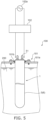
- FIG. 2 is a schematic cross-sectional view of the support portion 6 in a direction of line A-A in FIG. 1 .
- FIG. 3 is a schematic arrow view of the support portion 6 in a direction of line B-B in FIG. 1 .
- the support portion 6 includes, for example, a holding portion 61 and an arm 62.
- the holding portion 61 has a tubular shape, and extends in the tube axis direction of the luminous tube 21.
- the holding material 54 and the wire 53 are provided inside the holding portion 61. Note that as long as the holding material 54 and the wire 53 can be held, a slit extending in the tube axis direction of the luminous tube 21 may be provided in the holding portion 61.
- An inner wall of the holding portion 61 and an outer wall of the holding material 54 may be in contact with each other, or there may be a gap between the inner wall of the holding portion 61 and the outer wall of the holding material 54.
- An outer wall of the holding portion 61 and an inner wall of the protection tube 3 may be in contact with each other, or there may be a gap between the outer wall of the holding portion 61 and the inner wall of the protection tube 3.
- the holding portion 61 can be a cylinder having an outer diameter dimension of about 8 mm, an inner diameter dimension of about 6 mm, and a length of about 12 mm.
- the holding portion 61 is formed from a heat-resistant material.
- the holding portion 61 can be made of, for example, stainless steel or ceramics.
- the arm 62 surrounds the outer wall of the luminous tube 21 in a direction (corresponding to an example of a second direction) perpendicular to the tube axis direction of the luminous tube 21.
- a part of the arm 62 has, for example, an open ring shape (C-shaped ring shape).
- the arm 62 is joined to the holding portion 61.
- an open-side end of the arm 62 is joined to a side surface of the holding portion 61.
- the open-side end of the arm 62 can be welded to the side surface of the holding portion 61.
- the arm 62 is provided between the inner wall of the protection tube 3 and the outer wall of the luminous tube 21.
- the arm 62 and the inner wall of the protection tube 3 may be in contact with each other, or there may be a gap between the arm 62 and the inner wall of the protection tube 3.
- the arm 62 and the outer wall of the luminous tube 21 may be in contact with each other, or there may be a gap between the arm 62 and the outer wall of the luminous tube 21.
- thermal stress generated between the arm 62 and the luminous tube 21 becomes large as the discharge lamp 1 (the light-emitting portion 2) turns on and off.
- the thermal stress becomes excessively large, there is concern that at least one of the arm 62 and the luminous tube 21 may be damaged. Therefore, it is preferable that a gap be provided between the arm 62 and the outer wall of the luminous tube 21 over at least a portion of the entire circumference of the arm 62.
- the arm 62 may have a linear shape or a band shape.
- the length of the arm 62 becomes longer in the tube axis direction of the luminous tube 21, light radiated from the light-emitting portion 2 becomes more likely to be blocked.
- the arm 62 has the linear shape, the length of the arm 62 can be shortened in the tube axis direction of the luminous tube 21. Therefore, it is preferable that the arm 62 is made of a linear member.
- the arm 62 is formed from a heat-resistant material.
- the arm 62 can be made of, for example, a stainless steel wire having a wire diameter of about 1 mm.
- An outer diameter dimension of the arm 62 can be, for example, about 50 mm.
- the holding material 54 and the wire 53 are provided inside the holding portion 61. Therefore, when vibration is applied to the discharge lamp 1, the holding portion 61 comes into contact with the outer wall of the luminous tube 21 or the inner wall of the protection tube 3. In this case, a distance between the holding portion 61 and the outer wall of the luminous tube 21 is smaller than a distance between the holding material 54 and the outer wall of the luminous tube 21. A distance between the holding portion 61 and the inner wall of the protection tube 3 is smaller than a distance between the holding material 54 and the inner wall of the protection tube 3.
- a speed when the holding portion 61 collides with the outer wall of the luminous tube 21 or the inner wall of the protection tube 3 is lower than a speed when the holding material 54 collides with the outer wall of the luminous tube 21 or the inner wall of the protection tube 3.
- the arm 62 comes into contact with at least one of the outer wall of the luminous tube 21 and the inner wall of the protection tube 3 when vibration is applied to the discharge lamp 1. Therefore, since movement of the holding portion 61 is suppressed, it is possible to inhibit the holding portion 61 from colliding with the outer wall of the luminous tube 21 or the inner wall of the protection tube 3, and further reduce the speed at the time of collision.
- the amplitude of a beam increases as a distance between fulcrums increases. Therefore, when the support portion 6 is not provided, the pair of holders 4 serve as fulcrums, so that the amplitude of the holding material 54 increases, and the holding material 54 is likely to collide with the outer wall of the luminous tube 21 or the inner wall of the protection tube 3.
- the support portion 6 when the support portion 6 is provided, the support portion 6 and the holder 4 serve as fulcrums, so that it is possible to inhibit the amplitude of the holding material 54 from increasing. Therefore, when vibration is applied to the discharge lamp 1, it is possible to inhibit the holding material 54 from colliding with the outer wall of the luminous tube 21 or the inner wall of the protection tube 3.
- FIG. 4 is a table for illustrating effects of the support portion 6.
- FIG. 4 is the case where the discharge lamp 1 has the light emission length of 2750 mm, the rated lamp voltage of 2400 V, and the rated current of 4.5 A, the outer diameter dimension of the luminous tube 21 is 28 mm, the external shape dimension of the protection tube 3 is 60 mm, and the cross-sectional dimension of the holding material 54 is 5 mm.
- the number of samples is 9. Further, an effective value of vibration acceleration applied to the discharge lamp 1 is 9.8 m/s 2 .
- the breakage rate of the luminous tube 21 or protection tube 3 can be further reduced.
- the number of support portions 6 is increased, light radiated from the light-emitting portion 2 is likely to be blocked, and thus illuminance of the discharge lamp 1 is likely to decrease.
- L (mm) denotes the light emission length.
- N (pieces) denotes the number of support portions 6.
- N (pieces) is a positive number of 2 or more.
- FIG. 5 is a schematic diagram for illustrating a processing device 100 provided with the discharge lamp 1 according to this embodiment.
- the processing device 100 that causes a chemical reaction such as a polymerization reaction is illustrated as an example.
- the processing device 100 is not limited to one that causes a chemical reaction.
- the processing device 100 can also sterilize water, decompose organic matter contained in water, etc.
- the processing device 100 includes, for example, the treatment tank 101, a lighting device 102, and the discharge lamp 1.
- a liquid 200 to be treated is stored inside the treatment tank 101.
- a region of the discharge lamp 1 where the light-emitting portion 2 is provided is immersed in the liquid 200 stored in the treatment tank 101.
- the discharge lamp 1 can be attached to a ceiling 101a of the treatment tank 101 via a holder 101b so as to be liquid-tight. In this case, the discharge lamp 1 is immersed in the liquid 200 in a substantially vertical posture.
- the discharge lamp 1 can also be provided, for example, on a side surface or at a bottom of the treatment tank 101. When the discharge lamp 1 is provided on the side surface of the treatment tank 101, the discharge lamp 1 is, for example, immersed in the liquid 200 in a substantially horizontal posture.
- the lighting device 102 is provided outside the treatment tank 101.
- the lighting device 102 includes, for example, a step-up transformer and a stabilizer.
- an input side of the lighting device 102 is electrically connected to an AC power source 102a provided in a factory, etc.
- An output side of the lighting device 102 is electrically connected to the power supply pin 51 of the discharge lamp 1 outside the treatment tank 101.
- a discharge occurs between the pair of electrodes 22, and light (for example, ultraviolet light) having a predetermined wavelength depending on the composition of the discharge medium sealed in the internal space of the luminous tube 21 is radiated from the light-emitting portion 2.
- the light radiated from the light-emitting portion 2 is radiated to the liquid 200 via the protection tube 3.
- the liquid 200 is subjected to a predetermined process (for example, a chemical reaction such as a polymerization reaction, a sterilization, decomposition of organic matter, etc.).
Landscapes
- Health & Medical Sciences (AREA)
- Toxicology (AREA)
- Life Sciences & Earth Sciences (AREA)
- Hydrology & Water Resources (AREA)
- Engineering & Computer Science (AREA)
- Environmental & Geological Engineering (AREA)
- Water Supply & Treatment (AREA)
- Chemical & Material Sciences (AREA)
- Organic Chemistry (AREA)
- Vessels And Coating Films For Discharge Lamps (AREA)
- Physical Water Treatments (AREA)
Abstract
[Abstract] Provided are a discharge lamp and a processing device capable of suppressing damage to at least one of a luminous tube and a protection tube when vibration is applied to the discharge lamp.[Problem] A discharge lamp according to an embodiment includes: a protection tube having a tubular shape and extending in a first direction; a luminous tube provided inside the protection tube and extending in the first direction; a first electrode provided at a first end of the luminous tube; a second electrode provided at a second end of the luminous tube facing the first end; a first holder provided inside the protection tube to hold the first end of the luminous tube; a second holder provided inside the protection tube to hold the second end of the luminous tube; a first wire provided inside the protection tube and electrically connected to the first electrode; a second wire provided inside the protection tube and electrically connected to the second electrode; a holding material extending in the first direction between the first holder and the second holder inside the protection tube and holding the second wire; and at least one support portion provided between the first holder and the second holder inside the protection tube to support the holding material. The support portion includes a holding portion having a tubular shape and provided with the holding material; and an arm surrounding an outer wall of the luminous tube in a second direction perpendicular to the first direction and joined to the holding portion.
Description
- Embodiments of the present invention relate to a discharge lamp and a processing device.
- There is a discharge lamp that radiates light such as ultraviolet light. Such a discharge lamp may be used, for example, in a processing device that causes a chemical reaction such as a polymerization reaction. In this case, the discharge lamp is immersed in a liquid to be treated stored in a treatment tank. Therefore, the discharge lamp has, for example, a double tube structure including a luminous tube and a protection tube. In this case, the luminous tube that generates light is provided inside the protection tube. Therefore, the liquid can be inhibited from reaching the luminous tube by the protection tube.
- Further, an electrode is provided at each of ends on both sides of the luminous tube. Since the discharge lamp is immersed in the liquid, it is necessary to supply power to a pair of electrodes from the end side of the discharge lamp located outside the treatment tank. Therefore, a wire for supplying power to an electrode provided on the end side of the luminous tube located inside the treatment tank is provided between an inner wall of the protection tube and an outer wall of the luminous tube. Further, a holding material for holding the wire is provided between the inner wall of the protection tube and the outer wall of the luminous tube. The wire and the holding material extend in a tube axis direction of the protection tube (luminous tube).
- Here, vibration may be applied to the discharge lamp when transporting the discharge lamp or attaching the discharge lamp to the treatment tank. In addition, vibration may be applied to the discharge lamp via the treatment tank, etc. When vibration is applied to the discharge lamp, the holding material may vibrate and collide with at least one of the luminous tube and the protection tube. In this case, a light emission length of the discharge lamp provided in the processing device becomes longer, and thus a length of the holding material becomes longer. As the length of the holding material increases, the amplitude of the holding material increases, so that the holding material easily collides with the luminous tube and the protection tube.
- In this case, since the holding material is made of quartz glass, etc., the mass becomes large. Therefore, a speed at which the holding material collides with the luminous tube and the protection tube increases, and at least one of the luminous tube and the protection tube may be damaged.
- Therefore, it has been desired to develop technology that can suppress damage to at least one of the luminous tube and the protection tube when vibration is applied to the discharge lamp.
- [Patent Literature 1]
JP2002-110101A - A problem to be solved by the invention is to provide a discharge lamp and a processing device that can suppress damage to at least one of a luminous tube and a protection tube when vibration is applied to the discharge lamp.
- A discharge lamp according to an embodiment includes: a protection tube having a tubular shape and extending in a first direction; a luminous tube provided inside the protection tube and extending in the first direction; a first electrode provided at a first end of the luminous tube; a second electrode provided at a second end of the luminous tube facing the first end; a first holder provided inside the protection tube to hold the first end of the luminous tube; a second holder provided inside the protection tube to hold the second end of the luminous tube; a first wire provided inside the protection tube and electrically connected to the first electrode; a second wire provided inside the protection tube and electrically connected to the second electrode; a holding material extending in the first direction between the first holder and the second holder inside the protection tube and holding the second wire; and at least one support portion provided between the first holder and the second holder inside the protection tube to support the holding material. The support portion includes: a holding portion having a tubular shape and provided with the holding material; and an arm surrounding an outer wall of the luminous tube in a second direction perpendicular to the first direction and joined to the holding portion.
- According to the embodiments of the invention, it is possible to provide a discharge lamp and a processing device that can suppress damage to at least one of a luminous tube and a protection tube when vibration is applied to the discharge lamp.
-
- [
FIG. 1 ]
FIG. 1 is a schematic partial cross-sectional view illustrating a discharge lamp according to an embodiment. - [
FIG. 2 ]
FIG. 2 is a schematic cross-sectional view of a support portion in a direction of line A-A inFIG. 1 . - [
FIG. 3 ]
FIG. 3 is a schematic arrow view of the support portion in a direction of line B-B inFIG. 1 . - [
FIG. 4 ]
FIG. 4 is a table for illustrating effects of the support portion. - [
FIG. 5 ]
FIG. 5 is a schematic diagram for illustrating a processing device provided with the discharge lamp according to this embodiment. - Hereinafter, embodiments will be illustrated with reference to the drawings. Note that in each drawing, similar components are denoted by the same reference numerals, and detailed descriptions are omitted as appropriate.
- Hereinafter, as an example, a description will be given of a discharge lamp having a double tube structure including a luminous tube having an interior space for generating light and a protection tube having an interior space in which the luminous tube is stored. However, the discharge lamp may have a multi-tube structure. For example, the discharge lamp may be a discharge lamp having a triple tube structure further including a tube between the luminous tube and the protection tube.
-
FIG. 1 is a schematic partial cross-sectional view illustrating adischarge lamp 1 according to this embodiment. - As illustrated in
FIG. 1 , thedischarge lamp 1 can include, for example, a light-emittingportion 2, aprotection tube 3, a holder 4 (corresponding to an example of a first holder and a second holder), apower supply portion 5, and asupport portion 6. - The light-emitting
portion 2 can be, for example, a so-called high-intensity discharge (HID) lamp such as a mercury lamp, a metal halide lamp, or a high-pressure sodium lamp. However, the light-emittingportion 2 is not limited to the HID lamp. - Further, a light emission length of the
discharge lamp 1 can be, for example, 2000 mm or more. The light emission length is, for example, a distance between tips of a pair of electrodes 22 (corresponding to an example of a first electrode and a second electrode). A rated lamp voltage of thedischarge lamp 1 is, for example, about 2400 V. The rated current of thedischarge lamp 1 is, for example, about 4.5 A. - The light-emitting
portion 2 includes, for example, aluminous tube 21, theelectrodes 22, anouter lead 23, and abase 24. - The
luminous tube 21 has, for example, a cylindrical shape. Theluminous tube 21 has a longer length in a tube axis direction (a direction in which theluminous tube 21 extends; this corresponds to an example of a first direction) than a tube outer diameter. Both ends of the luminous tube 21 (corresponding to an example of a first end and a second end) are sealed. The both ends of theluminous tube 21 can be sealed using, for example, a pinch seal method or a shrink seal method. The interior space of theluminous tube 21 is enclosed with a discharge medium for generating light having a predetermined wavelength. A wavelength of light radiated from the light-emittingportion 2 can be changed depending on the composition of the discharge medium. For example, when ultraviolet light is generated, the discharge medium can include a rare gas such as argon gas and mercury. In addition, the discharge medium may further include metal halides including iron, tin, iodine, etc. - For example, the
luminous tube 21 is made of quartz glass. In this case, for example, theluminous tube 21 can be made of transparent, that is, uncolored quartz glass. An outer diameter dimension of theluminous tube 21 is, for example, about 28 mm. - The pair of
electrodes 22 is provided facing each other. Theelectrodes 22 are held in sealed parts at the ends of theluminous tube 21. One end side of theelectrode 22 has a coil shape and is provided in an internal space of theluminous tube 21. The other end of theelectrode 22 has a linear shape and is provided inside a sealed part of theluminous tube 21. Theelectrode 22 contains, for example, tungsten or thoriated tungsten as a main component. - The
outer lead 23 has a linear shape, and oneouter lead 23 is provided for oneelectrode 22. One end of theouter lead 23 is provided inside a sealed part of theluminous tube 21. Moreover, molybdenum foil is provided inside a sealed part of theluminous tube 21. Theelectrode 22 and theouter lead 23 are electrically connected to each other via the molybdenum foil. For example, theouter lead 23 contains molybdenum as a main component. - One
base 24 is provided for oneouter lead 23. For example, thebase 24 has a cylindrical shape, one end thereof is closed, and the other end thereof is open. A hole for passing awire 52 is provided at the closed-side end of thebase 24. An end of the sealed part of theluminous tube 21 is provided at the open-side end of thebase 24. Inside thebase 24, theouter lead 23 and thewire 52 are electrically connected to each other. Furthermore, the inside of thebase 24 is filled with an insulating material containing aluminum oxide, etc. For example, thebase 24 can be formed using metal such as stainless steel. - The
protection tube 3 has, for example, a cylindrical shape. Ends on both sides of theprotection tube 3 are closed. An internal space of theprotection tube 3 is filled with nitrogen or an inert gas such as a rare gas. When thedischarge lamp 1 is attached to atreatment tank 101 of theprocessing device 100, for example, an end of theprotection tube 3 where apower supply pin 51 is provided is provided outside thetreatment tank 101, and an end on the opposite side thereof is provided inside the treatment tank 101 (for example, seeFIG. 5 ). - The
protection tube 3 has a longer length in the tube axis direction (a direction in which theprotection tube 3 extends) than the tube outer diameter. The light-emittingportion 2 is provided inside theprotection tube 3. In this case, the tube axis direction of theluminous tube 21 can be approximately parallel to the tube axis direction of theprotection tube 3. Moreover, an inner diameter of theprotection tube 3 is larger than an outer diameter of theluminous tube 21. A length of theprotection tube 3 in the tube axis direction is longer than a length of theluminous tube 21 in the tube axis direction. An external shape dimension of theprotection tube 3 is, for example, about 60 mm. For example, theprotection tube 3 can be formed using borosilicate glass. Note that, for example, a material of theprotection tube 3 can be made the same as a material of theluminous tube 21. - For example, a pair of
holders 4 can be provided inside theprotection tube 3. Inside theprotection tube 3, for example, theholders 4 hold the ends of theluminous tube 21. In this case, for example, theholders 4 can hold the sealed parts of theluminous tube 21. When theholders 4 are provided, a position of the light-emitting portion 2 (luminous tube 21) with respect to theprotection tube 3 can be maintained. Theholders 4 include, for example, a disc-shaped member and an elastic member such as a leaf spring. When the elastic member is provided, the light-emitting portion 2 (luminous tube 21) and theprotection tube 3 can be protected from thermal expansion and contraction caused by turning on and off thedischarge lamp 1, vibrations applied to thedischarge lamp 1, etc. Theholders 4 can be formed from a heat-resistant material. For example, theholders 4 are made of stainless steel. - The
power supply portion 5 includes, for example, thepower supply pin 51, the wire 52 (corresponding to an example of a first wire), a wire 53 (corresponding to an example of a second wire), and a holdingmaterial 54. - A pair of power supply pins 51 is provided (for example, see
FIG. 5 ). Note thatFIG. 1 is the case where thedischarge lamp 1 is viewed from a direction in which the pair of power supply pins 51 is arranged. - The pair of power supply pins 51 is provided at one end of the
protection tube 3. The pair of power supply pins 51 extends in the tube axis direction of theprotection tube 3. One end of each of the power supply pins 51 is provided outside theprotection tube 3. The other end of each of the power supply pins 51 is provided inside theprotection tube 3. For example, the power supply pins 51 can be formed using copper, etc. - The
wire 52 is provided inside theprotection tube 3. One end of thewire 52 is electrically connected to theouter lead 23 inside onebase 24. That is, thewire 52 is electrically connected to oneelectrode 22 via theouter lead 23. The other end of thewire 52 is electrically connected to onepower supply pin 51. - The
wire 53 is provided inside theprotection tube 3. As illustrated inFIG. 1 , thewire 53 extends in the tube axis direction of theluminous tube 21 between theholders 4 inside theprotection tube 3. One end of thewire 53 is electrically connected to theouter lead 23 inside theother base 24. That is, thewire 53 is electrically connected to theother electrode 22 via theouter lead 23. The other end of thewire 53 is electrically connected to the otherpower supply pin 51. - For example, the
wire 52 and thewire 53 can be conductors having a wire diameter of about 0.05 to 2.0 mm. Thewires - Each of the ends on both sides of the holding
material 54 is held by theholder 4. The holdingmaterial 54 holds thewire 53. For example, the holdingmaterial 54 has a tubular shape and extends in the tube axis direction of theluminous tube 21 between theholders 4 inside theprotection tube 3. For example, thewire 53 can be provided inside the holdingmaterial 54 having the tubular shape. Thewire 53 extends inside the holdingmaterial 54 in the tube axis direction of theluminous tube 21. - Further, the holding
material 54 may have a columnar shape and extend inside theprotection tube 3 in the tube axis direction of theluminous tube 21. In this case, thewire 53 can be held on an outer surface of the holdingmaterial 54. Thewire 53 extends on an outer surface of the holdingmaterial 54 in the tube axis direction of theluminous tube 21. For example, a plurality of anchors each having a linear shape can be provided side by side on the outer surface of the holdingmaterial 54, and thewire 53 can be held by the plurality of anchors. - The holding
material 54 is preferably made of a material that can transmit light radiated from the light-emittingportion 2. In this way, it is possible to prevent light radiated from the light-emittingportion 2 from being blocked by the holdingmaterial 54. Therefore, efficiency of extracting light radiated from the light-emittingportion 2 can be improved. The holdingmaterial 54 can be made of, for example, quartz glass or ceramics such as aluminum oxide. A cross-sectional dimension of the holdingmaterial 54 in a direction perpendicular to a direction in which the holdingmaterial 54 extends can be, for example, about 5 mm. - Here, vibration may be applied to the
discharge lamp 1 when thedischarge lamp 1 is transported or when thedischarge lamp 1 is attached to thetreatment tank 101. Further, vibration may be applied to thedischarge lamp 1 via thetreatment tank 101, etc. When vibration is applied to thedischarge lamp 1, the holdingmaterial 54 extending inside theprotection tube 3 vibrates. - As described above, the ends on both sides of the holding
material 54 are held by theholders 4. Further, the light emission length of thedischarge lamp 1 is, for example, 2000 mm or more. The cross-sectional dimension of the holdingmaterial 54 is, for example, about 5 mm. Therefore, vibration tends to occur in the holdingmaterial 54, and the amplitude of the generated vibration tends to increase. As the amplitude of the generated vibration increases, the holdingmaterial 54 tends to collide with at least one of theluminous tube 21 and theprotection tube 3. - Furthermore, the holding
material 54 is made of quartz glass, etc., and thus has a large mass. Therefore, when the holdingmaterial 54 collides with at least one of theluminous tube 21 and theprotection tube 3, at least one of theluminous tube 21 and theprotection tube 3 is likely to be damaged. - In this case, the amplitude of the generated vibration can be reduced by increasing the cross-sectional dimension of the holding
material 54 or by changing a material of the holdingmaterial 54. However, in this case, light radiated from the light-emittingportion 2 is likely to be blocked by the holdingmaterial 54. Therefore, a new problem arises in that efficiency of extracting light radiated from the light-emittingportion 2 is reduced. - Therefore, the
discharge lamp 1 according to this embodiment is provided with thesupport portion 6 that supports the holdingmaterial 54. Thesupport portion 6 is provided between theholders 4 inside theprotection tube 3. At least onesupport portion 6 can be provided. Thedischarge lamp 1 illustrated inFIG. 1 is provided with a plurality ofsupport portions 6. When the plurality ofsupport portions 6 is provided, the plurality ofsupport portions 6 can be provided side by side in the tube axis direction of theluminous tube 21 at a predetermined interval. -
FIG. 2 is a schematic cross-sectional view of thesupport portion 6 in a direction of line A-A inFIG. 1 . -
FIG. 3 is a schematic arrow view of thesupport portion 6 in a direction of line B-B inFIG. 1 . - As illustrated in
FIGS. 1 to 3 , thesupport portion 6 includes, for example, a holdingportion 61 and anarm 62. - For example, the holding
portion 61 has a tubular shape, and extends in the tube axis direction of theluminous tube 21. The holdingmaterial 54 and thewire 53 are provided inside the holdingportion 61. Note that as long as the holdingmaterial 54 and thewire 53 can be held, a slit extending in the tube axis direction of theluminous tube 21 may be provided in the holdingportion 61. An inner wall of the holdingportion 61 and an outer wall of the holdingmaterial 54 may be in contact with each other, or there may be a gap between the inner wall of the holdingportion 61 and the outer wall of the holdingmaterial 54. An outer wall of the holdingportion 61 and an inner wall of theprotection tube 3 may be in contact with each other, or there may be a gap between the outer wall of the holdingportion 61 and the inner wall of theprotection tube 3. For example, the holdingportion 61 can be a cylinder having an outer diameter dimension of about 8 mm, an inner diameter dimension of about 6 mm, and a length of about 12 mm. The holdingportion 61 is formed from a heat-resistant material. The holdingportion 61 can be made of, for example, stainless steel or ceramics. - For example, the
arm 62 surrounds the outer wall of theluminous tube 21 in a direction (corresponding to an example of a second direction) perpendicular to the tube axis direction of theluminous tube 21. A part of thearm 62 has, for example, an open ring shape (C-shaped ring shape). Thearm 62 is joined to the holdingportion 61. For example, an open-side end of thearm 62 is joined to a side surface of the holdingportion 61. For example, the open-side end of thearm 62 can be welded to the side surface of the holdingportion 61. Thearm 62 is provided between the inner wall of theprotection tube 3 and the outer wall of theluminous tube 21. Thearm 62 and the inner wall of theprotection tube 3 may be in contact with each other, or there may be a gap between thearm 62 and the inner wall of theprotection tube 3. Thearm 62 and the outer wall of theluminous tube 21 may be in contact with each other, or there may be a gap between thearm 62 and the outer wall of theluminous tube 21. However, when the entire circumference of thearm 62 is in contact with the outer wall of theluminous tube 21, thermal stress generated between thearm 62 and theluminous tube 21 becomes large as the discharge lamp 1 (the light-emitting portion 2) turns on and off. When the thermal stress becomes excessively large, there is concern that at least one of thearm 62 and theluminous tube 21 may be damaged. Therefore, it is preferable that a gap be provided between thearm 62 and the outer wall of theluminous tube 21 over at least a portion of the entire circumference of thearm 62. - For example, the
arm 62 may have a linear shape or a band shape. However, when the length of thearm 62 becomes longer in the tube axis direction of theluminous tube 21, light radiated from the light-emittingportion 2 becomes more likely to be blocked. In this case, when thearm 62 has the linear shape, the length of thearm 62 can be shortened in the tube axis direction of theluminous tube 21. Therefore, it is preferable that thearm 62 is made of a linear member. Thearm 62 is formed from a heat-resistant material. Thearm 62 can be made of, for example, a stainless steel wire having a wire diameter of about 1 mm. An outer diameter dimension of thearm 62 can be, for example, about 50 mm. - Next, functions and effects of the
support portion 6 will be described. - As mentioned above, the holding
material 54 and thewire 53 are provided inside the holdingportion 61. Therefore, when vibration is applied to thedischarge lamp 1, the holdingportion 61 comes into contact with the outer wall of theluminous tube 21 or the inner wall of theprotection tube 3. In this case, a distance between the holdingportion 61 and the outer wall of theluminous tube 21 is smaller than a distance between the holdingmaterial 54 and the outer wall of theluminous tube 21. A distance between the holdingportion 61 and the inner wall of theprotection tube 3 is smaller than a distance between the holdingmaterial 54 and the inner wall of theprotection tube 3. Therefore, a speed when the holdingportion 61 collides with the outer wall of theluminous tube 21 or the inner wall of theprotection tube 3 is lower than a speed when the holdingmaterial 54 collides with the outer wall of theluminous tube 21 or the inner wall of theprotection tube 3. - Further, when the
arm 62 is provided, thearm 62 comes into contact with at least one of the outer wall of theluminous tube 21 and the inner wall of theprotection tube 3 when vibration is applied to thedischarge lamp 1. Therefore, since movement of the holdingportion 61 is suppressed, it is possible to inhibit the holdingportion 61 from colliding with the outer wall of theluminous tube 21 or the inner wall of theprotection tube 3, and further reduce the speed at the time of collision. - Furthermore, the amplitude of a beam increases as a distance between fulcrums increases. Therefore, when the
support portion 6 is not provided, the pair ofholders 4 serve as fulcrums, so that the amplitude of the holdingmaterial 54 increases, and the holdingmaterial 54 is likely to collide with the outer wall of theluminous tube 21 or the inner wall of theprotection tube 3. - On the other hand, when the
support portion 6 is provided, thesupport portion 6 and theholder 4 serve as fulcrums, so that it is possible to inhibit the amplitude of the holdingmaterial 54 from increasing. Therefore, when vibration is applied to thedischarge lamp 1, it is possible to inhibit the holdingmaterial 54 from colliding with the outer wall of theluminous tube 21 or the inner wall of theprotection tube 3. -
FIG. 4 is a table for illustrating effects of thesupport portion 6. -
FIG. 4 is the case where thedischarge lamp 1 has the light emission length of 2750 mm, the rated lamp voltage of 2400 V, and the rated current of 4.5 A, the outer diameter dimension of theluminous tube 21 is 28 mm, the external shape dimension of theprotection tube 3 is 60 mm, and the cross-sectional dimension of the holdingmaterial 54 is 5 mm. The number of samples is 9. Further, an effective value of vibration acceleration applied to thedischarge lamp 1 is 9.8 m/s2. - As can be seen from
FIG. 4 , when thesupport portion 6 is provided, it is possible to reduce a breakage rate of theluminous tube 21 or theprotection tube 3. - In this case, when the number of
support portions 6 is increased, the breakage rate of theluminous tube 21 orprotection tube 3 can be further reduced. However, when the number ofsupport portions 6 is increased, light radiated from the light-emittingportion 2 is likely to be blocked, and thus illuminance of thedischarge lamp 1 is likely to decrease. - Therefore, in consideration of reducing the breakage rate and suppressing the reduction in the illuminance of the
discharge lamp 1, it is preferable to satisfy the following inequality.
- Note that L (mm) denotes the light emission length. N (pieces) denotes the number of
support portions 6. N (pieces) is a positive number of 2 or more. - As described above, when the
support portion 6 is provided, it is possible to suppress damage to at least one of theluminous tube 21 and theprotection tube 3 when vibration is applied to thedischarge lamp 1. In addition, when "916 (mm/pieces) ≤ L (mm)/N (pieces) ≤ 1375 (mm/pieces)", it is possible to reduce the breakage rate and suppress the decrease in the illuminance of thedischarge lamp 1. -
FIG. 5 is a schematic diagram for illustrating aprocessing device 100 provided with thedischarge lamp 1 according to this embodiment. - Note that in
FIG. 5 , theprocessing device 100 that causes a chemical reaction such as a polymerization reaction is illustrated as an example. However, theprocessing device 100 is not limited to one that causes a chemical reaction. For example, theprocessing device 100 can also sterilize water, decompose organic matter contained in water, etc. - As illustrated in
FIG. 5 , theprocessing device 100 includes, for example, thetreatment tank 101, alighting device 102, and thedischarge lamp 1. - A liquid 200 to be treated is stored inside the
treatment tank 101. A region of thedischarge lamp 1 where the light-emittingportion 2 is provided is immersed in the liquid 200 stored in thetreatment tank 101. As described above, since the light-emittingportion 2 is provided inside theprotection tube 3, it is possible to inhibit the liquid 200 from reaching the light-emittingportion 2. For example, thedischarge lamp 1 can be attached to aceiling 101a of thetreatment tank 101 via aholder 101b so as to be liquid-tight. In this case, thedischarge lamp 1 is immersed in the liquid 200 in a substantially vertical posture. Note that thedischarge lamp 1 can also be provided, for example, on a side surface or at a bottom of thetreatment tank 101. When thedischarge lamp 1 is provided on the side surface of thetreatment tank 101, thedischarge lamp 1 is, for example, immersed in the liquid 200 in a substantially horizontal posture. - The
lighting device 102 is provided outside thetreatment tank 101. Thelighting device 102 includes, for example, a step-up transformer and a stabilizer. For example, an input side of thelighting device 102 is electrically connected to anAC power source 102a provided in a factory, etc. An output side of thelighting device 102 is electrically connected to thepower supply pin 51 of thedischarge lamp 1 outside thetreatment tank 101. - When a voltage is applied to the
power supply pin 51 of thedischarge lamp 1 by thelighting device 102, for example, a discharge occurs between the pair ofelectrodes 22, and light (for example, ultraviolet light) having a predetermined wavelength depending on the composition of the discharge medium sealed in the internal space of theluminous tube 21 is radiated from the light-emittingportion 2. The light radiated from the light-emittingportion 2 is radiated to the liquid 200 via theprotection tube 3. When the light having the predetermined wavelength is radiated to the liquid 200, the liquid 200 is subjected to a predetermined process (for example, a chemical reaction such as a polymerization reaction, a sterilization, decomposition of organic matter, etc.). - Even though several embodiments of the invention have been illustrated above, these embodiments are presented as examples and are not intended to limit the scope of the invention. These novel embodiments can be implemented in various other forms, and various omissions, substitutions, changes, etc. can be made without departing from the gist of the invention. These embodiments and modifications thereof are included within the scope and gist of the invention, as well as within the scope of the invention described in the claims and equivalents thereto. Further, each of the embodiments described above can be implemented in combination with each other.
- 1: discharge lamp, 2: light-emitting portion, 3: protection tube, 4: holder, 5: power supply portion, 6: support portion, 21: luminous tube, 22: electrode, 52: wire, 53: wire, 54: holding material, 61: holding portion, 62: arm, 100: processing device, 101: treatment tank, 200: liquid
Claims (5)
- A discharge lamp (1) comprising:a protection tube (3) having a tubular shape and extending in a first direction;a luminous tube (21) provided inside the protection tube (3) and extending in the first direction;a first electrode (22) provided at a first end of the luminous tube (21);a second electrode (22) provided at a second end of the luminous tube (21) facing the first end;a first holder (4) provided inside the protection tube (3) to hold the first end of the luminous tube (21);a second holder (4) provided inside the protection tube (3) to hold the second end of the luminous tube (21);a first wire (52) provided inside the protection tube (3) and electrically connected to the first electrode (22);a second wire (53) provided inside the protection tube (3) and electrically connected to the second electrode (22);a holding material (54) extending in the first direction between the first holder (4) and the second holder (4) inside the protection tube (3) and holding the second wire (53); andat least one support portion (6) provided between the first holder (4) and the second holder (4) inside the protection tube (3) to support the holding material (54),wherein the support portion (6) comprises:a holding portion (61) having a tubular shape and provided with the holding material (54); andan arm (62) surrounding an outer wall of the luminous tube (21) in a second direction perpendicular to the first direction and joined to the holding portion (61).
- The discharge lamp (1) according to claim 1, wherein, when a light emission length of the luminous tube (21) is set to L (mm), and the number of support portions (6) is set to N (pieces), the following equation is satisfied:

- The discharge lamp (1) according to claim 1 or 2, wherein a part of the arm (62) has an open ring shape, and an end of the arm (62) on an open side is joined to a side surface of the holding portion (61).
- The discharge lamp (1) according to any one of claims 1 to 3, wherein the arm (62) includes a linear member.
- A processing device (100) comprising:the discharge lamp (1) according to any one of claims 1 to 4; anda treatment tank (101) to which the discharge lamp (1) is attached and in which a liquid (200) to be treated is stored.
Applications Claiming Priority (1)
| Application Number | Priority Date | Filing Date | Title |
|---|---|---|---|
| JP2023110154A JP2025008199A (en) | 2023-07-04 | 2023-07-04 | Discharge lamp and processing device |
Publications (1)
| Publication Number | Publication Date |
|---|---|
| EP4489052A1 true EP4489052A1 (en) | 2025-01-08 |
Family
ID=89940875
Family Applications (1)
| Application Number | Title | Priority Date | Filing Date |
|---|---|---|---|
| EP24157505.9A Pending EP4489052A1 (en) | 2023-07-04 | 2024-02-14 | Discharge lamp and processing device |
Country Status (2)
| Country | Link |
|---|---|
| EP (1) | EP4489052A1 (en) |
| JP (1) | JP2025008199A (en) |
Citations (5)
| Publication number | Priority date | Publication date | Assignee | Title |
|---|---|---|---|---|
| US3136489A (en) * | 1962-01-24 | 1964-06-09 | Oharenko Vladimir | Safety work light |
| US3707645A (en) * | 1970-02-28 | 1972-12-26 | Philips Corp | Vibration reducing assembly for oblong discharge lamp |
| US5701050A (en) * | 1993-03-12 | 1997-12-23 | Heraeus Noblelight Gmbh | Immersion lamp for a photochemical reactor and its use |
| JP2002110101A (en) | 2000-09-28 | 2002-04-12 | Toray Ind Inc | Multi-tube discharge lamp and photochemical reactor |
| JP2003168390A (en) * | 2001-11-29 | 2003-06-13 | Harison Toshiba Lighting Corp | Low pressure mercury lamp unit for water treatment |
-
2023
- 2023-07-04 JP JP2023110154A patent/JP2025008199A/en active Pending
-
2024
- 2024-02-14 EP EP24157505.9A patent/EP4489052A1/en active Pending
Patent Citations (5)
| Publication number | Priority date | Publication date | Assignee | Title |
|---|---|---|---|---|
| US3136489A (en) * | 1962-01-24 | 1964-06-09 | Oharenko Vladimir | Safety work light |
| US3707645A (en) * | 1970-02-28 | 1972-12-26 | Philips Corp | Vibration reducing assembly for oblong discharge lamp |
| US5701050A (en) * | 1993-03-12 | 1997-12-23 | Heraeus Noblelight Gmbh | Immersion lamp for a photochemical reactor and its use |
| JP2002110101A (en) | 2000-09-28 | 2002-04-12 | Toray Ind Inc | Multi-tube discharge lamp and photochemical reactor |
| JP2003168390A (en) * | 2001-11-29 | 2003-06-13 | Harison Toshiba Lighting Corp | Low pressure mercury lamp unit for water treatment |
Also Published As
| Publication number | Publication date |
|---|---|
| JP2025008199A (en) | 2025-01-20 |
Similar Documents
| Publication | Publication Date | Title |
|---|---|---|
| US6741013B2 (en) | Shrouded electric lamp having functionally distinguishable center supports | |
| KR101216481B1 (en) | Dielectric barrier discharge lamp configured as a coaxial double tube having a getter | |
| JP5371166B2 (en) | Unit having high-pressure discharge lamp and ignition antenna | |
| EP1033742B1 (en) | Arc tube, mounting member and electric lamp assembly | |
| US6268698B1 (en) | Capacitive glow starting of high intensity discharge lamps | |
| JP2003100251A (en) | Mercury-free arc tube for discharge lamp apparatus | |
| EP0186899B1 (en) | Metal halide lamp with arc tube shield support | |
| US7057345B2 (en) | Short arc discharge lamp and light source device | |
| JP2025008199A (en) | Discharge lamp and processing device | |
| JP3113890U (en) | Support frame for discharge lamp | |
| CN101075548B (en) | Flash discharge lamp | |
| US5457354A (en) | Lamp with improved mount for light-source capsule | |
| JP2011154876A (en) | High-pressure discharge lamp and lighting system | |
| EP2122651A2 (en) | Starting aid for low wattage metal halide lamps | |
| JP2025099382A (en) | Discharge lamp | |
| JP2015135801A (en) | Discharge lamp and vehicle lamp | |
| CN102971830B (en) | Ceramic metal halide lamp | |
| JP2002110101A (en) | Multi-tube discharge lamp and photochemical reactor | |
| JP2001283772A (en) | Metal halide lamps and lighting equipment | |
| JP4719105B2 (en) | Metal halide lamp | |
| EP1688980A2 (en) | Shroud holder for quartz and ceramic arc tubes | |
| JP2008262855A (en) | Metal halide lamp for automotive headlamp | |
| JP3976051B2 (en) | High pressure discharge lamp | |
| JPH1125847A (en) | Multi-tube discharge lamp, discharge lamp lighting device, and photochemical reaction device | |
| US20080265735A1 (en) | Mounting Assembly for Metal Halide Lamp and Its Shroud |
Legal Events
| Date | Code | Title | Description |
|---|---|---|---|
| PUAI | Public reference made under article 153(3) epc to a published international application that has entered the european phase |
Free format text: ORIGINAL CODE: 0009012 |
|
| STAA | Information on the status of an ep patent application or granted ep patent |
Free format text: STATUS: THE APPLICATION HAS BEEN PUBLISHED |
|
| AK | Designated contracting states |
Kind code of ref document: A1 Designated state(s): AL AT BE BG CH CY CZ DE DK EE ES FI FR GB GR HR HU IE IS IT LI LT LU LV MC ME MK MT NL NO PL PT RO RS SE SI SK SM TR |
|
| STAA | Information on the status of an ep patent application or granted ep patent |
Free format text: STATUS: REQUEST FOR EXAMINATION WAS MADE |
|
| 17P | Request for examination filed |
Effective date: 20250610 |