EP4489041A1 - Transformer and noise filter device - Google Patents
Transformer and noise filter device Download PDFInfo
- Publication number
- EP4489041A1 EP4489041A1 EP23763175.9A EP23763175A EP4489041A1 EP 4489041 A1 EP4489041 A1 EP 4489041A1 EP 23763175 A EP23763175 A EP 23763175A EP 4489041 A1 EP4489041 A1 EP 4489041A1
- Authority
- EP
- European Patent Office
- Prior art keywords
- winding wire
- leg portion
- hole
- main winding
- iron core
- Prior art date
- Legal status (The legal status is an assumption and is not a legal conclusion. Google has not performed a legal analysis and makes no representation as to the accuracy of the status listed.)
- Pending
Links
Images



Classifications
-
- H—ELECTRICITY
- H01—ELECTRIC ELEMENTS
- H01F—MAGNETS; INDUCTANCES; TRANSFORMERS; SELECTION OF MATERIALS FOR THEIR MAGNETIC PROPERTIES
- H01F27/00—Details of transformers or inductances, in general
- H01F27/34—Special means for preventing or reducing unwanted electric or magnetic effects, e.g. no-load losses, reactive currents, harmonics, oscillations, leakage fields
- H01F27/38—Auxiliary core members; Auxiliary coils or windings
-
- H—ELECTRICITY
- H01—ELECTRIC ELEMENTS
- H01F—MAGNETS; INDUCTANCES; TRANSFORMERS; SELECTION OF MATERIALS FOR THEIR MAGNETIC PROPERTIES
- H01F27/00—Details of transformers or inductances, in general
- H01F27/28—Coils; Windings; Conductive connections
- H01F27/2823—Wires
-
- H—ELECTRICITY
- H01—ELECTRIC ELEMENTS
- H01F—MAGNETS; INDUCTANCES; TRANSFORMERS; SELECTION OF MATERIALS FOR THEIR MAGNETIC PROPERTIES
- H01F19/00—Fixed transformers or mutual inductances of the signal type
-
- H—ELECTRICITY
- H01—ELECTRIC ELEMENTS
- H01F—MAGNETS; INDUCTANCES; TRANSFORMERS; SELECTION OF MATERIALS FOR THEIR MAGNETIC PROPERTIES
- H01F27/00—Details of transformers or inductances, in general
- H01F27/24—Magnetic cores
- H01F27/26—Fastening parts of the core together; Fastening or mounting the core on casing or support
- H01F27/263—Fastening parts of the core together
-
- H—ELECTRICITY
- H01—ELECTRIC ELEMENTS
- H01F—MAGNETS; INDUCTANCES; TRANSFORMERS; SELECTION OF MATERIALS FOR THEIR MAGNETIC PROPERTIES
- H01F27/00—Details of transformers or inductances, in general
- H01F27/40—Structural association with built-in electric component, e.g. fuse
- H01F27/402—Association of measuring or protective means
-
- H—ELECTRICITY
- H01—ELECTRIC ELEMENTS
- H01F—MAGNETS; INDUCTANCES; TRANSFORMERS; SELECTION OF MATERIALS FOR THEIR MAGNETIC PROPERTIES
- H01F3/00—Cores, Yokes, or armatures
- H01F3/10—Composite arrangements of magnetic circuits
- H01F3/14—Constrictions; Gaps, e.g. air-gaps
-
- H—ELECTRICITY
- H01—ELECTRIC ELEMENTS
- H01F—MAGNETS; INDUCTANCES; TRANSFORMERS; SELECTION OF MATERIALS FOR THEIR MAGNETIC PROPERTIES
- H01F38/00—Adaptations of transformers or inductances for specific applications or functions
- H01F38/48—Common mode inductor for reducing or eliminating common mode noise on parallel lines
-
- H—ELECTRICITY
- H03—ELECTRONIC CIRCUITRY
- H03H—IMPEDANCE NETWORKS, e.g. RESONANT CIRCUITS; RESONATORS
- H03H7/00—Multiple-port networks comprising only passive electrical elements as network components
- H03H7/01—Frequency selective two-port networks
- H03H7/09—Filters comprising mutual inductance
-
- H—ELECTRICITY
- H03—ELECTRONIC CIRCUITRY
- H03H—IMPEDANCE NETWORKS, e.g. RESONANT CIRCUITS; RESONATORS
- H03H7/00—Multiple-port networks comprising only passive electrical elements as network components
- H03H7/42—Networks for transforming balanced signals into unbalanced signals and vice versa, e.g. baluns
- H03H7/425—Balance-balance networks
- H03H7/427—Common-mode filters
Definitions
- the present disclosure relates to a transformer and a noise filter device.
- Patent Document 1 discloses a transformer including a tubular bobbin and a coil wound along an outer periphery and an axis of the bobbin.
- Patent Document 1 JP-A-2022-018792
- a noise current detection transformer for an active filter can detect only one of a common mode noise current and a normal mode noise current. Therefore, two transformers are required when both the common mode noise current and the normal mode noise current are reduced, and the power supply circuit may be increased in size.
- An object of the present disclosure is to provide a transformer capable of downsizing a power supply circuit, and a noise filter device including the transformer.
- a transformer according to one aspect of the present disclosure includes:
- a noise filter device includes the transformer according to the above aspect.
- the transformer of the above aspect it is possible to realize a transformer capable of downsizing a power supply circuit.
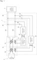
- a transformer 10 constitutes a part of a noise filter device 1 (It is also referred to as active filter).
- the noise filter device 1 is inserted into conductive lines 101 and 102 connecting an AC power source 2 and a noise source device 3.
- the noise filter device 1 includes a normal mode active filter 20 and a common mode active filter 30.
- At least one of the AC power source 2 and the noise source device 3 includes a circuit including an active element.
- the active elements can generate a noise signal.
- the noise source device 3 includes a power factor corrector circuit and a DC/DC converter, or includes a rectifier and an inverter
- at least one of the power factor corrector circuit and the DC/DC converter, or at least one of the rectifier and the inverter includes a circuit including an active element.
- the generated noise signal propagates through the conductive lines 101 and 102 as a normal mode noise signal or a common mode noise signal.
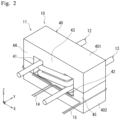
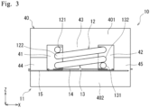
- the transformer 10 includes an iron core 11, a first main winding wire 12, a second main winding wire 13, a first detection winding wire 14, and a second detection winding wire 15.
- the iron core 11, the first main winding wire 12, the second main winding wire 13, the first detection winding wire 14, and the second detection winding wire 15 are insulated from each other.
- the insulation between the iron core 11 and each of the winding wires may be realized, for example, by covering each winding wire with an insulating film, or by covering the iron core 11 with an insulating bobbin or the like.
- the standard of each winding wire is set according to the design, application, and the like of the transformer 10.
- the iron core 11 includes an iron core main body 40 having a substantially rectangular parallelepiped shape.
- the iron core main body 40 includes a first through hole 41 and a second through hole 42 positioned at intervals in a first direction (for example, X direction), and a first leg portion 43 positioned between the first through hole 41 and the second through hole 42.
- the first through hole 41 and the second through hole 42 each penetrate the iron core main body 40 in a second direction (for example, Y direction) intersecting the first direction X.
- the iron core main body 40 includes two magnetic members 401 and 402.
- Each of the members 401 and 402 has a substantially E-shape when viewed along the second direction Y, and includes a second leg portion 44 and a third leg portion 45 in addition to the first leg portion 43.
- the second leg portion 44 is positioned on one side of the first leg portion 43 in the first direction X
- the first through hole 41 is positioned between the second leg portion and the first leg portion 43.
- the third leg portion 45 is positioned on the other (another) side of the first leg portion 43 in the first direction X
- the second through hole 42 is positioned between the third leg portion and the first leg portion 43.
- the first main winding wire 12 is wound around the first leg portion 43, and winding ends 121 and 122 are positioned in the first through hole 41.
- the first main winding wire 12 is wound around the first leg portion 43 so as to start winding from the first through hole 41 and finish winding at the first through hole 41.
- the second main winding wire 13 is wound around the first leg portion 43, and winding ends 131 and 132 are positioned in the second through hole 42.
- the second main winding wire 13 is wound around the first leg portion 43 so as to start winding from the second through hole 42 and finish winding at the second through hole 42.
- Each of the first main winding wire 12 and the second main winding wire 13 is wound around the first leg portion 43 by N.5 turns (N is a natural number). In the present exemplary embodiment, each of the first main winding wire 12 and the second main winding wire 13 is wound around the first leg portion 43 by 1.5 turns.
- the first detection winding wire 14 is wound around the iron core 11 in a state in which the magnetic flux generated by a common mode noise current flowing through the first main winding wire 12 and the second main winding wire 13 is cancelable.
- the first detection winding wire 14 is configured to detect a normal mode noise current flowing through the first main winding wire 12 and the second main winding wire 13.
- the iron core 11, the first main winding wire 12, the second main winding wire 13, and the first detection winding wire 14 are referred to as a normal mode noise current detection unit 51.
- the second detection winding wire 15 is wound around the iron core 11 in a state in which the magnetic flux generated by the normal mode noise current flowing through the first main winding wire 12 and the second main winding wire 13 is cancelable.
- the second detection winding wire 15 is configured to detect the common mode noise current flowing through the first main winding wire 12 and the second main winding wire 13.
- the iron core 11, the first main winding wire 12, the second main winding wire 13, and the second detection winding wire 15 are referred to as a common mode noise current detection unit 52.
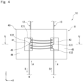
- Fig. 4 illustrates transformer 10 in which each of the first main winding wire 12 and the second main winding wire 13 is wound around the first leg portion 43 by 2.5 turns.
- an arrow A indicates a direction in which the common mode noise current flows through the first main winding wire 12 and the second main winding wire 13
- an arrow B indicates a direction in which the normal mode noise current flows through the first main winding wire 12 and the second main winding wire 13.
- Fig. 5 illustrates an example of a winding method of the first detection winding wire 14
- Fig. 6 illustrates an example of a winding method of the second detection winding wire 15.
- a direction of the magnetic flux due to the normal mode noise current is indicated by a solid line
- a direction of the magnetic flux due to the common mode noise current is indicated by a dotted line.
- An absolute value of a voltage V NM detected by the first detection winding wire 14 is calculated by, for example, the following Formula 1.
- n NM is the number of turns of the first detection winding wire 14 with respect to the iron core 11
- i NM1 is a current value of the normal mode noise current flowing through the first main winding wire 12 and the second main winding wire 13
- R NM is a resistance value of a detection resistor 22 connected to the first detection winding wire 14.
- An absolute value of a voltage V CM detected by the second detection winding wire 15 is calculated by, for example, the following Formula 2.
- n CM is the number of turns of the second detection winding wire 15 with respect to the iron core 11
- i CM1 is a current value of the common mode noise current flowing through the first main winding wire 12 and the second main winding wire 13
- R CM is a resistance value of a detection resistor 31 connected to the second detection winding wire 15.
- n CM 1, for example.
- V CM 1 n CM i CM 1 R CM
- the common mode active filter 30 generates an inverted signal having a polarity opposite to a polarity of the common mode noise signal flowing through the conductive lines 101 and 102.
- the common mode active filter 30 includes the common mode noise current detection unit 52 of the transformer 10, the detection resistor 31, an amplifier circuit 32, and two capacitors 33.
- the second detection winding wire 15 of the transformer 10 is connected to the amplifier circuit 32.
- the detection resistor 31 is positioned between the second detection winding wire 15 and the amplifier circuit 32.
- the amplifier circuit 32 includes, for example, an active element such as an operational amplifier.
- Each capacitor 33 is positioned respectively between the amplifier circuit 23 and the conductive line 101 and between the amplifier circuit 32 and the conductive line 102.
- the transformer 10 and the noise filter device 1 can exhibit the following effects.
- the transformer 10 includes the iron core 11, the first main winding wire 12, the second main winding wire 13, the first detection winding wire 14, and the second detection winding wire 15.
- the iron core 11 includes the iron core main body 40.
- the iron core main body 40 includes the first through hole 41, the second through hole 42, and the first leg portion 43, the first through hole 41 and the second through hole 42 being positioned at intervals in the first direction and penetrating the iron core main body 40 in the second direction, the first leg portion 43 being positioned between the first through hole 41 and the second through hole 42.
- the first main winding wire 12 is wound around the first leg portion 43, and the winding ends 121 and 122 are positioned in the first through hole 41.
- the second main winding wire 13 is wound around the first leg portion 43, and the winding ends 131 and 132 are positioned in the second through hole 42.
- the first detection winding wire 14 is wound around the iron core 11 in a state in which the magnetic flux generated by the common mode noise current flowing through the first main winding wire 12 and the second main winding wire 13 is cancelable.
- the first detection winding wire 14 is configured to detect the normal mode noise current flowing through the first main winding wire 12 and the second main winding wire 13.
- the second detection winding wire 15 is wound around the iron core 11 in a state in which the magnetic flux generated by the normal mode noise current flowing through the first main winding wire 12 and the second main winding wire 13 is cancelable.
- a function as a normal mode choke that filters the normal mode noise current is provided.
- the first detection winding wire 14 and the second detection winding wire 15 are adjusted to obtain desired detection gains as the numbers of turns of the first main winding wire 12 and the second main winding wire 13 increase.
- each of the first main winding wire 12 and the second main winding wire 13 is wound around the first leg portion 43 by 3.5 turns.
- the noise filter device 1 can reduce both the normal mode noise current and the common mode noise current by the transformer 10. As a result, the noise filter device capable of downsizing the power supply circuit can be realized.
- the transformer 10 may be configured as follows.
- the first leg portion 43 may have a gap 61 in a third direction (for example, Z direction) that intersects the first direction X and the second direction Y
- the second leg portion 44 may have a gap 62 in the third direction Z
- the third leg portion 45 may have a gap 63 in the third direction Z.
- the second leg portion 44 includes a pair of second barrel portions 441 and 442 positioned in the third direction Z with the gap 62 therebetween
- the third leg portion 45 includes a pair of third barrel portions 451 and 452 positioned in the third direction Z with the gap 63 therebetween.
- Adjusting inductance is performed, for example, by changing a distance between the barrel portions to change sizes of the gaps in the third direction Z.
- spacers are provided between the pair of first barrel portions 431 and 432, between the pair of second barrel portions 441 and 442, and between the pair of third barrel portions 451 and 452, respectively.
- the size of each of the gaps in the third direction Z can be adjusted by changing a size of the corresponding spacer.
- the spacer is constituted by an insulating sheet, for example.
- the first main winding wire 12 may be wound around the first leg portion 43 and second leg portion 44, and the second main winding wire 13 may be wound around the first leg portion 43 and third leg portion 45.
- inductance with respect to the common mode noise current increases, and a function as a common mode choke that filters the common mode noise current is provided.
- the first detection winding wire 14 and the second detection winding wire 15 are adjusted to obtain desired detection gains as the first main winding wire 12 and the second main winding wire 13 increase.
- Fig. 13 shows the transformer 10 of Fig. 12 with the member 401 removed.
- n 1 is the number of turns obtained by adding the number of turns of the first main winding wire 12 with respect to the second leg portion 44 or the number of turns of the second main winding wire 13 with respect to the third leg portion 45 to the total number of turns of the first main winding wire 12 and the second main winding wire 13 with respect to the first leg portion 43.
- n 0 is the number of turns of the first main winding wire 12 with respect to the second leg portion 44 or the number of turns of the second main winding wire 13 with respect to the third leg portion 45.
- n 0 is 3.
- V NM n 1 n NM i NM 1 R NM
- V CM n o + 1 n CM i CM 1 R CM
- Fig. 14 illustrates another example of the winding method of the first detection winding wire 14
- Fig. 15 illustrates another example of the winding method of the second detection winding wire 15.
- each of the first detection winding wire 14 and the second detection winding wire 15 may be wound around a portion around which the first main winding wire 12 and the second main winding wire 13 are not wound.
- a substantially rectangular plate-shaped plate portion 403 is positioned at each of both ends of the three leg portions in the third direction Z.
- the first detection winding wire 14 and the second detection winding wire 15 are wound around one plate portion 403.
- the plate portion 403 extends along the first direction X, and is connected to one end of the first leg portion 43 in the third direction Z, one end of the second leg portion 44 in the third direction Z, and one end of the third leg portion 45 in the third direction Z.
- the direction of the magnetic flux by the normal mode noise current is indicated by a solid arrow
- the direction of the magnetic flux by the common mode noise current is indicated by a dotted arrow.
- the first detection winding wire 14 may take any configuration in which the first detection winding wire 14 is wound around the iron core 11 in a state in which the magnetic flux generated by the common mode noise current flowing through the first main winding wire 12 and the second main winding wire 13 is cancelable, and the normal mode noise current can be detected.
- the second detection winding wire 15 may take any configuration in which the second detection winding wire 15 is wound around the iron core 11 in a state where the magnetic flux generated by the normal mode noise current flowing through the first main winding wire 12 and the second main winding wire 13 is cancelable, and the common mode noise current can be detected.
- the transformer 10 capable of more reliably downsizing the power supply circuit can be realized.
- the iron core main body 40 may take any configuration in which the first through hole 41, the second through hole 42, and the first leg portion 43 positioned between the first through hole 41 and the second through hole 42 are included.
- the iron core main body 40 may be constituted by a single member.
- the two members 401 and 402 constituting the iron core main body 40 are not limited to the case where both members are substantially E-shaped when viewed along the second direction Y, and one of the members may be substantially I-shaped.
- the transformer 10 may include a bobbin that covers the iron core 11.
- a bobbin that covers the iron core 11.
- each of the first main winding wire 12 and the second main winding wire 13 can be positioned with respect to the first leg portion 43 and held.
- the normal mode active filter 20 may take any configuration with which the normal mode noise current can be reduced.
- the common mode active filter 30 may take any configuration with which the common mode noise current can be reduced.
- a transformer 10 according to a first aspect of the present disclosure includes:
- the transformer 10 according to a second aspect of the present disclosure is configured such that the first leg portion 43 includes a gap 61 in a third direction that intersects the first direction and the second direction.
- the transformer 10 is configured such that the iron core main body 40 includes:
- the transformer 10 according to a fourth aspect of the present disclosure is configured such that
- the transformer 10 according to a fifth aspect of the present disclosure is configured such that each of the first detection winding wire 14 and the second detection winding wire 15 is wound around a portion around which the first main winding wire 12 and the second main winding wire 13 are unwound.
- a noise filter device 1 according to a sixth aspect of the present disclosure includes the transformer 10 according to one of the above aspects.
- the transformer of the present disclosure can be applied to a noise filter device, for example.
- the noise filter device of the present disclosure can be applied to, for example, a power system that operates as a power supply system that receives AC power and outputs DC power of about 2 kW.
Landscapes
- Engineering & Computer Science (AREA)
- Power Engineering (AREA)
- Chemical & Material Sciences (AREA)
- Composite Materials (AREA)
- Filters And Equalizers (AREA)
- Coils Of Transformers For General Uses (AREA)
- Regulation Of General Use Transformers (AREA)
Abstract
Description
- The present disclosure relates to a transformer and a noise filter device.
-
Patent Document 1 discloses a transformer including a tubular bobbin and a coil wound along an outer periphery and an axis of the bobbin. - Patent Document 1:
JP-A-2022-018792 - In general, a noise current detection transformer for an active filter can detect only one of a common mode noise current and a normal mode noise current. Therefore, two transformers are required when both the common mode noise current and the normal mode noise current are reduced, and the power supply circuit may be increased in size.
- An object of the present disclosure is to provide a transformer capable of downsizing a power supply circuit, and a noise filter device including the transformer.
- A transformer according to one aspect of the present disclosure includes:
- an iron core including an iron core main body including a first through hole, a second through hole, and a first leg portion, the first through hole and the second through hole being positioned at intervals in a first direction and each penetrating the iron core main body in a second direction that intersects the first direction, the first leg portion being positioned between the first through hole and the second through hole;
- a first main winding wire wound around the first leg portion and including winding ends positioned in the first through hole;
- a second main winding wire wound around the first leg portion and including winding ends positioned in the second through hole;
- a first detection winding wire wound around the iron core in a state where a magnetic flux generated by a common mode noise current flowing through the first main winding wire and the second main winding wire is cancelable, the first detection winding wire being configured to detect a normal mode noise current flowing through the first main winding wire and the second main winding wire; and
- a second detection winding wire wound around the iron core in a state where a magnetic flux generated by the normal mode noise current is cancelable, the second detection winding wire being configured to detect the common mode noise current.
- A noise filter device according to one aspect of the present disclosure includes the transformer according to the above aspect.
- According to the transformer of the above aspect, it is possible to realize a transformer capable of downsizing a power supply circuit.
- According to the noise filter device of the above aspect, it is possible, by the noise filter device, to realize a noise filter device capable of downsizing the power supply circuit.
-
-
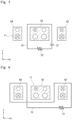
Fig. 1 is a schematic block diagram illustrating a noise filter device including a transformer according to an embodiment of the present disclosure. -
Fig. 2 is a perspective view of the transformer ofFig. 1 . -
Fig. 3 is a front view of the transformer ofFig. 1 . -
Fig. 4 is a schematic front view of the transformer ofFig. 1 . -
Fig. 5 is a first sectional view taken along line V-V ofFig. 4 for explaining how to wind a first detection winding wire. -
Fig. 6 is a first sectional view taken along line V-V ofFig. 4 for explaining how to wind a second detection winding wire. -
Fig. 7 is a second sectional view taken along line V-V ofFig. 4 for explaining how to wind the second detection winding wire. -
Fig. 8 is a third sectional view taken along line V-V ofFig. 4 for explaining how to wind the second detection winding wire. -
Fig. 9 is a perspective view illustrating a first modified example of the transformer ofFig. 1 . -
Fig. 10 is a front view illustrating a second modified example of the transformer ofFig. 1 . -
Fig. 11 is a front view illustrating a third modified example of the transformer ofFig. 1 . -
Fig. 12 is a perspective view illustrating a fourth modified example of the transformer ofFig. 1 . -
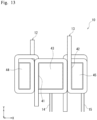
Fig. 13 is a plan view illustrating a state in which a part of an iron core main body of the transformer ofFig. 12 is removed. -
Fig. 14 is a second sectional view taken along line V-V ofFig. 4 for explaining how to wind the first detection winding wire. -
Fig. 15 is a fourth sectional view taken along line V-V ofFig. 4 for explaining how to wind the second detection winding wire. -
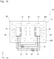
Fig. 16 is a schematic front view for explaining how to wind the first detection winding wire and the second detection winding wire. - Hereinafter, one example of the present disclosure will be described with reference to the accompanying drawings. The following description is merely exemplary in nature and is not intended to limit the present disclosure, its application, or its use. The accompanying drawings are schematic, and ratios of dimensions and the like do not necessarily match actual ones.
- As illustrated in
Fig. 1 , atransformer 10 according to an embodiment of the present disclosure constitutes a part of a noise filter device 1 (It is also referred to as active filter). In the present embodiment, thenoise filter device 1 is inserted intoconductive lines AC power source 2 and anoise source device 3. Thenoise filter device 1 includes a normal modeactive filter 20 and a common modeactive filter 30. - At least one of the
AC power source 2 and thenoise source device 3 includes a circuit including an active element. The active elements can generate a noise signal. For example, when thenoise source device 3 includes a power factor corrector circuit and a DC/DC converter, or includes a rectifier and an inverter, at least one of the power factor corrector circuit and the DC/DC converter, or at least one of the rectifier and the inverter includes a circuit including an active element. The generated noise signal propagates through theconductive lines - As illustrated in
Figs. 2 and3 , thetransformer 10 includes aniron core 11, a firstmain winding wire 12, a secondmain winding wire 13, a firstdetection winding wire 14, and a seconddetection winding wire 15. Theiron core 11, the first main windingwire 12, the second main windingwire 13, the firstdetection winding wire 14, and the seconddetection winding wire 15 are insulated from each other. The insulation between theiron core 11 and each of the winding wires may be realized, for example, by covering each winding wire with an insulating film, or by covering theiron core 11 with an insulating bobbin or the like. The standard of each winding wire is set according to the design, application, and the like of thetransformer 10. - As an example, the
iron core 11 includes an iron coremain body 40 having a substantially rectangular parallelepiped shape. The iron coremain body 40 includes a first throughhole 41 and a second throughhole 42 positioned at intervals in a first direction (for example, X direction), and afirst leg portion 43 positioned between the first throughhole 41 and the second throughhole 42. The first throughhole 41 and the second throughhole 42 each penetrate the iron coremain body 40 in a second direction (for example, Y direction) intersecting the first direction X. - In the present embodiment, the iron core
main body 40 includes twomagnetic members members second leg portion 44 and athird leg portion 45 in addition to thefirst leg portion 43. Thesecond leg portion 44 is positioned on one side of thefirst leg portion 43 in the first direction X, and the first throughhole 41 is positioned between the second leg portion and thefirst leg portion 43. Thethird leg portion 45 is positioned on the other (another) side of thefirst leg portion 43 in the first direction X, and the second throughhole 42 is positioned between the third leg portion and thefirst leg portion 43. - The first main winding
wire 12 is wound around thefirst leg portion 43, andwinding ends hole 41. In other words, the first main windingwire 12 is wound around thefirst leg portion 43 so as to start winding from the first throughhole 41 and finish winding at the first throughhole 41. - The second main winding
wire 13 is wound around thefirst leg portion 43, andwinding ends hole 42. In other words, the second main windingwire 13 is wound around thefirst leg portion 43 so as to start winding from the second throughhole 42 and finish winding at the second throughhole 42. - Each of the first main winding
wire 12 and the second main windingwire 13 is wound around thefirst leg portion 43 by N.5 turns (N is a natural number). In the present exemplary embodiment, each of the first main windingwire 12 and the second main windingwire 13 is wound around thefirst leg portion 43 by 1.5 turns. - The first
detection winding wire 14 is wound around theiron core 11 in a state in which the magnetic flux generated by a common mode noise current flowing through the first main windingwire 12 and the second main windingwire 13 is cancelable. The firstdetection winding wire 14 is configured to detect a normal mode noise current flowing through the first main windingwire 12 and the second main windingwire 13. Hereinafter, theiron core 11, the first main windingwire 12, the second main windingwire 13, and the firstdetection winding wire 14 are referred to as a normal mode noisecurrent detection unit 51. - The second
detection winding wire 15 is wound around theiron core 11 in a state in which the magnetic flux generated by the normal mode noise current flowing through the first main windingwire 12 and the second main windingwire 13 is cancelable. The seconddetection winding wire 15 is configured to detect the common mode noise current flowing through the first main windingwire 12 and the second main windingwire 13. Hereinafter, theiron core 11, the first main windingwire 12, the second main windingwire 13, and the seconddetection winding wire 15 are referred to as a common mode noisecurrent detection unit 52. -
Fig. 4 illustratestransformer 10 in which each of the first main windingwire 12 and the second main windingwire 13 is wound around thefirst leg portion 43 by 2.5 turns. InFig. 4 , an arrow A indicates a direction in which the common mode noise current flows through the first main windingwire 12 and the second main windingwire 13, and an arrow B indicates a direction in which the normal mode noise current flows through the first main windingwire 12 and the second main windingwire 13. -
Fig. 5 illustrates an example of a winding method of the firstdetection winding wire 14, andFig. 6 illustrates an example of a winding method of the seconddetection winding wire 15. InFigs. 5 and 6 , a direction of the magnetic flux due to the normal mode noise current is indicated by a solid line, and a direction of the magnetic flux due to the common mode noise current is indicated by a dotted line. - An absolute value of a voltage VNM detected by the first
detection winding wire 14 is calculated by, for example, the followingFormula 1. In the followingFormula 1, n1 is the total number of turns (=2 × N.5 turns) of the first main windingwire 12 and the second main windingwire 13 with respect to thefirst leg portion 43, nNM is the number of turns of the firstdetection winding wire 14 with respect to theiron core 11, iNM1 is a current value of the normal mode noise current flowing through the first main windingwire 12 and the second main windingwire 13, and RNM is a resistance value of adetection resistor 22 connected to the firstdetection winding wire 14. InFig. 5 , nNM=1, for example,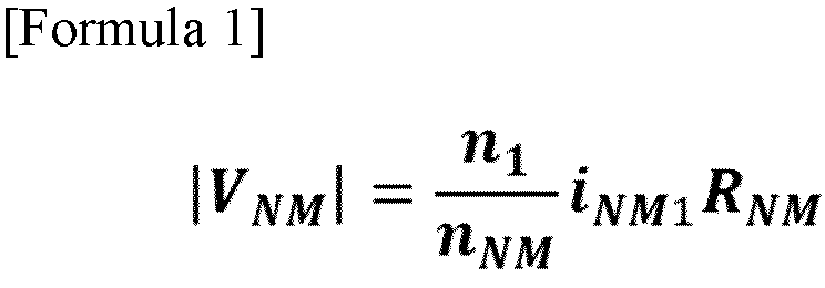
- An absolute value of a voltage VCM detected by the second
detection winding wire 15 is calculated by, for example, the followingFormula 2. In the followingFormula 2, nCM is the number of turns of the seconddetection winding wire 15 with respect to theiron core 11, iCM1 is a current value of the common mode noise current flowing through the first main windingwire 12 and the second main windingwire 13, and RCM is a resistance value of adetection resistor 31 connected to the seconddetection winding wire 15. InFig. 6 , nCM=1, for example. An example of how to wind the seconddetection winding wire 15 when nCM=2 is illustrated inFigs. 7 and 8 .
- The normal mode
active filter 20 generates an inverted signal having a polarity opposite to a polarity of the normal mode noise signal flowing through theconductive lines Fig. 1 , the normal modeactive filter 20 includes the normal mode noisecurrent detection unit 51 of thetransformer 10, afrequency removal filter 21, thedetection resistor 22, anamplifier circuit 23, and acapacitor 24. The firstdetection winding wire 14 of thetransformer 10 is connected to thefrequency removal filter 21. Thefrequency removal filter 21 includes at least one filter circuit. Thedetection resistor 22 is positioned between thefrequency removal filter 21 and theamplifier circuit 23. Theamplifier circuit 23 includes, for example, an active element such as an operational amplifier. Thecapacitor 24 is positioned between theamplifier circuit 23 and theconductive line 101 or between theamplifier circuit 23 and theconductive line 102. - The common mode
active filter 30 generates an inverted signal having a polarity opposite to a polarity of the common mode noise signal flowing through theconductive lines Fig. 1 , the common modeactive filter 30 includes the common mode noisecurrent detection unit 52 of thetransformer 10, thedetection resistor 31, anamplifier circuit 32, and twocapacitors 33. The seconddetection winding wire 15 of thetransformer 10 is connected to theamplifier circuit 32. Thedetection resistor 31 is positioned between the seconddetection winding wire 15 and theamplifier circuit 32. Theamplifier circuit 32 includes, for example, an active element such as an operational amplifier. Eachcapacitor 33 is positioned respectively between theamplifier circuit 23 and theconductive line 101 and between theamplifier circuit 32 and theconductive line 102. - The
transformer 10 and thenoise filter device 1 can exhibit the following effects. - The
transformer 10 includes theiron core 11, the first main windingwire 12, the second main windingwire 13, the firstdetection winding wire 14, and the seconddetection winding wire 15. Theiron core 11 includes the iron coremain body 40. The iron coremain body 40 includes the first throughhole 41, the second throughhole 42, and thefirst leg portion 43, the first throughhole 41 and the second throughhole 42 being positioned at intervals in the first direction and penetrating the iron coremain body 40 in the second direction, thefirst leg portion 43 being positioned between the first throughhole 41 and the second throughhole 42. The first main windingwire 12 is wound around thefirst leg portion 43, and the winding ends 121 and 122 are positioned in the first throughhole 41. The second main windingwire 13 is wound around thefirst leg portion 43, and the winding ends 131 and 132 are positioned in the second throughhole 42. The firstdetection winding wire 14 is wound around theiron core 11 in a state in which the magnetic flux generated by the common mode noise current flowing through the first main windingwire 12 and the second main windingwire 13 is cancelable. The firstdetection winding wire 14 is configured to detect the normal mode noise current flowing through the first main windingwire 12 and the second main windingwire 13. The seconddetection winding wire 15 is wound around theiron core 11 in a state in which the magnetic flux generated by the normal mode noise current flowing through the first main windingwire 12 and the second main windingwire 13 is cancelable. The seconddetection winding wire 15 is configured to detect the common mode noise current flowing through the first main windingwire 12 and the second main windingwire 13. With such a configuration, it is possible to detect both the normal mode noise current and the common mode noise current, and therefore it is not necessary to provide a plurality of transformers even when both the normal mode noise current and the common mode noise current are required to be detected. As a result, thetransformer 10 capable of downsizing the power supply circuit can be realized. - As illustrated in
Fig. 9 , by increasing the numbers of turns of the first main windingwire 12 and the second main windingwire 13 with respect to thefirst leg portion 43, inductance with respect to the normal mode noise current increases, and a function as a normal mode choke that filters the normal mode noise current is provided. The firstdetection winding wire 14 and the seconddetection winding wire 15 are adjusted to obtain desired detection gains as the numbers of turns of the first main windingwire 12 and the second main windingwire 13 increase. InFig. 9 , each of the first main windingwire 12 and the second main windingwire 13 is wound around thefirst leg portion 43 by 3.5 turns. - The
noise filter device 1 can reduce both the normal mode noise current and the common mode noise current by thetransformer 10. As a result, the noise filter device capable of downsizing the power supply circuit can be realized. - The
transformer 10 may be configured as follows. - As illustrated in
Fig. 10 , thefirst leg portion 43 may have agap 61 in a third direction (for example, Z direction) that intersects the first direction X and the second direction Y As illustrated inFig. 11 , thesecond leg portion 44 may have agap 62 in the third direction Z, and thethird leg portion 45 may have agap 63 in the third direction Z. With this configuration, it is possible to adjust inductance with respect to the normal mode noise current or the common mode noise current while magnetic saturation is prevented. InFig. 10 , thefirst leg portion 43 includes a pair offirst barrel portions gap 61 therebetween. InFig. 11 , thesecond leg portion 44 includes a pair ofsecond barrel portions gap 62 therebetween, and thethird leg portion 45 includes a pair ofthird barrel portions gap 63 therebetween. Adjusting inductance is performed, for example, by changing a distance between the barrel portions to change sizes of the gaps in the third direction Z. In thetransformer 10 ofFig. 11 , spacers are provided between the pair offirst barrel portions second barrel portions third barrel portions - As illustrated in
Figs. 12 and13 , the first main windingwire 12 may be wound around thefirst leg portion 43 andsecond leg portion 44, and the second main windingwire 13 may be wound around thefirst leg portion 43 andthird leg portion 45. By increasing the numbers of turns of the first main windingwire 12 and the second main windingwire 13 with respect to thesecond leg portion 44 and thethird leg portion 45, inductance with respect to the common mode noise current increases, and a function as a common mode choke that filters the common mode noise current is provided. The firstdetection winding wire 14 and the seconddetection winding wire 15 are adjusted to obtain desired detection gains as the first main windingwire 12 and the second main windingwire 13 increase. The function as the common mode choke can be used in combination with the function as the normal mode choke obtained by increasing the numbers of turns of the first main windingwire 12 and the second main windingwire 13 with respect to the first leg portion 43 (seeFig. 9 ).Fig. 13 shows thetransformer 10 ofFig. 12 with themember 401 removed. - In the
transformer 10 ofFigs. 12 and13 , the absolute value of the voltage VNM detected by the firstdetection winding wire 14 is calculated by, for example, the followingFormula 3, and the absolute value of the voltage VCM detected by the seconddetection winding wire 15 is calculated by, for example, the following Formula 4. In the followingFormula 3, n1 is the number of turns obtained by adding the number of turns of the first main windingwire 12 with respect to thesecond leg portion 44 or the number of turns of the second main windingwire 13 with respect to thethird leg portion 45 to the total number of turns of the first main windingwire 12 and the second main windingwire 13 with respect to thefirst leg portion 43. InFigs. 12 and13 , n1 is 2×1.5+3=6. In the following Formula 4, n0 is the number of turns of the first main windingwire 12 with respect to thesecond leg portion 44 or the number of turns of the second main windingwire 13 with respect to thethird leg portion 45. InFigs. 12 and13 , n0 is 3.

-
Fig. 14 illustrates another example of the winding method of the firstdetection winding wire 14, andFig. 15 illustrates another example of the winding method of the seconddetection winding wire 15. As illustrated inFig. 16 , each of the firstdetection winding wire 14 and the seconddetection winding wire 15 may be wound around a portion around which the first main windingwire 12 and the second main windingwire 13 are not wound. In thetransformer 10 ofFig. 16 , a substantially rectangular plate-shapedplate portion 403 is positioned at each of both ends of the three leg portions in the third direction Z. The firstdetection winding wire 14 and the seconddetection winding wire 15 are wound around oneplate portion 403. Theplate portion 403 extends along the first direction X, and is connected to one end of thefirst leg portion 43 in the third direction Z, one end of thesecond leg portion 44 in the third direction Z, and one end of thethird leg portion 45 in the third direction Z. InFig. 16 , the direction of the magnetic flux by the normal mode noise current is indicated by a solid arrow, and the direction of the magnetic flux by the common mode noise current is indicated by a dotted arrow. As described above, the firstdetection winding wire 14 may take any configuration in which the firstdetection winding wire 14 is wound around theiron core 11 in a state in which the magnetic flux generated by the common mode noise current flowing through the first main windingwire 12 and the second main windingwire 13 is cancelable, and the normal mode noise current can be detected. Further, the seconddetection winding wire 15 may take any configuration in which the seconddetection winding wire 15 is wound around theiron core 11 in a state where the magnetic flux generated by the normal mode noise current flowing through the first main windingwire 12 and the second main windingwire 13 is cancelable, and the common mode noise current can be detected. As a result, it is possible to increase a degree of freedom in designing thetransformer 10, and therefore thetransformer 10 capable of more reliably downsizing the power supply circuit can be realized. - The iron core
main body 40 may take any configuration in which the first throughhole 41, the second throughhole 42, and thefirst leg portion 43 positioned between the first throughhole 41 and the second throughhole 42 are included. For example, the iron coremain body 40 may be constituted by a single member. The twomembers main body 40 are not limited to the case where both members are substantially E-shaped when viewed along the second direction Y, and one of the members may be substantially I-shaped. - The
transformer 10 may include a bobbin that covers theiron core 11. By including the bobbin, for example, each of the first main windingwire 12 and the second main windingwire 13 can be positioned with respect to thefirst leg portion 43 and held. - The normal mode
active filter 20 may take any configuration with which the normal mode noise current can be reduced. Similarly, the common modeactive filter 30 may take any configuration with which the common mode noise current can be reduced. - Various embodiments of the present disclosure have been described above in detail with reference to the drawings, and finally, various aspects of the present disclosure will be described. In the following description, as an example, reference numerals are also added.
- A
transformer 10 according to a first aspect of the present disclosure includes: - an
iron core 11 including an iron coremain body 40 including a first throughhole 41, a second throughhole 42, and afirst leg portion 43, the first throughhole 41 and the second throughhole 42 being positioned at intervals in a first direction and each penetrating the iron coremain body 40 in a second direction that intersects the first direction, thefirst leg portion 43 being positioned between the first throughhole 41 and the second throughhole 42; - a first main winding
wire 12 wound around thefirst leg portion 43 and including winding ends 121 and 122 positioned in the first throughhole 41; - a second main winding
wire 13 wound around thefirst leg portion 43 and including winding ends 131 and 132 positioned in the second throughhole 42; - a first
detection winding wire 14 wound around theiron core 11 in a state where a magnetic flux generated by a common mode noise current flowing through the first main windingwire 12 and the second main windingwire 13 is cancelable, the firstdetection winding wire 14 being configured to detect a normal mode noise current flowing through the first main windingwire 12 and the second main windingwire 13; and - a second
detection winding wire 15 wound around theiron core 11 in a state where a magnetic flux generated by the normal mode noise current is cancelable, the seconddetection winding wire 15 being configured to detect the common mode noise current. - The
transformer 10 according to a second aspect of the present disclosure is configured such that
thefirst leg portion 43 includes agap 61 in a third direction that intersects the first direction and the second direction. - The
transformer 10 according to a third aspect of the present disclosure is configured such that
the iron coremain body 40 includes: - a
second leg portion 44 positioned on one side of thefirst leg portion 43 in the first direction, the first throughhole 41 being positioned between thefirst leg portion 43 and thesecond leg portion 44; and - a
third leg portion 45 positioned on another side of thefirst leg portion 43 in the first direction, the second throughhole 42 being positioned between thefirst leg portion 43 and thethird leg portion 45, and - the
second leg portion 44 and thethird leg portion 45 each include agap - The
transformer 10 according to a fourth aspect of the present disclosure is configured such that - the first main winding
wire 12 is wound around each of thefirst leg portion 43 and thesecond leg portion 44, and - the second main winding
wire 13 is wound around each of thefirst leg portion 43 and thethird leg portion 45. - The
transformer 10 according to a fifth aspect of the present disclosure is configured such that
each of the firstdetection winding wire 14 and the seconddetection winding wire 15 is wound around a portion around which the first main windingwire 12 and the second main windingwire 13 are unwound. - A
noise filter device 1 according to a sixth aspect of the present disclosure includes thetransformer 10 according to one of the above aspects. - By appropriately combining arbitrary embodiments or modified examples among the various embodiments or modified examples, it is possible to achieve the effects of the corresponding embodiments or modified examples. In addition, a combination of the embodiments, a combination of the examples, or a combination of the embodiment and the example are possible, and a combination of features in the different embodiments or examples are also possible.
- Although the present disclosure has been fully described in connection with preferred embodiments with reference to the accompanying drawings, various changes and modifications will be apparent to those skilled in the art. It is understood that such changes and modifications are included within the scope of the present disclosure as set forth in the appended claims.
- The transformer of the present disclosure can be applied to a noise filter device, for example.
- The noise filter device of the present disclosure can be applied to, for example, a power system that operates as a power supply system that receives AC power and outputs DC power of about 2 kW.
-
- 1
- noise filter device
- 2
- AC power source
- 3
- noise source device
- 10
- transformer
- 11
- iron core
- 12
- first main winding wire
- 13
- second main winding wire
- 14
- first detection winding wire
- 15
- second detection winding wire
- 20
- normal mode active filter
- 21
- frequency removal filter
- 22
- detection resistor
- 23
- amplifier circuit
- 24
- capacitor
- 30
- common mode active filter
- 31
- detection resistor
- 32
- amplifier circuit
- 33
- capacitor
- 40
- iron core main body
- 401, 402
- member
- 403
- plate portion
- 41
- first through hole
- 42
- second through hole
- 43
- first leg portion
- 431, 432
- first barrel portion
- 44
- second leg portion
- 441, 442
- second barrel portion
- 45
- third leg portion
- 451, 452
- third barrel portion
- 51
- normal mode noise current detection unit
- 52
- common mode noise current detection unit
- 61, 62, 63
- gap
- 101, 102
- conductive line
Claims (6)
- A transformer, comprising:an iron core including an iron core main body including a first through hole, a second through hole, and a first leg portion, the first through hole and the second through hole being positioned at intervals in a first direction and each penetrating the iron core main body in a second direction that intersects the first direction, the first leg portion being positioned between the first through hole and the second through hole;a first main winding wire wound around the first leg portion and including winding ends positioned in the first through hole;a second main winding wire wound around the first leg portion and including winding ends positioned in the second through hole;a first detection winding wire wound around the iron core in a state where a magnetic flux generated by a common mode noise current flowing through the first main winding wire and the second main winding wire is cancelable, the first detection winding wire being configured to detect a normal mode noise current flowing through the first main winding wire and the second main winding wire; anda second detection winding wire wound around the iron core in a state where a magnetic flux generated by the normal mode noise current is cancelable, the second detection winding wire being configured to detect the common mode noise current.
- The transformer according to claim 1, wherein
the first leg portion includes a gap in a third direction that intersects the first direction and the second direction. - The transformer according to claim 1 or 2, wherein
the iron core main body includes:a second leg portion positioned on one side of the first leg portion in the first direction, the first through hole being positioned between the first leg portion and the second leg portion; anda third leg portion positioned on another side of the first leg portion in the first direction, the second through hole being positioned between the first leg portion and the third leg portion, andthe second leg portion and the third leg portion each include a gap in a third direction that intersects the first direction and the second direction. - The transformer according to claim 3, whereinthe first main winding wire is wound around each of the first leg portion and the second leg portion, andthe second main winding wire is wound around each of the first leg portion and the third leg portion.
- The transformer according to any one of claims 1 to 4, wherein
each of the first detection winding wire and the second detection winding wire is wound around a portion around which the first main winding wire and the second main winding wire are unwound. - A noise filter device, comprising:
the transformer according to any one of claims 1 to 5.
Applications Claiming Priority (2)
| Application Number | Priority Date | Filing Date | Title |
|---|---|---|---|
| JP2022033794A JP7740066B2 (en) | 2022-03-04 | 2022-03-04 | Transformers and noise filtering devices |
| PCT/JP2023/003603 WO2023166913A1 (en) | 2022-03-04 | 2023-02-03 | Transformer and noise filter device |
Publications (2)
| Publication Number | Publication Date |
|---|---|
| EP4489041A1 true EP4489041A1 (en) | 2025-01-08 |
| EP4489041A4 EP4489041A4 (en) | 2026-03-18 |
Family
ID=87883307
Family Applications (1)
| Application Number | Title | Priority Date | Filing Date |
|---|---|---|---|
| EP23763175.9A Pending EP4489041A4 (en) | 2022-03-04 | 2023-02-03 | TRANSFORMER AND NOISE FILTER DEVICE |
Country Status (5)
| Country | Link |
|---|---|
| US (1) | US20250174392A1 (en) |
| EP (1) | EP4489041A4 (en) |
| JP (1) | JP7740066B2 (en) |
| CN (1) | CN118805230A (en) |
| WO (1) | WO2023166913A1 (en) |
Family Cites Families (6)
| Publication number | Priority date | Publication date | Assignee | Title |
|---|---|---|---|---|
| JP3509436B2 (en) * | 1996-12-02 | 2004-03-22 | 松下電器産業株式会社 | Noise filter |
| JP2004274161A (en) * | 2003-03-05 | 2004-09-30 | Tdk Corp | Noise suppression circuit |
| JP4873534B2 (en) * | 2005-12-09 | 2012-02-08 | Necトーキン株式会社 | Inductor |
| JP5790700B2 (en) * | 2013-04-15 | 2015-10-07 | 株式会社デンソー | Filter parts |
| US11322298B2 (en) * | 2017-09-15 | 2022-05-03 | University Of Florida Research Foundation, Incorporated | Integrated common mode and differential mode inductors with low near magnetic field emission |
| JP7506547B2 (en) | 2020-07-16 | 2024-06-26 | 株式会社東郷製作所 | Trance |
-
2022
- 2022-03-04 JP JP2022033794A patent/JP7740066B2/en active Active
-
2023
- 2023-02-03 EP EP23763175.9A patent/EP4489041A4/en active Pending
- 2023-02-03 CN CN202380024790.4A patent/CN118805230A/en active Pending
- 2023-02-03 WO PCT/JP2023/003603 patent/WO2023166913A1/en not_active Ceased
- 2023-02-03 US US18/843,459 patent/US20250174392A1/en active Pending
Also Published As
| Publication number | Publication date |
|---|---|
| US20250174392A1 (en) | 2025-05-29 |
| JP2023129038A (en) | 2023-09-14 |
| JP7740066B2 (en) | 2025-09-17 |
| WO2023166913A1 (en) | 2023-09-07 |
| EP4489041A4 (en) | 2026-03-18 |
| CN118805230A (en) | 2024-10-18 |
Similar Documents
| Publication | Publication Date | Title |
|---|---|---|
| US4206434A (en) | Regulating transformer with magnetic shunt | |
| US10283262B2 (en) | Enhanced common mode current reduction in three-phase inductors, transformers, and motor drive systems | |
| EP0579962A1 (en) | Choke coil | |
| EP2677526A1 (en) | Integrated magnetics for soft switching converter | |
| US20040233683A1 (en) | Method and apparatus for substantially reducing electrical earth displacement current flow generated by wound components without requiring additional windings | |
| DE102013106099A1 (en) | Flow sensor assembly | |
| EP3008474A1 (en) | Current sensor arrangement with measuring coils | |
| US7535125B2 (en) | Single-phase filter for reducing harmonics | |
| US20250174392A1 (en) | Transformer and noise filter device | |
| EP2631920A9 (en) | Integrated common mode and differential mode choke | |
| JP2010093153A (en) | Trance | |
| US12266458B2 (en) | Common mode choke | |
| EP1929489B1 (en) | A foil winding pulse transformer | |
| JPH0745451A (en) | Switching transformer | |
| US5886507A (en) | Controlled ferroresonant transformer | |
| JP2008159817A (en) | Reactor and power supply device using it | |
| JPS58212110A (en) | Electromagnetic induction apparatus | |
| JPH10241972A (en) | High-voltage transformer for lighting discharge lamps | |
| US3745499A (en) | Voltage stabilizing transformer | |
| JP2011096744A (en) | Inductor | |
| JPH1027723A (en) | Coil parts | |
| JP3357684B2 (en) | Saturable reactor | |
| US20250349457A1 (en) | Magnetic Device | |
| CN121748141A (en) | EMI filter | |
| JPH0883722A (en) | Foil winding transformer |
Legal Events
| Date | Code | Title | Description |
|---|---|---|---|
| STAA | Information on the status of an ep patent application or granted ep patent |
Free format text: STATUS: THE INTERNATIONAL PUBLICATION HAS BEEN MADE |
|
| PUAI | Public reference made under article 153(3) epc to a published international application that has entered the european phase |
Free format text: ORIGINAL CODE: 0009012 |
|
| STAA | Information on the status of an ep patent application or granted ep patent |
Free format text: STATUS: REQUEST FOR EXAMINATION WAS MADE |
|
| 17P | Request for examination filed |
Effective date: 20240822 |
|
| AK | Designated contracting states |
Kind code of ref document: A1 Designated state(s): AL AT BE BG CH CY CZ DE DK EE ES FI FR GB GR HR HU IE IS IT LI LT LU LV MC ME MK MT NL NO PL PT RO RS SE SI SK SM TR |
|
| DAV | Request for validation of the european patent (deleted) | ||
| DAX | Request for extension of the european patent (deleted) | ||
| REG | Reference to a national code |
Ref country code: DE Ref legal event code: R079 Free format text: PREVIOUS MAIN CLASS: H01F0030100000 Ipc: H01F0003140000 |
|
| A4 | Supplementary search report drawn up and despatched |
Effective date: 20260213 |
|
| RIC1 | Information provided on ipc code assigned before grant |
Ipc: H01F 3/14 20060101AFI20260209BHEP Ipc: H01F 19/00 20060101ALI20260209BHEP Ipc: H01F 27/38 20060101ALI20260209BHEP Ipc: H01F 27/40 20060101ALI20260209BHEP Ipc: H03H 7/09 20060101ALI20260209BHEP Ipc: H03H 7/42 20060101ALI20260209BHEP |