EP4488800A1 - Human pose estimation - Google Patents
Human pose estimation Download PDFInfo
- Publication number
- EP4488800A1 EP4488800A1 EP23183665.1A EP23183665A EP4488800A1 EP 4488800 A1 EP4488800 A1 EP 4488800A1 EP 23183665 A EP23183665 A EP 23183665A EP 4488800 A1 EP4488800 A1 EP 4488800A1
- Authority
- EP
- European Patent Office
- Prior art keywords
- operator
- estimate
- pose
- clothing
- item
- Prior art date
- Legal status (The legal status is an assumption and is not a legal conclusion. Google has not performed a legal analysis and makes no representation as to the accuracy of the status listed.)
- Pending
Links
Images




Classifications
-
- G—PHYSICS
- G06—COMPUTING OR CALCULATING; COUNTING
- G06F—ELECTRIC DIGITAL DATA PROCESSING
- G06F3/00—Input arrangements for transferring data to be processed into a form capable of being handled by the computer; Output arrangements for transferring data from processing unit to output unit, e.g. interface arrangements
- G06F3/01—Input arrangements or combined input and output arrangements for interaction between user and computer
- G06F3/011—Arrangements for interaction with the human body, e.g. for user immersion in virtual reality
-
- A—HUMAN NECESSITIES
- A61—MEDICAL OR VETERINARY SCIENCE; HYGIENE
- A61B—DIAGNOSIS; SURGERY; IDENTIFICATION
- A61B5/00—Measuring for diagnostic purposes; Identification of persons
- A61B5/68—Arrangements of detecting, measuring or recording means, e.g. sensors, in relation to patient
- A61B5/6801—Arrangements of detecting, measuring or recording means, e.g. sensors, in relation to patient specially adapted to be attached to or worn on the body surface
- A61B5/6802—Sensor mounted on worn items
- A61B5/6804—Garments; Clothes
Definitions
- the present disclosure relates to a system, computer-implemented method, non-transitory computer-readable storage medium, and computer for human pose estimation.
- CN107744393A proposes a gravity acceleration sensor-based wearable for use in a posture monitoring system.
- the gravity acceleration sensors are mounted to the back of the clothes, and changes to the operator's posture is sensed together with respiratory parameters.
- embodiments of the present invention provide a system for performing human pose estimation, the system comprising:
- the system may include any one, or any combination insofar as they are compatible, of the optional features set out with reference to the first aspect.
- the sensor(s) attached to the item of clothing may be inertial measurement units (IMUs).
- IMUs inertial measurement units
- the first estimate of the pose and/or the second estimate of the pose may define the position and/or orientation of one or more joints of the operator.
- the first and/or second estimate of the pose may, but does not necessarily have to be, an entire pose of the operator, e.g., it may include only a partial pose of the operator.
- the first and/or second estimate of the pose may only define the position and/or orientation of a single joint of the operator (e.g., wrist joint).
- distance it may be meant an angular distance, for example a first vector describing the projection of a portion of the body according to the first estimate as compared to second vector describing the projection of the same portion of the body according to the second estimate.
- the optical sensor may be a camera.
- the camera may be a security camera, for example fixed to a portion of infrastructure.
- the camera may be a wearable head-mounted camera.
- the processor may be configured to detect the operator's hand(s) using data from the wearable head-mounted camera and utilise the detected position of the operator's hand(s) in the second estimate of the pose of the operator.
- the processor may be configured to identify when the operator is within a capture area of the optical sensor, and to trigger the optical sensor to capture the second estimate of the pose when it has been identified that the operator is within the capture area.
- the camera When the camera is a wearable head-mounted camera, it may be worn by a second operator different to the operator wearing the item of clothing (and so detection may occur when this second operator directs the camera to the operator wearing the item of clothing).
- the processor may be configured to alert the operator when it is determined that the operator is wearing the item of clothing incorrectly.
- the first estimate and second estimate may each respectively include data defining a position and/or orientation of one or more joints of the operator's body. Calculating the difference may include calculating a distance between a joint a defined by the first estimate and the same joint as defined by the second estimate.
- the processor may be configured to determine that the operator is wearing the item of clothing incorrectly by determining a similarity between the calculated distance for each joint and a stored distance in an error database, and the processor may determine that the operator is wearing the item of clothing incorrectly when the determined similarity is greater than a threshold.
- the system may further comprise an augmented reality device, and the processor may be configured, in response to determining that the operator is wearing the item of clothing incorrectly, to provide guidance to the operator via the augmented reality device.
- the augmented reality device may be, for example, a virtual reality headset, augmented reality headset, or mixed reality headset.
- the processor may be configured, in response to determining that the operator is wearing the item of clothing incorrectly, to detect a dangerous action being performed by the operator.
- embodiments of the present invention provide a computer-implemented method for performing human pose estimation, the method comprising steps of:
- embodiments of the present invention provide a computer comprising a processor and memory, the memory containing machine-executable instructions which, when executed on the processor, cause the processor to:
- the computer may include an optical pose estimation module, motion capturing module, and error detection module.
- embodiments of the present invention provide a non-transitory computer-readable storage medium containing machine-executable instructions which, when executed on a processor, cause the processor to perform the method of the second aspect.
- the invention includes the combination of the aspects and preferred features described except where such a combination is clearly impermissible or expressly avoided.
- Figure 1 shows a system 100, which includes a processor 101 connected to a camera 102 and one or more IMU sensors attached to an item of clothing 104.
- the processor contains or operates an optical pose estimation module 106 and a motion capturing module 108, both of which may be implemented as pieces of software.
- the processor is a distributed processor (e.g., comprises one or more processors connected together).
- the motion capturing module 108 receives data from one or more IMU sensors 104 and utilises this in obtaining a first estimate of a pose of an operator wearing the item of clothing.
- the motion capturing module 108 uses methods known per se in the art (e.g. Inertial-Based Human Motion Capture: A Technology Summary of Current Processing Methodologies for Spatiotemporal and Kinematic Measures, Hindle et al., Appl. Bionics Biomech. 2021; 6628320 ).
- One or more signal from the one or more sensors which are attached to a body of the person are received by the motion capturing module 108. Based on these signals, skeletal data is created.
- the IMU sensors may include, for example, at least one accelerometer, at least one gyroscope, and at least one magnetometer.
- the skeletal data may be created by using the sensor signals to model a kinematic chain, which can describe the motion constraints of an articulated rigid body such as the human skeleton.
- the concept underpinning a kinematic chain is that the motion of a body segment is given by the motion of the previous body segment in the chain and an angular rotation around a joint axis.
- the kinematic chain can therefore be defined with a six degrees of freedom root joint representing the global rigid body motion and a set of one degree of freedom revolute joints describing the angular motion of the limbs.
- the created skeletal data may include position and/or orientation of parts of the person's body.
- the optical pose estimation module receives data from the camera and utilises this in obtaining a second estimate of a pose of the operator wearing the item of clothing.
- the optical pose estimation module can use methods known per se in the art (see, e.g., the OpenPose library from Viso Suite).
- the first and second estimated poses are provided to an error detecting module 110, which uses the first and second estimated poses together with a database 112 to identify if the operator is wearing the item of clothing incorrectly. It also determines a type of wrong wearing, for example that the sleeve of the item of clothing is flipped or twisted around the forearm.
- Figs. 2A and 2B illustrate a first 200 and second 210estimated pose.
- Each pose is formed of joints 202 of the body connected by links 204, for example hand joint 206a,b.
- the first 200 estimated pose is obtained from the IMU sensor data, but as the right sleeve of the item of clothing was flipped it shows that a hand joint 206a of the operator is located above the elbow joint 202 of the operator.
- the hand joint 206b in the second 210 estimated pose is located below the elbow joint 202 of the operator, illustrating a difference between the first and second estimated poses.
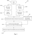
- FIG. 3 is a flow chart illustrating a method 300.
- the method begins with step S302, and proceeds down two parallel paths.
- step S304 IMU sensor data is received from the one or more IMU sensors attached to the item of clothing worn by the operator.
- this IMU data is used in a motion capture step S306 to derive a first estimate of the pose of the operator.
- step S308 video data (e.g., RGB data) is received from an optical sensor.
- RGB data is indicative of a second estimate of a pose of the operator by virtue of capturing an image of the operator.
- step S310 an optical pose estimation step is performed using the received RGB data to derive a second estimate of the pose of the operator.
- step S312 joint distances are calculated between the two poses. That is, a distance is calculated between a joint as defined in the first estimate and the same joint as defined in the second estimate. For example, the distance between the position of the operator's left elbow as defined in the first estimate and the position of the operator's left elbow as defined in the second estimate is calculated.
- step S314 reference is made to a database 320 to find the most similar joints distance in the database 320.
- the database contains a table where distances between joints is related to an incorrect wearing type. An example of such a table is shown in Figure 4 .
- the type e.g., right hand error
- the method moves to step S316, where an error type of wearing the item of clothing is decided if a given similarity is over a pre-set threshold.
- FIG. 5 shows a variant system 200.
- system 200 includes features in common with system 100 in Figure 1 , like features are indicated by like reference numerals.
- system 200 includes a worker detection module 20.
- the worker detection module may be configured to utilise the data received from camera 102 to trigger the optical pose estimation module 106 when it detects the presence of the worker wearing the item of clothing with the IMU sensor(s) attached.
- the worker detection module 202 may be utilised to identify which of the people is the one wearing the item of clothing with the IMU sensors attached. For example, all people within the image captured by the camera may be optically tracked and then one who's movements correspond to the motion captured by the IMU is identified.
- the clothing may include an optical marker such that the system can identify the user wearing the item of clothing through detecting this optical marker.
- Figure 6 shows a method 600 of using the variant system of Figure 5 . Where it shares features with the method 300 shown in Figure 3 , like features are indicated by like reference numerals.
- method 600 includes an additional step S402 located between steps S308 and S310.
- the RGB data is received in step S308, and then a person detection step is performed in S402.
- the person detecting step the operator wearing the item of clothing may be detected from the captured RGB data received from the camera 308. This may trigger the motion capturing step S306 to derive the first estimate of the pose of the operator.
- the person detection step S402 may also include identifying which person, of multiple people within view of the camera, is wearing the item of clothing with the IMU sensor(s) attached thereto.
- Figure 7 shows a variant system 700.
- the camera in system 700 is a head-mounted camera (in Figures 1 and 5 , the camera is a static camera for example a security camera).
- the system 700 further includes a hand detection module 704, which utilises the data captured from the head mounted camera 702 to determine the second estimate of the pose of the operator (e.g., the position of the operator's hand(s)).
- a variant error detecting module 706 utilises the database 112 together with the first estimate from motion capturing module 108 and the second estimate from the hand detection module 704 to determine if the operator is wearing the item of clothing incorrectly.
- FIG 8 shows a method 800 of using the variant system of Figure 7 .
- the method 700 shares features with the methods 300 and 600 shown in Figures 3 and 6 , like features are indicated by like reference numerals.
- the method differs in that step S308 is followed by step S802 in which a hand detection step is performed.
- the hand detection step utilises the RGB data received from the head mounted camera, and when the operator's hand(s) are detected from that data the motion capturing step S306 can be triggered.
- a hand position estimation step S804 is performed, using the RGB data, to derive the second estimate of the operator's pose. The distance between the position of the operator's hand(s) as defined in the first and second estimates respectively is then calculated in step S806.
- step S808 reference is made to a database 320.
- the database contains a table where distances between joints is related to an incorrect wearing type. An example of such a table is shown in Figure 4 .
- the method moves to step S810, where an error type of wearing the item of clothing is decided if a given similarity is over a pre-set threshold.
- Figure 9 shows the use of hand position for identifying incorrect wearing.
- the step S314 in Figure 3 is modified so that the distance is calculated only for the hands as detected by the IMU and optically tracked by the head mounted camera.
- FIG 10 shows a variant system 900.
- the system 900 differs from system 100 in that it further includes an operator user interface module 902 (e.g., headphones, display, speakers, or haptic feedback device).
- the operator user interface module 902 includes an alert module 903, which receives an indication from processor 101 that the operator is incorrectly wearing the item of clothing. In response, the alert module 903 notifies the operator. The notification may notify that the item of clothing is being incorrectly worn with or without an indication as to the type of incorrect wearing (e.g., twisted sleeve).
- FIG 11 shows a variant system 1100. Where the system 1100 shares features with system 100 in Figure 1 , like features are indicated by like reference numerals.
- the system 1100 differs in that processor 1101 also includes a dangerous action detection module 1103 which utilises a dangerous actions database 1102 to detect a dangerous human action (e.g., one which may lead to a dangerous situation for the person carrying out the working process or other persons in the vicinity).
- a dangerous action e.g., one which may lead to a dangerous situation for the person carrying out the working process or other persons in the vicinity.
- Figure 12 shows a variant system 1200. Where the system 1200 shares features with system 100, like features are indicated by like reference numerals.
- the system 1200 differs in that the processor 1201 also includes an action detection module 1202 which utilises data from the error detecting module 110, a 3D model 1203, and a predefined action database 1204 to detect an action being or about to be performed by the operator.
- Guidance module 1205 receives data from the action detection module 1202, and outputs guidance to an AR device 1206 worn by the operator. For example, the system may detect a dangerous action of the person by comparing the person's estimated pose with the plurality of dangerous actions stored in the dangerous action database.
- a warning signal can be generated by a warning device can be outputted via an output device.
- the warning signal may be a visual, audible, and/or haptic warning signal that alerts the operator that their current action may lead to a dangerous situation.
- the guidance process may include the predefined action database storing a plurality of predetermined working actions.
- a working action in this sense may be a human action related to a working process, such as assembling, drilling, jiggering, etc.
- the guidance database may include information for supporting, improving, and/or optimizing a working process as well as information for avoiding a dangerous situation throughout the working process.
- the AR device may be, for example, a pair of glasses, a smartphone, a tablet, or any other device suitable for providing an augmented reality interface.
- the system may detect a working action of the person by comparing the person's estimated poses with a plurality of working actions stored on the working action database.
- Guidance information may be determined related to the detected working action based on the plurality of guidance information stored in the guidance database. Subsequently, the system may output the determined guidance information to the augmented reality device work and/or carried by the person via the output device (not shown).
- a computer system includes the hardware, software and data storage devices for embodying a system or carrying out a method according to the above-described embodiments.
- a computer system may comprise a central processing unit (CPU), input means, output means and data storage.
- the computer system may have a monitor to provide a visual output display.
- the data storage may comprise RAM, disk drives or other computer readable media.
- the computer system may include a plurality of computing devices connected by a network and able to communicate with each other over that network.
- the methods of the above embodiments may be provided as computer programs or as computer program products or computer readable media carrying a computer program which is arranged, when run on a computer, to perform the method(s) described above.
- computer readable media includes, without limitation, any non-transitory medium or media which can be read and accessed directly by a computer or computer system.
- the media can include, but are not limited to, magnetic storage media such as floppy discs, hard disc storage media and magnetic tape; optical storage media such as optical discs or CD-OMs; electrical storage media such as memory, including RAM, ROM and flash memory; and hybrids and combinations of the above such as magnetic/optical storage media.
Landscapes
- Engineering & Computer Science (AREA)
- Health & Medical Sciences (AREA)
- Life Sciences & Earth Sciences (AREA)
- General Engineering & Computer Science (AREA)
- Physics & Mathematics (AREA)
- Theoretical Computer Science (AREA)
- General Health & Medical Sciences (AREA)
- Public Health (AREA)
- Medical Informatics (AREA)
- Molecular Biology (AREA)
- Surgery (AREA)
- Animal Behavior & Ethology (AREA)
- Pathology (AREA)
- Heart & Thoracic Surgery (AREA)
- Veterinary Medicine (AREA)
- Biomedical Technology (AREA)
- Human Computer Interaction (AREA)
- General Physics & Mathematics (AREA)
- Biophysics (AREA)
- User Interface Of Digital Computer (AREA)
Abstract
A system for performing human pose estimation. The system comprises: an item of clothing including one or more sensors attached thereto, the or each sensor being configured to obtain data indicative of a first estimate of a pose of an operator wearing the clothing; an optical sensor, configured to obtain data indicative of a second estimate of the pose of the operator; a processor, configured to: calculate a difference between the first estimate of the pose and the second estimate of the pose; determine, based on the calculated difference, whether the operator is wearing the item of clothing incorrectly.
Description
- The present disclosure relates to a system, computer-implemented method, non-transitory computer-readable storage medium, and computer for human pose estimation.
- In managing health and safety of workers, active monitoring technology has been deployed so as to know the current condition of a worker. Motion capture, using smart clothing where inertial measurement unit (IMU) sensors are attached to normal clothing, is emerging as a promising technology as it does not disturb the workers and can provide continuous results. However, there can be large errors in the data collected during motion capture if the item of clothing is incorrectly worn e.g., the sleeve is twisted.
- It would be advantageous then to know whether the worker is correctly wearing the item of clothing.
-
CN107744393A proposes a gravity acceleration sensor-based wearable for use in a posture monitoring system. The gravity acceleration sensors are mounted to the back of the clothes, and changes to the operator's posture is sensed together with respiratory parameters. - The present disclosure was arrived at in light of the above considerations.
- Accordingly, in a first aspect, embodiments of the present invention provide a system for performing human pose estimation, the system comprising:
- an item of clothing including one or more sensors attached thereto, the or each sensor being configured to obtain data indicative of a first estimate of a pose of an operator wearing the clothing;
- an optical sensor, configured to obtain data indicative of a second estimate of the pose of the operator; and
- a processor, configured to:
- calculate a difference between the first estimate of the pose and the second estimate of the pose, and
- determine, based on the calculated difference, whether the operator is wearing the item of clothing incorrectly.
- Such a system and quickly and accurately estimate a pose of the operator and can mitigate against errors which would arise from the operator wearing the item of clothing incorrectly.
- The system may include any one, or any combination insofar as they are compatible, of the optional features set out with reference to the first aspect.
- The sensor(s) attached to the item of clothing may be inertial measurement units (IMUs).
- The first estimate of the pose and/or the second estimate of the pose may define the position and/or orientation of one or more joints of the operator. For the avoidance of doubt, the first and/or second estimate of the pose may, but does not necessarily have to be, an entire pose of the operator, e.g., it may include only a partial pose of the operator. For example, the first and/or second estimate of the pose may only define the position and/or orientation of a single joint of the operator (e.g., wrist joint). By distance it may be meant an angular distance, for example a first vector describing the projection of a portion of the body according to the first estimate as compared to second vector describing the projection of the same portion of the body according to the second estimate.
- The optical sensor may be a camera. The camera may be a security camera, for example fixed to a portion of infrastructure. The camera may be a wearable head-mounted camera. The processor may be configured to detect the operator's hand(s) using data from the wearable head-mounted camera and utilise the detected position of the operator's hand(s) in the second estimate of the pose of the operator.
- The processor may be configured to identify when the operator is within a capture area of the optical sensor, and to trigger the optical sensor to capture the second estimate of the pose when it has been identified that the operator is within the capture area. When the camera is a wearable head-mounted camera, it may be worn by a second operator different to the operator wearing the item of clothing (and so detection may occur when this second operator directs the camera to the operator wearing the item of clothing).
- The processor may be configured to alert the operator when it is determined that the operator is wearing the item of clothing incorrectly.
- The first estimate and second estimate may each respectively include data defining a position and/or orientation of one or more joints of the operator's body. Calculating the difference may include calculating a distance between a joint a defined by the first estimate and the same joint as defined by the second estimate. The processor may be configured to determine that the operator is wearing the item of clothing incorrectly by determining a similarity between the calculated distance for each joint and a stored distance in an error database, and the processor may determine that the operator is wearing the item of clothing incorrectly when the determined similarity is greater than a threshold.
- The system may further comprise an augmented reality device, and the processor may be configured, in response to determining that the operator is wearing the item of clothing incorrectly, to provide guidance to the operator via the augmented reality device. The augmented reality device may be, for example, a virtual reality headset, augmented reality headset, or mixed reality headset.
- The processor may be configured, in response to determining that the operator is wearing the item of clothing incorrectly, to detect a dangerous action being performed by the operator.
- In a second aspect, embodiments of the present invention provide a computer-implemented method for performing human pose estimation, the method comprising steps of:
- receiving, from one or more sensors attached to an item of clothing, data indicative of a first estimate of a pose of an operator wearing the item of clothing;
- receiving, from an optical sensor, data indicative of a second estimate of the pose of the operator;
- calculating a difference between the first estimate of the pose and the second estimate of the pose;and
- determining, based on the calculated difference, whether the operator is wearing the item of clothing incorrectly.
- In a third aspect, embodiments of the present invention provide a computer comprising a processor and memory, the memory containing machine-executable instructions which, when executed on the processor, cause the processor to:
- receive, from one or more sensors attached to an item of clothing, data indicative of a first estimate of a pose of an operator wearing the item of clothing;
- receive, from an optical sensor, data indicative of a second estimate of the pose of the operator;
- calculate a difference between the first estimate of the pose and the second estimate of the pose;and
- determine, based on the calculated difference, whether the operator is wearing the item of clothing incorrectly.
- The computer may include an optical pose estimation module, motion capturing module, and error detection module.
- In a fourth aspect, embodiments of the present invention provide a non-transitory computer-readable storage medium containing machine-executable instructions which, when executed on a processor, cause the processor to perform the method of the second aspect.
- The invention includes the combination of the aspects and preferred features described except where such a combination is clearly impermissible or expressly avoided.
- Further aspects of the present invention provide: a computer program comprising code which, when run on a computer, causes the computer to perform the method of the second aspect; a computer readable medium storing a computer program comprising code which, when run on a computer, causes the computer to perform the method of the second aspect; and a computer system programmed to perform the method of the second aspect.
-
-
Figure 1 shows a system; -
Figs. 2A and 2B illustrate a first and second estimated pose; -
Figure 3 is a flow chart illustrating a method; -
Figure 4 is a table showing examples of joint distance thresholds used in determining incorrect wearing; -
Figure 5 shows a variant system; -
Figure 6 shows a method of using the variant system ofFigure 5 ; -
Figure 7 shows a variant system; -
Figure 8 shows a method of using the variant system ofFigure 7 ; -
Figure 9 shows the use of hand position for identifying incorrect wearing; -
Figure 10 shows a variant system; -
Figure 11 shows a variant system; and -
Figure 12 shows a variant system. - Aspects and embodiments of the present invention will now be discussed with reference to the accompanying figures. Further aspects and embodiments will be apparent to those skilled in the art.
-
Figure 1 shows asystem 100, which includes aprocessor 101 connected to acamera 102 and one or more IMU sensors attached to an item ofclothing 104. The processor contains or operates an opticalpose estimation module 106 and amotion capturing module 108, both of which may be implemented as pieces of software. In some examples, the processor is a distributed processor (e.g., comprises one or more processors connected together). - The
motion capturing module 108 receives data from one ormore IMU sensors 104 and utilises this in obtaining a first estimate of a pose of an operator wearing the item of clothing. Themotion capturing module 108 uses methods known per se in the art (e.g. Inertial-Based Human Motion Capture: A Technology Summary of Current Processing Methodologies for Spatiotemporal and Kinematic Measures, Hindle et al., Appl. Bionics Biomech. 2021; 6628320). One or more signal from the one or more sensors which are attached to a body of the person are received by themotion capturing module 108. Based on these signals, skeletal data is created. The IMU sensors may include, for example, at least one accelerometer, at least one gyroscope, and at least one magnetometer. The skeletal data may be created by using the sensor signals to model a kinematic chain, which can describe the motion constraints of an articulated rigid body such as the human skeleton. The concept underpinning a kinematic chain is that the motion of a body segment is given by the motion of the previous body segment in the chain and an angular rotation around a joint axis. The kinematic chain can therefore be defined with a six degrees of freedom root joint representing the global rigid body motion and a set of one degree of freedom revolute joints describing the angular motion of the limbs. The created skeletal data may include position and/or orientation of parts of the person's body. - The optical pose estimation module receives data from the camera and utilises this in obtaining a second estimate of a pose of the operator wearing the item of clothing. The optical pose estimation module can use methods known per se in the art (see, e.g., the OpenPose library from Viso Suite).
- The first and second estimated poses are provided to an
error detecting module 110, which uses the first and second estimated poses together with adatabase 112 to identify if the operator is wearing the item of clothing incorrectly. It also determines a type of wrong wearing, for example that the sleeve of the item of clothing is flipped or twisted around the forearm. -
Figs. 2A and 2B illustrate a first 200 and second 210estimated pose. Each pose is formed ofjoints 202 of the body connected bylinks 204, for example hand joint 206a,b. In the first 200 estimated pose is obtained from the IMU sensor data, but as the right sleeve of the item of clothing was flipped it shows that a hand joint 206a of the operator is located above theelbow joint 202 of the operator. Whereas the hand joint 206b in the second 210 estimated pose is located below theelbow joint 202 of the operator, illustrating a difference between the first and second estimated poses. -
Figure 3 is a flow chart illustrating amethod 300. The method begins with step S302, and proceeds down two parallel paths. In step S304, IMU sensor data is received from the one or more IMU sensors attached to the item of clothing worn by the operator. Next, in step S306, this IMU data is used in a motion capture step S306 to derive a first estimate of the pose of the operator. - At the same time, before, or in parallel to steps S304 and S306, in step S308 video data (e.g., RGB data) is received from an optical sensor. This RGB data is indicative of a second estimate of a pose of the operator by virtue of capturing an image of the operator. Next, in step S310, an optical pose estimation step is performed using the received RGB data to derive a second estimate of the pose of the operator.
- After steps S306 and S310 have been completed, the method moves to step S312 where joint distances are calculated between the two poses. That is, a distance is calculated between a joint as defined in the first estimate and the same joint as defined in the second estimate. For example, the distance between the position of the operator's left elbow as defined in the first estimate and the position of the operator's left elbow as defined in the second estimate is calculated.
- Once the calculations have been performed for all joints considered, the method moves to step S314 where reference is made to a
database 320 to find the most similar joints distance in thedatabase 320. The database contains a table where distances between joints is related to an incorrect wearing type. An example of such a table is shown inFigure 4 . The type (e.g., right hand error) is identified which has values in the database which are most similar to the observed distances on joints between the IMU motion capture and the optical pose. The method moves to step S316, where an error type of wearing the item of clothing is decided if a given similarity is over a pre-set threshold. -
Figure 5 shows avariant system 200. Where thesystem 200 includes features in common withsystem 100 inFigure 1 , like features are indicated by like reference numerals. In contrast tosystem 100 inFigure 1 ,system 200 includes a worker detection module 20. The worker detection module may be configured to utilise the data received fromcamera 102 to trigger the opticalpose estimation module 106 when it detects the presence of the worker wearing the item of clothing with the IMU sensor(s) attached. Further, where there are multiple people within the image captured by thecamera 102, theworker detection module 202 may be utilised to identify which of the people is the one wearing the item of clothing with the IMU sensors attached. For example, all people within the image captured by the camera may be optically tracked and then one who's movements correspond to the motion captured by the IMU is identified. In some examples, the clothing may include an optical marker such that the system can identify the user wearing the item of clothing through detecting this optical marker. -
Figure 6 shows amethod 600 of using the variant system ofFigure 5 . Where it shares features with themethod 300 shown inFigure 3 , like features are indicated by like reference numerals. In contrast to themethod 300 shown inFigure 3 ,method 600 includes an additional step S402 located between steps S308 and S310. The RGB data is received in step S308, and then a person detection step is performed in S402. As discussed with respect toFigure 5 , in the person detecting step, the operator wearing the item of clothing may be detected from the captured RGB data received from the camera 308. This may trigger the motion capturing step S306 to derive the first estimate of the pose of the operator. The person detection step S402 may also include identifying which person, of multiple people within view of the camera, is wearing the item of clothing with the IMU sensor(s) attached thereto. -
Figure 7 shows avariant system 700. Where thesystem 700 includes features in common with thesystem 100 inFigure 1 , like features are indicated by like reference numerals. In contrast to thesystem 100 inFigure 1 , the camera insystem 700 is a head-mounted camera (inFigures 1 and5 , the camera is a static camera for example a security camera). Thesystem 700 further includes ahand detection module 704, which utilises the data captured from the head mountedcamera 702 to determine the second estimate of the pose of the operator (e.g., the position of the operator's hand(s)). A varianterror detecting module 706 utilises thedatabase 112 together with the first estimate frommotion capturing module 108 and the second estimate from thehand detection module 704 to determine if the operator is wearing the item of clothing incorrectly. -
Figure 8 shows amethod 800 of using the variant system ofFigure 7 . Where themethod 700 shares features with themethods Figures 3 and6 , like features are indicated by like reference numerals. The method differs in that step S308 is followed by step S802 in which a hand detection step is performed. The hand detection step utilises the RGB data received from the head mounted camera, and when the operator's hand(s) are detected from that data the motion capturing step S306 can be triggered. A hand position estimation step S804 is performed, using the RGB data, to derive the second estimate of the operator's pose. The distance between the position of the operator's hand(s) as defined in the first and second estimates respectively is then calculated in step S806. Once the calculations have been performed for all joints considered, the method moves to step S808 where reference is made to adatabase 320. The database contains a table where distances between joints is related to an incorrect wearing type. An example of such a table is shown inFigure 4 . The method moves to step S810, where an error type of wearing the item of clothing is decided if a given similarity is over a pre-set threshold.Figure 9 shows the use of hand position for identifying incorrect wearing. In such an example, the step S314 inFigure 3 is modified so that the distance is calculated only for the hands as detected by the IMU and optically tracked by the head mounted camera. -
Figure 10 shows avariant system 900. Where thesystem 900 shares features withsystem 100 inFigure 1 , like features are indicated by like reference numerals. Thesystem 900 differs fromsystem 100 in that it further includes an operator user interface module 902 (e.g., headphones, display, speakers, or haptic feedback device). The operatoruser interface module 902 includes analert module 903, which receives an indication fromprocessor 101 that the operator is incorrectly wearing the item of clothing. In response, thealert module 903 notifies the operator. The notification may notify that the item of clothing is being incorrectly worn with or without an indication as to the type of incorrect wearing (e.g., twisted sleeve). -
Figure 11 shows avariant system 1100. Where thesystem 1100 shares features withsystem 100 inFigure 1 , like features are indicated by like reference numerals. Thesystem 1100 differs in thatprocessor 1101 also includes a dangerousaction detection module 1103 which utilises adangerous actions database 1102 to detect a dangerous human action (e.g., one which may lead to a dangerous situation for the person carrying out the working process or other persons in the vicinity). -
Figure 12 shows avariant system 1200. Where thesystem 1200 shares features withsystem 100, like features are indicated by like reference numerals. Thesystem 1200 differs in that theprocessor 1201 also includes anaction detection module 1202 which utilises data from theerror detecting module 110, a3D model 1203, and apredefined action database 1204 to detect an action being or about to be performed by the operator.Guidance module 1205 receives data from theaction detection module 1202, and outputs guidance to anAR device 1206 worn by the operator. For example, the system may detect a dangerous action of the person by comparing the person's estimated pose with the plurality of dangerous actions stored in the dangerous action database. If a dangerous action is determined by said comparison, a warning signal can be generated by a warning device can be outputted via an output device. The warning signal may be a visual, audible, and/or haptic warning signal that alerts the operator that their current action may lead to a dangerous situation. - The guidance process may include the predefined action database storing a plurality of predetermined working actions. A working action in this sense may be a human action related to a working process, such as assembling, drilling, jiggering, etc. The guidance database may include information for supporting, improving, and/or optimizing a working process as well as information for avoiding a dangerous situation throughout the working process. The AR device may be, for example, a pair of glasses, a smartphone, a tablet, or any other device suitable for providing an augmented reality interface.
- The system may detect a working action of the person by comparing the person's estimated poses with a plurality of working actions stored on the working action database. Guidance information may be determined related to the detected working action based on the plurality of guidance information stored in the guidance database. Subsequently, the system may output the determined guidance information to the augmented reality device work and/or carried by the person via the output device (not shown).
- The systems and methods of the above embodiments may be implemented in a computer system (in particular in computer hardware or in computer software) in addition to the structural components and user interactions described.
- The term "computer system" includes the hardware, software and data storage devices for embodying a system or carrying out a method according to the above-described embodiments. For example, a computer system may comprise a central processing unit (CPU), input means, output means and data storage. The computer system may have a monitor to provide a visual output display. The data storage may comprise RAM, disk drives or other computer readable media. The computer system may include a plurality of computing devices connected by a network and able to communicate with each other over that network.
- The methods of the above embodiments may be provided as computer programs or as computer program products or computer readable media carrying a computer program which is arranged, when run on a computer, to perform the method(s) described above.
- The term "computer readable media" includes, without limitation, any non-transitory medium or media which can be read and accessed directly by a computer or computer system. The media can include, but are not limited to, magnetic storage media such as floppy discs, hard disc storage media and magnetic tape; optical storage media such as optical discs or CD-OMs; electrical storage media such as memory, including RAM, ROM and flash memory; and hybrids and combinations of the above such as magnetic/optical storage media.
- While the disclosure has been described in conjunction with the exemplary embodiments described above, many equivalent modifications and variations will be apparent to those skilled in the art when given this disclosure. Accordingly, the exemplary embodiments of the disclosure set forth above are considered to be illustrative and not limiting. Various changes to the described embodiments may be made without departing from the spirit and scope of the disclosure.
- In particular, although the methods of the above embodiments have been described as being implemented on the systems of the embodiments described, the methods and systems of the present disclosure need not be implemented in conjunction with each other but can be implemented on alternative systems or using alternative methods respectively.
- The features disclosed in the description, or in the following claims, or in the accompanying drawings, expressed in their specific forms or in terms of a means for performing the disclosed function, or a method or process for obtaining the disclosed results, as appropriate, may, separately, or in any combination of such features, be utilised for realising the disclosure in diverse forms thereof.
- While the disclosure has been described in conjunction with the exemplary embodiments described above, many equivalent modifications and variations will be apparent to those skilled in the art when given this disclosure. Accordingly, the exemplary embodiments of the disclosure set forth above are considered to be illustrative and not limiting. Various changes to the described embodiments may be made without departing from the spirit and scope of the disclosure.
- For the avoidance of any doubt, any theoretical explanations provided herein are provided for the purposes of improving the understanding of a reader. The inventors do not wish to be bound by any of these theoretical explanations.
- Any section headings used herein are for organizational purposes only and are not to be construed as limiting the subject matter described.
- Throughout this specification, including the claims which follow, unless the context requires otherwise, the word "comprise" and "include", and variations such as "comprises", "comprising", and "including" will be understood to imply the inclusion of a stated integer or step or group of integers or steps but not the exclusion of any other integer or step or group of integers or steps.
- It must be noted that, as used in the specification and the appended claims, the singular forms "a," "an," and "the" include plural referents unless the context clearly dictates otherwise. Ranges may be expressed herein as from "about" one particular value, and/or to "about" another particular value. When such a range is expressed, another embodiment includes from the one particular value and/or to the other particular value. Similarly, when values are expressed as approximations, by the use of the antecedent "about," it will be understood that the particular value forms another embodiment. The term "about" in relation to a numerical value is optional and means for example +/- 10%.
Claims (16)
1. A system for performing human pose estimation, the system comprising:
an item of clothing including one or more sensors attached thereto, the or each sensor being configured to obtain data indicative of a first estimate of a pose of an operator wearing the clothing;
an optical sensor, configured to obtain data indicative of a second estimate of the pose of the operator; and
a processor, configured to:
calculate a difference between the first estimate of the pose and the second estimate of the pose, and
determine, based on the calculated difference, whether the operator is wearing the item of clothing incorrectly.
2. The system of claim 1, wherein the sensor(s) attached to the item of clothing are inertial measurement units.
3. The system of claim 1 or 2, wherein the optical sensor is a camera.
4. The system of claim 3, wherein the camera is a security camera.
5. The system of claim 3, wherein the camera is a wearable head-mounted camera.
6. The system of claim 5, wherein the processor is configured to detect the operator's hand(s) using data from the wearable head-mounted camera, and utilise the detected position of the operator's hand(s) in the second estimate of the pose of the operator.
6. The system of any preceding claim, wherein the processor is configured to identify when the operator is within a capture area of the optical sensor, and to trigger the optical sensor to capture obtain the second estimate of the pose when it has been identified that the operator is within the capture area.
7. The system of any preceding claim, wherein the processor is configured to alert the operator when it is determined that the operator is wearing the item of clothing incorrectly.
8. The system of any preceding claim, wherein the first estimate and the second estimate each respectively include data defining a position and orientation of one or more joints of the operator's body.
9. The system of claim 8, wherein calculating the difference includes calculating a distance between a joint as defined in the first estimate and the same joint as defined in the second estimate.
10. The system of claim 9, wherein the processor is configured to determine that the operator is wearing the item of clothing incorrectly by determining a similarity between the calculated distance for each joint and a stored distance in an error database, and wherein the processor determines that the operator is wearing the item of clothing incorrectly when the determined similarity is greater than a threshold.
11. The system of any preceding claim, further comprising an augmented reality device, wherein the processor is configured, in response to determining that the operator is wearing the item of clothing incorrectly, to provide guidance to the operator via the augmented reality device.
12. The system of any preceding claim, wherein the processor is configured, in response to determining that the operator is wearing the item of clothing incorrectly, to detect a dangerous action being performed by the operator.
13. A computer-implemented method for performing human pose estimation, the method comprising steps of:
receiving, from one or more sensors attached to an item of clothing, data indicative of a first estimate of a pose of an operator wearing the item of clothing;
receiving, from an optical sensor, data indicative of a second estimate of the pose of the operator;
calculating a difference between the first estimate of the pose and the second estimate of the pose;and
determining, based on the calculated difference, whether the operator is wearing the item of clothing incorrectly.
14. A non-transitory computer-readable storage medium containing machine-executable instructions which, when executed on a processor, cause the processor to perform the method of claim 13.
15. A computer comprising a processor and memory, the memory containing machine-executable instructions which, when executed on the processor, cause the processor to:
receive, from one or more sensors attached to an item of clothing, data indicative of a first estimate of a pose of an operator wearing the item of clothing:
receive, from one or more sensors attached to an item of clothing, data indicative of a first estimate of a pose of an operator wearing the item of clothing:
receive, from an optical sensor, data indicative of a second estimate of the pose of the operator;
calculate a difference between the first estimate of the pose and the second estimate of the pose;and
determine, based on the calculated difference, whether the operator is wearing the item of clothing incorrectly.
Priority Applications (1)
| Application Number | Priority Date | Filing Date | Title |
|---|---|---|---|
| EP23183665.1A EP4488800A1 (en) | 2023-07-05 | 2023-07-05 | Human pose estimation |
Applications Claiming Priority (1)
| Application Number | Priority Date | Filing Date | Title |
|---|---|---|---|
| EP23183665.1A EP4488800A1 (en) | 2023-07-05 | 2023-07-05 | Human pose estimation |
Publications (1)
| Publication Number | Publication Date |
|---|---|
| EP4488800A1 true EP4488800A1 (en) | 2025-01-08 |
Family
ID=87158500
Family Applications (1)
| Application Number | Title | Priority Date | Filing Date |
|---|---|---|---|
| EP23183665.1A Pending EP4488800A1 (en) | 2023-07-05 | 2023-07-05 | Human pose estimation |
Country Status (1)
| Country | Link |
|---|---|
| EP (1) | EP4488800A1 (en) |
Citations (4)
| Publication number | Priority date | Publication date | Assignee | Title |
|---|---|---|---|---|
| CN107744393A (en) | 2017-09-04 | 2018-03-02 | 浙江大学 | A kind of wearable sitting posture monitoring system and method based on gravity accelerometer |
| KR20220061526A (en) * | 2020-11-06 | 2022-05-13 | 알바이오텍 주식회사 | Method for compensating humans pose |
| US20220304593A1 (en) * | 2021-03-24 | 2022-09-29 | Hitachi, Ltd. | Posture recognition system, posture recognition method, and recording medium |
| CN116108391A (en) * | 2023-04-12 | 2023-05-12 | 江西珉轩智能科技有限公司 | Human body posture classification and recognition system based on unsupervised learning |
-
2023
- 2023-07-05 EP EP23183665.1A patent/EP4488800A1/en active Pending
Patent Citations (4)
| Publication number | Priority date | Publication date | Assignee | Title |
|---|---|---|---|---|
| CN107744393A (en) | 2017-09-04 | 2018-03-02 | 浙江大学 | A kind of wearable sitting posture monitoring system and method based on gravity accelerometer |
| KR20220061526A (en) * | 2020-11-06 | 2022-05-13 | 알바이오텍 주식회사 | Method for compensating humans pose |
| US20220304593A1 (en) * | 2021-03-24 | 2022-09-29 | Hitachi, Ltd. | Posture recognition system, posture recognition method, and recording medium |
| CN116108391A (en) * | 2023-04-12 | 2023-05-12 | 江西珉轩智能科技有限公司 | Human body posture classification and recognition system based on unsupervised learning |
Non-Patent Citations (1)
| Title |
|---|
| HINDLE ET AL.: "Inertial-Based Human Motion Capture: A Technology Summary of Current Processing Methodologies for Spatiotemporal and Kinematic Measures", APPL. BIONICS BIOMECH., 2021, pages 6628320 |
Similar Documents
| Publication | Publication Date | Title |
|---|---|---|
| US9785249B1 (en) | Systems and methods for tracking motion and gesture of heads and eyes | |
| US11068056B2 (en) | Wearable eye tracking system with slippage detection and correction | |
| US10540006B2 (en) | Tracking torso orientation to generate inputs for computer systems | |
| CN104133550B (en) | Information processing method and electronic equipment | |
| JP2018532199A5 (en) | ||
| WO2016071244A2 (en) | Method and system of communication for use in hospitals | |
| TWI854517B (en) | Motion computing system and method for mixed reality | |
| WO2020110659A1 (en) | Information processing device, information processing method, and program | |
| JP2019103609A (en) | Operation state estimation apparatus, operation state estimation method, and program | |
| CN111402287A (en) | System and method for standardized assessment of activity sequences | |
| Colon et al. | Human fall detection with smartphones | |
| US12569181B2 (en) | ECG waveform display method and medium thereof, and electronic device | |
| US20230368408A1 (en) | Posture Detection Apparatus, Posture Detection Method, and Sleeping Posture Determination Method | |
| US20210068674A1 (en) | Track user movements and biological responses in generating inputs for computer systems | |
| US11660526B2 (en) | Estimation apparatus, estimation method, and program | |
| Huber et al. | Addressing worker safety and accident prevention with AI | |
| US20220304593A1 (en) | Posture recognition system, posture recognition method, and recording medium | |
| JP6885909B2 (en) | Robot control device | |
| JP7504771B2 (en) | LOAD ESTIMATION DEVICE, METHOD, AND PROGRAM | |
| TWI748299B (en) | Motion sensing data generating method and motion sensing data generating system | |
| JP2024049970A5 (en) | ||
| US20230028920A1 (en) | Detection of seizure events | |
| JP7830202B2 (en) | System and method for detecting working conditions | |
| JP2021162967A (en) | Work management system and work management method | |
| JP2021029673A (en) | Medical accessory self-removal monitoring system and medical accessory self-removal monitoring method |
Legal Events
| Date | Code | Title | Description |
|---|---|---|---|
| PUAI | Public reference made under article 153(3) epc to a published international application that has entered the european phase |
Free format text: ORIGINAL CODE: 0009012 |
|
| STAA | Information on the status of an ep patent application or granted ep patent |
Free format text: STATUS: REQUEST FOR EXAMINATION WAS MADE |
|
| 17P | Request for examination filed |
Effective date: 20230705 |
|
| AK | Designated contracting states |
Kind code of ref document: A1 Designated state(s): AL AT BE BG CH CY CZ DE DK EE ES FI FR GB GR HR HU IE IS IT LI LT LU LV MC ME MK MT NL NO PL PT RO RS SE SI SK SM TR |
|
| GRAP | Despatch of communication of intention to grant a patent |
Free format text: ORIGINAL CODE: EPIDOSNIGR1 |
|
| STAA | Information on the status of an ep patent application or granted ep patent |
Free format text: STATUS: GRANT OF PATENT IS INTENDED |
|
| INTG | Intention to grant announced |
Effective date: 20260310 |