EP4488735A1 - Optical fiber cassette - Google Patents
Optical fiber cassette Download PDFInfo
- Publication number
- EP4488735A1 EP4488735A1 EP24182434.1A EP24182434A EP4488735A1 EP 4488735 A1 EP4488735 A1 EP 4488735A1 EP 24182434 A EP24182434 A EP 24182434A EP 4488735 A1 EP4488735 A1 EP 4488735A1
- Authority
- EP
- European Patent Office
- Prior art keywords
- wall
- volume
- sidewalls
- cassette
- cable
- Prior art date
- Legal status (The legal status is an assumption and is not a legal conclusion. Google has not performed a legal analysis and makes no representation as to the accuracy of the status listed.)
- Pending
Links
Images






Classifications
-
- G—PHYSICS
- G02—OPTICS
- G02B—OPTICAL ELEMENTS, SYSTEMS OR APPARATUS
- G02B6/00—Light guides; Structural details of arrangements comprising light guides and other optical elements, e.g. couplings
- G02B6/44—Mechanical structures for providing tensile strength and external protection for fibres, e.g. optical transmission cables
- G02B6/4439—Auxiliary devices
- G02B6/4471—Terminating devices ; Cable clamps
- G02B6/4477—Terminating devices ; Cable clamps with means for strain-relieving to interior strengths element
-
- G—PHYSICS
- G02—OPTICS
- G02B—OPTICAL ELEMENTS, SYSTEMS OR APPARATUS
- G02B6/00—Light guides; Structural details of arrangements comprising light guides and other optical elements, e.g. couplings
- G02B6/44—Mechanical structures for providing tensile strength and external protection for fibres, e.g. optical transmission cables
- G02B6/4439—Auxiliary devices
- G02B6/444—Systems or boxes with surplus lengths
- G02B6/4452—Distribution frames
- G02B6/44526—Panels or rackmounts covering a whole width of the frame or rack
-
- G—PHYSICS
- G02—OPTICS
- G02B—OPTICAL ELEMENTS, SYSTEMS OR APPARATUS
- G02B6/00—Light guides; Structural details of arrangements comprising light guides and other optical elements, e.g. couplings
- G02B6/44—Mechanical structures for providing tensile strength and external protection for fibres, e.g. optical transmission cables
- G02B6/4439—Auxiliary devices
- G02B6/444—Systems or boxes with surplus lengths
- G02B6/4441—Boxes
- G02B6/4446—Cable boxes, e.g. splicing boxes with two or more multi fibre cables
-
- G—PHYSICS
- G02—OPTICS
- G02B—OPTICAL ELEMENTS, SYSTEMS OR APPARATUS
- G02B6/00—Light guides; Structural details of arrangements comprising light guides and other optical elements, e.g. couplings
- G02B6/24—Coupling light guides
- G02B6/36—Mechanical coupling means
- G02B6/38—Mechanical coupling means having fibre to fibre mating means
- G02B6/3807—Dismountable connectors, i.e. comprising plugs
- G02B6/381—Dismountable connectors, i.e. comprising plugs of the ferrule type, e.g. fibre ends embedded in ferrules, connecting a pair of fibres
- G02B6/3825—Dismountable connectors, i.e. comprising plugs of the ferrule type, e.g. fibre ends embedded in ferrules, connecting a pair of fibres with an intermediate part, e.g. adapter, receptacle, linking two plugs
-
- G—PHYSICS
- G02—OPTICS
- G02B—OPTICAL ELEMENTS, SYSTEMS OR APPARATUS
- G02B6/00—Light guides; Structural details of arrangements comprising light guides and other optical elements, e.g. couplings
- G02B6/44—Mechanical structures for providing tensile strength and external protection for fibres, e.g. optical transmission cables
- G02B6/4439—Auxiliary devices
- G02B6/444—Systems or boxes with surplus lengths
- G02B6/4453—Cassettes
- G02B6/4454—Cassettes with splices
Definitions
- the present disclosure relates generally to fiber optic telecommunications cassettes.
- a common scenario in fiber optic telecommunications is making optical connection points that transition from a fiber optic cable to a fiber optic connection within a module inside a modular patch panel mounted into a datarack inside a datacenter.
- the available space is limited and inhibits providing fiber management, cable tie/mount points, and cable routing from front or rear of the cassette.
- the lack of space makes handling fiber and performing splices difficult and time consuming, which may limit the connection points that are made, prohibitively increase the cost, or potentially adversely affect quality of connection.
- a splice cassette will share its fiber storage area between internal and external cable fiber, which adds to the difficulty of splicing and contributes to a risk of damage to the fiber when re-accessing the module to perform upgrades or find faults.
- optical fiber splice and connection cassette and a datarack addressing one or more aforementioned issues would be advantageous and beneficial.
- An aspect of the present disclosure is directed to an optical fiber cassette.
- the cassette defines a mutually orthogonal length, width, and height, the cassette including a main body including a pair of sidewalls extending along the length and an end wall extending along the width between the pair of sidewalls, the sidewalls and the end wall each extending along the height.
- An adapter wall extends between the sidewalls and is positioned along the length distal to the end wall.
- a partition wall extends between the sidewalls, the end wall, and the adapter wall. The partition wall is positioned along the height between a top lip and a bottom lip of the sidewalls.
- a first volume is formed at a first side of the partition wall between the sidewalls, the end wall, and the adapter wall.
- a second volume is formed at a second side of the partition wall between the sidewalls, the end wall, and the adapter wall.
- a fiber storage area is positioned at the first volume and the second volume.
- a splice holder is positioned at the first volume or the second volume.
- a cable opening is formed at or between the end wall and at least one sidewall. The cable opening is configured to receive an external cable into the first volume.
- a passthrough opening is formed through the partition wall to allow for fiber egress from the first volume to the second volume.
- the adapter wall may comprise a plurality of adapters extending into the second volume.
- An adapter base wall may extend along the width between the sidewalls and partially along the length.
- the adapter base wall may be positioned along the length at or proximate to the adapter wall.
- a cable entry passage may be formed at the adapter base wall.
- the cable entry passage may extend along the length and may be configured to allow the external cable into the first volume.
- the main body may comprise a fastener mount location extending along a direction of extension of the external cable through the cable opening.
- the fastener mount location may form a groove configured to receive the external cable.
- the fastener mount location may be configured to receive a collar extended around the external cable.
- the fastener mount location may be configured to receive a fastener extended around the external cable.
- a tie point may be formed alongside the cable opening.
- the tie point may be configured to affix a strength member of the external cable to the main body.
- the storage area may comprise a plurality of tabs extending at least partially parallel to the partition wall.
- the storage area may comprise an internal wall extending along the height from the partition wall.
- a tab may extend from the internal wall at least partially parallel to the partition wall.
- the passthrough opening may be positioned alongside the end wall or the sidewall.
- the optical fiber cassette may comprise a removeable cover forming a base wall and a top wall over the main body.
- the cover may comprise a latch configured to selectively attach and release at a latch interface at the sidewall.
- the cover may comprise a face extending along the length and width.
- a cover sidewall and a cover end wall may extend from the face along the height.
- the sidewalls may comprise a latch attachment at an outside face of the sidewalls.
- the partition wall may comprise a transition wall extending along the height, the transition wall positioned along the length between the adapter wall and the storage area.
- the main body may be a unitary, monolithic component.
- the cassette defines a mutually orthogonal length, width, and height
- the cassette including a main body including a pair of sidewalls extending along the length and an end wall extending along the width between the pair of sidewalls, the sidewalls and the end wall each extending along the height.
- An adapter wall extends between the sidewalls and is positioned along the length distal to the end wall.
- a partition wall extends between the sidewalls, the end wall, and the adapter wall. The partition wall is positioned along the height between a top lip and a bottom lip of the sidewalls.
- a first volume is formed at a first side of the partition wall between the sidewalls, the end wall, and the adapter wall.
- a second volume is formed at a second side of the partition wall between the sidewalls, the end wall, and the adapter wall.
- a fiber storage area is positioned at the first volume and the second volume.
- a splice holder is positioned at the first volume or the second volume.
- An adapter base wall extends along the width between the sidewalls and partially along the length. The adapter base wall is positioned along the length at or proximate to the adapter wall.
- a cable entry passage is formed at the adapter base wall. The cable entry passage is extending along the length. The cable entry passage is configured to allow the external cable into the first volume.
- a passthrough opening is formed through the partition wall to allow for fiber egress from the first volume to the second volume.
- a cable opening may be formed at or between the end wall and at least one sidewall, the cable opening configured to receive an external cable into the first volume.
- Embodiments of an optical fiber cassette and a datarack addressing one or more aforementioned issues are provided.
- Embodiments of the optical fiber cassette may form an optical fiber splice and connection cassette or an optical fiber cassette for pre-terminated fibers.
- Embodiments provided herein include a module providing a protective housing for an optical fiber connection.
- the module may include optical fiber adapters (e.g., but not limited to, LC, SC, MPO, MDC, SN, etc. adapters), internal optical fiber pigtails, separated internal and external fiber slack storage areas (e.g., positioned at opposite sides of the cassette), cable strain relief fixing point(s), and front and rear entry/exit for fiber optic cables.
- the cassette 100 includes a main body 110 configured to retain fiber optic adapter wall 130 (e.g., wall 130 including a plurality of fiber optic adapters) and form a fiber slack storage area 140.
- the main body 110 includes a pair of sidewalls 108 extending along a length L.
- the main body 110 includes an end wall 106 extending between the sidewalls 108 along a width W.
- the end wall 106 and the sidewalls 108 extend along a height H. It should be appreciated that the length L, the width W, and the height H may extend along mutually orthogonal axes.
- the length L of sidewalls 108 may generally extend greater than the width W of the end wall 106.
- the height H of the sidewalls 108 and end wall 106 may generally extend less than the width W or the length L.
- the adapter wall 130 extends along width W between sidewalls 108.
- the end wall 106 is positioned opposite along the length L of the adapter wall 130.
- the main body 110 may form a unitary, monolithic component.
- the main body 110 may be formed as a single molded main body. Any appropriate manufacturing method may be utilized to form the main body 110 as a unitary, monolithic component, such as, but not limited to, molding, extrusion, or additive manufacturing.
- the cassette 100 includes a removable cover 120 providing a base wall and a top wall at the main body 110.
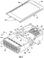
- Fig. 2 depicts a perspective top-down view of an embodiment of the cassette 100.
- the main body 110 includes a partition wall 118 extending between the sidewalls 108, end wall 106, and adapter wall 130.
- the partition wall 118 is positioned between the covers 120 forming the top wall and base wall.
- the partition wall 118 is positioned along height H between a top lip 109A and a bottom lip 109B of the sidewalls 108.
- the partition wall 118 may contour along various heights between the lips 109A, 109B, such as may be configured to alter a height of volumes 101, 102 formed between the partition wall 118 and respective covers 120.
- Embodiments of the cassette 100 include a pair of covers 120, such as a bottom cover 120B forming the base wall and a top cover 120A forming the top wall.
- the cover 120 includes a symmetrical configuration allowing the same cover configuration to be positioned as the top wall and the base wall.
- the cover 120 includes a latch 122 configured to selectively attach and release at a latch interface 123 at the sidewall 108.
- Configurations of the cover 120 including the latch 122 and the main body 110 including the latch interface 123 may obviate a requirement for a mechanical fastener (e.g., screws, nuts, bolts, threaded shanks, etc.) to retain a cover to a body.
- the latch interface 123 may form a groove, raised wall, or other surface at which the latch 122, such as forming a clip, may selectively attach and release the cover 120 from the sidewall 108.
- a cable entry passage 117 is formed at the adapter base wall 116.
- the passage 117 extends substantially along length L to allow an external cable to enter an internal volume of the cassette 100, such as further described herein and depicted in regard to Fig. 15 .
- the adapter base wall 116 forms an opening 224 configured to receive a pin 124 extending from the cover 120.
- the pin 124 may form a locating pin configured to position the cover 120 relative to the main body 110, such as to position the cover 120 as a lid over internal areas extending between the sidewalls 108, adapter wall 130, and end wall 106.
- the cover 120, sidewalls 108, end wall 106, adapter wall 130, and partition wall 118 form a volume at which splices, leads, pre-terminated fibers, and other operable components are stored and secured.
- a first volume 101 is formed between the sidewalls 108, end wall 106, adapter wall 130, a first side of the partition wall 118, and top cover 120A.
- a second volume 102 is formed between the sidewalls 108, end wall 106, adapter wall 130, a second side of the partition wall 118, and bottom cover 120B.
- the partition wall 118 includes a transition wall 105 extending along height H.
- the transition wall 105 may form a ramp contouring from proximate to the top lip 109A to proximate to the bottom lip 109B.
- the transition wall 105 is positioned along length L between the adapter wall 130 and a fiber slack storage area 140.
- the storage area 140 may be positioned along the length L proximate to the end wall 106 (e.g., distal along length L to the adapter wall 130).
- the storage area 140 forms an area at respective volumes 101, 102 at which fiber leads, excess fiber, or fiber slack is arranged, positioned, and retained.
- the transition wall 105 may extend along the height H to position fiber optic adapters 131 extending into the first volume 101 or the second volume 102.
- the transition wall 105 may substantially position an internal portion of the fiber optic adapters 131, and fiber leads 194 extending therefrom, into the first volume 101 or the second volume 102.
- the transition wall 105 may position the fiber leads 194 extending from the fiber optic adapters 131 into the second volume 102, and the transition wall 105 may substantially segregate the fiber leads 194 from the first volume 101.
- an opening may be formed through the partition wall 118 proximate to the transition wall 105, such as to allow for fiber leads to extend between volumes 101, 102.
- embodiments of the storage area 140 include an internal wall 132 partially partitioning the storage area 140 at which fiber leads may extend, wound, affix, or arrange (e.g., in loops, racetracks, figure-eight formation, etc.), such as depicted at Figs. 16-17 .
- the internal wall 132 may extend along height H from the partition wall 118 at each of volumes 101, 102.
- a tab 142 extends from the internal wall 132, such as parallel to the partition wall 118, or forming a hook, arc, finger, or other member at which fiber leads are restrained or confined to the storage area 140.
- a tab 144 extends into the volume 101, 102 from sidewall 108, end wall 106, or both.
- internal walls 132 form a passage 136 through which fiber leads may extend and arrange.
- a pair or more of internal walls 132 may form the passage 136 as a walled racetrack or conduit through which fiber leads may be positioned.
- the passage 136 is formed between the internal wall 132 and one or more of the end wall 106, the sidewall 108, or both.
- Tab 142 may extend into the passage 136, such as may extend from one or more internal walls 132 forming the passage 136, or between the internal wall 132 and the end wall 106 or sidewall 108.
- Embodiments of the cassette 100 facilitate and allow storage and organization of splice protection sleeves for splicing between internal pigtails (e.g., leads 194) and external cable 191.
- Various embodiments of the cassette 100 may include splice holder 150.
- the splice holder 150 may be configured for single discrete splices or multi-fiber ribbon splices, such as depicted at Figs. 18A-18B .
- Various embodiments of the main body 110 allow for an interchangeable modular splice holder 150 at which the single discrete splice or multi-fiber ribbon splice may be received.
- a cable ingress/egress opening 107 is formed at the sidewall 108, the end wall 106, or a transition between the sidewall 108 and the end wall 106 (e.g., at a corner connecting the sidewall 108 and end wall 106).
- Embodiments of the cable ingress/egress opening 107 may be formed extending into the first volume 101 or the second volume 102.
- the opening 107 is configured to receive a cable 191 into the cassette 100.
- the cable 191 may include a boot 192 (e.g., a strain relief boot, cable bend relief boot, or other sleeve, covering, or outer material).
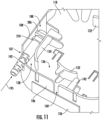
- An internal wall 134 may extend co-directional to a direction of extension (depicted schematically in Fig. 11 at arrow 195) of the cable 191 through the cable ingress/egress opening 107.
- the internal wall 134 and sidewall 108 may form a cable entry passage 138 through which the cable 191, the boot 192, or both are extended into the cassette 100.
- a fastener 188 is selectively positioned at the cable 191 or the boot 192, such as to fasten, tie down, or otherwise retain the cable 191, or portions thereof, at the cable entry passage 138.
- a fastener mount location 186 is formed extending along the direction of extension 195 ( Fig. 11 ) of the cable 191 through the opening 107.
- the fastener mount location 186 may be formed at the passage 138.
- the fastener mount location 186 may form a groove at which cable 191 (or fibers thereof) may be received and positioned.
- the fastener 188 may be positioned around the cable 191, or portions thereof, at the fastener mount location 186.
- the fastener mount location 186 forms a jacket strip or tie point at which fibers from the cable 191 are exposed within the cassette 100 and retained thereto.
- a tie point 184 is formed alongside the opening 107.
- the tie down point 184 may form a cable strength member tie point or other location at which a strength member of the cable 191 is affixed.
- FIG. 5 a perspective view of an embodiment of the cassette 100 is provided.
- the perspective view provided in Fig. 5 and the plan view provided in Fig. 16 show the first volume 101 having a first storage area 140A.
- the first volume 101 may be configured to receive an external cable 191 through cable ingress/egress opening 107.
- the first storage area 140A may include internal walls 132 and tabs 142, 144 configured to receive fiber 193 ( Fig. 16 ) from the external cable 191.
- the fiber 193 may be routed, wound, or otherwise arranged between tabs 142, 144 and the partition wall 118 and within the storage area 140A formed between internal walls 132, or furthermore between one or more sidewalls 108 or end wall 106.
- Fiber 193 is routed to the splice holder 150 at which splice protection sleeves may be positioned and affixed to the cassette 100.
- Fiber optic pigtails or splice fiber leads 194 extend from the splice holder 150.
- a passthrough opening 160 is formed through the partition wall 118 to allow the fiber leads 194 to egress from the first volume 101 to the second volume 102.
- the passthrough opening 160, or a portion thereof is formed through the sidewall 108 adjacent to the portion at the partition wall 118.
- the passthrough opening 160, or a portion thereof is formed through the end wall 106 adjacent to the portion at the partition wall 118.
- FIG. 6 a perspective view of an embodiment of the cassette 100 is provided.
- the perspective view provided in Fig. 6 and the plan view provided in Fig. 17 show the second volume 102 having a second storage area 140B.
- the second volume 102 may be configured to receive the fiber leads 194 from the first volume 101 (depicted in Figs. 5 and 16 ) through the passthrough opening 160.
- Fiber leads 194 may be routed, wound, or otherwise arranged between tabs at the second storage area 140B.
- Fiber leads 194 may terminate at fiber optic adapters 131 at the adapter wall 130. For instance, fiber optic adapters 131 may extend into the second volume 102 to allow for fiber leads 194 to extend therefrom.
- the fiber passthrough opening 160 may allow routing between the first volume 101 forming an inbound cable slack storage area and the second volume 102 forming an internal pigtail slack storage area.
- the splice holder 150 forms a splice sleeve organization area positioned at the first volume 101 (e.g., such as depicted at Figs. 3-4 ) or at the second volume 102 (e.g., such as depicted at Figs. 5-6 ).
- Figs. 7-8 depict perspective views of an embodiment of the cassette 100.
- the cover 120 and main body 110 may a release interface 121, such as a button or clip.
- the release interface 121 may be configured to allow a user to push to release the cover 120 from the main body 110.
- the release interface 121 may be positioned at the adapter base wall 116.
- a user may push the release interface 121 and translate the cover 120 along the length L toward the end wall 106, such as to remove pin 124 from opening 224.
- the user may translate the cover 120 up along the height H (i.e., away from the main body 110) to remove the cover 120, such as to remove the latch 122 from the latch interface 123.
- the latch interface 123 may form a slot extending along the length L, such as to allow for translation of the cover 120 and latch 122 along the length L.
- external cable 191 is affixed to the main body 101 using a collar 210 (e.g., a threaded collar) extending around the cable 191, such as including outer jacket 197, fiber 193 and strength member 196 (e.g., aramid or e-glass strength member), and locked in place with fastener 188 (e.g., a nut or other appropriate retainer).
- a method for assembly may include inserting the cable 191 through the collar 210.
- the method includes locking the cable 191, such as including fiber 193 and strength member 196, in place with fastener 188.
- the method may include fitting and/or retaining the fastener 188 onto the main body 110.
- the fastener 188 may be affixed to the main body 110 at the passage 138 or fastener mount location 186.
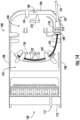
- FIG. 14 depicts an embodiment at which the cable 191 is extended into the cassette 100 through cable ingress/egress opening 107, such as described herein.
- Fig. 15 depicts an embodiment at which the cable 191 is extended into the cassette 100 through passage 117.
- Fig. 14 may depict a method for routing in which cable 191 extends into the cassette 100 through a rear end (e.g., through opening 107) and Fig.
- a cable bend relief boot (e.g., boot 192) can be used to help reduce cable bend stress as the cable 191 exits the cassette 100.
- cassette 100 such as described herein may provide an apparatus allowing for front and rear external cable entry, such as to facilitate and improve accessibility, maintenance, routing, and splicing fibers and cassettes at dataracks.
- a perspective view of an embodiment of a datarack chassis 200 is provided.
- the chassis 200 is configured to receive and retain one or more cassettes 100.
- Embodiments of the cassette 100 are mountable to chassis 200 that is mountable to a datarack.
- Various embodiments of the chassis 200 and datarack may include industry-standard configurations (e.g., 48 cm (19 inch), 53 cm (21 inch), 58 cm (23 inch), etc. industry standard width racks), or customizable-width configurations.
- the cassette 100, the chassis 200, or both, may include a depressible latch 112 configured to releasably retain the cassette 100 to the chassis 200.
- the latch 112 may allow the cassette 100 to be inserted to or removed from the chassis 200 from either a front end 211 or a rear side 212 of the chassis 200 or datarack.
- the latch 112 may be removable or positioned at the chassis 200.
- the latch 112 may be retained onto the sidewalls 108 at latch attachments 114 at an outside face of the sidewalls 108.
- the latch 112 may be retained onto the cassette 100 when the cover 120 is removed from the main body 110.
- the fastener assembly 300 includes embodiments of the collar 210 and fastener 188.
- the cable 191 includes outer jacket 197, fiber 193 and strength member 196 (e.g., aramid or e-glass strength member), such as may be included with fiber optic cable assemblies.
- the collar 210 includes a threaded shank 250 extending from one or both directions along an axial direction A from a platform 260.
- the platform 260 may form a head, such as a polygonal (e.g., hexagonal, or other multi-faceted body).
- the threaded shank 250 includes a passage 252 formed therethrough to allow the cable 191, or portions thereof, to extend through the threaded shank 250.
- Passage 252 may extend between and ends 248, 249 of the collar 210 separated along the axial direction A.
- the collar 210 extending around the outer jacket 197 has the threaded shank 250 extending co-directional to an extension of the outer jacket 197 along the axial direction A.
- a first end 248 may form an end through which the cable 191 egresses from the collar 210.
- a second end 249 may form an end through which the cable 191 enters into the collar 210 to then egress from the first end 248.
- the collar 210 includes a slot 254 extending along the axial direction A.
- the slot 254 may extend from the first end 248, such as to extend from the exit end of the collar 210 toward the platform 260.
- the slot 254 extends through the threaded shank 250, such as to allow for a portion of the cable 191 to extend from the passage 252 internal to the collar 210 to external from the collar 210.
- a method for cable retention includes extending the strength member 196 through the slot 254, such as to allow for space or separation of the strength member 196 from the fiber 193 exiting the passage 252 at the first end 248.
- embodiments of the fastener 188 may form a nut including an internally threaded passage 282 configured to engage the outer threads of the threaded shank 250 at the collar 210.
- the threads may together mate at a threaded interface 280 ( Fig. 20E ) extending from the platform 260 toward the end (e.g., first end 248) of the collar 210.
- the fastener 188 includes one or more radially extending platforms 286.
- the radially extending platforms 260, 286 have a flat radially extending interface 284 between the platforms 260, 286, such as to allow the fastener 188 to rest flush or substantially flush to the collar 210 at the platforms 260, 286.
- a groove 288 is formed between a pair of platforms 286, such as to allow a tab, member, bracket, or other feature at a casing or body to extend into the groove 288 to retain the assembly 300 to the casing or body.
- the collar 210 includes a groove 262 formed at the platform 260.
- the groove 262 extends along platform 260 at the interface 284, such as to allow a portion of the cable 191, such as the strength member 196, to extend into the groove 262, such as depicted in Fig. 20E .
- a method for cable retention may include separating the strength member 196 from the fibers 193 and extending the strength member 196 along groove 262.
- the method may include threading the fastener 188 onto the threaded shank 250 to position the platforms 260, 286 flush or substantially flush to one another.
- the strength member 196 extending through the groove 262 may allow the platforms 260, 286 to abut one another flush at the interface 284.
- Still various embodiments of the method may include positioning an end 297 of the outer jacket 197 within the passage 252.
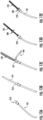
- a user may extend the cable 191 through the passage 252 and egress through end 248, such as depicted from Fig. 20A to Fig. 20B .
- the user may cut or otherwise separate the outer jacket 197 to access fibers 193, strength members 196, or other portions of the cable 191 within the outer jacket 197, such as depicted at Figs. 20C-20D .
- the user positions the fastener 188 around the fibers 193, such as through passage 282 as depicted in Fig. 20D .
- the strength member 196 extends around fastener 188, such as to bypass passage 282 through which the fibers 193 are extended.
- boot 192 may extend over the threaded shank 250 of the collar 210 from the second end 249 to the platform 286 at the fastener 188, such as depicted in Fig. 11 .
- slot 254 extends from the platform 260 toward both the first end 248 and the second end 249, such that either end 248, 249 may form an egress end of the passage 252.
- groove 262 extends on either or both sides of platform 260, such as to correspond to an extension of the slot 254 toward either end 248, 249, such as to allow either end of passage 252 to form an egress end.
- Embodiments of the assembly 300 provide structures and methods for cable retention to facilitate splicing and other work at the cable 191.
- Embodiments provided herein may mitigate shearing, crushing, stress buildup, or deterioration of portions of the cable 191.
- Groove 262 and slot 254 may facilitate separation of the strength member 196 from the fibers 193, such as to facilitate work performed at the fiber 193.
- Groove 262 may particularly promote routing and avoid damage to e-glass strength members or similar configurations.
- Slot 254 may particularly promote routing and avoid damage to aramid fiber strength members or similar configurations.
- cassette 100 allows for storage capacity of at least 1.5 meters length on 250 ⁇ m diameter fiber on internal fibers, external fibers, or both.
- the cassette 100 may include the first volume 101 and second volume 102 together having approximately 492 cubic cm (approximately 30 cubic inches) or less, or approximately 574 cubic cm (approximately 35 cubic inches) or less, or approximately 688 cubic cm (approximately 42 cubic inches) or less.
- lengths, widths, and heights of exemplary cassettes 100 may correspond to chassis 200 types such as described herein.
- Such configurations may provide desired cable length for servicing and maintenance, such as to perform splicing processes, facilitate use and length of cable, allow for re-splicing, etc.
- the cassette 100 is configured to storage desirable lengths and diameters of fiber within the volumes 101, 102, and furthermore within main bodies 110 and volumes 101, 102 allowing for a plurality of cassettes 100 to be insertable to chassis 200, such as described herein.
- Embodiments of the optical fiber cassette 100, chassis 200, and datarack depicted and described herein may improve ease of use for a user (e.g., a splicer technician) by providing separate slack storage volumes 101, 102 and facilitating fault find and trace fiber when addressing issues or performing maintenance tasks.
- Embodiments provided herein allow for installation and removal of the cassette 100 without requiring tools, such as may reduce maintenance time and reduce risk of tools damaging fiber.
- Embodiments of the cassette 100 including a fastener 188, such as forming a locking nut, facilitating reduced cable installation time and allowing cables (e.g., cable 191) to be affixed to the cassette 100 without requiring screws, inserts (e.g., molded inserts), or other threaded mechanical fasteners.
- Fastener 188 such as forming a locking nut, may save space inside the main body and facilitate ease of handling and performing splicing or maintenance tasks.
- Embodiments of the optical fiber cassette 100, chassis 200, and datarack may allow for front or rear access, such as may allow for servicing of the datarack when positioned against a wall or other obstruction.
- Embodiments provided herein facilitate use of discrete or ribbon splicing without changing configurations (i.e., discrete or ribbon splicing may be utilized at the same module), which may provide multiple configuration options at the same module.
Landscapes
- Physics & Mathematics (AREA)
- General Physics & Mathematics (AREA)
- Optics & Photonics (AREA)
- Light Guides In General And Applications Therefor (AREA)
- Mechanical Coupling Of Light Guides (AREA)
Abstract
An optical fiber cassette (100) is provided including a main body having a pair of sidewalls (108) and an end wall (106). An adapter wall (130) extends between the sidewalls (108). A partition wall extends between the sidewalls (108), the end wall (106), and the adapter wall (130). The partition wall is positioned along a height (H) between a top lip and a bottom lip of the sidewalls (108). A first volume is formed at a first side of the partition wall and a second volume is formed at a second side of the partition wall. A fiber storage area (140) is positioned at the first volume and the second volume. A splice holder (150) is positioned at the first volume or the second volume. A cable opening is configured to receive an external cable (191) into the first volume. A passthrough opening is formed to allow for fiber egress from the first volume to the second volume.
Description
- The present application claims the benefit of priority to
U.S. provisional patent application number 63/522,556 filed on June 22, 2023 U.S. provisional patent application number 63/509,621 filed on June 22, 2023 - The present disclosure relates generally to fiber optic telecommunications cassettes.
- A common scenario in fiber optic telecommunications is making optical connection points that transition from a fiber optic cable to a fiber optic connection within a module inside a modular patch panel mounted into a datarack inside a datacenter. However, when splicing fiber optic pigtails to the fiber optic cable inside a module, the available space is limited and inhibits providing fiber management, cable tie/mount points, and cable routing from front or rear of the cassette. The lack of space makes handling fiber and performing splices difficult and time consuming, which may limit the connection points that are made, prohibitively increase the cost, or potentially adversely affect quality of connection.
- Existing solutions generally require access to the rear of the datarack and may be insufficient for performing a splice operation from the front of the datarack. Generally, a splice cassette will share its fiber storage area between internal and external cable fiber, which adds to the difficulty of splicing and contributes to a risk of damage to the fiber when re-accessing the module to perform upgrades or find faults.
- An optical fiber splice and connection cassette and a datarack addressing one or more aforementioned issues would be advantageous and beneficial.
- Aspects and advantages of the invention will be set forth in part in the following description, or may be understood from the description, or may be learned through practice of the invention.
- An aspect of the present disclosure is directed to an optical fiber cassette. The cassette defines a mutually orthogonal length, width, and height, the cassette including a main body including a pair of sidewalls extending along the length and an end wall extending along the width between the pair of sidewalls, the sidewalls and the end wall each extending along the height. An adapter wall extends between the sidewalls and is positioned along the length distal to the end wall. A partition wall extends between the sidewalls, the end wall, and the adapter wall. The partition wall is positioned along the height between a top lip and a bottom lip of the sidewalls. A first volume is formed at a first side of the partition wall between the sidewalls, the end wall, and the adapter wall. A second volume is formed at a second side of the partition wall between the sidewalls, the end wall, and the adapter wall. A fiber storage area is positioned at the first volume and the second volume. A splice holder is positioned at the first volume or the second volume. A cable opening is formed at or between the end wall and at least one sidewall. The cable opening is configured to receive an external cable into the first volume. A passthrough opening is formed through the partition wall to allow for fiber egress from the first volume to the second volume.
- The adapter wall may comprise a plurality of adapters extending into the second volume.
- An adapter base wall may extend along the width between the sidewalls and partially along the length. The adapter base wall may be positioned along the length at or proximate to the adapter wall.
- A cable entry passage may be formed at the adapter base wall. The cable entry passage may extend along the length and may be configured to allow the external cable into the first volume.
- The main body may comprise a fastener mount location extending along a direction of extension of the external cable through the cable opening.
- The fastener mount location may form a groove configured to receive the external cable.
- The fastener mount location may be configured to receive a collar extended around the external cable.
- The fastener mount location may be configured to receive a fastener extended around the external cable.
- A tie point may be formed alongside the cable opening. The tie point may be configured to affix a strength member of the external cable to the main body.
- The storage area may comprise a plurality of tabs extending at least partially parallel to the partition wall.
- The storage area may comprise an internal wall extending along the height from the partition wall. A tab may extend from the internal wall at least partially parallel to the partition wall.
- The passthrough opening may be positioned alongside the end wall or the sidewall.
- The optical fiber cassette may comprise a removeable cover forming a base wall and a top wall over the main body.
- The cover may comprise a latch configured to selectively attach and release at a latch interface at the sidewall.
- The cover may comprise a face extending along the length and width. A cover sidewall and a cover end wall may extend from the face along the height.
- The sidewalls may comprise a latch attachment at an outside face of the sidewalls.
- The partition wall may comprise a transition wall extending along the height, the transition wall positioned along the length between the adapter wall and the storage area.
- The main body may be a unitary, monolithic component.
- Another aspect of the present disclosure is directed to an optical fiber cassette. The cassette defines a mutually orthogonal length, width, and height, the cassette including a main body including a pair of sidewalls extending along the length and an end wall extending along the width between the pair of sidewalls, the sidewalls and the end wall each extending along the height. An adapter wall extends between the sidewalls and is positioned along the length distal to the end wall. A partition wall extends between the sidewalls, the end wall, and the adapter wall. The partition wall is positioned along the height between a top lip and a bottom lip of the sidewalls. A first volume is formed at a first side of the partition wall between the sidewalls, the end wall, and the adapter wall. A second volume is formed at a second side of the partition wall between the sidewalls, the end wall, and the adapter wall. A fiber storage area is positioned at the first volume and the second volume. A splice holder is positioned at the first volume or the second volume. An adapter base wall extends along the width between the sidewalls and partially along the length. The adapter base wall is positioned along the length at or proximate to the adapter wall. A cable entry passage is formed at the adapter base wall. The cable entry passage is extending along the length. The cable entry passage is configured to allow the external cable into the first volume. A passthrough opening is formed through the partition wall to allow for fiber egress from the first volume to the second volume.
- A cable opening may be formed at or between the end wall and at least one sidewall, the cable opening configured to receive an external cable into the first volume.
- These and other features, aspects and advantages of the present invention will become better understood with reference to the following description and appended claims. The accompanying drawings, which are incorporated in and constitute a part of this specification, illustrate embodiments of the invention and, together with the description, serve to explain the principles of the invention.
- A full and enabling disclosure of the present invention, including the best mode thereof, directed to one of ordinary skill in the art, is set forth in the specification, which makes reference to the appended figures, in which:
-
Fig. 1 provides a perspective view of an embodiment of a telecommunications cassette in accordance with aspects of the present disclosure; -
Fig. 2 provides a perspective view of an embodiment of the telecommunications cassette viewing an interior volume in accordance with aspects of the present disclosure; -
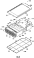
Fig. 3 provides a perspective view of an embodiment of the telecommunications cassette with covers removed in accordance with aspects of the present disclosure; -
Fig. 4 provides a perspective view of an embodiment of the telecommunications cassette with covers removed in accordance with aspects of the present disclosure; -
Fig. 5 provides a perspective view of an embodiment of a telecommunications cassette depicting a first side in accordance with aspects of the present disclosure; -
Fig. 6 provides a perspective view of an embodiment of the telecommunications cassette ofFig. 5 depicting a second side in accordance with aspects of the present disclosure; -
Fig. 7 provides a perspective view of an embodiment of the telecommunications cassette ofFig. 5 in accordance with aspects of the present disclosure; -
Fig. 8 provides a perspective view of an embodiment of the telecommunications cassette ofFig. 5 in accordance with aspects of the present disclosure; -
Fig. 9 provides a perspective view of an embodiment of the telecommunications cassette ofFig. 5 in accordance with aspects of the present disclosure; -
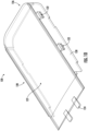
Fig. 10 provides a perspective view of an embodiment of a cover for the telecommunications cassette in accordance with aspects of the present disclosure; -
Fig. 11 provides a perspective view of an internal view of an embodiment of the telecommunications cassette in accordance with aspects of the present disclosure; -
Fig. 12 provides a perspective view of an internal view of an embodiment of the telecommunications cassette in accordance with aspects of the present disclosure; -
Fig. 13A depicts steps of a method for cable assembly to a cassette in accordance with aspects of the present disclosure; -
Fig. 13B depicts steps of the method for cable assembly to a cassette in accordance with aspects of the present disclosure; -
Fig. 13C depicts steps of the method for cable assembly to a cassette in accordance with aspects of the present disclosure; -
Fig. 13D depicts steps of the method for cable assembly to a cassette in accordance with aspects of the present disclosure; -
Fig. 13E depicts steps of the method for cable assembly to a cassette in accordance with aspects of the present disclosure; -
Fig. 14 depicts an exemplary method for routing a cable into an embodiment of the cassette in accordance with aspects of the present disclosure; -
Fig. 15 depicts an exemplary method for routing a cable into an embodiment of the cassette in accordance with aspects of the present disclosure; -
Fig. 16 provides a plan view of an exemplary cable routing at a first volume of an embodiment of the cassette in accordance with aspects of the present disclosure; -
Fig. 17 provides a plan view of an exemplary cable routing at a second volume of the embodiment of the cassette ofFig. 16 in accordance with aspects of the present disclosure; -
Fig. 18A provides an exemplary ribbon fiber splice holder of embodiments of the cassette in accordance with aspects of the present disclosure; -
Fig. 18B provides an exemplary discrete fiber splice holder of embodiments of the cassette in accordance with aspects of the present disclosure; -
Fig. 19 depicts an exemplary installation of embodiments of the cassette to an embodiment of a datarack chassis in accordance with aspects of the present disclosure -
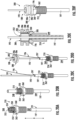
Fig. 20A provides an embodiment of a fastener assembly for a fiber optic cable and steps of a method for cable assembly to a cassette in accordance with aspects of the present disclosure; -
Fig. 20B provides an embodiment of a fastener assembly for a fiber optic cable and steps of a method for cable assembly to a cassette in accordance with aspects of the present disclosure; -
Fig. 20C provides an embodiment of a fastener assembly for a fiber optic cable and steps of a method for cable assembly to a cassette in accordance with aspects of the present disclosure; -
Fig. 20D provides an embodiment of a fastener assembly for a fiber optic cable and steps of a method for cable assembly to a cassette in accordance with aspects of the present disclosure; -
Fig. 20E provides a cross-sectional view of an exemplary embodiment of the fastener assembly at the fiber optic cable; and -
Fig. 20F provides a perspective view of an exemplary embodiment of the fastener assembly at the fiber optic cable. - Reference now will be made in detail to embodiments of the invention, one or more examples of which are illustrated in the drawings. Each example is provided by way of explanation of the invention, not limitation of the invention. In fact, it will be apparent to those skilled in the art that various modifications and variations can be made in the present invention without departing from the scope or spirit of the invention. For instance, features illustrated or described as part of one embodiment can be used with another embodiment to yield a still further embodiment. Thus, it is intended that the present invention covers such modifications and variations as come within the scope of the appended claims and their equivalents.
- Embodiments of an optical fiber cassette and a datarack addressing one or more aforementioned issues are provided. Embodiments of the optical fiber cassette may form an optical fiber splice and connection cassette or an optical fiber cassette for pre-terminated fibers. Embodiments provided herein include a module providing a protective housing for an optical fiber connection. The module may include optical fiber adapters (e.g., but not limited to, LC, SC, MPO, MDC, SN, etc. adapters), internal optical fiber pigtails, separated internal and external fiber slack storage areas (e.g., positioned at opposite sides of the cassette), cable strain relief fixing point(s), and front and rear entry/exit for fiber optic cables.
- The
cassette 100 includes amain body 110 configured to retain fiber optic adapter wall 130 (e.g.,wall 130 including a plurality of fiber optic adapters) and form a fiberslack storage area 140. Themain body 110 includes a pair ofsidewalls 108 extending along a length L. Themain body 110 includes anend wall 106 extending between thesidewalls 108 along a width W. Theend wall 106 and thesidewalls 108 extend along a height H. It should be appreciated that the length L, the width W, and the height H may extend along mutually orthogonal axes. The length L ofsidewalls 108 may generally extend greater than the width W of theend wall 106. The height H of thesidewalls 108 andend wall 106 may generally extend less than the width W or the length L. Theadapter wall 130 extends along width W betweensidewalls 108. Theend wall 106 is positioned opposite along the length L of theadapter wall 130. - In various embodiments, the
main body 110 may form a unitary, monolithic component. For instance, themain body 110 may be formed as a single molded main body. Any appropriate manufacturing method may be utilized to form themain body 110 as a unitary, monolithic component, such as, but not limited to, molding, extrusion, or additive manufacturing. - The
cassette 100 includes aremovable cover 120 providing a base wall and a top wall at themain body 110. For instance,Fig. 2 depicts a perspective top-down view of an embodiment of thecassette 100. Themain body 110 includes apartition wall 118 extending between thesidewalls 108,end wall 106, andadapter wall 130. Thepartition wall 118 is positioned between thecovers 120 forming the top wall and base wall. For instance, thepartition wall 118 is positioned along height H between atop lip 109A and abottom lip 109B of thesidewalls 108. Thepartition wall 118 may contour along various heights between thelips volumes partition wall 118 and respective covers 120. Referring toFigs. 3-4 , perspective bottom-up views of an embodiment of thecassette 100 is provided. Embodiments of thecassette 100 include a pair ofcovers 120, such as abottom cover 120B forming the base wall and atop cover 120A forming the top wall. Thecover 120 includes a symmetrical configuration allowing the same cover configuration to be positioned as the top wall and the base wall. - Referring to
Figs. 1-4 , in various embodiments, thecover 120 includes alatch 122 configured to selectively attach and release at alatch interface 123 at thesidewall 108. Configurations of thecover 120 including thelatch 122 and themain body 110 including thelatch interface 123 may obviate a requirement for a mechanical fastener (e.g., screws, nuts, bolts, threaded shanks, etc.) to retain a cover to a body. For instance, thelatch interface 123 may form a groove, raised wall, or other surface at which thelatch 122, such as forming a clip, may selectively attach and release thecover 120 from thesidewall 108. - Referring briefly to
Fig. 10 , a perspective view of an embodiment of thecover 120 is provided. Embodiments of thecover 120 may include abody having sidewalls 128 andend wall 126 extending along height H (e.g., corresponding to sidewalls 108 andend wall 106, respectively). Thecover 120 includes aface 127 extending along the length L and width W from which thesidewalls 128 andend wall 126 extend. Thecover 120 may be formed, at least in part, from a transparent material. For instance, theface 127 may be formed from a transparent material, such as, but not limited to, a plastic material, such as to allow a user to view intovolumes - In still various embodiments, an
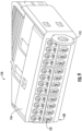
adapter base wall 116 extends along the width W between thesidewalls 108 and partially along length L corresponding to theadapter wall 130. For instance, theadapter wall 130 may form a bank of a plurality of adapters positioned between a pair ofadapter base walls 116. For instance, referring toFig. 2 , a firstadapter base wall 116A extends betweensidewalls 108 from a top portion (e.g., top lip along height H) of thesidewall 108. Referring toFig. 3 , a secondadapter base wall 116B extends betweensidewalls 108 from a bottom portion (e.g., bottom lip along height H) of thesidewall 108. In various embodiments, acable entry passage 117 is formed at theadapter base wall 116. Thepassage 117 extends substantially along length L to allow an external cable to enter an internal volume of thecassette 100, such as further described herein and depicted in regard toFig. 15 . - Referring to
Fig. 4 , in some embodiments, theadapter base wall 116 forms anopening 224 configured to receive apin 124 extending from thecover 120. Thepin 124 may form a locating pin configured to position thecover 120 relative to themain body 110, such as to position thecover 120 as a lid over internal areas extending between thesidewalls 108,adapter wall 130, and endwall 106. - In various embodiments, the
cover 120,sidewalls 108,end wall 106,adapter wall 130, andpartition wall 118 form a volume at which splices, leads, pre-terminated fibers, and other operable components are stored and secured. Referring toFig. 2 , afirst volume 101 is formed between thesidewalls 108,end wall 106,adapter wall 130, a first side of thepartition wall 118, andtop cover 120A. Referring toFig. 3 , asecond volume 102 is formed between thesidewalls 108,end wall 106,adapter wall 130, a second side of thepartition wall 118, andbottom cover 120B. - In some embodiments, the
partition wall 118 includes atransition wall 105 extending along height H. Thetransition wall 105 may form a ramp contouring from proximate to thetop lip 109A to proximate to thebottom lip 109B. Thetransition wall 105 is positioned along length L between theadapter wall 130 and a fiberslack storage area 140. For instance, thestorage area 140 may be positioned along the length L proximate to the end wall 106 (e.g., distal along length L to the adapter wall 130). Thestorage area 140 forms an area atrespective volumes - In various embodiments, the
transition wall 105 may extend along the height H to positionfiber optic adapters 131 extending into thefirst volume 101 or thesecond volume 102. For instance, thetransition wall 105 may substantially position an internal portion of thefiber optic adapters 131, and fiber leads 194 extending therefrom, into thefirst volume 101 or thesecond volume 102. For instance, referring toFig. 17 , thetransition wall 105 may position the fiber leads 194 extending from thefiber optic adapters 131 into thesecond volume 102, and thetransition wall 105 may substantially segregate the fiber leads 194 from thefirst volume 101. However, it should be appreciated that an opening may be formed through thepartition wall 118 proximate to thetransition wall 105, such as to allow for fiber leads to extend betweenvolumes - Referring at least to
Figs. 2-4 ,Figs. 6-8 , andFigs. 16-17 , embodiments of thestorage area 140 include aninternal wall 132 partially partitioning thestorage area 140 at which fiber leads may extend, wound, affix, or arrange (e.g., in loops, racetracks, figure-eight formation, etc.), such as depicted atFigs. 16-17 . For instance, theinternal wall 132 may extend along height H from thepartition wall 118 at each ofvolumes tab 142 extends from theinternal wall 132, such as parallel to thepartition wall 118, or forming a hook, arc, finger, or other member at which fiber leads are restrained or confined to thestorage area 140. In some embodiments, atab 144 extends into thevolume sidewall 108,end wall 106, or both. - Referring to
Figs. 2-4 , in some embodiments,internal walls 132 form apassage 136 through which fiber leads may extend and arrange. For instance, a pair or more ofinternal walls 132 may form thepassage 136 as a walled racetrack or conduit through which fiber leads may be positioned. In still some embodiments, thepassage 136 is formed between theinternal wall 132 and one or more of theend wall 106, thesidewall 108, or both.Tab 142 may extend into thepassage 136, such as may extend from one or moreinternal walls 132 forming thepassage 136, or between theinternal wall 132 and theend wall 106 orsidewall 108. - In various embodiments, a
splice holder 150 is selectively positioned at one or bothvolumes Figs. 18A-18B , thesplice holder 150 may be configured for fiber ribbon slack (e.g.,Fig. 18A ) or discrete fiber leads (e.g.,Fig. 18B ). However, it should be appreciated that other configurations ofsplice holder 150 may be included at thestorage area 140. In some embodiments, such as depicted atFig. 2 , thesplice holder 150 is positioned within thestorage area 140, such as adjacent to theend wall 106. In still some embodiments, such as depicted inFig. 17 , thesplice holder 150 is positioned between thestorage area 140 and theadapter wall 130, such as adjacent to thetransition wall 105. - Embodiments of the
cassette 100 facilitate and allow storage and organization of splice protection sleeves for splicing between internal pigtails (e.g., leads 194) andexternal cable 191. Various embodiments of thecassette 100 may includesplice holder 150. Thesplice holder 150 may be configured for single discrete splices or multi-fiber ribbon splices, such as depicted atFigs. 18A-18B . Various embodiments of themain body 110 allow for an interchangeablemodular splice holder 150 at which the single discrete splice or multi-fiber ribbon splice may be received. - Referring now to
Figs. 4 ,6 , and11-12 , a cable ingress/egress opening 107 is formed at thesidewall 108, theend wall 106, or a transition between thesidewall 108 and the end wall 106 (e.g., at a corner connecting thesidewall 108 and end wall 106). Embodiments of the cable ingress/egress opening 107 may be formed extending into thefirst volume 101 or thesecond volume 102. Theopening 107 is configured to receive acable 191 into thecassette 100. Thecable 191 may include a boot 192 (e.g., a strain relief boot, cable bend relief boot, or other sleeve, covering, or outer material). Aninternal wall 134 may extend co-directional to a direction of extension (depicted schematically inFig. 11 at arrow 195) of thecable 191 through the cable ingress/egress opening 107. Theinternal wall 134 andsidewall 108 may form acable entry passage 138 through which thecable 191, theboot 192, or both are extended into thecassette 100. In some embodiments, afastener 188 is selectively positioned at thecable 191 or theboot 192, such as to fasten, tie down, or otherwise retain thecable 191, or portions thereof, at thecable entry passage 138. - Referring to
Fig. 12 , in some embodiments, afastener mount location 186 is formed extending along the direction of extension 195 (Fig. 11 ) of thecable 191 through theopening 107. For instance, thefastener mount location 186 may be formed at thepassage 138. Thefastener mount location 186 may form a groove at which cable 191 (or fibers thereof) may be received and positioned. Thefastener 188 may be positioned around thecable 191, or portions thereof, at thefastener mount location 186. In some embodiments, thefastener mount location 186 forms a jacket strip or tie point at which fibers from thecable 191 are exposed within thecassette 100 and retained thereto. In still some embodiments, atie point 184 is formed alongside theopening 107. For instance, the tie downpoint 184 may form a cable strength member tie point or other location at which a strength member of thecable 191 is affixed. - Referring to
Fig. 5 , a perspective view of an embodiment of thecassette 100 is provided. The perspective view provided inFig. 5 and the plan view provided inFig. 16 show thefirst volume 101 having afirst storage area 140A. Thefirst volume 101 may be configured to receive anexternal cable 191 through cable ingress/egress opening 107. Thefirst storage area 140A may includeinternal walls 132 andtabs Fig. 16 ) from theexternal cable 191. Thefiber 193 may be routed, wound, or otherwise arranged betweentabs partition wall 118 and within thestorage area 140A formed betweeninternal walls 132, or furthermore between one or more sidewalls 108 orend wall 106.Fiber 193 is routed to thesplice holder 150 at which splice protection sleeves may be positioned and affixed to thecassette 100. Fiber optic pigtails or splice fiber leads 194 extend from thesplice holder 150. Apassthrough opening 160 is formed through thepartition wall 118 to allow the fiber leads 194 to egress from thefirst volume 101 to thesecond volume 102. In some embodiments, thepassthrough opening 160, or a portion thereof, is formed through thesidewall 108 adjacent to the portion at thepartition wall 118. In still some embodiments, such as depicted atFigs. 3-4 , thepassthrough opening 160, or a portion thereof, is formed through theend wall 106 adjacent to the portion at thepartition wall 118. - Referring to
Fig. 6 , a perspective view of an embodiment of thecassette 100 is provided. The perspective view provided inFig. 6 and the plan view provided inFig. 17 show thesecond volume 102 having asecond storage area 140B. Thesecond volume 102 may be configured to receive the fiber leads 194 from the first volume 101 (depicted inFigs. 5 and16 ) through thepassthrough opening 160. Fiber leads 194 may be routed, wound, or otherwise arranged between tabs at thesecond storage area 140B. Fiber leads 194 may terminate atfiber optic adapters 131 at theadapter wall 130. For instance,fiber optic adapters 131 may extend into thesecond volume 102 to allow for fiber leads 194 to extend therefrom. - Embodiments of the cassette at
Figs. 5 and16 may depict thefirst volume 101 as a cable tie-off or splicing region. Embodiments of thecassette 100 atFigs. 6 and17 may depict thesecond volume 102 as a optical fiber pigtail slack storage and termination region. Thecassette 100 may include a blanking plate fitted and retained to cover the cable ingress/egress opening 107 when cables are routed out of a first end (e.g., front end along length L) of thecassette 100. Themain body 110 may include thefiber passthrough opening 160 positioned at a second end (e.g., rear end along length L) or along a side (e.g., along sidewall 108) of thecassette 100. Thefiber passthrough opening 160 may allow routing between thefirst volume 101 forming an inbound cable slack storage area and thesecond volume 102 forming an internal pigtail slack storage area. In various embodiments, thesplice holder 150 forms a splice sleeve organization area positioned at the first volume 101 (e.g., such as depicted atFigs. 3-4 ) or at the second volume 102 (e.g., such as depicted atFigs. 5-6 ). -
Figs. 7-8 depict perspective views of an embodiment of thecassette 100. Thecover 120 andmain body 110 may arelease interface 121, such as a button or clip. Therelease interface 121 may be configured to allow a user to push to release thecover 120 from themain body 110. For instance, therelease interface 121 may be positioned at theadapter base wall 116. In various embodiments, a user may push therelease interface 121 and translate thecover 120 along the length L toward theend wall 106, such as to removepin 124 from opening 224. The user may translate thecover 120 up along the height H (i.e., away from the main body 110) to remove thecover 120, such as to remove thelatch 122 from thelatch interface 123. For instance, thelatch interface 123 may form a slot extending along the length L, such as to allow for translation of thecover 120 and latch 122 along the length L. - Referring now to
Figs. 13A-13E andFigs. 20A-20F , in various embodiments,external cable 191 is affixed to themain body 101 using a collar 210 (e.g., a threaded collar) extending around thecable 191, such as includingouter jacket 197,fiber 193 and strength member 196 (e.g., aramid or e-glass strength member), and locked in place with fastener 188 (e.g., a nut or other appropriate retainer). A method for assembly may include inserting thecable 191 through thecollar 210. The method includes locking thecable 191, such as includingfiber 193 andstrength member 196, in place withfastener 188. The method may include fitting and/or retaining thefastener 188 onto themain body 110. For instance, thefastener 188 may be affixed to themain body 110 at thepassage 138 orfastener mount location 186. - Referring to
Figs. 14-15 , plan views of embodiments of thecassette 100 are provided. Embodiments depicted inFigs. 14-15 may be configured substantially such as depicted and described in regard to perspective views of thecassette 100 atFigs. 3-4 .Fig. 14 depicts an embodiment at which thecable 191 is extended into thecassette 100 through cable ingress/egress opening 107, such as described herein.Fig. 15 depicts an embodiment at which thecable 191 is extended into thecassette 100 throughpassage 117. For instance,Fig. 14 may depict a method for routing in whichcable 191 extends into thecassette 100 through a rear end (e.g., through opening 107) andFig. 15 may depict a method for routing in whichcable 191 extends into thecassette 100 through a front end (e.g., through passage 117). Thecable 191 can be fitted at thefastener 188,fastener mount location 186, orpassage 138 from either front or back, such as to accommodate front or rear entry/exit of thecable 191. In still various embodiments, a cable bend relief boot (e.g., boot 192) can be used to help reduce cable bend stress as thecable 191 exits thecassette 100. - It should be appreciated that "rear" and "front" may be relative to a datarack or other cassette mounting apparatus. Embodiments of the
cassette 100 such as described herein may provide an apparatus allowing for front and rear external cable entry, such as to facilitate and improve accessibility, maintenance, routing, and splicing fibers and cassettes at dataracks. - Referring now to
Fig. 19 , a perspective view of an embodiment of adatarack chassis 200 is provided. Thechassis 200 is configured to receive and retain one ormore cassettes 100. Embodiments of thecassette 100 are mountable tochassis 200 that is mountable to a datarack. Various embodiments of thechassis 200 and datarack may include industry-standard configurations (e.g., 48 cm (19 inch), 53 cm (21 inch), 58 cm (23 inch), etc. industry standard width racks), or customizable-width configurations. Thecassette 100, thechassis 200, or both, may include adepressible latch 112 configured to releasably retain thecassette 100 to thechassis 200. Thelatch 112 may allow thecassette 100 to be inserted to or removed from thechassis 200 from either afront end 211 or arear side 212 of thechassis 200 or datarack. - In various embodiments, the
latch 112 may be removable or positioned at thechassis 200. Thelatch 112 may be retained onto thesidewalls 108 atlatch attachments 114 at an outside face of thesidewalls 108. Thelatch 112 may be retained onto thecassette 100 when thecover 120 is removed from themain body 110. - Referring now to
Figs. 20A-20F , embodiments of afiber fastener assembly 300 and method for cable retention are provided. Thefastener assembly 300 includes embodiments of thecollar 210 andfastener 188. In various embodiments, thecable 191 includesouter jacket 197,fiber 193 and strength member 196 (e.g., aramid or e-glass strength member), such as may be included with fiber optic cable assemblies. Thecollar 210 includes a threadedshank 250 extending from one or both directions along an axial direction A from aplatform 260. Theplatform 260 may form a head, such as a polygonal (e.g., hexagonal, or other multi-faceted body). The threadedshank 250 includes apassage 252 formed therethrough to allow thecable 191, or portions thereof, to extend through the threadedshank 250.Passage 252 may extend between and ends 248, 249 of thecollar 210 separated along the axial direction A. For instance, thecollar 210 extending around theouter jacket 197 has the threadedshank 250 extending co-directional to an extension of theouter jacket 197 along the axial direction A. Afirst end 248 may form an end through which thecable 191 egresses from thecollar 210. Asecond end 249 may form an end through which thecable 191 enters into thecollar 210 to then egress from thefirst end 248. - Referring particularly to
Fig. 20A , thecollar 210 includes aslot 254 extending along the axial direction A. Theslot 254 may extend from thefirst end 248, such as to extend from the exit end of thecollar 210 toward theplatform 260. Theslot 254 extends through the threadedshank 250, such as to allow for a portion of thecable 191 to extend from thepassage 252 internal to thecollar 210 to external from thecollar 210. In various embodiments, a method for cable retention includes extending thestrength member 196 through theslot 254, such as to allow for space or separation of thestrength member 196 from thefiber 193 exiting thepassage 252 at thefirst end 248. - Referring to
FIGS. 20D-20F , embodiments of thefastener 188 may form a nut including an internally threadedpassage 282 configured to engage the outer threads of the threadedshank 250 at thecollar 210. As depicted inFig. 20E , the threads may together mate at a threaded interface 280 (Fig. 20E ) extending from theplatform 260 toward the end (e.g., first end 248) of thecollar 210. - In various embodiments, the
fastener 188 includes one or more radially extendingplatforms 286. Theradially extending platforms radially extending interface 284 between theplatforms fastener 188 to rest flush or substantially flush to thecollar 210 at theplatforms groove 288 is formed between a pair ofplatforms 286, such as to allow a tab, member, bracket, or other feature at a casing or body to extend into thegroove 288 to retain theassembly 300 to the casing or body. - In still various embodiments, the
collar 210 includes agroove 262 formed at theplatform 260. Thegroove 262 extends alongplatform 260 at theinterface 284, such as to allow a portion of thecable 191, such as thestrength member 196, to extend into thegroove 262, such as depicted inFig. 20E . A method for cable retention may include separating thestrength member 196 from thefibers 193 and extending thestrength member 196 alonggroove 262. The method may include threading thefastener 188 onto the threadedshank 250 to position theplatforms strength member 196 extending through thegroove 262 may allow theplatforms interface 284.Curved edges 285 at theplatform 260 may further facilitate extension of the portion of thecable 191 into thegroove 262 while preventing shearing of the portion of the cable 191 (e.g., the strength member 196). The method may include separating thestrength member 196 from thefiber 193 via routing thestrength member 196 through thegroove 262 and thefibers 193 from thepassage 252 at thefirst end 248. Accordingly, thegroove 262 may allow thefibers 193 to egress from thepassage 252 through thefirst end 248 and allow thestrength member 196 to egress from thepassage 252 through thegroove 262, such as to facilitate separation, handling, splicing, and access to thefibers 193 and mitigate interference from other portions of thecable 191. - Still various embodiments of the method may include positioning an
end 297 of theouter jacket 197 within thepassage 252. For instance, a user may extend thecable 191 through thepassage 252 and egress throughend 248, such as depicted fromFig. 20A to Fig. 20B . The user may cut or otherwise separate theouter jacket 197 to accessfibers 193,strength members 196, or other portions of thecable 191 within theouter jacket 197, such as depicted atFigs. 20C-20D . The user positions thefastener 188 around thefibers 193, such as throughpassage 282 as depicted inFig. 20D . Thestrength member 196 extends aroundfastener 188, such as to bypasspassage 282 through which thefibers 193 are extended. The user may re-position theend 297 of the outer jacket 197 (e.g., theend 297 formed from cutting or otherwise accessing thefibers 193 within the outer jacket 197) into thepassage 252 at thecollar 210, such as depicted fromFig. 20D to Fig. 20E . In various embodiments, thestrength member 196 is positioned throughgroove 262 to allow theplatforms strength member 196 is positioned throughslot 254 to allow thestrength member 196 to extend throughfirst end 248 while allowing separation from thefibers 193 extending from thepassage 252 at thefirst end 248. - In various embodiments,
boot 192 may extend over the threadedshank 250 of thecollar 210 from thesecond end 249 to theplatform 286 at thefastener 188, such as depicted inFig. 11 . - In some embodiments,
slot 254 extends from theplatform 260 toward both thefirst end 248 and thesecond end 249, such that eitherend passage 252. In still some embodiments,groove 262 extends on either or both sides ofplatform 260, such as to correspond to an extension of theslot 254 toward eitherend passage 252 to form an egress end. - Embodiments of the
assembly 300 provide structures and methods for cable retention to facilitate splicing and other work at thecable 191. Embodiments provided herein may mitigate shearing, crushing, stress buildup, or deterioration of portions of thecable 191. Groove 262 andslot 254 may facilitate separation of thestrength member 196 from thefibers 193, such as to facilitate work performed at thefiber 193. Groove 262 may particularly promote routing and avoid damage to e-glass strength members or similar configurations.Slot 254 may particularly promote routing and avoid damage to aramid fiber strength members or similar configurations. - In an exemplary configuration of the
cassette 100,cassette 100 allows for storage capacity of at least 1.5 meters length on 250 µm diameter fiber on internal fibers, external fibers, or both. For instance, thecassette 100 may include thefirst volume 101 andsecond volume 102 together having approximately 492 cubic cm (approximately 30 cubic inches) or less, or approximately 574 cubic cm (approximately 35 cubic inches) or less, or approximately 688 cubic cm (approximately 42 cubic inches) or less. It should be appreciated that lengths, widths, and heights ofexemplary cassettes 100 may correspond tochassis 200 types such as described herein. Such configurations may provide desired cable length for servicing and maintenance, such as to perform splicing processes, facilitate use and length of cable, allow for re-splicing, etc. Thecassette 100 is configured to storage desirable lengths and diameters of fiber within thevolumes main bodies 110 andvolumes cassettes 100 to be insertable tochassis 200, such as described herein. - Embodiments of the
optical fiber cassette 100,chassis 200, and datarack depicted and described herein may improve ease of use for a user (e.g., a splicer technician) by providing separateslack storage volumes cassette 100 without requiring tools, such as may reduce maintenance time and reduce risk of tools damaging fiber. Embodiments of thecassette 100 including afastener 188, such as forming a locking nut, facilitating reduced cable installation time and allowing cables (e.g., cable 191) to be affixed to thecassette 100 without requiring screws, inserts (e.g., molded inserts), or other threaded mechanical fasteners.Fastener 188, such as forming a locking nut, may save space inside the main body and facilitate ease of handling and performing splicing or maintenance tasks. - Embodiments of the
optical fiber cassette 100,chassis 200, and datarack may allow for front or rear access, such as may allow for servicing of the datarack when positioned against a wall or other obstruction. Embodiments provided herein facilitate use of discrete or ribbon splicing without changing configurations (i.e., discrete or ribbon splicing may be utilized at the same module), which may provide multiple configuration options at the same module. - Further aspects of the invention are provided by one or more of the following embodiments:
- 1. An optical fiber cassette, the cassette defining a mutually orthogonal length, width, and height, the cassette including a main body including a pair of sidewalls extending along the length and an end wall extending along the width between the pair of sidewalls, the sidewalls and the end wall each extending along the height, wherein an adapter wall between the sidewalls and positioned along the length distal to the end wall, wherein a partition wall extends between the sidewalls, the end wall, and the adapter wall, wherein the partition wall is positioned along the height between a top lip and a bottom lip of the sidewalls, wherein a first volume is formed at a first side of the partition wall between the sidewalls, the end wall, and the adapter wall, and wherein a second volume is formed at a second side of the partition wall between the sidewalls, the end wall, and the adapter wall, wherein a fiber storage area is positioned at the first volume and the second volume, and wherein a splice holder is positioned at the first volume or the second volume, wherein a cable opening is formed at or between the end wall and at least one sidewall, the cable opening configured to receive an external cable into the first volume, and wherein a passthrough opening is formed through the partition wall to allow for fiber egress from the first volume to the second volume.
- 2. The optical fiber cassette of any one or more clauses herein, wherein the adapter wall includes a plurality of adapters extending into the second volume.
- 3. The optical fiber cassette of any one or more clauses herein, wherein an adapter base wall extends along the width between the sidewalls and partially along the length, the adapter base wall positioned along the length at or proximate to the adapter wall.
- 4. The optical fiber cassette of any one or more clauses herein, wherein a cable entry passage is formed at the adapter base wall, the cable entry passage extending along the length, the cable entry passage configured to allow the external cable into the first volume.
- 5. The optical fiber cassette of any one or more clauses herein, the main body including a fastener mount location extending along a direction of extension of the external cable through the cable opening.
- 6. The optical fiber cassette of any one or more clauses herein, wherein the fastener mount location forms a groove configured to receive the external cable.
- 7. The optical fiber cassette of any one or more clauses herein, wherein the fastener mount location is configured to receive a collar extended around the external cable.
- 8. The optical fiber cassette of any one or more clauses herein, wherein the fastener mount location is configured to receive a fastener extended around the external cable.
- 9. The optical fiber cassette of any one or more clauses herein, wherein a tie point is formed alongside the cable opening, the tie point configured to affix a strength member of the external cable to the main body.
- 10. The optical fiber cassette of any one or more clauses herein, wherein the storage area includes a plurality of tabs extending at least partially parallel to the partition wall.
- 11. The optical fiber cassette of any one or more clauses herein, wherein the storage area includes an internal wall extending along the height from the partition wall, wherein a tab extends from the internal wall at least partially parallel to the partition wall.
- 12. The optical fiber cassette of any one or more clauses herein, wherein the passthrough opening is positioned alongside the end wall or the sidewall.
- 13. The optical fiber cassette of any one or more clauses herein, including a removeable cover forming a base wall and a top wall over the main body.
- 14. The optical fiber cassette of any one or more clauses herein, the cover including a latch configured to selectively attach and release at a latch interface at the si dewall .
- 15. The optical fiber cassette of any one or more clauses herein, the cover including a pin configured to extend into an opening at an adapter base wall.
- 16. The optical fiber cassette of any one or more clauses herein, the cover including a face extending along the length and width, wherein a cover sidewall and a cover end wall extends from the face along the height.
- 17. The optical fiber cassette of any one or more clauses herein, wherein the face includes a transparent material.
- 18. The optical fiber cassette of any one or more clauses herein, the sidewalls including a latch attachment at an outside face of the sidewalls.
- 19. The optical fiber cassette of any one or more clauses herein, the partition wall including a transition wall extending along the height, the transition wall positioned along the length between the adapter wall and the storage area.
- 20. The optical fiber cassette of any one or more clauses herein, wherein the main body is a unitary, monolithic component.
- 21. An optical fiber cassette, the cassette defining a mutually orthogonal length, width, and height, the cassette including a main body including a pair of sidewalls extending along the length and an end wall extending along the width between the pair of sidewalls, the sidewalls and the end wall each extending along the height, wherein an adapter wall between the sidewalls and positioned along the length distal to the end wall, wherein a partition wall extends between the sidewalls, the end wall, and the adapter wall, wherein the partition wall is positioned along the height between a top lip and a bottom lip of the sidewalls, wherein a first volume is formed at a first side of the partition wall between the sidewalls, the end wall, and the adapter wall, and wherein a second volume is formed at a second side of the partition wall between the sidewalls, the end wall, and the adapter wall, wherein a fiber storage area is positioned at the first volume and the second volume, and wherein a splice holder is positioned at the first volume or the second volume, wherein an adapter base wall extends along the width between the sidewalls and partially along the length, the adapter base wall positioned along the length at or proximate to the adapter wall, and wherein a cable entry passage is formed at the adapter base wall, the cable entry passage extending along the length, the cable entry passage configured to allow the external cable into the first volume, and wherein a passthrough opening is formed through the partition wall to allow for fiber egress from the first volume to the second volume.
- 22. The optical fiber cassette of any one or more clauses herein, wherein a cable opening is formed at or between the end wall and at least one sidewall, the cable opening configured to receive an external cable into the first volume.
- This written description uses examples to disclose the invention, including the best mode, and also to enable any person skilled in the art to practice the invention, including making and using any devices or systems and performing any incorporated methods. The patentable scope of the invention is defined by the claims, and may include other examples that occur to those skilled in the art. Such other examples are intended to be within the scope of the claims if they include structural elements that do not differ from the literal language of the claims, or if they include equivalent structural elements with insubstantial differences from the literal languages of the claims.
Claims (15)
- An optical fiber cassette (100), the cassette (100) defining a mutually orthogonal length (L), width (W), and height (H), the cassette (100) comprising:a main body (110) comprising a pair of sidewalls (108) extending along the length (L) and an end wall (106) extending along the width (W) between the pair of sidewalls (108), the sidewalls (108) and the end wall (106) each extending along the height (H),wherein an adapter wall (130) is positioned between the sidewalls (108) and positioned along the length (L) distal to the end wall (106), wherein a partition wall (118) extends between the sidewalls (108), the end wall (106), and the adapter wall (130),wherein the partition wall (118) is positioned along the height (H) between a top lip (109A) and a bottom lip (109B) of the sidewalls (108), wherein a first volume (101) is formed at a first side of the partition wall (118) between the sidewalls (108), the end wall (106), and the adapter wall (130), and wherein a second volume (102) is formed at a second side of the partition wall (118) between the sidewalls (108), the end wall (106), and the adapter wall (130), wherein a fiber storage area (140) is positioned at the first volume (101) and the second volume (102), and wherein a splice holder (150) is positioned at the first volume (101) or the second volume (102),wherein a cable opening (107) is formed at or between the end wall (106) and at least one sidewall (108), the cable opening (107) configured to receive an external cable (191) into the first volume (101), andwherein a passthrough opening (160) is formed through the partition wall (118) to allow for fiber egress from the first volume (101) to the second volume (102).
- An optical fiber cassette (100) according to claim 1, wherein the adapter wall (130) comprises a plurality of adapters (131) extending into the second volume (102).
- An optical fiber cassette (100) according to claim 1 or claim 2, wherein an adapter base wall (116) extends along the width (W) between the sidewalls (108) and partially along the length (L), the adapter base wall (116) positioned along the length (L) at or proximate to the adapter wall (130).
- An optical fiber cassette (100) according to claim 3, wherein a cable entry passage (138) is formed at the adapter base wall (116), the cable entry passage (138) extending along the length (L), the cable entry passage (138) configured to allow the external cable (191) into the first volume (101).
- An optical fiber cassette (100) according to any preceding claim, the main body (110) comprising a fastener mount location (186) extending along a direction of extension of the external cable (191) through the cable opening (107), wherein the fastener mount location (186) optionally forms a groove configured to receive the external cable (191), or is optionally configured to receive a collar (210) or fastener (188) extended around the external cable (191).
- An optical fiber cassette (100) according to any preceding claim, wherein a tie point (184) is formed alongside the cable opening (107), the tie point (184) configured to affix a strength member (196) of the external cable (191) to the main body (110).
- An optical fiber cassette (100) according to any preceding claim, wherein the storage area (140) comprises a plurality of tabs (142, 144) extending at least partially parallel to the partition wall (118).
- An optical fiber cassette (100) according to any preceding claim, wherein the storage area (140) comprises an internal wall (132) extending along the height (H) from the partition wall (118), wherein a tab (142) extends from the internal wall (132) at least partially parallel to the partition wall (118).
- An optical fiber cassette (100) according to any preceding claim, wherein the passthrough opening (160) is positioned alongside the end wall (106) or the sidewall (108).
- An optical fiber cassette (100) according to any preceding claim, comprising:
a removeable cover (120) forming a base wall (120B) and a top wall (120A) over the main body (110), the cover (120) optionally comprising a latch (122) configured to selectively attach and release at a latch interface (123) at the side wall (108), and/or optionally comprising a face (127) extending along the length (L) and width (W), wherein a cover sidewall (128) and a cover end wall (126) extends from the face (127) along the height (H). - An optical fiber cassette (100) according to any preceding claim, the sidewalls (108) comprising a latch attachment (114) at an outside face of the sidewalls (108).
- An optical fiber cassette (100) according to any preceding claim, the partition wall (118) comprising a transition wall (105) extending along the height (H), the transition wall (105) positioned along the length (L) between the adapter wall (130) and the storage area (140).
- An optical fiber cassette (100) according to any preceding claim, wherein the main body (110) is a unitary, monolithic component.
- An optical fiber cassette (100), the cassette (100) defining a mutually orthogonal length (L), width (W), and height (H), the cassette (100) comprising:a main body (110) comprising a pair of sidewalls (108) extending along the length (L) and an end wall (106) extending along the width (W) between the pair of sidewalls (108), the sidewalls (108) and the end wall (106) each extending along the height (H),wherein an adapter wall (130) is positioned between the sidewalls (108) and positioned along the length (L) distal to the end wall (106), wherein a partition wall (118) extends between the sidewalls (108), the end wall (106), and the adapter wall (130),wherein the partition wall (188) is positioned along the height (H) between a top lip (109A) and a bottom lip (109) of the sidewalls (108), wherein a first volume (101) is formed at a first side of the partition wall (118) between the sidewalls (108), the end wall (106), and the adapter wall (130), and wherein a second volume (102) is formed at a second side of the partition wall (118) between the sidewalls (108), the end wall (106), and the adapter wall (130), wherein a fiber storage area (140) is positioned at the first volume (101) and the second volume (102), and wherein a splice holder (150) is positioned at the first volume (101) or the second volume (102),wherein an adapter base wall (116) extends along the width (W) between the sidewalls (108) and partially along the length (L), the adapter base wall (116) positioned along the length (L) at or proximate to the adapter wall (130), and wherein a cable entry passage (138) is formed at the adapter base wall (116), the cable entry passage (138) extending along the length (L), the cable entry passage (138) configured to allow the external cable (191) into the first volume (101), andwherein a passthrough opening (160) is formed through the partition wall (118) to allow for fiber egress from the first volume (101) to the second volume (102).
- An optical fiber cassette (100) according to claim 14, wherein a cable opening (107) is formed at or between the end wall (106) and at least one sidewall (108), the cable opening (107) configured to receive the external cable (191) into the first volume (101).
Applications Claiming Priority (2)
| Application Number | Priority Date | Filing Date | Title |
|---|---|---|---|
| US202363522556P | 2023-06-22 | 2023-06-22 | |
| US202363509621P | 2023-06-22 | 2023-06-22 |
Publications (1)
| Publication Number | Publication Date |
|---|---|
| EP4488735A1 true EP4488735A1 (en) | 2025-01-08 |
Family
ID=91432969
Family Applications (3)
| Application Number | Title | Priority Date | Filing Date |
|---|---|---|---|
| EP24182436.6A Pending EP4481453A1 (en) | 2023-06-22 | 2024-06-14 | Fiber optic cable fastener assembly |
| EP24182434.1A Pending EP4488735A1 (en) | 2023-06-22 | 2024-06-14 | Optical fiber cassette |
| EP24182438.2A Pending EP4481454A1 (en) | 2023-06-22 | 2024-06-14 | Optical fiber cassette |
Family Applications Before (1)
| Application Number | Title | Priority Date | Filing Date |
|---|---|---|---|
| EP24182436.6A Pending EP4481453A1 (en) | 2023-06-22 | 2024-06-14 | Fiber optic cable fastener assembly |
Family Applications After (1)
| Application Number | Title | Priority Date | Filing Date |
|---|---|---|---|
| EP24182438.2A Pending EP4481454A1 (en) | 2023-06-22 | 2024-06-14 | Optical fiber cassette |
Country Status (3)
| Country | Link |
|---|---|
| US (3) | US20240427102A1 (en) |
| EP (3) | EP4481453A1 (en) |
| CN (3) | CN119179151A (en) |
Families Citing this family (2)
| Publication number | Priority date | Publication date | Assignee | Title |
|---|---|---|---|---|
| US20240411100A1 (en) * | 2023-06-12 | 2024-12-12 | Belden Canada Ulc | Cable entry transition to a cassette for a fiber optic cable configured to reduce stress on an optical fiber and reduce signal loss |
| US20240427102A1 (en) * | 2023-06-22 | 2024-12-26 | Afl Telecommunications Llc | Optical fiber cassette |
Citations (3)
| Publication number | Priority date | Publication date | Assignee | Title |
|---|---|---|---|---|
| US20160161693A1 (en) * | 2010-06-18 | 2016-06-09 | Adc Communications (Shanghai) Co., Ltd. | Fiber optic enclosure with internal cable spool |
| US10514518B1 (en) * | 2019-03-25 | 2019-12-24 | Connectivity Solutions Direct LLC | Dense optical termination and patching platforms, systems, and methods |
| US20210364721A1 (en) * | 2018-03-26 | 2021-11-25 | CommScope Connectivity Belgium BVBA | Field repairable fiber optic cassette |
Family Cites Families (73)
| Publication number | Priority date | Publication date | Assignee | Title |
|---|---|---|---|---|
| US4447120A (en) * | 1981-10-05 | 1984-05-08 | International Telephone & Telegraph Corporation | Fiber optic cable clamp |
| EP0131283A3 (en) * | 1983-07-07 | 1985-09-11 | Augat Inc. | Method and apparatus for anchoring optical cables to optical connectors |
| US4898448A (en) * | 1988-05-02 | 1990-02-06 | Gte Products Corporation | Fiber distribution panel |
| US5071211A (en) * | 1988-12-20 | 1991-12-10 | Northern Telecom Limited | Connector holders and distribution frame and connector holder assemblies for optical cable |
| US5100221A (en) * | 1990-01-22 | 1992-03-31 | Porta Systems Corp. | Optical fiber cable distribution frame and support |
| US5167001A (en) * | 1991-09-03 | 1992-11-24 | Northern Telecom Limited | Optical fiber storage and connector tray and shelf and tray assembly |
| US5644673A (en) * | 1996-01-16 | 1997-07-01 | Lockheed Martin Corp. | Optical-fiber-cable to bulkhead connector |
| US6496638B1 (en) * | 1998-10-23 | 2002-12-17 | Lucent Technologies Inc. | Optical fiber cassette |
| US7220144B1 (en) * | 2000-02-01 | 2007-05-22 | Adc Telecommunications, Inc. | Multimedia outlet box |
| GB0108255D0 (en) * | 2001-04-02 | 2001-05-23 | Tyco Electronics Raychem Nv | Optical fibre organiser |
| US6804447B2 (en) * | 2002-11-05 | 2004-10-12 | Adc Telecommunications, Inc. | Fiber panel with integrated couplers |
| US7142764B2 (en) * | 2003-03-20 | 2006-11-28 | Tyco Electronics Corporation | Optical fiber interconnect cabinets, termination modules and fiber connectivity management for the same |
| US7346253B2 (en) * | 2003-12-24 | 2008-03-18 | Corning Cable Systems Llc | Fiber optic drop cable slack storage receptacle |
| US7120347B2 (en) * | 2004-01-27 | 2006-10-10 | Corning Cable Systems Llc | Multi-port optical connection terminal |
| US20050232565A1 (en) * | 2004-04-16 | 2005-10-20 | Ross Heggestad | Normal through optical panel |
| US7171100B2 (en) * | 2004-11-03 | 2007-01-30 | Adc Telecommunications, Inc. | Optical fiber slack storage tray for distribution cabinet |
| US7400813B2 (en) * | 2005-05-25 | 2008-07-15 | Adc Telecommunications, Inc. | Fiber optic splitter module |
| DE102005052882B4 (en) * | 2005-11-07 | 2011-12-01 | Adc Gmbh | Method and device for coupling optical waveguides |
| US7760984B2 (en) * | 2006-05-04 | 2010-07-20 | Adc Telecommunications, Inc. | Fiber distribution hub with swing frame and wrap-around doors |
| US7391952B1 (en) * | 2006-08-31 | 2008-06-24 | Corning Cable Systems Llc | Pre-connectorized fiber optic cable network interconnection apparatus |
| RU2451957C2 (en) * | 2006-09-13 | 2012-05-27 | 3М Инновейтив Пропертиз Компани | System for maintenance of fire-optic circuits with splice tray |
| US7570861B2 (en) * | 2007-01-19 | 2009-08-04 | Adc Telecommunications, Inc. | Adapter panel with lateral sliding adapter arrays |
| US7822310B2 (en) * | 2007-02-28 | 2010-10-26 | Corning Cable Systems Llc | Fiber optic splice trays |
| US7509016B2 (en) * | 2007-03-09 | 2009-03-24 | Adc Telecommunications, Inc. | Telecommunication rack unit tray |
| US8039745B2 (en) * | 2007-08-01 | 2011-10-18 | Panduit Corp. | Cable strain relief module assembly |
| US8059932B2 (en) * | 2007-10-01 | 2011-11-15 | Clearfield, Inc. | Modular optical fiber cassette |
| US7758389B2 (en) * | 2008-01-25 | 2010-07-20 | Tyco Electronics Corporation | Connector assembly having a movable plug |
| CN101521545B (en) * | 2008-02-27 | 2012-10-10 | 3M创新有限公司 | High-density optical fiber distributing hub |
| US8009954B2 (en) * | 2008-04-21 | 2011-08-30 | Adc Telecommunications, Inc. | Fiber optic splice tray |
| US8573859B2 (en) * | 2008-06-06 | 2013-11-05 | 3M Innovative Properties Company | Field terminable optical fiber connector with splice element |
| EP2296023B1 (en) * | 2008-07-10 | 2017-08-09 | Fujikura Ltd. | Optical connector and method for assembling optical connector |
| US8086084B2 (en) * | 2008-09-09 | 2011-12-27 | Adc Telecommunications, Inc. | Fiber optic splice tray |
| US8265447B2 (en) * | 2008-09-16 | 2012-09-11 | Adc Telecommunications, Inc. | Modular fiber optic enclosure with external cable spool |
| EP2508928B1 (en) * | 2008-09-23 | 2015-08-19 | 3M Innovative Properties Company | Enclosure for telecommunications cables, with removable organizer |
| US8879882B2 (en) * | 2008-10-27 | 2014-11-04 | Corning Cable Systems Llc | Variably configurable and modular local convergence point |
| US8081857B2 (en) * | 2008-12-31 | 2011-12-20 | Opterna Am, Inc. | System for an internal rotating storage spool combined with top and bottom cable access in a fiber distribution terminal |
| EP2380054A1 (en) * | 2009-01-15 | 2011-10-26 | ADC Telecommunications, INC. | Fiber optic module, chassis and adapter |
| US9116310B2 (en) * | 2009-03-06 | 2015-08-25 | Adc Telecommunications, Inc. | Fiber optic cable pass-thru fitting with a cable retention member for routing strength members |
| WO2011112705A2 (en) * | 2010-03-11 | 2011-09-15 | Adc Telecommunications, Inc. | Fiber optic enclosure with internal cable spool assembly |
| CN102985859A (en) * | 2010-04-23 | 2013-03-20 | Ccs技术公司 | Removable fiber optic splice tray |
| US8385711B2 (en) * | 2010-04-30 | 2013-02-26 | Corning Cable Systems Llc | Multi-configurable splice holder |
| US8660397B2 (en) * | 2010-04-30 | 2014-02-25 | Corning Cable Systems Llc | Multi-layer module |
| US8915659B2 (en) * | 2010-05-14 | 2014-12-23 | Adc Telecommunications, Inc. | Splice enclosure arrangement for fiber optic cables |
| WO2011163464A2 (en) * | 2010-06-23 | 2011-12-29 | Adc Telecommunications, Inc. | Telecommunications assembly |
| US8718436B2 (en) * | 2010-08-30 | 2014-05-06 | Corning Cable Systems Llc | Methods, apparatuses for providing secure fiber optic connections |
| WO2012074688A2 (en) * | 2010-12-01 | 2012-06-07 | 3M Innovative Properties Company | Fiber organizer and distribution box |
| US8876407B2 (en) * | 2011-05-25 | 2014-11-04 | Tyco Electronics Corporation | Cable anchoring system |
| US8873926B2 (en) * | 2012-04-26 | 2014-10-28 | Corning Cable Systems Llc | Fiber optic enclosures employing clamping assemblies for strain relief of cables, and related assemblies and methods |
| CA2874487A1 (en) * | 2012-05-25 | 2013-11-28 | Adc Telecommunications, Inc. | Splice cassettes and chips |
| US9442265B2 (en) * | 2012-09-18 | 2016-09-13 | Clearfield, Inc. | Optical fiber management system |
| EP2917774A1 (en) * | 2012-11-07 | 2015-09-16 | Tyco Electronics Raychem BVBA | Rapid distribution terminal |
| CN105324696B (en) * | 2012-12-19 | 2019-05-17 | 泰科电子瑞侃有限公司 | Distribution device with progressively increasing splitters |
| US9720198B2 (en) * | 2013-07-23 | 2017-08-01 | Panduit Corp. | Strain relief for armored cable |
| US9851524B2 (en) * | 2014-01-28 | 2017-12-26 | Commscope Technologies Llc | Slidable fiber optic connection module with cable slack management |
| US9535230B2 (en) * | 2014-01-31 | 2017-01-03 | Senko Advanced Components, Inc. | Integrated fiber optic cable fan-out connector |
| US9575274B2 (en) * | 2014-02-25 | 2017-02-21 | Commscope Technologies Llc | Fiber management structure having a splice tray with modular elements |
| WO2016004347A1 (en) * | 2014-07-03 | 2016-01-07 | Adc Telecommunications, Inc. | Optical fiber connector for multi-fiber cable |
| WO2016191094A1 (en) * | 2015-05-27 | 2016-12-01 | 3M Innovative Properties Company | Fiber management assemblies and network interface devices incorporating such assemblies |
| MX367607B (en) * | 2015-11-03 | 2019-08-28 | Perez Davila William | Connector assembly for fiber optic cables having absorption of inner stresses and inner sealing for mounting in a fiber optic connection box. |
| US9720199B2 (en) * | 2016-01-06 | 2017-08-01 | FiberOne LLC | Optical fiber cassette with bend limiting and connector shield |
| WO2017162751A1 (en) * | 2016-03-23 | 2017-09-28 | CommScope Connectivity Belgium BVBA | Module and enclosure for use therein |
| US10359590B2 (en) * | 2016-04-04 | 2019-07-23 | Opterna Technology Limited | Fiber optic cable deployment assemblies, systems, and methods |
| US9632267B1 (en) * | 2016-04-05 | 2017-04-25 | Ofs Fitel, Llc | Compact point-of-entry fiber storage module |
| US10585256B1 (en) * | 2019-03-29 | 2020-03-10 | Corning Research & Development Corporation | Terminal of an optical fiber network having a bypass module |
| WO2021041305A1 (en) * | 2019-08-26 | 2021-03-04 | Commscope Technologies Llc | Fiber optic connectors and fiber optic connection systems |
| US10715271B1 (en) * | 2019-09-30 | 2020-07-14 | Corning Research & Development Corporation | Dense wavelength division multiplexing fiber optic apparatuses and related equipment |
| US11036020B2 (en) * | 2019-10-10 | 2021-06-15 | Telect, Inc. | Outside plant data communication systems |
| US12276856B2 (en) * | 2020-05-06 | 2025-04-15 | Commscope Technologies Llc | Splice enclosure with connectorized patching functionality |
| CN215529503U (en) * | 2021-05-31 | 2022-01-14 | 康普技术有限责任公司 | Telecommunications enclosure including an organizing member |
| US12253732B2 (en) * | 2021-06-23 | 2025-03-18 | Corning Research & Development Corporation | Fiber optic assembly with splice tray |
| WO2022271913A1 (en) * | 2021-06-23 | 2022-12-29 | Commscope Technologies Llc | Sealed fiber optic adapters and fiber optic connection systems |
| US12282198B2 (en) * | 2021-11-10 | 2025-04-22 | Corning Research & Development Corporation | Dense wavelength division multiplexing modulization system |
| US20240427102A1 (en) * | 2023-06-22 | 2024-12-26 | Afl Telecommunications Llc | Optical fiber cassette |
-
2024
- 2024-01-25 US US18/422,472 patent/US20240427102A1/en active Pending
- 2024-01-25 US US18/422,419 patent/US20240427103A1/en active Pending
- 2024-01-25 US US18/422,444 patent/US20240427104A1/en active Pending
- 2024-03-07 CN CN202410260014.0A patent/CN119179151A/en active Pending
- 2024-03-07 CN CN202410257401.9A patent/CN119179142A/en active Pending
- 2024-03-07 CN CN202410258696.1A patent/CN119179150A/en active Pending
- 2024-06-14 EP EP24182436.6A patent/EP4481453A1/en active Pending
- 2024-06-14 EP EP24182434.1A patent/EP4488735A1/en active Pending
- 2024-06-14 EP EP24182438.2A patent/EP4481454A1/en active Pending
Patent Citations (3)
| Publication number | Priority date | Publication date | Assignee | Title |
|---|---|---|---|---|
| US20160161693A1 (en) * | 2010-06-18 | 2016-06-09 | Adc Communications (Shanghai) Co., Ltd. | Fiber optic enclosure with internal cable spool |
| US20210364721A1 (en) * | 2018-03-26 | 2021-11-25 | CommScope Connectivity Belgium BVBA | Field repairable fiber optic cassette |
| US10514518B1 (en) * | 2019-03-25 | 2019-12-24 | Connectivity Solutions Direct LLC | Dense optical termination and patching platforms, systems, and methods |
Also Published As
| Publication number | Publication date |
|---|---|
| CN119179150A (en) | 2024-12-24 |
| US20240427102A1 (en) | 2024-12-26 |
| EP4481454A1 (en) | 2024-12-25 |
| CN119179142A (en) | 2024-12-24 |
| US20240427103A1 (en) | 2024-12-26 |
| CN119179151A (en) | 2024-12-24 |
| US20240427104A1 (en) | 2024-12-26 |
| EP4481453A1 (en) | 2024-12-25 |
Similar Documents
| Publication | Publication Date | Title |
|---|---|---|
| EP4481454A1 (en) | Optical fiber cassette | |
| US12265274B2 (en) | Rapid universal rack mount enclosure | |
| US7277614B2 (en) | Tether assembly having individual connector ports | |
| EP2646867B1 (en) | Fiber device holder and strain relief device | |
| US7869681B2 (en) | Optical connection closure having at least one connector port for optically connecting a drop cable to a distribution cable | |
| EP1944635A2 (en) | Wall-mountable optical fiber and cable management apparatus | |
| CA3017686A1 (en) | High density distribution frame with an integrated splicing compartment | |
| EP3460552B1 (en) | Behind-the-wall fiber spool module | |
| US20260072230A1 (en) | Rack mounted enclosure | |
| US20120256526A1 (en) | Fiber optic cabinet | |
| US20210341697A1 (en) | Fiber management system and method for a telecommunication terminal | |
| US12444915B2 (en) | Management device for hybrid cable | |
| US20260079316A1 (en) | Splice Holder with Fiber Optic Connectors | |
| AU2015202664B2 (en) | Telecommunications assembly | |
| US20250244551A1 (en) | Multi-spool cable reel | |
| EP4597188A1 (en) | Optical fiber drop enclosure | |
| CA3286340A1 (en) | Splice tray with holders for fiber optic adapters | |
| HK1069878B (en) | Fiber termination block with angled slide |
Legal Events
| Date | Code | Title | Description |
|---|---|---|---|
| PUAI | Public reference made under article 153(3) epc to a published international application that has entered the european phase |
Free format text: ORIGINAL CODE: 0009012 |
|
| STAA | Information on the status of an ep patent application or granted ep patent |
Free format text: STATUS: THE APPLICATION HAS BEEN PUBLISHED |
|
| AK | Designated contracting states |
Kind code of ref document: A1 Designated state(s): AL AT BE BG CH CY CZ DE DK EE ES FI FR GB GR HR HU IE IS IT LI LT LU LV MC ME MK MT NL NO PL PT RO RS SE SI SK SM TR |
|
| STAA | Information on the status of an ep patent application or granted ep patent |
Free format text: STATUS: REQUEST FOR EXAMINATION WAS MADE |
|
| 17P | Request for examination filed |
Effective date: 20250704 |