EP4488693A1 - Low side lobe level aesa hybrid fate / ensemble calibration - Google Patents
Low side lobe level aesa hybrid fate / ensemble calibration Download PDFInfo
- Publication number
- EP4488693A1 EP4488693A1 EP24183555.2A EP24183555A EP4488693A1 EP 4488693 A1 EP4488693 A1 EP 4488693A1 EP 24183555 A EP24183555 A EP 24183555A EP 4488693 A1 EP4488693 A1 EP 4488693A1
- Authority
- EP
- European Patent Office
- Prior art keywords
- esa
- far field
- amplitude
- calibrated
- antenna
- Prior art date
- Legal status (The legal status is an assumption and is not a legal conclusion. Google has not performed a legal analysis and makes no representation as to the accuracy of the status listed.)
- Pending
Links
Images


Classifications
-
- G—PHYSICS
- G01—MEASURING; TESTING
- G01R—MEASURING ELECTRIC VARIABLES; MEASURING MAGNETIC VARIABLES
- G01R29/00—Arrangements for measuring or indicating electric quantities not covered by groups G01R19/00 - G01R27/00
- G01R29/08—Measuring electromagnetic field characteristics
- G01R29/10—Radiation diagrams of antennas
-
- H—ELECTRICITY
- H01—ELECTRIC ELEMENTS
- H01Q—ANTENNAS, i.e. RADIO AERIALS
- H01Q3/00—Arrangements for changing or varying the orientation or the shape of the directional pattern of the waves radiated from an antenna or antenna system
- H01Q3/26—Arrangements for changing or varying the orientation or the shape of the directional pattern of the waves radiated from an antenna or antenna system varying the relative phase or relative amplitude of energisation between two or more active radiating elements; varying the distribution of energy across a radiating aperture
- H01Q3/267—Phased-array testing or checking devices
-
- G—PHYSICS
- G01—MEASURING; TESTING
- G01S—RADIO DIRECTION-FINDING; RADIO NAVIGATION; DETERMINING DISTANCE OR VELOCITY BY USE OF RADIO WAVES; LOCATING OR PRESENCE-DETECTING BY USE OF THE REFLECTION OR RERADIATION OF RADIO WAVES; ANALOGOUS ARRANGEMENTS USING OTHER WAVES
- G01S7/00—Details of systems according to groups G01S13/00, G01S15/00, G01S17/00
- G01S7/02—Details of systems according to groups G01S13/00, G01S15/00, G01S17/00 of systems according to group G01S13/00
- G01S7/40—Means for monitoring or calibrating
- G01S7/4004—Means for monitoring or calibrating of parts of a radar system
-
- G—PHYSICS
- G01—MEASURING; TESTING
- G01S—RADIO DIRECTION-FINDING; RADIO NAVIGATION; DETERMINING DISTANCE OR VELOCITY BY USE OF RADIO WAVES; LOCATING OR PRESENCE-DETECTING BY USE OF THE REFLECTION OR RERADIATION OF RADIO WAVES; ANALOGOUS ARRANGEMENTS USING OTHER WAVES
- G01S7/00—Details of systems according to groups G01S13/00, G01S15/00, G01S17/00
- G01S7/02—Details of systems according to groups G01S13/00, G01S15/00, G01S17/00 of systems according to group G01S13/00
- G01S7/40—Means for monitoring or calibrating
- G01S7/4052—Means for monitoring or calibrating by simulation of echoes
- G01S7/4082—Means for monitoring or calibrating by simulation of echoes using externally generated reference signals, e.g. via remote reflector or transponder
- G01S7/4086—Means for monitoring or calibrating by simulation of echoes using externally generated reference signals, e.g. via remote reflector or transponder in a calibrating environment, e.g. anechoic chamber
-
- H—ELECTRICITY
- H01—ELECTRIC ELEMENTS
- H01Q—ANTENNAS, i.e. RADIO AERIALS
- H01Q3/00—Arrangements for changing or varying the orientation or the shape of the directional pattern of the waves radiated from an antenna or antenna system
- H01Q3/26—Arrangements for changing or varying the orientation or the shape of the directional pattern of the waves radiated from an antenna or antenna system varying the relative phase or relative amplitude of energisation between two or more active radiating elements; varying the distribution of energy across a radiating aperture
- H01Q3/28—Arrangements for changing or varying the orientation or the shape of the directional pattern of the waves radiated from an antenna or antenna system varying the relative phase or relative amplitude of energisation between two or more active radiating elements; varying the distribution of energy across a radiating aperture varying the amplitude
-
- H—ELECTRICITY
- H01—ELECTRIC ELEMENTS
- H01Q—ANTENNAS, i.e. RADIO AERIALS
- H01Q3/00—Arrangements for changing or varying the orientation or the shape of the directional pattern of the waves radiated from an antenna or antenna system
- H01Q3/26—Arrangements for changing or varying the orientation or the shape of the directional pattern of the waves radiated from an antenna or antenna system varying the relative phase or relative amplitude of energisation between two or more active radiating elements; varying the distribution of energy across a radiating aperture
- H01Q3/30—Arrangements for changing or varying the orientation or the shape of the directional pattern of the waves radiated from an antenna or antenna system varying the relative phase or relative amplitude of energisation between two or more active radiating elements; varying the distribution of energy across a radiating aperture varying the relative phase between the radiating elements of an array
- H01Q3/34—Arrangements for changing or varying the orientation or the shape of the directional pattern of the waves radiated from an antenna or antenna system varying the relative phase or relative amplitude of energisation between two or more active radiating elements; varying the distribution of energy across a radiating aperture varying the relative phase between the radiating elements of an array by electrical means
- H01Q3/36—Arrangements for changing or varying the orientation or the shape of the directional pattern of the waves radiated from an antenna or antenna system varying the relative phase or relative amplitude of energisation between two or more active radiating elements; varying the distribution of energy across a radiating aperture varying the relative phase between the radiating elements of an array by electrical means with variable phase-shifters
-
- G—PHYSICS
- G01—MEASURING; TESTING
- G01R—MEASURING ELECTRIC VARIABLES; MEASURING MAGNETIC VARIABLES
- G01R35/00—Testing or calibrating of apparatus covered by the other groups of this subclass
-
- H—ELECTRICITY
- H04—ELECTRIC COMMUNICATION TECHNIQUE
- H04B—TRANSMISSION
- H04B17/00—Monitoring; Testing
- H04B17/10—Monitoring; Testing of transmitters
- H04B17/11—Monitoring; Testing of transmitters for calibration
- H04B17/12—Monitoring; Testing of transmitters for calibration of transmit antennas, e.g. of the amplitude or phase
Definitions
- AESAs Active electronically scanned arrays
- Calibration of AESAs has traditionally been limited to the generation of high accuracy phase and gain calibration coefficients required to achieve low side lobe far field radiation patterns. Coefficients generated by such calibration are in units of dB (for gain) and degrees (for phase). In practice, applying these calibration coefficients involves passing the gain and phase values into a gain table and a phase table.
- These tables may be generated during calibration or may be provided in the RFIC datasheet, but typically the RFIC data sheet input alone is insufficient as the circuit and radiating aperture contribute to the above-mentioned phase and amplitude errors and must also be compensated for in the calibration process.
- Amplitude and phase errors typically worsen with the lower gain settings that are required for low side lobe operation.
- Less than 25 dBp AESA side lobe levels typically require greater than 10 dB amplitude variation from the aperture center to the aperture periphery.
- Mutual coupling / scan impedance changes as a function of scan, which provides suboptimum termination (i.e., impedance mismatch) to RFIC components. Impacts of gain and phase variation after calibration become pronounced when applying a low SLL taper.
- Low Side Lobe level AESA calibration is traditionally a difficult process, requiring specialized near field or far field ranges to sample the fields radiated from (or received by) the AESA under test. These ranges can become prohibitively expensive, require extensive design and analysis, as well as sophisticated mechanical alignment systems to ensure test and measurement accuracy. The slow calibration and test validation execution times of these types of approaches are very unattractive for high throughput production.
- AESA calibration techniques include near field range holographic back projection that requires repetitive full near field scans to drive errors in the aperture hologram to zero, which is time consuming; and planar, cylindrical, or spherical near field ranges, which are expensive and require a large footprint (facility floor space).
- Repetitive near field range holographic back projection convergence calibration is accurate but time consuming (e.g., approximately 1 -hour elapsed calibration execution time for 3 back projections with commensurate T / R amplitude and phase adjustment iterations for a 1024 element AESA at single frequency and single beam pointing angle).
- Far field anechoic chambers are slow, expensive, and have a large footprint. The are also AESA physical size and weight limitations. A far field compact range is also slow and expensive, with AESA physical size and weight limitations. Other calibration techniques have been limited to gentle side lobe tapers required for SATCOM.
- embodiments of the inventive concepts disclosed herein are directed to a calibration system for AESAs.
- An initial calibration is performed according to known methodologies. Near field measurements are then taken to obtain the AESA far field radiation pattern and complex aperture holograms. Based on the complex holograms, phase and amplitude error maps are computed. T / R module amplitude and phase are then adjusted to compensate for the error map.
- the system switches back to the far field radiation pattern and commensurate aperture hologram back projection to iteratively recompute far field corrections and new hologram error maps until a desired level of precision is reached.
- inventive concepts are not limited in their application to the arrangement of the components or steps or methodologies set forth in the following description or illustrated in the drawings.
- inventive concepts disclosed herein may be practiced without these specific details.
- well-known features may not be described in detail to avoid unnecessarily complicating the instant disclosure.
- inventive concepts disclosed herein are capable of other embodiments or of being practiced or carried out in various ways. Also, it is to be understood that the phraseology and terminology employed herein is for the purpose of description and should not be regarded as limiting.
- a letter following a reference numeral is intended to reference an embodiment of a feature or element that may be similar, but not necessarily identical, to a previously described element or feature bearing the same reference numeral (e.g., 1, 1a, 1b).
- reference numeral e.g. 1, 1a, 1b
- Such shorthand notations are used for purposes of convenience only, and should not be construed to limit the inventive concepts disclosed herein in any way unless expressly stated to the contrary.
- any reference to "one embodiment,” or “some embodiments” means that a particular element, feature, structure, or characteristic described in connection with the embodiment is included in at least one embodiment of the inventive concepts disclosed herein.
- the appearances of the phrase “in at least one embodiment” in the specification does not necessarily refer to the same embodiment.
- Embodiments of the inventive concepts disclosed may include one or more of the features expressly described or inherently present herein, or any combination or sub-combination of two or more such features.
- embodiments of the inventive concepts disclosed herein are directed to a calibration system wherein an initial calibration is performed according to known methodologies. Near field measurements are then taken to obtain the AESA far field radiation pattern, and complex aperture holograms. Based on the complex holograms, phase and amplitude error maps are computed. T / R module amplitude and phase are then adjusted to compensate for the error map. The system switches back to the far field radiation pattern and commensurate aperture hologram back projection to iteratively recompute far field corrections and new hologram error maps until a desired level of precision is reached.
- the AESA-based RF system 100 includes a processor 102 and memory 104 storing processor executable code for configuring the processor 102 to apply signals to an AESA 106.
- a plurality of sensors 108 or sensor packages are disposed proximal to the ESA 106, in a near field range test environment configuration, to directly receive signals from different radiating elements of the ESA 106 at one time.
- Such embodiment may or may not include a motor 108 or actuator to rotate the ESA 106.
- the sensors 108 are in data communication with the processor 102; in at least one embodiment, multiple sensors 108 are coherent with each other such that data points may be correlated in time and potentially in orientation to the ESA 106 where the ESA 106 not stationary (e.g., where the ESA 106 in conformal and is rotated to make distinct portions of the ESA 106 orthogonal to the sensors 108).
- the processor 102 preloads initial, theoretically derived, perfect ESA targets (potentially stored in a data storage element 110) in the ESAT / R modules.
- the sensors 108 take planar near field measurements and the processor 102 calculates far field radiation patterns and various first order models according to near field range algorithms.
- the processor 102 produces element specific far field correction factors based on the far field radiation patterns and first order models, as compared to the known, perfect AESA targets.
- the processor 102 when measuring a tapered array, the side lobe levels are often insufficient for certain applications after calibration. Using the near field range, it is possible to get a projection of a hologram onto the aperture and fine tune the results from the calibration.
- the near field range is the gold standard for ESA 106 performance. Therefore, the processor 102 also calculates complex aperture holograms are calculated.
- the processor 102 compares hologram amplitudes and phase data to desired amplitude and phase targets from a data storage element 110. Based on that comparison, the processor 102 calculates phase and amplitude error maps across the face of the ESA 106. Holograms are back projections of the data collected by the sensors 108 (near field scanners). Such holograms are mapped onto a model of the ESA 106. Phase offsets and gain offsets for each radiating element are identified based on the hologram mapped model. The T / R modules' amplitude and phase are adjusted to compensate for the error maps.
- the processor 102 performs another planar near field measurement to determine far field radiation patterns via the adjusted T / R modules.
- the steps may be iteratively performed until the ESA 106 is calibrated within some desired level of precision.
- the desired level of precision may be defined by a threshold side lobe level.
- FIG. 2 a block diagram of a system for calibrating an ESA is shown.
- a processor configures ESA beamformer chips to step through the entire calibration sequence.
- Signals are collected by a test probe 206 disposed in the anechoic box 202 and delivered to test equipment 208.
- the test equipment 208 may include a signal analyzer and network analyzer.
- a far field phase and amplitude correction to account for the non-idealness of probe 216 can be included in the overall calibration scheme.
- a processor produces ESA calibration coefficients specific to the ESA 200 based on signal data from the network analyzer.
- FIG. 2 illustrates the calibration set up for a planar AESA for simplicity. This block diagram can be further extended / generalized to accomplish robust calibration methodologies for singly and doubly curved conformal AESA architectures.
- Phase coding utilizes waveform orthogonality between the radiating elements 204 and the test probe 206 based on the Hadamard linear algebra theory.
- the orthogonality properties of the Hadamard sequence essentially de-correlates the radiating elements 204 such that they operate as a collection of distinct, uncorrelated and independent RF channels.
- the application of Hadamard orthogonal coding and linear algebra may be better understood with reference to Seth D. Silverstein Application of Orthogonal Codes to the Calibration of Active Phased Array Antenna for Communication Satellites (IEEE Transactions on Signal Processing, Vol. 45, No. 1, 1997 ), which is hereby incorporated by reference.
- Each radiating element 204, RF channel operates in a far field radiation mode, in an uncorrelated aggregate fashion, while being simultaneously transmitted or received.
- the test probe 206 receives or transmits the uncorrelated radiating element 204, RF channel signals.
- the phase and amplitude coding can also utilize non-Hadamard encoding techniques.
- the individual channels are parsed out of the aggregate received or transmitted signal.
- the mean path length, test probe 206, and test horn antenna radiation patterns are mathematically removed from the data set to reveal the amplitude and phase shift of each RF channel.
- Hadamard matrices may be used to measure individual radiating element 204 gain and phase response.
- the calibration process described herein defines a far field calibration portion and a near field calibration portion based on back projection holograms.
- Near field back projection to obtain the aperture hologram may include near field methodologies such as planar, cylindric, spherical, planar-polar, etc.
- far field techniques may be applicable for specialized applications such as very large ground based AESAs.
- the entire process may be performed in a single near field range test environment.
- the ESA 200 may be transferred as necessary between test environments.
- a calibrating system drives 300 the radiating elements of an AESA according to predefined, ideal ESA amplitude and phase targets in a near field test range environment.
- Sensors receive 302 signals from the radiating elements.
- Complex AESA aperture amplitude and phase calibration coefficients required for low-side lobe far field radiation patterns are calculated 304 based on those signals. Such calculation 304 may be by a best-fit algorithm.
- calibration allows a conformal, non-planar ESA to operate in a narrow band.
- arbitrary surface shapes may be calibrated via group delay for ultra-wideband systems; in such embodiment, time delay may be the factor being calibrated for the ultra-wideband array as opposed to phase delay.
- group delay performance is determined via partial derivatives taken at specific frequencies. Alternatively, or in addition, group delay performance is determined is taken directly from a network analyzer measurement of group delay.
- the calibration process may be generalized to multidimensional calibration algorithms as a function of, for example, beam scan / pointing, polarization state, dynamic beam shape control, temperature (in the case of in situ calibration where an anechoic box is adapted to a standard environmental test chamber), etc.
- the ESA undergoes far field calibration; then the ESA is transferred to a planar or near field range.
- far field calibration is performed in the near field range.
- complex aperture holograms are calculated 306.
- Near field range algorithms produce robust aperture holograms.
- the hologram output files are compared 308 to desired phase and amplitude targets.
- a phase and amplitude error map is computed across the entire array face.
- the T / R modules amplitude and phase are adjusted 310 to compensate for the error map.
- Near field range algorithms to obtain the aperture holograms are very robust, mature, and National Institute of Standards and Technology (NIST) traceable for maximum accuracy, resolution, and precision.
- new planar near field measurements are taken 302 based on the update T / R modules.
- the process may be repeated iteratively to arrive at a desired level of precision / performance.
- Data link, directional comm, Radar and SATCOM AESAs have different crucial parameters for calibration.
- Existing calibration techniques are well suited for calibrating the crucial parameters necessary for SATCOM because such systems do not require very low-side lobes levels to meet systems requirements unlike general radar application.
- one of the critical parameters for radar e.g., X band multi-function radar AESAs
- Low side lobe operation is desirable when creating nulls in the radiation pattern.
- Embodiments of the present disclosure are suitable for low side lobe calibration.
- embodiments of the present disclosure allow for precise calibration in minutes as compared to hours using existing techniques.
- Embodiments of the present disclosure enable quick calibration and production testing of small arrays; the principles are also applicable to hybrid far field / near field calibration.
Landscapes
- Engineering & Computer Science (AREA)
- Physics & Mathematics (AREA)
- Radar, Positioning & Navigation (AREA)
- Remote Sensing (AREA)
- General Physics & Mathematics (AREA)
- Computer Networks & Wireless Communication (AREA)
- Electromagnetism (AREA)
- Radar Systems Or Details Thereof (AREA)
- Variable-Direction Aerials And Aerial Arrays (AREA)
Abstract
A calibration system (100) for AESAs induces the AESA to produce a far field radiation pattern while near field measurements are taken; an initial calibration is produced, and complex aperture holograms are calculated. Based on the complex holograms, phase and amplitude error maps are computed. T / R module amplitude and phase are then adjusted to compensate for the error map. The system (100) evaluates the refined far field radiation pattern to iteratively recompute complex aperture excitations to realize adequate far field performance and new hologram error maps until a desired level of precision is reached.
Description
- Active electronically scanned arrays (AESAs) used in various avionics systems require Low Side Lobe operation. Low side lobe operation across an AESA's scan volume requires very precise calibration to correct electrical phase and amplitude errors in the RF channels, aperture tolerances, part-to-part variation in RFIC performance, and variation over temperature and frequency. Calibration of AESAs has traditionally been limited to the generation of high accuracy phase and gain calibration coefficients required to achieve low side lobe far field radiation patterns. Coefficients generated by such calibration are in units of dB (for gain) and degrees (for phase). In practice, applying these calibration coefficients involves passing the gain and phase values into a gain table and a phase table. These tables may be generated during calibration or may be provided in the RFIC datasheet, but typically the RFIC data sheet input alone is insufficient as the circuit and radiating aperture contribute to the above-mentioned phase and amplitude errors and must also be compensated for in the calibration process.
- Reliance on a single gain and phase table for a full array will result in residual gain and phase errors after calibration due to part-to-part variation and tolerance within the AESA's passive radio frequency (RF) circuitry. Low side lobe AESA precision is extremely sensitive to phase and amplitude errors in the AESA's passive RF combiner circuits, the active RFIC beam former, and T / R module RFICs and the passive radiation aperture. Effective calibration needs to be within tenths of dBs in amplitude and no more than a few degrees of phase.
- Amplitude and phase errors typically worsen with the lower gain settings that are required for low side lobe operation. Less than 25 dBp AESA side lobe levels typically require greater than 10 dB amplitude variation from the aperture center to the aperture periphery. Mutual coupling / scan impedance changes as a function of scan, which provides suboptimum termination (i.e., impedance mismatch) to RFIC components. Impacts of gain and phase variation after calibration become pronounced when applying a low SLL taper.
- Low Side Lobe level AESA calibration is traditionally a difficult process, requiring specialized near field or far field ranges to sample the fields radiated from (or received by) the AESA under test. These ranges can become prohibitively expensive, require extensive design and analysis, as well as sophisticated mechanical alignment systems to ensure test and measurement accuracy. The slow calibration and test validation execution times of these types of approaches are very unattractive for high throughput production.
- Current state-of-the-industry AESA calibration techniques include near field range holographic back projection that requires repetitive full near field scans to drive errors in the aperture hologram to zero, which is time consuming; and planar, cylindrical, or spherical near field ranges, which are expensive and require a large footprint (facility floor space). Repetitive near field range holographic back projection convergence calibration is accurate but time consuming (e.g., approximately 1 -hour elapsed calibration execution time for 3 back projections with commensurate T / R amplitude and phase adjustment iterations for a 1024 element AESA at single frequency and single beam pointing angle).
- Far field anechoic chambers are slow, expensive, and have a large footprint. The are also AESA physical size and weight limitations. A far field compact range is also slow and expensive, with AESA physical size and weight limitations. Other calibration techniques have been limited to gentle side lobe tapers required for SATCOM.
- It would be advantageous to have a system and method for AESA calibration for low side level AESA calibration.
- In one aspect, embodiments of the inventive concepts disclosed herein are directed to a calibration system for AESAs. An initial calibration is performed according to known methodologies. Near field measurements are then taken to obtain the AESA far field radiation pattern and complex aperture holograms. Based on the complex holograms, phase and amplitude error maps are computed. T / R module amplitude and phase are then adjusted to compensate for the error map.
- In a further aspect, the system switches back to the far field radiation pattern and commensurate aperture hologram back projection to iteratively recompute far field corrections and new hologram error maps until a desired level of precision is reached.
- It is to be understood that both the foregoing general description and the following detailed description are exemplary and explanatory only and should not restrict the scope of the claims. The accompanying drawings, which are incorporated in and constitute a part of the specification, illustrate exemplary embodiments of the inventive concepts disclosed herein and together with the general description, serve to explain the principles.
- The numerous advantages of the embodiments of the inventive concepts disclosed herein may be better understood by those skilled in the art by reference to the accompanying figures in which:
-
FIG. 1 shows a block diagram of a system useful for implementing exemplary embodiments of the present disclosure; -
FIG. 2 shows a block diagram of a system for calibrating an ESA; -
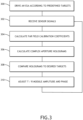
FIG. 3 shows a flowchart of an exemplary embodiment of a method for calibrating an ESA; - Before explaining various embodiments of the inventive concepts disclosed herein in detail, it is to be understood that the inventive concepts are not limited in their application to the arrangement of the components or steps or methodologies set forth in the following description or illustrated in the drawings. In the following detailed description of embodiments of the instant inventive concepts, numerous specific details are set forth in order to provide a more thorough understanding of the inventive concepts. However, it will be apparent to one of ordinary skill in the art having the benefit of the instant disclosure that the inventive concepts disclosed herein may be practiced without these specific details. In other instances, well-known features may not be described in detail to avoid unnecessarily complicating the instant disclosure. The inventive concepts disclosed herein are capable of other embodiments or of being practiced or carried out in various ways. Also, it is to be understood that the phraseology and terminology employed herein is for the purpose of description and should not be regarded as limiting.
- As used herein a letter following a reference numeral is intended to reference an embodiment of a feature or element that may be similar, but not necessarily identical, to a previously described element or feature bearing the same reference numeral (e.g., 1, 1a, 1b). Such shorthand notations are used for purposes of convenience only, and should not be construed to limit the inventive concepts disclosed herein in any way unless expressly stated to the contrary.
- Further, unless expressly stated to the contrary, "or" refers to an inclusive or and not to an exclusive or. For example, a condition A or B is satisfied by anyone of the following: A is true (or present) and B is false (or not present), A is false (or not present) and B is true (or present), and both A and B are true (or present).
- In addition, use of "a" or "an" are employed to describe elements and components of embodiments of the instant inventive concepts. This is done merely for convenience and to give a general sense of the inventive concepts, and "a" and "an" are intended to include one or at least one and the singular also includes the plural unless it is obvious that it is meant otherwise.
- Also, while various components may be depicted as being connected directly, direct connection is not a requirement. Components may be in data communication with intervening components that are not illustrated or described.
- Finally, as used herein any reference to "one embodiment," or "some embodiments" means that a particular element, feature, structure, or characteristic described in connection with the embodiment is included in at least one embodiment of the inventive concepts disclosed herein. The appearances of the phrase "in at least one embodiment" in the specification does not necessarily refer to the same embodiment. Embodiments of the inventive concepts disclosed may include one or more of the features expressly described or inherently present herein, or any combination or sub-combination of two or more such features.
- Broadly, embodiments of the inventive concepts disclosed herein are directed to a calibration system wherein an initial calibration is performed according to known methodologies. Near field measurements are then taken to obtain the AESA far field radiation pattern, and complex aperture holograms. Based on the complex holograms, phase and amplitude error maps are computed. T / R module amplitude and phase are then adjusted to compensate for the error map. The system switches back to the far field radiation pattern and commensurate aperture hologram back projection to iteratively recompute far field corrections and new hologram error maps until a desired level of precision is reached.
- Referring to
FIG. 1 , a block diagram of asystem 100 useful for implementing exemplary embodiments of the present disclosure is shown. The AESA-basedRF system 100 includes aprocessor 102 andmemory 104 storing processor executable code for configuring theprocessor 102 to apply signals to an AESA 106. - In at least one embodiment, a plurality of
sensors 108 or sensor packages are disposed proximal to the ESA 106, in a near field range test environment configuration, to directly receive signals from different radiating elements of the ESA 106 at one time. Such embodiment, may or may not include amotor 108 or actuator to rotate the ESA 106. Thesensors 108 are in data communication with theprocessor 102; in at least one embodiment,multiple sensors 108 are coherent with each other such that data points may be correlated in time and potentially in orientation to theESA 106 where theESA 106 not stationary (e.g., where theESA 106 in conformal and is rotated to make distinct portions of theESA 106 orthogonal to the sensors 108). - The
processor 102 preloads initial, theoretically derived, perfect ESA targets (potentially stored in a data storage element 110) in the ESAT / R modules. Thesensors 108 take planar near field measurements and theprocessor 102 calculates far field radiation patterns and various first order models according to near field range algorithms. Theprocessor 102 produces element specific far field correction factors based on the far field radiation patterns and first order models, as compared to the known, perfect AESA targets. - In the near field range, when measuring a tapered array, the side lobe levels are often insufficient for certain applications after calibration. Using the near field range, it is possible to get a projection of a hologram onto the aperture and fine tune the results from the calibration. The near field range is the gold standard for
ESA 106 performance. Therefore, theprocessor 102 also calculates complex aperture holograms are calculated. - Once the aperture phase and amplitude correction factors required for low-side far field radiation patterns are applied, the
processor 102 compares hologram amplitudes and phase data to desired amplitude and phase targets from adata storage element 110. Based on that comparison, theprocessor 102 calculates phase and amplitude error maps across the face of theESA 106. Holograms are back projections of the data collected by the sensors 108 (near field scanners). Such holograms are mapped onto a model of theESA 106. Phase offsets and gain offsets for each radiating element are identified based on the hologram mapped model. The T / R modules' amplitude and phase are adjusted to compensate for the error maps. - In at least one embodiment, once the T / R module amplitude and phase adjustments are determined, the
processor 102 performs another planar near field measurement to determine far field radiation patterns via the adjusted T / R modules. In at least one embodiment, the steps may be iteratively performed until theESA 106 is calibrated within some desired level of precision. The desired level of precision may be defined by a threshold side lobe level. - Referring to
FIG. 2 , a block diagram of a system for calibrating an ESA is shown. When calibrating anESA 200 in ananechoic box 202, each radiatingelement 204 is driven a defined calibration sequence, a processor configures ESA beamformer chips to step through the entire calibration sequence. Signals are collected by atest probe 206 disposed in theanechoic box 202 and delivered to testequipment 208. Thetest equipment 208 may include a signal analyzer and network analyzer. A far field phase and amplitude correction to account for the non-idealness of probe 216 can be included in the overall calibration scheme. A processor produces ESA calibration coefficients specific to theESA 200 based on signal data from the network analyzer.FIG. 2 illustrates the calibration set up for a planar AESA for simplicity. This block diagram can be further extended / generalized to accomplish robust calibration methodologies for singly and doubly curved conformal AESA architectures. - Phase coding utilizes waveform orthogonality between the radiating
elements 204 and thetest probe 206 based on the Hadamard linear algebra theory. The orthogonality properties of the Hadamard sequence essentially de-correlates the radiatingelements 204 such that they operate as a collection of distinct, uncorrelated and independent RF channels. The application of Hadamard orthogonal coding and linear algebra may be better understood with reference to Seth D. Silverstein Application of Orthogonal Codes to the Calibration of Active Phased Array Antenna for Communication Satellites (IEEE Transactions on Signal Processing, Vol. 45, No. 1, 1997), which is hereby incorporated by reference. Each radiatingelement 204, RF channel operates in a far field radiation mode, in an uncorrelated aggregate fashion, while being simultaneously transmitted or received. Thetest probe 206 receives or transmits theuncorrelated radiating element 204, RF channel signals. The phase and amplitude coding can also utilize non-Hadamard encoding techniques. - Since the modulation sequence is known a priori, the individual channels are parsed out of the aggregate received or transmitted signal. The mean path length,
test probe 206, and test horn antenna radiation patterns are mathematically removed from the data set to reveal the amplitude and phase shift of each RF channel. In at least one embodiment, Hadamard matrices may be used to measureindividual radiating element 204 gain and phase response. - The calibration process described herein defines a far field calibration portion and a near field calibration portion based on back projection holograms. Near field back projection to obtain the aperture hologram may include near field methodologies such as planar, cylindric, spherical, planar-polar, etc. Furthermore, far field techniques may be applicable for specialized applications such as very large ground based AESAs. In at least one embodiment, the entire process may be performed in a single near field range test environment. Alternatively, the
ESA 200 may be transferred as necessary between test environments. - Referring to
FIG. 3 , a flowchart of an exemplary embodiment of a method for calibrating a conformal ESA is shown. A calibrating system drives 300 the radiating elements of an AESA according to predefined, ideal ESA amplitude and phase targets in a near field test range environment. Sensors receive 302 signals from the radiating elements. Complex AESA aperture amplitude and phase calibration coefficients required for low-side lobe far field radiation patterns are calculated 304 based on those signals.Such calculation 304 may be by a best-fit algorithm. - In at least one embodiment, calibration allows a conformal, non-planar ESA to operate in a narrow band. Alternatively, or in addition, arbitrary surface shapes may be calibrated via group delay for ultra-wideband systems; in such embodiment, time delay may be the factor being calibrated for the ultra-wideband array as opposed to phase delay.
- In at least one embodiment, group delay performance is determined via partial derivatives taken at specific frequencies. Alternatively, or in addition, group delay performance is determined is taken directly from a network analyzer measurement of group delay.
- In at least one embodiment, the calibration process may be generalized to multidimensional calibration algorithms as a function of, for example, beam scan / pointing, polarization state, dynamic beam shape control, temperature (in the case of in situ calibration where an anechoic box is adapted to a standard environmental test chamber), etc.
- In at least one embodiment, the ESA undergoes far field calibration; then the ESA is transferred to a planar or near field range. Alternatively, far field calibration is performed in the near field range. While performing planar near field measurements to obtain the far field radiation patterns, complex aperture holograms are calculated 306. Near field range algorithms produce robust aperture holograms. The hologram output files are compared 308 to desired phase and amplitude targets. A phase and amplitude error map is computed across the entire array face. The T / R modules amplitude and phase are adjusted 310 to compensate for the error map. Near field range algorithms to obtain the aperture holograms are very robust, mature, and National Institute of Standards and Technology (NIST) traceable for maximum accuracy, resolution, and precision.
- In at least one embodiment, new planar near field measurements are taken 302 based on the update T / R modules. The process may be repeated iteratively to arrive at a desired level of precision / performance.
- Data link, directional comm, Radar and SATCOM AESAs, e.g., have different crucial parameters for calibration. Existing calibration techniques are well suited for calibrating the crucial parameters necessary for SATCOM because such systems do not require very low-side lobes levels to meet systems requirements unlike general radar application. However, one of the critical parameters for radar (e.g., X band multi-function radar AESAs) is low side lobe operation. Low side lobe operation is desirable when creating nulls in the radiation pattern. Embodiments of the present disclosure are suitable for low side lobe calibration. Furthermore, embodiments of the present disclosure allow for precise calibration in minutes as compared to hours using existing techniques. Embodiments of the present disclosure enable quick calibration and production testing of small arrays; the principles are also applicable to hybrid far field / near field calibration.
- It is believed that the inventive concepts disclosed herein and many of their attendant advantages will be understood by the foregoing description of embodiments of the inventive concepts, and it will be apparent that various changes may be made in the form, construction, and arrangement of the components thereof without departing from the broad scope of the inventive concepts disclosed herein or without sacrificing all of their material advantages; and individual features from various embodiments may be combined to arrive at other embodiments. The forms herein before described being merely explanatory embodiments thereof, it is the intention of the following claims to encompass and include such changes. Furthermore, any of the features disclosed in relation to any of the individual embodiments may be incorporated into any other embodiment.
Claims (15)
- A computer apparatus comprising:one or more sensors (108); andat least one processor (102) in data communication with a memory storing processor executable code for configuring the at least one processor (102) to:drive radiating elements in an electronically scanned array (ESA) antenna being calibrated when the ESA is in a transmit mode;receive signals from the one or more sensors (108) based on the driven radiating elements when the ESA is in a receive mode;calculate far field calibration coefficients for each of the radiating elements;calculate one or more error maps corresponding to a face of the ESA antenna being calibrated; anddetermine amplitude and phase adjustments for one or more T / R modules in the ESA being calibrated.
- The computer apparatus of Claim 1, wherein the at least one processor (102) is further configured to:apply the amplitude and phase adjustments to the one or more T / R modules in the ESA being calibrated; andrecalculate far field calibration coefficients for each of the radiating elements.
- The computer apparatus of Claim 2, wherein the amplitude and phase adjustments recalculated far field calibration coefficients produce side lobe levels of less than -30 dBp in the receive mode.
- The computer apparatus of Claim 2, wherein the at least one processor (102) is further configured to iteratively recalculate aperture amplitude and phase or delay calibration coefficients and redetermine amplitude and phase adjustments until a threshold precision is reached for desired far field performance, and optionally wherein the threshold precision is defined by a far field null depth, width, and azimuthal and elevation location.
- The computer apparatus of any preceding Claim, wherein the error maps are defined by complex aperture holograms.
- The computer apparatus of any preceding Claim, wherein the ESA antenna being calibrated is disposed in a near field range test environment.
- A method comprising:driving radiating elements in an electronically scanned array (ESA) antenna being calibrated;receiving signals based on the driven radiating elements;calculating far field calibration coefficients for each of the radiating elements;calculating one or more error maps corresponding to a face of the ESA antenna being calibrated; anddetermining amplitude and phase adjustments for one or more T / R modules in the ESA being calibrated.
- The method of Claim 7, further comprising:applying the amplitude and phase adjustments to the one or more T / R modules in the ESA being calibrated while in a transmit mode; andrecalculating far field calibration coefficients for each of the radiating elements.
- The method of Claim 8, wherein the amplitude and phase adjustments recalculated far field calibration coefficients produce far field nulls, and optionally wherein the threshold precision is defined by a far field null depth, width, and azimuthal and elevation location.
- The method of Claim 7, 8 or 9, further comprising iteratively recalculating far field calibration coefficients and redetermining amplitude and phase adjustments until a threshold precision is reached.
- The method of Claim 7, 8, 9 or 10, wherein the error maps are defined by complex aperture holograms; and/or wherein the ESA antenna being calibrated is disposed in a near field range test environment.
- An antenna calibration system comprising:a near field range test environment;one or more sensors (108) disposed in the near field range test environment; andat least one processor (102) in data communication with a memory storing processor executable code for configuring the at least one processor (102) to:drive radiating elements in an electronically scanned array (ESA) antenna being calibrated when in a transmit mode;receive signals from the one or more sensors (108) based on the driven radiating elements when the ESA is in a receive mode;calculate complex aperture calibration coefficients for each of the radiating elements;calculate one or more error maps corresponding to a face of the ESA antenna being calibrated; anddetermine amplitude and phase adjustments for one or more T / R modules in the ESA being calibrated.
- The antenna calibration system of Claim 12, wherein the at least one processor (102) is further configured to:apply the amplitude and phase adjustments to the one or more T / R modules in the ESA being calibrated; andrecalculate far field calibration coefficients for each of the radiating elements.
- The antenna calibration system of Claim 13, wherein the amplitude and phase adjustments recalculated far field calibration coefficients produce far field nulls according to desired width, depth, and azimuthal and elevation location; and/or wherein the at least one processor (102) is further configured to iteratively recalculate far field calibration coefficients and redetermine amplitude and phase adjustments until a threshold precision is reached, and optionally wherein the threshold precision is defined by a desired side lobe level.
- The antenna calibration system of any of Claims 12-14, wherein the error maps are defined by complex aperture holograms.
Applications Claiming Priority (1)
| Application Number | Priority Date | Filing Date | Title |
|---|---|---|---|
| US18/216,429 US20250007155A1 (en) | 2023-06-29 | 2023-06-29 | Low side lobe level aesa hybrid fate / ensemble calibration |
Publications (1)
| Publication Number | Publication Date |
|---|---|
| EP4488693A1 true EP4488693A1 (en) | 2025-01-08 |
Family
ID=91620608
Family Applications (1)
| Application Number | Title | Priority Date | Filing Date |
|---|---|---|---|
| EP24183555.2A Pending EP4488693A1 (en) | 2023-06-29 | 2024-06-20 | Low side lobe level aesa hybrid fate / ensemble calibration |
Country Status (2)
| Country | Link |
|---|---|
| US (1) | US20250007155A1 (en) |
| EP (1) | EP4488693A1 (en) |
Citations (7)
| Publication number | Priority date | Publication date | Assignee | Title |
|---|---|---|---|---|
| US5412414A (en) * | 1988-04-08 | 1995-05-02 | Martin Marietta Corporation | Self monitoring/calibrating phased array radar and an interchangeable, adjustable transmit/receive sub-assembly |
| EP1178562A1 (en) * | 2000-08-03 | 2002-02-06 | Telefonaktiebolaget L M Ericsson (Publ) | Antenna array calibration |
| US20160211577A1 (en) * | 2015-01-19 | 2016-07-21 | Raytheon Corporation | Side Lobe Modulation System and Related Techniques |
| EP3876438A1 (en) * | 2020-03-05 | 2021-09-08 | Rockwell Collins, Inc. | Conformal esa calibration |
| EP3917040A1 (en) * | 2020-05-29 | 2021-12-01 | Rockwell Collins, Inc. | Efficient in situ radiative loop back aesa calibration and prognostic health monitoring |
| US20220247501A1 (en) * | 2021-01-29 | 2022-08-04 | Arizona Board Of Regents On Behalf Of Arizona State University | Hybrid in-situ and signal of opportunity calibration for antenna arrays |
| US20230006754A1 (en) * | 2019-12-10 | 2023-01-05 | Macdonald, Dettwiler And Associates Corporation | System and method for remotely calibrating a phased array antenna |
Family Cites Families (9)
| Publication number | Priority date | Publication date | Assignee | Title |
|---|---|---|---|---|
| US9409151B1 (en) * | 2012-08-29 | 2016-08-09 | Rockwell Collins, Inc. | Calibration and optimization of ESA in aircraft radomes |
| US10109915B2 (en) * | 2014-02-13 | 2018-10-23 | The United States Of America As Represented By The Secretary Of The Navy | Planar near-field calibration of digital arrays using element plane wave spectra |
| US9360549B1 (en) * | 2014-06-05 | 2016-06-07 | Thales-Raytheon Systems Company Llc | Methods and apparatus for a self-calibrated signal injection setup for in-field receive phased array calibration system |
| US9614279B2 (en) * | 2014-08-11 | 2017-04-04 | Raytheon Company | Portable apparatus and associated method for phased array field calibration |
| US9705611B1 (en) * | 2016-03-24 | 2017-07-11 | Rockwell Collins, Inc. | Systems and methods for array antenna calibration |
| US10965386B1 (en) * | 2020-03-06 | 2021-03-30 | Rockwell Collins, Inc. | System and method for calibrating antenna array |
| US11811461B2 (en) * | 2021-01-15 | 2023-11-07 | National Taiwan University | Calibration method for a phased array of antennas |
| US12052063B2 (en) * | 2022-05-17 | 2024-07-30 | Rockwell Collins, Inc. | Low SLL AESA taper calibration |
| FR3151944B1 (en) * | 2023-08-04 | 2026-01-02 | Thales Sa | Improved method for far-field calibration of a network antenna and calibrated network antenna |
-
2023
- 2023-06-29 US US18/216,429 patent/US20250007155A1/en active Pending
-
2024
- 2024-06-20 EP EP24183555.2A patent/EP4488693A1/en active Pending
Patent Citations (7)
| Publication number | Priority date | Publication date | Assignee | Title |
|---|---|---|---|---|
| US5412414A (en) * | 1988-04-08 | 1995-05-02 | Martin Marietta Corporation | Self monitoring/calibrating phased array radar and an interchangeable, adjustable transmit/receive sub-assembly |
| EP1178562A1 (en) * | 2000-08-03 | 2002-02-06 | Telefonaktiebolaget L M Ericsson (Publ) | Antenna array calibration |
| US20160211577A1 (en) * | 2015-01-19 | 2016-07-21 | Raytheon Corporation | Side Lobe Modulation System and Related Techniques |
| US20230006754A1 (en) * | 2019-12-10 | 2023-01-05 | Macdonald, Dettwiler And Associates Corporation | System and method for remotely calibrating a phased array antenna |
| EP3876438A1 (en) * | 2020-03-05 | 2021-09-08 | Rockwell Collins, Inc. | Conformal esa calibration |
| EP3917040A1 (en) * | 2020-05-29 | 2021-12-01 | Rockwell Collins, Inc. | Efficient in situ radiative loop back aesa calibration and prognostic health monitoring |
| US20220247501A1 (en) * | 2021-01-29 | 2022-08-04 | Arizona Board Of Regents On Behalf Of Arizona State University | Hybrid in-situ and signal of opportunity calibration for antenna arrays |
Non-Patent Citations (1)
| Title |
|---|
| SETH D: "Silverstein Application of Orthogonal Codes to the Calibration of Active Phased Array Antenna for Communication Satellites", IEEE TRANSACTIONS ON SIGNAL PROCESSING, vol. 45, no. 1, 1997 |
Also Published As
| Publication number | Publication date |
|---|---|
| US20250007155A1 (en) | 2025-01-02 |
Similar Documents
| Publication | Publication Date | Title |
|---|---|---|
| US9397766B2 (en) | Calibration system and technique for a scalable, analog monopulse network | |
| KR102198841B1 (en) | Methods and system for esa metrology | |
| US10663563B2 (en) | On-site calibration of array antenna systems | |
| US6686873B2 (en) | Farfield calibration method used for phased array antennas containing tunable phase shifters | |
| Takahashi et al. | On-board calibration methods for mechanical distortions of satellite phased array antennas | |
| US20030038747A1 (en) | Nearfield calibration method used for phased array antennas containing tunable phase shifters | |
| Hassett | Phased array antenna calibration measurement techniques and methods | |
| EP4280481A1 (en) | Low sll aesa taper calibration | |
| EP1902537A2 (en) | Calibration method for receive only phased array radar antenna | |
| WO2016089738A1 (en) | Satellite-based phased array calibration | |
| Pawlak et al. | An external calibration scheme for DBF antenna arrays | |
| US11575198B2 (en) | Systems and methods for automated testing and calibration of phased array antenna systems | |
| US11581957B2 (en) | Testing and calibration of phased array antennas | |
| US20250007155A1 (en) | Low side lobe level aesa hybrid fate / ensemble calibration | |
| Urzaiz et al. | Digital beamforming on receive array calibration: Application to a persistent X-band surface surveillance radar | |
| Sharma et al. | Autonomous characterization of NISAR S-Band SAR primary antenna | |
| EP3876438B1 (en) | Conformal esa calibration | |
| Fadamiro et al. | A Fast and Accurate Multi-Element Calibration Algorithm of an Active Phased Antenna Array | |
| US10965386B1 (en) | System and method for calibrating antenna array | |
| Van Den Biggelaar et al. | Post-manufacturing calibration procedure for medium-sized silicon-based active phased arrays for mm-wave wireless communications | |
| Saha et al. | Over-The-Air Phased Array Antenna Calibration Performance Validation and Comparison: An Experimental Approach | |
| Hong et al. | Hierarchical code-modulated embedded test and calibration on a 64-element phased array | |
| JP7630755B1 (en) | Antenna Measuring Equipment | |
| Outwater et al. | Digital Array Calibration Utilizing A Reduced Scale Planar Near-Field Measurement Method | |
| Kurganov et al. | Ku-band Active Phased Antenna Array Calibration in Anechoic Chamber with Phaseless Calibration Method |
Legal Events
| Date | Code | Title | Description |
|---|---|---|---|
| PUAI | Public reference made under article 153(3) epc to a published international application that has entered the european phase |
Free format text: ORIGINAL CODE: 0009012 |
|
| STAA | Information on the status of an ep patent application or granted ep patent |
Free format text: STATUS: THE APPLICATION HAS BEEN PUBLISHED |
|
| AK | Designated contracting states |
Kind code of ref document: A1 Designated state(s): AL AT BE BG CH CY CZ DE DK EE ES FI FR GB GR HR HU IE IS IT LI LT LU LV MC ME MK MT NL NO PL PT RO RS SE SI SK SM TR |
|
| STAA | Information on the status of an ep patent application or granted ep patent |
Free format text: STATUS: REQUEST FOR EXAMINATION WAS MADE |
|
| 17P | Request for examination filed |
Effective date: 20250704 |