EP4488643A1 - Torque measuring device, and method for manufacturing same - Google Patents
Torque measuring device, and method for manufacturing same Download PDFInfo
- Publication number
- EP4488643A1 EP4488643A1 EP23763402.7A EP23763402A EP4488643A1 EP 4488643 A1 EP4488643 A1 EP 4488643A1 EP 23763402 A EP23763402 A EP 23763402A EP 4488643 A1 EP4488643 A1 EP 4488643A1
- Authority
- EP
- European Patent Office
- Prior art keywords
- torque
- measuring device
- temperature
- output voltage
- detection coil
- Prior art date
- Legal status (The legal status is an assumption and is not a legal conclusion. Google has not performed a legal analysis and makes no representation as to the accuracy of the status listed.)
- Pending
Links
Images





Classifications
-
- G—PHYSICS
- G01—MEASURING; TESTING
- G01L—MEASURING FORCE, STRESS, TORQUE, WORK, MECHANICAL POWER, MECHANICAL EFFICIENCY, OR FLUID PRESSURE
- G01L3/00—Measuring torque, work, mechanical power, or mechanical efficiency, in general
- G01L3/02—Rotary-transmission dynamometers
- G01L3/04—Rotary-transmission dynamometers wherein the torque-transmitting element comprises a torsionally-flexible shaft
- G01L3/10—Rotary-transmission dynamometers wherein the torque-transmitting element comprises a torsionally-flexible shaft involving electric or magnetic means for indicating
- G01L3/101—Rotary-transmission dynamometers wherein the torque-transmitting element comprises a torsionally-flexible shaft involving electric or magnetic means for indicating involving magnetic or electromagnetic means
- G01L3/102—Rotary-transmission dynamometers wherein the torque-transmitting element comprises a torsionally-flexible shaft involving electric or magnetic means for indicating involving magnetic or electromagnetic means involving magnetostrictive means
-
- G—PHYSICS
- G01—MEASURING; TESTING
- G01L—MEASURING FORCE, STRESS, TORQUE, WORK, MECHANICAL POWER, MECHANICAL EFFICIENCY, OR FLUID PRESSURE
- G01L25/00—Testing or calibrating of apparatus for measuring force, torque, work, mechanical power, or mechanical efficiency
- G01L25/003—Testing or calibrating of apparatus for measuring force, torque, work, mechanical power, or mechanical efficiency for measuring torque
-
- G—PHYSICS
- G01—MEASURING; TESTING
- G01L—MEASURING FORCE, STRESS, TORQUE, WORK, MECHANICAL POWER, MECHANICAL EFFICIENCY, OR FLUID PRESSURE
- G01L3/00—Measuring torque, work, mechanical power, or mechanical efficiency, in general
- G01L3/02—Rotary-transmission dynamometers
- G01L3/04—Rotary-transmission dynamometers wherein the torque-transmitting element comprises a torsionally-flexible shaft
- G01L3/10—Rotary-transmission dynamometers wherein the torque-transmitting element comprises a torsionally-flexible shaft involving electric or magnetic means for indicating
- G01L3/108—Rotary-transmission dynamometers wherein the torque-transmitting element comprises a torsionally-flexible shaft involving electric or magnetic means for indicating involving resistance strain gauges
Definitions
- a magnetostrictive effect section 102 having a columnar shape that is a part in the axial direction of a rotating shaft 101 as illustrated in FIG. 9 , and a bridge circuit 100 is configured in which the four detection coils are arranged on four sides thereof.
- the first detection coil 103 and the third detection coil 105 arranged as one set of two sets of opposite sides of the four sides are arranged on the outer peripheral surface of the magnetostrictive effect section 102, and are detection coils for detecting a change in magnetic permeability in a direction inclined +45° with respect to the axial direction
- the second detection coil 104 and the fourth detection coil 106 arranged as another set of two sets of opposite sides are arranged on the outer peripheral surface of the magnetostrictive effect section 102, and are detection coils for detecting a change in magnetic permeability in a direction inclined -45° with respect to the axial direction.
- the calibration test is performed over a range of -60°C to 140°C.
- the temperature at which the calibration test is performed instead of being changed in steps of 1°C, for efficiency, the temperature is changed in steps of, for example, 10°C or 50°C, and after each temperature change, the voltage ( ⁇ Vcos, ⁇ Vsin) values are measured, and the measurement values in between are considered to complement the correction parameters, assuming a linear progression.
- the voltage ( ⁇ Vcos, ⁇ Vsin) values are measured, and the measurement values in between are considered to complement the correction parameters, assuming a linear progression.
- the sensor portion has a bridge circuit in which four detection coils arranged around a magnetostrictive effect section of a rotating shaft are arranged on four sides.
- the torque calculating portion uses the output voltage measured by the voltage measuring portion to calculate torque applied to the rotating shaft.
- the torque calculating portion has a temperature measurement function that measures a temperature of the sensor portion; a function of performing temperature correction of the output voltage measured by the voltage measuring portion using the temperature of the sensor portion measured by the temperature measurement function, and a temperature change rate V T of the output voltage, which is a correction parameter stored in advance in the torque calculating portion; and a function of calculating torque applied to the rotating shaft based on an output voltage after the temperature correction.
- the manufacturing method of a torque measuring device includes a first step and a second step.
- the second step is a step of measuring the resistance values R1, R2, R3, and R4 of each of the four sides to find the coil balance C b , and using the found coil balance C b to find the temperature change rate V T from the relationship X acquired in the first step for the torque measuring device to be manufactured.
- a mechanical device in corporating the torque measuring device 1 of the present example include: a mechanical device of a power train of an automobile, for example, a transmission such as an automatic transmission (AT), a belt-type continuously variable transmission, a toroidal type continuously variable transmission, an automatic manual transmission (AMT), a dual clutch transmission (DCT) or the like that performs gear shifting that is controlled on the vehicle side; or a transfer, a manual transmission (MT), or the like.
- the driving system of the target vehicle is not particularly limited and may be FF, FR, MR, RR, 4WD, or the like.
- the driving system of the target vehicle is not particularly limited and may be FF, FR, MR, RR, 4WD, or the like.
- Specific examples of the other mechanical devices incorporating the torque measuring device 1 of the present example include devices that change a rotation speed of a power shaft with gears such as a speed reducer or a speed increaser of a wind turbine, a railway vehicle, a rolling mill for steel, and the like.
- the rotating shaft 2 is a rotating shaft incorporated in a mechanical device of a power train as described above, and is rotatably supported by a rolling bearing (not illustrated) with respect to a casing (not illustrated) that does not rotate during use, and has a magnetostrictive effect section, the magnetic permeability of which changes according to torque to be transmitted.
- the intermediate shaft portion 3 function as the magnetostrictive effect section
- a magnetostrictive material functioning as the magnetostrictive effect section it is also possible to fix a magnetostrictive material functioning as the magnetostrictive effect section to an outer peripheral surface of the intermediate shaft portion 3. More specifically, an annular-shaped magnetostrictive material may be fitted around the intermediate shaft portion 3 and fixed, or a magnetostrictive material composed of a film coating such as plating or a film-like magnetostrictive material may be fixed to the outer peripheral surface of the intermediate shaft portion 3.
- the sensor portion 4 illustrated in FIG. 1 has an annular shape as a whole, and is supported and fixed to the casing while being arranged coaxially around the intermediate shaft portion 3.
- the sensor portion 4 includes a coil unit 13, a back yoke 14, and a holder 15.
- the coil unit 13 is formed into a cylindrical shape by a flexible substrate (FPC) 16 (see FIG. 3A and FIG. 3B ) including a base film and printed wiring (conductors) held on the base film, and is arranged coaxially around the intermediate shaft portion 3 of the rotating shaft 2.
- the flexible substrate (FPC) 16 has a first detection coil 9, a second detection coil 10, a third detection coil 11 and a fourth detection coil 12 as illustrated in FIG. 4 and FIG. 5 .
- the coil unit 13 is configured by rolling the band-shaped flexible substrate 16 into a cylindrical shape as illustrated in FIG. 3A and FIG. 3B , and joining both end portions in the length direction, for example, by bonding.
- the flexible substrate 16 has four wiring layers that are layered in the thickness direction, and the first detection coil 9, the second detection coil 10, the third detection coil 11, and the fourth detection coil 12, each of which is configured by printed wiring, are arranged on these wiring layers.
- the detection coils 9 to 12 are arranged in order of the first detection coil 9, the second detection coil 10, the fourth detection coil 12, and the third detection coil 11 from the inner side in the radial direction.
- FIG. 4 illustrates a developed view of the first detection coil 9, the second detection coil 10, the third detection coil 11, and the fourth detection coil 12 as seen from the outer side in the radial direction of the coil unit 13.
- FIG. 5A to FIG. 5D illustrate developed views of the detection coils 9 to 12 in a single state as seen from the outside in the radial direction of the coil unit 13.
- the first detection coil 9 is a detection coil for detecting a change in magnetic permeability on the outer peripheral surface of the intermediate shaft portion 3 in a direction inclined +45° with respect to the axial direction, or in other words, is a detection coil that changes its own inductance L1 as the magnetic permeability in that direction changes.
- the first detection coil 9 includes a plurality of coil pieces 17 arranged side by side at equal pitches in the circumferential direction. These coil pieces 17 have a parallelogram shape when viewed from the radial direction, and include wiring that is inclined -45° with respect to the axial direction of the intermediate shaft portion 3. Coil pieces 17 that are adjacent in the circumferential direction are connected in series by a conductor such as printed wiring (not illustrated).
- the coil pieces 17 are schematically illustrated, and illustrated as if the entire circumference is connected; however, actually, discontinuous portions exist in a part of the coil pieces 17 in the circumferential direction.
- the coil pieces 17 have two end portions that are separated across discontinuous portions.
- Coil pieces 17 that are adjacent in the circumferential direction are connected in series by connecting one end portion of each with a conductor such as printed wiring (not illustrated). These aspects are the same for the second detection coil 10 to the fourth detection coil 12 below.
- the second detection coil 10 is a detection coil for detecting a change in magnetic permeability on the outer peripheral surface of the intermediate shaft portion 3 in a direction inclined -45° with respect to the axial direction, or in other words, is a detection coil that changes its own inductance L2 as the magnetic permeability in that direction changes.
- the second detection coil 10 includes a plurality of coil pieces 18 arranged side by side at equal pitches in the circumferential direction. These coil pieces 18 have a parallelogram shape when viewed from the radial direction, and include wiring that is inclined +45° with respect to the axial direction of the intermediate shaft portion 3. Coil pieces 18 that are adjacent in the circumferential direction are connected in series by a conductor such as printed wiring (not illustrated).
- the third detection coil 11 is a detection coil for detecting a change in magnetic permeability on the outer peripheral surface of the intermediate shaft portion 3 in a direction inclined +45° with respect to the axial direction, or in other words, is a detection coil that changes its own inductance L3 as the magnetic permeability in that direction changes.
- the third detection coil 11 includes a plurality of coil pieces 19 arranged side by side at equal pitches in the circumferential direction. These coil pieces 19 have a parallelogram shape when viewed from the radial direction, and include wiring that is inclined -45° with respect to the axial direction of the intermediate shaft portion 3. Coil pieces 19 that are adjacent in the circumferential direction are connected in series by a conductor such as printed wiring (not illustrated).
- the fourth detection coil 12 is a detection coil for detecting a change in magnetic permeability on the outer peripheral surface of the intermediate shaft portion 3 in a direction inclined -45° with respect to the axial direction, or in other words, is a detection coil that changes its own inductance L4 as the magnetic permeability in that direction changes.
- the fourth detection coil 12 includes a plurality of coil pieces 20 arranged side by side at equal pitches in the circumferential direction. These coil pieces 20 have a parallelogram shape when viewed from the radial direction, and include wiring that is inclined +45° with respect to the axial direction of the intermediate shaft portion 3. Coil pieces 20 that are adjacent in the circumferential direction are connected in series by a conductor such as printed wiring (not illustrated).
- configuration regarding the specific shape and arrangement of the first detection coil, the second detection coil, the third detection coil, and the fourth detection coil is not limited to the configuration of this example, and various conventionally known configurations may be adopted.
- the back yoke 14 is a member that forms a magnetic path for magnetic fluxes generated by the first detection coil 9, the second detection coil 10, the third detection coil 11, and the fourth detection coil 12.
- the back yoke 14 is made of a magnetic material such as mild steel and is formed in a cylindrical shape as a whole.
- the back yoke 14 is arranged coaxially around the coil unit 13.
- a clearance in the radial direction is provided along the axial direction between the coil unit 13 and the back yoke 14. That is, an outer peripheral surface of the coil unit 13 and an inner peripheral surface of the back yoke 14 are separated in the radial direction.
- the holder 15 is a member that holds the coil unit 13 and the back yoke 14, and is made of a non-magnetic material and has an annular shape as a whole.
- the holder 15 has a cylindrical holder cylindrical portion 21, a first outward-facing flange 22 extending outward in the radial direction over the entire circumference from an end portion on one side in the axial direction (left side in FIG. 1 ) of the holder cylindrical portion 21, and a second outward-facing flange 23 extending outward in the radial direction over the entire circumference from an end portion on the other side in the axial direction (right side in FIG. 1 ) of the holder cylindrical portion 21.
- the outer diameter of the first outward-facing flange 22 is larger than the outer diameter of the second outward-facing flange 23.
- the holder 15 is supported and fixed to the casing while being arranged coaxially around the intermediate shaft portion 3.
- the coil unit 13 is fitted onto an intermediate portion in the axial direction of the holder cylindrical portion 21, that is, in a portion of the holder cylindrical portion 21 that is positioned in the axial direction between the first outward-facing flange 22 and the second outward-facing flange 23.
- An end surface of the back yoke 14 on the one side in the axial direction is in contact with an intermediate portion in the radial direction of a side surface on the other side in the axial direction of the first outward-facing flange 22, and an inner peripheral surface of an end portion on the other side in the axial direction of the back yoke 14 is fitted onto an outer peripheral surface of the second outward-facing flange 23 by an interference fit or the like.
- the coil unit that includes the first detection coil 9, the second detection coil 10, the third detection coil 11, and the fourth detection coil 12; the back yoke arranged around the coil unit; the holder that holds the coil unit and back yoke; and the like.
- FIG. 6 is a schematic circuit diagram of the torque measuring device 1 of the present example.
- the torque measuring device 1 of this example includes the sensor portion 4, an oscillator 5, a voltage measuring portion 6, and a torque calculating portion 7.
- the elements other than the detection coils 9 to 12 are, for example, fixed to the flexible substrate 16 or fixed to another substrate (not illustrated), for example, a substrate installed on a side of a vehicle body.
- a bridge circuit 8 is configured in which four detection coils, the first detection coil 9, the second detection coil 10, the third detection coil 11, and the fourth detection coil 12, are arranged on four sides thereof. That is, the bridge circuit 8 has two end points, point A and point C, and two midpoints, point B and point D.
- the first detection coil 9 is arranged on the side between point D and point A.
- the second detection coil 10 is arranged on the side between point A and point B.
- the third detection coil 11 is arranged on the side between point B and point C.
- the fourth detection coil 12 is arranged on the side between point C and point D.
- the first detection coil 9 and the third detection coil 11 which are detection coils for detecting a change in magnetic permeability in a direction inclined +45° with respect to the axial direction, are arranged on the outer peripheral surface of the intermediate shaft portion 3 on a side between point D and point A and on a side between the point B and point C, which are opposite sides of one of the two pairs of opposite sides of the four sides.
- the second detection coil 10 and the fourth detection coil 12 which are detection coils for detecting a change in magnetic permeability in a direction inclined -45° with respect to the axial direction, are arranged on the outer peripheral surface of the intermediate shaft portion 3 on a side between point A and point B and a side between point C and point D, which are opposite sides of the other pair of the two pairs of opposite sides.
- the oscillator 5 can apply an input voltage Vi, which is an AC voltage, between the two end points, point A and Point C, of the bridge circuit 8.
- the voltage measuring portion 6 can measure the output voltage Vo, which is the voltage between the two midpoints, point B and point D, of the bridge circuit 8.
- the oscillator 5 applies an input voltage Vi between point A and point C, which are two end points of the bridge circuit 8, and causes alternating current to flow through the first detection coil 9, the second detection coil 10, the third detection coil 11, and the fourth detection coil 12, and as a result, as indicated by arrows ⁇ 1, ⁇ 2, ⁇ 3, and ⁇ 4 in FIG. 5A to FIG. 5D , currents flow in mutually opposite directions between the coil pieces 17, 18, 19, and 20 adjacent in the circumferential direction in the first detection coil 9, the second detection coil 10, the third detection coil 11, and the fourth detection coil 12.
- pairs of coil pieces 17, 18, 19, and 20 adj acent in the circumferential direction are connected to each other so that the currents flow in such directions.
- an alternating magnetic field is generated around the first detection coil 9, the second detection coil 10, the third detection coil 11, and the fourth detection coil 12, and part of the magnetic flux of this alternating magnetic field passes through a surface layer portion of the intermediate shaft portion 3.
- the first detection coil 9 and the third detection coil 11 are configured to include wiring inclined -45° with respect to the axial direction of the intermediate shaft portion 3, and part of the magnetic flux of the alternating magnetic field generated around the wiring passes through the surface layer of the intermediate shaft portion 3 in the +45° direction, which is the direction in which the magnetic permeability increases. Therefore, the inductances L1 and L3 of the first detection coil 9 and the third detection coil 11 increase, respectively.
- the second detection coil 10 and the fourth detection coil 14 are configured to include wiring inclined +45° with respect to the axial direction of the intermediate shaft portion 3, and part of the magnetic flux of the alternating magnetic field generated around the wiring passes through the surface layer of the intermediate shaft portion 3 in the -45° direction, which is the direction in which the magnetic permeability decreases. Therefore, the inductances L2 and L4 of the second detection coil 10 and the fourth detection coil 12 decrease, respectively.
- an output voltage Vo corresponding to the direction and magnitude of the torque T applied to the rotating shaft 2 is obtained as the voltage between the two midpoints, point B and point D.
- the voltage measuring portion 6 is able to measure the output voltage Vo.
- the torque calculating portion 7 has a function of using the output voltage Vo measured by the voltage measuring portion 6 to calculate the torque T applied to the rotating shaft 2.
- the torque calculating portion 7 has a temperature measurement function of measuring a temperature of the sensor portion 4, and specifically, an amount of temperature change ⁇ T in the sensor portion 4 based on a preset reference temperature Ta.
- a configuration that measures an amount of temperature change ⁇ T of the sensor portion 4 by processing an amount of current of the entire bridge circuit 8 by software (for example, refer to JP 2018-048956 A ), or a configuration including a thermocouple, a temperature sensor, or the like for physically measuring the amount of temperature change ⁇ T of the sensor portion 4.
- the reference temperature Ta can be set to any temperature, for example, normal room temperature (about 20°C).
- the torque calculating portion 7 stores in advance a temperature change rate V T of the output voltage of the bridge circuit 8, which is a correction parameter.
- This temperature change rate V T is the rate of change of the output voltage due to the temperature change of the sensor portion 4, and more specifically, is a rate that indicates by what percentage the output voltage deviates each time the temperature of the sensor portion 4 changes by 1°C.
- the torque calculating portion 7 has a function of using the amount of temperature change ⁇ T of the sensor portion 4 measured by the temperature measurement function and the temperature change rate V T stored in advance to perform temperature correction of the output voltage Vo measured by the voltage measurement unit 6. That is, in a case where the current temperature of the sensor portion 4 deviates from the reference temperature Ta by the amount of temperature change ⁇ T, the torque calculating portion 7 has a function of correcting the amount of deviation ( ⁇ V) in the output voltage of the bridge circuit 8 caused by this deviation.
- the torque calculating portion 7 calculates the torque T applied to the rotating shaft 2 based on the output voltage Va after temperature correction. That is, the torque calculating portion 7 stores in advance a relationship Y between the output voltage of the bridge circuit 8 and the torque T at the reference temperature Ta. The torque calculating portion 7 uses the relationship Y to calculate the torque T from the output voltage Va after temperature correction.
- the torque calculating portion 7 performs temperature correction of the output voltage Vo of the bridge circuit 8, and since the torque T is calculated based on the output voltage Va after temperature correction, it is easy to ensure the measurement accuracy of the torque T regardless of temperature fluctuations of the sensor portion 4.
- the torque measuring device 1 of this example includes a recording medium 24 recording the temperature change rate V T , which is obtained in the following manufacturing method of the torque measuring device 1 of this example, is attached to an exterior of the sensor portion 4.
- the recording medium 24 may be attached to any readable location on the exterior of the sensor portion 4, such as an outer circumferential surface of the back yoke 14 or a side surface in the axial direction of the holder 15. A manufacturing method of the torque measuring device 1 of this example is described below.
- the manufacturing method of the torque measuring device 1 of this example includes a first step and a second step.
- the first step is a step of obtaining a relationship X with regard to the torque measuring device 1 to be manufactured, which is conceptually represented by a straight line in FIG. 7 , and more specifically, a step of acquiring a relationship between a coil balance C b and the temperature change rate V T of the output voltage of the bridge circuit 8.
- the coil balance C b is a ratio (R1 ⁇ R3)/(R2 ⁇ R4) of a product R1 ⁇ R3 of resistance values R1 and R3 of two opposite sides forming one pair of opposite sides of the four sides of the bridge circuit 8, and a product R2 ⁇ R4 of resistance values R2 and R4 of two opposite sides forming another pair of opposite sides of the four sides.
- a plurality (a large number) of test samples each having the same configuration as the torque measuring device 1 to be manufactured and having different coil balances C b are prepared.
- the second step is a step is to find the temperature change rate V T for the torque measuring device 1 to be manufactured. That is, in the second step, a measuring device such as an impedance analyzer is used to measure the resistance values of the four sides of the bridge circuit 8, that is, the respective resistance values R1, R2, R3, and R4 of the first detection coil 9, the second detection coil 10, the third detection coil 11, and the fourth detection coil 12, for the torque measuring device 1 to be manufactured.
- a measuring device such as an impedance analyzer is used to measure the resistance values of the four sides of the bridge circuit 8, that is, the respective resistance values R1, R2, R3, and R4 of the first detection coil 9, the second detection coil 10, the third detection coil 11, and the fourth detection coil 12, for the torque measuring device 1 to be manufactured.
- the coil balance C b is obtained from the measured resistance values R1, R2, R3, and R4.
- the temperature change rate V T corresponding to the coil balance C b is determined from the relationship X in FIG. 7 obtained in the first step.
- the manufacturing method of the torque measuring device 1 of this example further includes a third step.
- the third step is a step of storing the temperature change rate V T obtained in the second step in the torque calculating portion 7 of the torque measuring device 1 to be manufactured.
- a recording medium 24 such as a two-dimensional bar code or an IC tag that records the temperature change rate V T obtained in the second step can be attached to a part of the exterior of the torque measuring device 1. Then, when the automobile is manufactured, the temperature change rate V T recorded on the recording medium 24 is read, and the read temperature change rate V T is stored in the torque calculating portion 7.
- the recording medium 24 is attached to a part in the circumferential direction of the outer peripheral surface of the back yoke 14, which is a part of the exterior, and in the example indicated by the dashed line in FIG. 2 , the recording medium 24 is attached to a side surface in the axial direction of the holder 15, which is part of the exterior.
- the location where the recording medium 24 is attached to the exterior can be any location as long as the temperature change rate V T recorded on the recording medium 24 can be read.
- the manufacturing time can be reduced while at the same time the torque measuring device 1 to be manufactured has a structure having a temperature correction function.
- the first step which takes a relatively long time, does not need to be performed individually for each of the torque measuring devices 1 when mass-producing the torque measuring devices 1 to be manufactured.
- the relationship X in FIG. 7 obtained in the first step can be shared by these torque measuring devices 1.
- the temperature change rate V T is automatically found simply by finding the coil balance C b from the resistance values R1, R2, R3, and R4.
Landscapes
- Physics & Mathematics (AREA)
- General Physics & Mathematics (AREA)
- Electromagnetism (AREA)
- Force Measurement Appropriate To Specific Purposes (AREA)
- Power Steering Mechanism (AREA)
Abstract
Description
- The present disclosure relates to a torque measuring device and manufacturing thereof.
- In recent years, in the field of automobiles, the development of systems that measure torque transmitted by a rotating shaft of a power train, or in other words, a power transmission mechanism, use the measurement results to control output of an engine or an electric motor that is a power source, and execute speed change control of a transmission is advancing.
- Conventionally, a magnetostrictive torque measuring device is known as a device for measuring torque transmitted by a rotating shaft. A magnetostrictive torque measuring device is configured to measure torque being transmitted by a rotating shaft having a magnetostrictive effect section whose magnetic permeability changes when torque is applied, and detecting the change in magnetic permeability of the magnetostrictive effect section when torque is applied as a change in the inductance of a detection coil.
- In general, the change in magnetic permeability of the magnetostrictive effect section due to fluctuation in torque is very small, and therefore, measures are usually taken to improve the measurement sensitivity. As one method, a method using a
bridge circuit 100 as illustrated inFIG. 8 is conventionally known. - In this method, for example, four detection coils, a
first detection coil 103, asecond detection coil 104, athird detection coil 105, and afourth detection coil 106, are arranged around amagnetostrictive effect section 102 having a columnar shape that is a part in the axial direction of arotating shaft 101 as illustrated inFIG. 9 , and abridge circuit 100 is configured in which the four detection coils are arranged on four sides thereof. - When a torque T is applied to the rotating
shaft 101, stresses σ with different positive and negative signs act on an outer peripheral surface of themagnetostrictive effect section 102 in directions inclined +45° and -45° with respect to the axial direction. Due to an inverse magnetostriction effect, the magnetic permeability increases in a direction in which the tensile stress (+σ) acts, and decreases in the direction in which the compressive stress (-σ) acts. - In the
bridge circuit 100, thefirst detection coil 103 and thethird detection coil 105 arranged as one set of two sets of opposite sides of the four sides are arranged on the outer peripheral surface of themagnetostrictive effect section 102, and are detection coils for detecting a change in magnetic permeability in a direction inclined +45° with respect to the axial direction, and thesecond detection coil 104 and thefourth detection coil 106 arranged as another set of two sets of opposite sides are arranged on the outer peripheral surface of themagnetostrictive effect section 102, and are detection coils for detecting a change in magnetic permeability in a direction inclined -45° with respect to the axial direction. - In such a
bridge circuit 100, when an input voltage Vi is applied between two end points, points A and C, an output voltage Vo corresponding to a direction and a magnitude of torque T applied to the rotatingshaft 101 is obtained as voltage between two midpoints, points B and D. Therefore, the torque T can be measured based on the output voltage Vo. - By using the
bridge circuit 100 as described above, it is possible to measure the torque T with twice the sensitivity as compared with a case in which torque T is measured by detecting only the change in magnetic permeability in one of the +45° inclined direction and -45° inclined direction with respect to the axial direction. - Incidentally, in the
detection coils 103 to 106 of thebridge circuit 100, the resistance values R1 to R4 change according to temperature fluctuations. Therefore, from an aspect of improving the accuracy of torque measurement, it is desirable to provide a method for correcting temperature. - Conventionally, a technique has been known in which an amplification correction circuit is provided to convert output voltage of the bridge circuit into a torque value, sensor temperature information estimated based on an amount of current of the entire bridge circuit is added to this amplification correction circuit, and temperature correction is performed using the sensor temperature information and correction parameters obtained in advance from a calibration test (for example, refer to
JP 2018-048956 A - Patent Literature 1:
JP 2018-048956 A - In order to mass-produce and ship a torque measuring device that uses a conventional method for temperature correction, during the manufacturing process, it is necessary to perform a calibration test for determining correction parameters for each torque measuring device to be manufactured. For example, in a torque measuring device as described in
JP2018-048956 A FIG. 6 of that publication, that is, the curve representing the relationship between temperature and ΔVcos and ΔVsin. - The reason why it is necessary to perform such a calibration test for each torque measuring device to be manufactured is that the resistance values of the resistors on the four sides of the bridge circuit differ in each torque measuring device.
- Referring to
FIG. 6 ofJP 2018-048956 A - The temperature at which the calibration test is performed, instead of being changed in steps of 1°C, for efficiency, the temperature is changed in steps of, for example, 10°C or 50°C, and after each temperature change, the voltage (ΔVcos, ΔVsin) values are measured, and the measurement values in between are considered to complement the correction parameters, assuming a linear progression. In any case, since it takes a certain amount of time to keep the temperature of the test chamber constant at each step, it is a laborious and time-consuming task.
- In addition, it is difficult for a worker to enter a test room that exceeds 100°C, and thus it is considered that a worker will put on a protective suit with heat insulating material and enter the test room to measure the voltage value, or the voltage value will be measured using a manipulator by remote control; however, either way, a lot of work is required.
- It is conceivable for the calibration test to be performed on several torque measuring devices at one time; however, when the number of devices to be measured is increased, the test chamber must be large and temperature control becomes difficult. Further, when a large number of torque measuring devices are packed into a narrow test chamber, it becomes difficult to make the temperature of each torque measuring device uniform. For this reason, it is considered that the number of units that can be collectively subjected to the calibration test is limited, and thus it becomes difficult to secure a sufficient production quantity per day.
- An object of the present disclosure is to provide a torque measuring device and a manufacturing method thereof that are able to simplify calibration tests for determining correction parameters and reduces manufacturing time.
- In a method for manufacturing a torque measuring device according to an aspect of the present disclosure, the torque measuring device to be manufactured includes a sensor portion, an oscillator, a voltage measuring portion, and a torque calculating portion.
- The sensor portion has a bridge circuit in which four detection coils arranged around a magnetostrictive effect section of a rotating shaft are arranged on four sides.
- The oscillator applies an input voltage to two end points of the bridge circuit.
- The voltage measuring portion measures an output voltage that is a voltage between two midpoints of the bridge circuit.
- The torque calculating portion uses the output voltage measured by the voltage measuring portion to calculate torque applied to the rotating shaft.
- Furthermore, the torque calculating portion has a temperature measurement function that measures a temperature of the sensor portion; a function of performing temperature correction of the output voltage measured by the voltage measuring portion using the temperature of the sensor portion measured by the temperature measurement function, and a temperature change rate VT of the output voltage, which is a correction parameter stored in advance in the torque calculating portion; and a function of calculating torque applied to the rotating shaft based on an output voltage after the temperature correction.
- The manufacturing method of a torque measuring device according to an aspect of the present disclosure includes a first step and a second step.
- The first step is a step of performing testing of a plurality of test samples having the same configuration as the torque measuring device to be manufactured to find a coil balance Cb that is a ratio (R1×R3)/(R2×R4) of a product R1×R3 of resistance values R1 and R3 of two opposite sides forming one pair of opposite sides of the four sides, and a product R2×R4 of resistance values R2 and R4 of two opposite sides forming another pair of opposite sides of the four sides, and the temperature change rate VT, and acquiring a relationship X between the coil balance Cb and the temperature change rate VT from the test results.
- The second step is a step of measuring the resistance values R1, R2, R3, and R4 of each of the four sides to find the coil balance Cb, and using the found coil balance Cb to find the temperature change rate VT from the relationship X acquired in the first step for the torque measuring device to be manufactured.
- A manufacturing method of a torque measuring device according to an aspect of the present disclosure includes a third step of storing the temperature change rate VT obtained in the second step in the torque calculating portion of the torque measuring device to be manufactured.
- A torque measuring device according to an aspect of the present disclosure is a torque measuring device to be manufactured, wherein a recording medium on which the temperature change rate VT is recorded is attached to the exterior of the sensor portion.
- With a torque measuring device and a manufacturing method thereof according to an aspect of the present disclosure, the manufacturing time of the torque measuring device can be reduced.
-
-
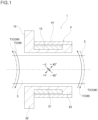
FIG. 1 is a cross-sectional view of a sensor portion of a torque measuring device according to a first example of an embodiment of the present disclosure. -
FIG. 2 is a perspective view of the sensor portion of the torque measuring device of the first example. -
FIG. 3A is a developed view of a flexible substrate of a coil unit of the torque measuring device of the first example, andFIG. 3B is a view of the flexible substrate viewed from below inFIG. 3A . -
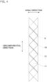
FIG. 4 is a developed view of a first detection coil, a second detection coil, a third detection coil, and a fourth detection coil of the coil unit of the torque measuring device of the first example, as viewed from the outside in the radial direction. -
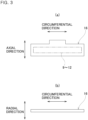
FIG. 5A to FIG. 5D are developed views of a first detection coil, a second detection coil, a third detection coil, and a fourth detection coil of the coil unit of the torque measuring device of the first example, and are developed views of each single unit viewed from the outside in the radial direction. -
FIG. 6 is a schematic circuit diagram of the torque measuring device of the first example. -
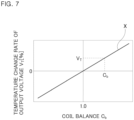
FIG. 7 is a graph illustrating a relationship between the coil balance Cb and the temperature change rate VT of the output voltage. -
FIG. 8 is a diagram illustrating a bridge circuit of a conventional torque measuring device. -
FIG. 9 is a perspective view of a rotating shaft for explaining the direction of stress generated when torque is applied to the rotating shaft. - A first example of an embodiment of the present disclosure will be described with reference to
FIGS. 1 to 7 . -
FIG. 1 andFIG. 2 are diagrams illustrating the structure of asensor portion 4 of atorque measuring device 1 of this example. Atorque measuring device 1 of this example is a device for measuring the torque transmitted by arotating shaft 2, and can be used by being incorporated in various mechanical devices. - Specific examples of a mechanical device in corporating the
torque measuring device 1 of the present example include: a mechanical device of a power train of an automobile, for example, a transmission such as an automatic transmission (AT), a belt-type continuously variable transmission, a toroidal type continuously variable transmission, an automatic manual transmission (AMT), a dual clutch transmission (DCT) or the like that performs gear shifting that is controlled on the vehicle side; or a transfer, a manual transmission (MT), or the like. The driving system of the target vehicle is not particularly limited and may be FF, FR, MR, RR, 4WD, or the like. - The driving system of the target vehicle is not particularly limited and may be FF, FR, MR, RR, 4WD, or the like. Specific examples of the other mechanical devices incorporating the
torque measuring device 1 of the present example include devices that change a rotation speed of a power shaft with gears such as a speed reducer or a speed increaser of a wind turbine, a railway vehicle, a rolling mill for steel, and the like. - In this example, the
rotating shaft 2 is a rotating shaft incorporated in a mechanical device of a power train as described above, and is rotatably supported by a rolling bearing (not illustrated) with respect to a casing (not illustrated) that does not rotate during use, and has a magnetostrictive effect section, the magnetic permeability of which changes according to torque to be transmitted. - The
rotating shaft 2 has anintermediate shaft portion 3 at an intermediate portion in the axial direction thereof as illustrated inFIG. 1 . An outer peripheral surface of theintermediate shaft portion 3 is configured by a cylindrical surface. In this example, theintermediate shaft portion 3 of therotating shaft 2 functions as a magnetostrictive effect section. For this reason, therotating shaft 2 is made of a magnetic metal. As the magnetic metal forming therotating shaft 2, various magnetic steels can be used such as carburized steel such as SCr420 and SCM420, and carbon steel such as S45C, which are defined in the Japanese Industrial Standards (JIS). - When a torque T is applied to the
rotating shaft 2, stresses σ with differing positive and negative signs act on the outer peripheral surface of theintermediate shaft portion 3 in directions inclined +45° and -45° with respect to the axial direction. Due to an inverse magnetostriction effect, the magnetic permeability increases in a direction in which the tensile stress (+σ) acts, and decreases in the direction in which the compressive stress (-σ) acts. - When carrying out the present disclosure, it is possible to improve the mechanical and magnetic properties of a portion of the outer peripheral surface of the
intermediate shaft portion 3 arranged at an inner side in the radial direction of thesensor portion 4 by subjecting the portion to a shot peening process to form a compression work hardened layer. In this way, sensitivity and hysteresis of torque measurement by thetorque measuring device 1 may be improved. - When carrying out the present disclosure, instead of having the
intermediate shaft portion 3 function as the magnetostrictive effect section, it is also possible to fix a magnetostrictive material functioning as the magnetostrictive effect section to an outer peripheral surface of theintermediate shaft portion 3. More specifically, an annular-shaped magnetostrictive material may be fitted around theintermediate shaft portion 3 and fixed, or a magnetostrictive material composed of a film coating such as plating or a film-like magnetostrictive material may be fixed to the outer peripheral surface of theintermediate shaft portion 3. - The
sensor portion 4 illustrated inFIG. 1 has an annular shape as a whole, and is supported and fixed to the casing while being arranged coaxially around theintermediate shaft portion 3. In this example, thesensor portion 4 includes acoil unit 13, aback yoke 14, and aholder 15. - In this example, the
coil unit 13 is formed into a cylindrical shape by a flexible substrate (FPC) 16 (seeFIG. 3A and FIG. 3B ) including a base film and printed wiring (conductors) held on the base film, and is arranged coaxially around theintermediate shaft portion 3 of therotating shaft 2. The flexible substrate (FPC) 16 has afirst detection coil 9, asecond detection coil 10, athird detection coil 11 and afourth detection coil 12 as illustrated inFIG. 4 andFIG. 5 . - More specifically, the
coil unit 13 is configured by rolling the band-shapedflexible substrate 16 into a cylindrical shape as illustrated inFIG. 3A and FIG. 3B , and joining both end portions in the length direction, for example, by bonding. - The
flexible substrate 16 has four wiring layers that are layered in the thickness direction, and thefirst detection coil 9, thesecond detection coil 10, thethird detection coil 11, and thefourth detection coil 12, each of which is configured by printed wiring, are arranged on these wiring layers. - In a state that the band-shaped
flexible substrate 16 is rolled into a cylindrical shape, that is, in a state that thecylindrical coil unit 13 is formed, the detection coils 9 to 12 are arranged in order of thefirst detection coil 9, thesecond detection coil 10, thefourth detection coil 12, and thethird detection coil 11 from the inner side in the radial direction. -
FIG. 4 illustrates a developed view of thefirst detection coil 9, thesecond detection coil 10, thethird detection coil 11, and thefourth detection coil 12 as seen from the outer side in the radial direction of thecoil unit 13.FIG. 5A to FIG. 5D illustrate developed views of the detection coils 9 to 12 in a single state as seen from the outside in the radial direction of thecoil unit 13. - The
first detection coil 9 is a detection coil for detecting a change in magnetic permeability on the outer peripheral surface of theintermediate shaft portion 3 in a direction inclined +45° with respect to the axial direction, or in other words, is a detection coil that changes its own inductance L1 as the magnetic permeability in that direction changes. - As illustrated in
FIG. 5A , thefirst detection coil 9 includes a plurality ofcoil pieces 17 arranged side by side at equal pitches in the circumferential direction. Thesecoil pieces 17 have a parallelogram shape when viewed from the radial direction, and include wiring that is inclined -45° with respect to the axial direction of theintermediate shaft portion 3.Coil pieces 17 that are adjacent in the circumferential direction are connected in series by a conductor such as printed wiring (not illustrated). - In
FIG. 5A , thecoil pieces 17 are schematically illustrated, and illustrated as if the entire circumference is connected; however, actually, discontinuous portions exist in a part of thecoil pieces 17 in the circumferential direction. Thecoil pieces 17 have two end portions that are separated across discontinuous portions.Coil pieces 17 that are adjacent in the circumferential direction are connected in series by connecting one end portion of each with a conductor such as printed wiring (not illustrated). These aspects are the same for thesecond detection coil 10 to thefourth detection coil 12 below. - The
second detection coil 10 is a detection coil for detecting a change in magnetic permeability on the outer peripheral surface of theintermediate shaft portion 3 in a direction inclined -45° with respect to the axial direction, or in other words, is a detection coil that changes its own inductance L2 as the magnetic permeability in that direction changes. - As illustrated in
FIG. 5B , thesecond detection coil 10 includes a plurality ofcoil pieces 18 arranged side by side at equal pitches in the circumferential direction. Thesecoil pieces 18 have a parallelogram shape when viewed from the radial direction, and include wiring that is inclined +45° with respect to the axial direction of theintermediate shaft portion 3.Coil pieces 18 that are adjacent in the circumferential direction are connected in series by a conductor such as printed wiring (not illustrated). - The
third detection coil 11 is a detection coil for detecting a change in magnetic permeability on the outer peripheral surface of theintermediate shaft portion 3 in a direction inclined +45° with respect to the axial direction, or in other words, is a detection coil that changes its own inductance L3 as the magnetic permeability in that direction changes. - As illustrated in
FIG. 5D , thethird detection coil 11 includes a plurality ofcoil pieces 19 arranged side by side at equal pitches in the circumferential direction. Thesecoil pieces 19 have a parallelogram shape when viewed from the radial direction, and include wiring that is inclined -45° with respect to the axial direction of theintermediate shaft portion 3.Coil pieces 19 that are adjacent in the circumferential direction are connected in series by a conductor such as printed wiring (not illustrated). - The
fourth detection coil 12 is a detection coil for detecting a change in magnetic permeability on the outer peripheral surface of theintermediate shaft portion 3 in a direction inclined -45° with respect to the axial direction, or in other words, is a detection coil that changes its own inductance L4 as the magnetic permeability in that direction changes. - As illustrated in
FIG. 5C , thefourth detection coil 12 includes a plurality ofcoil pieces 20 arranged side by side at equal pitches in the circumferential direction. Thesecoil pieces 20 have a parallelogram shape when viewed from the radial direction, and include wiring that is inclined +45° with respect to the axial direction of theintermediate shaft portion 3.Coil pieces 20 that are adjacent in the circumferential direction are connected in series by a conductor such as printed wiring (not illustrated). - However, when carrying out the present disclosure, configuration regarding the specific shape and arrangement of the first detection coil, the second detection coil, the third detection coil, and the fourth detection coil is not limited to the configuration of this example, and various conventionally known configurations may be adopted.
- The
back yoke 14 is a member that forms a magnetic path for magnetic fluxes generated by thefirst detection coil 9, thesecond detection coil 10, thethird detection coil 11, and thefourth detection coil 12. Theback yoke 14 is made of a magnetic material such as mild steel and is formed in a cylindrical shape as a whole. Theback yoke 14 is arranged coaxially around thecoil unit 13. - In this example, in this state, a clearance in the radial direction is provided along the axial direction between the
coil unit 13 and theback yoke 14. That is, an outer peripheral surface of thecoil unit 13 and an inner peripheral surface of theback yoke 14 are separated in the radial direction. - The
holder 15 is a member that holds thecoil unit 13 and theback yoke 14, and is made of a non-magnetic material and has an annular shape as a whole. - In this example, the
holder 15 has a cylindrical holdercylindrical portion 21, a first outward-facingflange 22 extending outward in the radial direction over the entire circumference from an end portion on one side in the axial direction (left side inFIG. 1 ) of the holdercylindrical portion 21, and a second outward-facing flange 23 extending outward in the radial direction over the entire circumference from an end portion on the other side in the axial direction (right side inFIG. 1 ) of the holdercylindrical portion 21. The outer diameter of the first outward-facingflange 22 is larger than the outer diameter of the second outward-facing flange 23. - The
holder 15 is supported and fixed to the casing while being arranged coaxially around theintermediate shaft portion 3. - In this example, the
coil unit 13 is fitted onto an intermediate portion in the axial direction of the holdercylindrical portion 21, that is, in a portion of the holdercylindrical portion 21 that is positioned in the axial direction between the first outward-facingflange 22 and the second outward-facing flange 23. An end surface of theback yoke 14 on the one side in the axial direction is in contact with an intermediate portion in the radial direction of a side surface on the other side in the axial direction of the first outward-facingflange 22, and an inner peripheral surface of an end portion on the other side in the axial direction of theback yoke 14 is fitted onto an outer peripheral surface of the second outward-facing flange 23 by an interference fit or the like. - Note that when carrying out the present disclosure, a configuration different from that of this example can be employed for the coil unit that includes the
first detection coil 9, thesecond detection coil 10, thethird detection coil 11, and thefourth detection coil 12; the back yoke arranged around the coil unit; the holder that holds the coil unit and back yoke; and the like. -
FIG. 6 is a schematic circuit diagram of thetorque measuring device 1 of the present example. Thetorque measuring device 1 of this example includes thesensor portion 4, anoscillator 5, avoltage measuring portion 6, and atorque calculating portion 7. In this example, of the elements of the schematic circuit configuration diagram illustrated inFIG. 6 , the elements other than the detection coils 9 to 12 are, for example, fixed to theflexible substrate 16 or fixed to another substrate (not illustrated), for example, a substrate installed on a side of a vehicle body. - In the
sensor portion 4, abridge circuit 8 is configured in which four detection coils, thefirst detection coil 9, thesecond detection coil 10, thethird detection coil 11, and thefourth detection coil 12, are arranged on four sides thereof. That is, thebridge circuit 8 has two end points, point A and point C, and two midpoints, point B and point D. - The
first detection coil 9 is arranged on the side between point D and point A. Thesecond detection coil 10 is arranged on the side between point A and point B. Thethird detection coil 11 is arranged on the side between point B and point C. Thefourth detection coil 12 is arranged on the side between point C and point D. - In the
bridge circuit 8, thefirst detection coil 9 and thethird detection coil 11, which are detection coils for detecting a change in magnetic permeability in a direction inclined +45° with respect to the axial direction, are arranged on the outer peripheral surface of theintermediate shaft portion 3 on a side between point D and point A and on a side between the point B and point C, which are opposite sides of one of the two pairs of opposite sides of the four sides. - Moreover, the
second detection coil 10 and thefourth detection coil 12, which are detection coils for detecting a change in magnetic permeability in a direction inclined -45° with respect to the axial direction, are arranged on the outer peripheral surface of theintermediate shaft portion 3 on a side between point A and point B and a side between point C and point D, which are opposite sides of the other pair of the two pairs of opposite sides. - The
oscillator 5 can apply an input voltage Vi, which is an AC voltage, between the two end points, point A and Point C, of thebridge circuit 8. - The
voltage measuring portion 6 can measure the output voltage Vo, which is the voltage between the two midpoints, point B and point D, of thebridge circuit 8. - That is, when using the
torque measuring device 1 of this example, theoscillator 5 applies an input voltage Vi between point A and point C, which are two end points of thebridge circuit 8, and causes alternating current to flow through thefirst detection coil 9, thesecond detection coil 10, thethird detection coil 11, and thefourth detection coil 12, and as a result, as indicated by arrows α1, α2, α3, and α4 inFIG. 5A to FIG. 5D , currents flow in mutually opposite directions between thecoil pieces first detection coil 9, thesecond detection coil 10, thethird detection coil 11, and thefourth detection coil 12. - In other words, pairs of
coil pieces first detection coil 9, thesecond detection coil 10, thethird detection coil 11, and thefourth detection coil 12, and part of the magnetic flux of this alternating magnetic field passes through a surface layer portion of theintermediate shaft portion 3. - In this state, when a torque T in a direction indicated by arrow CW in
FIG. 1 is applied to theintermediate shaft portion 3, a tensile stress (+σ) in the +45° direction with respect to the axial direction and a compressive stress (-σ) in the -45° direction with respect to the axial direction act on therotating shaft 2. Then, due to an inverse magnetostriction effect, the magnetic permeability of theintermediate shaft portion 3 increases in the +45° direction, which is the direction in which the tensile stress (+σ) acts, and the magnetic permeability of theintermediate shaft portion 3 decreases in the -45° direction, which is the direction in which the compressive stress (-σ) acts. - On the other hand, the
first detection coil 9 and thethird detection coil 11 are configured to include wiring inclined -45° with respect to the axial direction of theintermediate shaft portion 3, and part of the magnetic flux of the alternating magnetic field generated around the wiring passes through the surface layer of theintermediate shaft portion 3 in the +45° direction, which is the direction in which the magnetic permeability increases. Therefore, the inductances L1 and L3 of thefirst detection coil 9 and thethird detection coil 11 increase, respectively. - In addition, the
second detection coil 10 and thefourth detection coil 14 are configured to include wiring inclined +45° with respect to the axial direction of theintermediate shaft portion 3, and part of the magnetic flux of the alternating magnetic field generated around the wiring passes through the surface layer of theintermediate shaft portion 3 in the -45° direction, which is the direction in which the magnetic permeability decreases. Therefore, the inductances L2 and L4 of thesecond detection coil 10 and thefourth detection coil 12 decrease, respectively. - In contrast, when a torque T in the direction indicated by the arrow CCW in
FIG. 1 is applied to theintermediate shaft portion 3, by the action opposite to the case described above, the inductances L1 and L3 of thefirst detection coil 9 and thethird detection coil 11 decrease, and the inductances L2 and L4 of thesecond detection coil 10 and thefourth detection coil 12 increase. - In any case, in the
bridge circuit 8, an output voltage Vo corresponding to the direction and magnitude of the torque T applied to therotating shaft 2 is obtained as the voltage between the two midpoints, point B and point D. In this example, thevoltage measuring portion 6 is able to measure the output voltage Vo. - The
torque calculating portion 7 has a function of using the output voltage Vo measured by thevoltage measuring portion 6 to calculate the torque T applied to therotating shaft 2. - The
torque calculating portion 7 has a temperature measurement function of measuring a temperature of thesensor portion 4, and specifically, an amount of temperature change ΔT in thesensor portion 4 based on a preset reference temperature Ta. When carrying out the present disclosure, it is possible to adopt various conventionally known configurations as a configuration to achieve this temperature measurement function, and more specifically, it is possible to adopt a configuration that measures an amount of temperature change ΔT of thesensor portion 4 by processing an amount of current of theentire bridge circuit 8 by software (for example, refer toJP 2018-048956 A sensor portion 4. - Here, the reference temperature Ta can be set to any temperature, for example, normal room temperature (about 20°C).
- The
torque calculating portion 7 stores in advance a temperature change rate VT of the output voltage of thebridge circuit 8, which is a correction parameter. This temperature change rate VT is the rate of change of the output voltage due to the temperature change of thesensor portion 4, and more specifically, is a rate that indicates by what percentage the output voltage deviates each time the temperature of thesensor portion 4 changes by 1°C. - The
torque calculating portion 7 has a function of using the amount of temperature change ΔT of thesensor portion 4 measured by the temperature measurement function and the temperature change rate VT stored in advance to perform temperature correction of the output voltage Vo measured by thevoltage measurement unit 6. That is, in a case where the current temperature of thesensor portion 4 deviates from the reference temperature Ta by the amount of temperature change ΔT, thetorque calculating portion 7 has a function of correcting the amount of deviation (ΔV) in the output voltage of thebridge circuit 8 caused by this deviation. - For this reason, in this example, the
torque calculating portion 7 multiplies the amount of temperature change ΔT of thesensor portion 4 measured by the temperature measurement function by the temperature change rate VT, that is, ΔV=ΔT×VT to obtain the amount of temperature change of deviation (ΔV). Then, by subtracting the obtained amount of deviation (ΔV) from the output voltage Vo measured by thevoltage measuring portion 6, an output voltage Va (=Vo-ΔV) that is estimated to be measured in a case where the temperature of thesensor portion 4 is the reference temperature Ta is obtained. That is, thetorque calculating portion 7 corrects the output voltage Vo measured by thevoltage measuring portion 6 to the output voltage Va. - The
torque calculating portion 7 calculates the torque T applied to therotating shaft 2 based on the output voltage Va after temperature correction. That is, thetorque calculating portion 7 stores in advance a relationship Y between the output voltage of thebridge circuit 8 and the torque T at the reference temperature Ta. Thetorque calculating portion 7 uses the relationship Y to calculate the torque T from the output voltage Va after temperature correction. - As described above, in this example, the
torque calculating portion 7 performs temperature correction of the output voltage Vo of thebridge circuit 8, and since the torque T is calculated based on the output voltage Va after temperature correction, it is easy to ensure the measurement accuracy of the torque T regardless of temperature fluctuations of thesensor portion 4. - In addition to the configuration described above, the
torque measuring device 1 of this example includes arecording medium 24 recording the temperature change rate VT, which is obtained in the following manufacturing method of thetorque measuring device 1 of this example, is attached to an exterior of thesensor portion 4. Therecording medium 24 may be attached to any readable location on the exterior of thesensor portion 4, such as an outer circumferential surface of theback yoke 14 or a side surface in the axial direction of theholder 15. A manufacturing method of thetorque measuring device 1 of this example is described below. - The manufacturing method of the
torque measuring device 1 of this example includes a first step and a second step. - The first step is a step of obtaining a relationship X with regard to the
torque measuring device 1 to be manufactured, which is conceptually represented by a straight line inFIG. 7 , and more specifically, a step of acquiring a relationship between a coil balance Cb and the temperature change rate VT of the output voltage of thebridge circuit 8. - Here, the coil balance Cb is a ratio (R1×R3)/(R2×R4) of a product R1×R3 of resistance values R1 and R3 of two opposite sides forming one pair of opposite sides of the four sides of the
bridge circuit 8, and a product R2×R4 of resistance values R2 and R4 of two opposite sides forming another pair of opposite sides of the four sides. - That is, in the first step, a plurality (a large number) of test samples each having the same configuration as the
torque measuring device 1 to be manufactured and having different coil balances Cb are prepared. - The second step is a step is to find the temperature change rate VT for the
torque measuring device 1 to be manufactured. That is, in the second step, a measuring device such as an impedance analyzer is used to measure the resistance values of the four sides of thebridge circuit 8, that is, the respective resistance values R1, R2, R3, and R4 of thefirst detection coil 9, thesecond detection coil 10, thethird detection coil 11, and thefourth detection coil 12, for thetorque measuring device 1 to be manufactured. - Then, the coil balance Cb is obtained from the measured resistance values R1, R2, R3, and R4. Using the determined coil balance Cb, the temperature change rate VT corresponding to the coil balance Cb is determined from the relationship X in
FIG. 7 obtained in the first step. - Note that the relationship X in
FIG. 7 obtained in the first step can be shared for thesetorque measuring devices 1 when mass-producing thetorque measuring devices 1 to be manufactured. - The manufacturing method of the
torque measuring device 1 of this example further includes a third step. - The third step is a step of storing the temperature change rate VT obtained in the second step in the
torque calculating portion 7 of thetorque measuring device 1 to be manufactured. - When carrying out the present disclosure, the third step can be performed at a manufacturing plant of the
torque measuring device 1 or at manufacturing plant of an automobile in which thetorque measuring device 1 is to be installed. - In a case where the third step is performed at an automobile manufacturing plant, when shipping the
torque measuring device 1 from the manufacturing plant of thetorque measuring device 1 to the automobile manufacturing plant, for example, as indicated by solid or dashed lines inFIG. 2 , arecording medium 24 such as a two-dimensional bar code or an IC tag that records the temperature change rate VT obtained in the second step can be attached to a part of the exterior of thetorque measuring device 1. Then, when the automobile is manufactured, the temperature change rate VT recorded on therecording medium 24 is read, and the read temperature change rate VT is stored in thetorque calculating portion 7. - Note that in the example indicated by the solid line in
FIG. 2 , therecording medium 24 is attached to a part in the circumferential direction of the outer peripheral surface of theback yoke 14, which is a part of the exterior, and in the example indicated by the dashed line inFIG. 2 , therecording medium 24 is attached to a side surface in the axial direction of theholder 15, which is part of the exterior. However, the location where therecording medium 24 is attached to the exterior can be any location as long as the temperature change rate VT recorded on therecording medium 24 can be read. - According to the manufacturing method of the
torque measuring device 1 of this example, the manufacturing time can be reduced while at the same time thetorque measuring device 1 to be manufactured has a structure having a temperature correction function. - That is, in this example, of the first, second, and third steps included in the method of manufacturing the
torque measuring device 1, the first step, which takes a relatively long time, does not need to be performed individually for each of thetorque measuring devices 1 when mass-producing thetorque measuring devices 1 to be manufactured. In other words, the relationship X inFIG. 7 obtained in the first step can be shared by thesetorque measuring devices 1. - Then, in the second step, the temperature change rate VT is automatically found simply by finding the coil balance Cb from the resistance values R1, R2, R3, and R4.
-
- 1 Torque measuring device
- 2 Rotating shaft
- 3 Intermediate shaft portion
- 4 Sensor portion
- 5 Oscillator
- 6 Voltage measuring portion
- 7 Torque calculating portion
- 8 Bridge circuit
- 9 First detection coil
- 10 Second detection coil
- 11 Third detection coil
- 12 Fourth detection coil
- 13 Coil unit
- 14 Back yoke
- 15 Holder
- 16 Flexible substrate
- 17 Coil piece
- 18 Coil piece
- 19 Coil piece
- 20 Coil piece
- 21 Holder cylindrical portion
- 22 First outward-facing flange
- 23 Second outward-facing flange
- 24 Recording medium
- 100 Bridge circuit
- 101 Rotating shaft
- 102 Magnetostrictive effect section
- 103 First detection coil
- 104 Second detection coil
- 105 Third detection coil
- 106 Fourth detection coil
Claims (3)
- A manufacturing method of a torque measuring device, the torque measuring device comprising:a sensor portion having a bridge circuit in which four detection coils arranged around a magnetostrictive effect section of a rotating shaft are arranged on four sides;an oscillator configured to apply an input voltage to two end points of the bridge circuit;a voltage measuring portion configured to measure an output voltage that is a voltage between two midpoints of the bridge circuit; anda torque calculating portion configured to calculate torque applied to the rotating shaft using the output voltage measured by the voltage measuring portion;the torque calculating portion having a temperature measurement function that measures a temperature of the sensor portion; a function of performing temperature correction of the output voltage measured by the voltage measuring portion using the temperature of the sensor portion measured by the temperature measurement function, and a temperature change rate VT of the output voltage, which is a correction parameter stored in advance in the torque calculating portion; and a function of calculating torque applied to the rotating shaft based on an output voltage after the temperature correction; andthe manufacturing method of the torque measuring device comprising:a first step of performing testing of a plurality of test samples having the same configuration as the torque measuring device to be manufactured to find a coil balance Cb that is a ratio (R1×R3)/(R2×R4) of a product R1×R3 of resistance values R1 and R3 of two opposite sides forming one pair of opposite sides of the four sides, and a product R2×R4 of resistance values R2 and R4 of two opposite sides forming another pair of opposite sides of the four sides, and the temperature change rate VT, and acquiring a relationship X between the coil balance Cb and the temperature change rate VT from the test results; anda second step of measuring the resistance values R1, R2, R3, and R4 of each of the four sides to find the coil balance Cb for the torque measuring device to be manufactured, and using the found coil balance Cb to find the temperature change rate VT therefor from the relationship X acquired in the first step.
- The manufacturing method of a torque measuring device according to claim 1, further comprising a third step of storing the temperature change rate VT found in the second step in the torque calculating portion of the torque measuring device to be manufactured.
- A torque measuring device comprising:a sensor portion having a bridge circuit in which four detection coils arranged around a magnetostrictive effect section of a rotating shaft are arranged on four sides;an oscillator configured to apply an input voltage to two end points of the bridge circuit;a voltage measuring portion configured to measure an output voltage that is a voltage between two midpoints of the bridge circuit; anda torque calculating portion configured to calculate torque applied to the rotating shaft using the output voltage measured by the voltage measuring portion;the torque calculating portion having a temperature measurement function that measures a temperature of the sensor portion; a function of performing temperature correction of the output voltage measured by the voltage measuring portion using the temperature of the sensor portion measured by the temperature measurement function, and a temperature change rate VT of the output voltage, which is a correction parameter stored in advance in the torque calculating portion; and a function of calculating torque applied to the rotating shaft based on an output voltage after the temperature correction; anda recording medium on which the temperature change rate VT is recorded is attached to an exterior of the sensor portion.
Applications Claiming Priority (2)
| Application Number | Priority Date | Filing Date | Title |
|---|---|---|---|
| JP2022031028A JP7765989B2 (en) | 2022-03-01 | 2022-03-01 | Method for manufacturing a torque measuring device |
| PCT/JP2023/007093 WO2023167144A1 (en) | 2022-03-01 | 2023-02-27 | Torque measuring device, and method for manufacturing same |
Publications (2)
| Publication Number | Publication Date |
|---|---|
| EP4488643A1 true EP4488643A1 (en) | 2025-01-08 |
| EP4488643A4 EP4488643A4 (en) | 2026-03-11 |
Family
ID=87851348
Family Applications (1)
| Application Number | Title | Priority Date | Filing Date |
|---|---|---|---|
| EP23763402.7A Pending EP4488643A4 (en) | 2022-03-01 | 2023-02-27 | TORQUE MEASURING DEVICE AND METHOD FOR MANUFACTURING IT |
Country Status (5)
| Country | Link |
|---|---|
| US (1) | US12281952B2 (en) |
| EP (1) | EP4488643A4 (en) |
| JP (1) | JP7765989B2 (en) |
| CN (1) | CN118900991A (en) |
| WO (1) | WO2023167144A1 (en) |
Families Citing this family (2)
| Publication number | Priority date | Publication date | Assignee | Title |
|---|---|---|---|---|
| JP7805819B2 (en) * | 2022-03-01 | 2026-01-26 | 日本精工株式会社 | Torque Measuring Device |
| JP2025158365A (en) * | 2024-04-04 | 2025-10-17 | 日本精工株式会社 | Method for obtaining correction values for torque sensors and method for measuring torque on rotating shafts |
Family Cites Families (12)
| Publication number | Priority date | Publication date | Assignee | Title |
|---|---|---|---|---|
| US5307690A (en) * | 1991-07-29 | 1994-05-03 | Kubota Corporation | Temperature compensating device for torque measuring apparatus |
| JPH11125555A (en) * | 1997-08-21 | 1999-05-11 | Toshiba Tec Corp | Load cell scale |
| JP2003050167A (en) * | 2001-08-07 | 2003-02-21 | Showa Corp | Temperature-compensating apparatus for torque sensor |
| JP4243987B2 (en) * | 2003-07-10 | 2009-03-25 | 株式会社ショーワ | Torque sensor neutral voltage regulator |
| JP4257612B2 (en) * | 2005-06-06 | 2009-04-22 | ソニー株式会社 | Recording device and method for adjusting recording device |
| JP5753060B2 (en) * | 2011-11-07 | 2015-07-22 | ヤマハ発動機株式会社 | Linear conveyor and drive control method thereof |
| US9618408B2 (en) * | 2015-02-26 | 2017-04-11 | General Electric Company | System and method for torque transducer and temperature sensor |
| US9435708B1 (en) * | 2015-06-16 | 2016-09-06 | Magcanica, Inc. | Devices and methods to enhance accuracy of magnetoelastic torque sensors |
| JP6759925B2 (en) * | 2016-09-23 | 2020-09-23 | 日立金属株式会社 | Torque sensor and its correction method |
| US10345167B2 (en) * | 2017-07-12 | 2019-07-09 | General Electric Company | Temperature compensated torque sensor |
| CN107677416B (en) * | 2017-10-30 | 2023-11-03 | 山东中车同力达智能装备有限公司 | Straight-shaft transmission type torque wrench verification platform |
| JP7160005B2 (en) * | 2019-09-10 | 2022-10-25 | 日立金属株式会社 | Temperature detection circuit for magnetostrictive sensor, magnetostrictive sensor, and temperature detection method for magnetostrictive sensor |
-
2022
- 2022-03-01 JP JP2022031028A patent/JP7765989B2/en active Active
-
2023
- 2023-02-27 WO PCT/JP2023/007093 patent/WO2023167144A1/en not_active Ceased
- 2023-02-27 EP EP23763402.7A patent/EP4488643A4/en active Pending
- 2023-02-27 CN CN202380024294.9A patent/CN118900991A/en active Pending
- 2023-02-28 US US18/176,098 patent/US12281952B2/en active Active
Also Published As
| Publication number | Publication date |
|---|---|
| WO2023167144A1 (en) | 2023-09-07 |
| JP7765989B2 (en) | 2025-11-07 |
| JP2023127315A (en) | 2023-09-13 |
| CN118900991A (en) | 2024-11-05 |
| US12281952B2 (en) | 2025-04-22 |
| US20230280223A1 (en) | 2023-09-07 |
| EP4488643A4 (en) | 2026-03-11 |
Similar Documents
| Publication | Publication Date | Title |
|---|---|---|
| US12281952B2 (en) | Torque measuring device and manufacturing method thereof | |
| KR920006454B1 (en) | Magnetic elastic torque transducer, manufacturing method thereof and torque detecting method | |
| US9683906B2 (en) | Redundant torque sensor—multiple band arrays | |
| US11215523B2 (en) | Devices and methods to enhance accuracy of torque sensors | |
| EP2160582B1 (en) | Torque and load monitoring using magnetic sensor arrays | |
| US12385793B2 (en) | Torque measuring device | |
| US12449318B2 (en) | Torque measuring device | |
| US20230280222A1 (en) | Torque measuring device | |
| JP2009036312A (en) | Bearing device | |
| JP6956576B2 (en) | Torque load member and torque transmission device | |
| JPH0543991A (en) | Magnetic scale steel rod | |
| JPH0298640A (en) | magnetostrictive torque sensor | |
| US20250314541A1 (en) | Method for acquiring correction value for torque sensor, and method for measuring torque of rotating shaft | |
| Aldemir et al. | Design and Prototype Production of an Axial Displacement Measurement System by Using LVDT for Propeller Shaft Development Process | |
| JP6956575B2 (en) | Torque load member and torque transmission device | |
| JP2000337975A (en) | Thrust force detecting device, torque / thrust force detecting device, and detecting method | |
| JP2023127316A (en) | torque measuring device |
Legal Events
| Date | Code | Title | Description |
|---|---|---|---|
| STAA | Information on the status of an ep patent application or granted ep patent |
Free format text: STATUS: THE INTERNATIONAL PUBLICATION HAS BEEN MADE |
|
| PUAI | Public reference made under article 153(3) epc to a published international application that has entered the european phase |
Free format text: ORIGINAL CODE: 0009012 |
|
| STAA | Information on the status of an ep patent application or granted ep patent |
Free format text: STATUS: REQUEST FOR EXAMINATION WAS MADE |
|
| 17P | Request for examination filed |
Effective date: 20240919 |
|
| AK | Designated contracting states |
Kind code of ref document: A1 Designated state(s): AL AT BE BG CH CY CZ DE DK EE ES FI FR GB GR HR HU IE IS IT LI LT LU LV MC ME MK MT NL NO PL PT RO RS SE SI SK SM TR |
|
| DAV | Request for validation of the european patent (deleted) | ||
| DAX | Request for extension of the european patent (deleted) | ||
| A4 | Supplementary search report drawn up and despatched |
Effective date: 20260205 |
|
| RIC1 | Information provided on ipc code assigned before grant |
Ipc: G01L 3/10 20060101AFI20260130BHEP Ipc: G01L 25/00 20060101ALI20260130BHEP |