EP4488642A1 - Torque measurement device - Google Patents
Torque measurement device Download PDFInfo
- Publication number
- EP4488642A1 EP4488642A1 EP23763401.9A EP23763401A EP4488642A1 EP 4488642 A1 EP4488642 A1 EP 4488642A1 EP 23763401 A EP23763401 A EP 23763401A EP 4488642 A1 EP4488642 A1 EP 4488642A1
- Authority
- EP
- European Patent Office
- Prior art keywords
- casing
- peripheral surface
- holder
- coil
- torque
- Prior art date
- Legal status (The legal status is an assumption and is not a legal conclusion. Google has not performed a legal analysis and makes no representation as to the accuracy of the status listed.)
- Pending
Links
Images




Classifications
-
- G—PHYSICS
- G01—MEASURING; TESTING
- G01L—MEASURING FORCE, STRESS, TORQUE, WORK, MECHANICAL POWER, MECHANICAL EFFICIENCY, OR FLUID PRESSURE
- G01L3/00—Measuring torque, work, mechanical power, or mechanical efficiency, in general
- G01L3/02—Rotary-transmission dynamometers
- G01L3/04—Rotary-transmission dynamometers wherein the torque-transmitting element comprises a torsionally-flexible shaft
- G01L3/10—Rotary-transmission dynamometers wherein the torque-transmitting element comprises a torsionally-flexible shaft involving electric or magnetic means for indicating
- G01L3/101—Rotary-transmission dynamometers wherein the torque-transmitting element comprises a torsionally-flexible shaft involving electric or magnetic means for indicating involving magnetic or electromagnetic means
- G01L3/102—Rotary-transmission dynamometers wherein the torque-transmitting element comprises a torsionally-flexible shaft involving electric or magnetic means for indicating involving magnetic or electromagnetic means involving magnetostrictive means
-
- G—PHYSICS
- G01—MEASURING; TESTING
- G01L—MEASURING FORCE, STRESS, TORQUE, WORK, MECHANICAL POWER, MECHANICAL EFFICIENCY, OR FLUID PRESSURE
- G01L1/00—Measuring force or stress, in general
- G01L1/12—Measuring force or stress, in general by measuring variations in the magnetic properties of materials resulting from the application of stress
- G01L1/125—Measuring force or stress, in general by measuring variations in the magnetic properties of materials resulting from the application of stress by using magnetostrictive means
-
- G—PHYSICS
- G01—MEASURING; TESTING
- G01L—MEASURING FORCE, STRESS, TORQUE, WORK, MECHANICAL POWER, MECHANICAL EFFICIENCY, OR FLUID PRESSURE
- G01L3/00—Measuring torque, work, mechanical power, or mechanical efficiency, in general
- G01L3/02—Rotary-transmission dynamometers
- G01L3/04—Rotary-transmission dynamometers wherein the torque-transmitting element comprises a torsionally-flexible shaft
- G01L3/10—Rotary-transmission dynamometers wherein the torque-transmitting element comprises a torsionally-flexible shaft involving electric or magnetic means for indicating
- G01L3/101—Rotary-transmission dynamometers wherein the torque-transmitting element comprises a torsionally-flexible shaft involving electric or magnetic means for indicating involving magnetic or electromagnetic means
- G01L3/105—Rotary-transmission dynamometers wherein the torque-transmitting element comprises a torsionally-flexible shaft involving electric or magnetic means for indicating involving magnetic or electromagnetic means involving inductive means
-
- G—PHYSICS
- G01—MEASURING; TESTING
- G01L—MEASURING FORCE, STRESS, TORQUE, WORK, MECHANICAL POWER, MECHANICAL EFFICIENCY, OR FLUID PRESSURE
- G01L5/00—Apparatus for, or methods of, measuring force, work, mechanical power, or torque, specially adapted for specific purposes
- G01L5/13—Apparatus for, or methods of, measuring force, work, mechanical power, or torque, specially adapted for specific purposes for measuring the tractive or propulsive power of vehicles
- G01L5/136—Force sensors associated with a vehicle traction coupling
Definitions
- the present disclosure relates to a torque measuring device capable of measuring torque.
- a magnetostrictive torque measuring method is known as a method for measuring torque transmitted by a rotating shaft.
- a magnetostrictive effect section is provided at a portion in the axial direction of a rotating shaft, and a torque sensor for detecting a change in magnetic permeability of the magnetostrictive effect section is arranged near the magnetostrictive effect section.
- the magnetic permeability of the magnetostrictive effect section changes based on an inverse magnetostrictive effect.
- an output signal of the torque sensor changes in accordance with the change in magnetic permeability of the magnetostrictive effect section, and thus torque transmitted by the rotating shaft can be measured.
- JP 2016-200552 A and JP 2017-049124 A describe a specific structure of a magnetostrictive torque sensor.
- the torque sensors described in these publications include a coil unit and a back yoke.
- the coil unit has a cylindrical shape and is arranged around the magnetostrictive effect section of the rotating shaft.
- the coil unit has a detection coil that changes voltage in response to changes in magnetic permeability of the magnetostrictive effect section.
- the back yoke is a member that serves as a magnetic path for a magnetic field generated by the detection coil, is made of a magnetic material and has a cylindrical shape, and is arranged around the coil unit.
- the torque transmitted by the rotating shaft can be measured based on the voltage of the detection coil.
- the back yoke is arranged around the coil unit, leakage of magnetic flux to the outside is suppressed, an effect of disturbance becomes less likely, and accuracy of torque measurement can be improved.
- the coil unit which is formed in a cylindrical shape using a flexible substrate, is directly adhered to the inner peripheral surface of the back yoke, there is a possibility that during assembly work, the coil unit may collide with surrounding objects and be damaged before being adhered.
- the torque sensor supported by the support member during use includes a back yoke as a single component that only serves as a magnetic path, the number of parts increases, which causes an increase in manufacturing cost.
- An object of the present disclosure is to provide a torque measuring device in which a coil unit is less likely to be damaged during assembly work and in which the number of parts can be reduced.
- the torque measuring device includes a casing, a rotating shaft, and a torque sensor.
- the casing is made of magnetic metal.
- the rotating shaft is rotatably arranged inside the casing, and has a magnetostrictive effect section whose magnetic permeability changes according to torque to be transmitted.
- the torque sensor is arranged around the magnetostrictive effect section and supported by the casing.
- the torque sensor includes a coil unit formed in a cylindrical shape using a flexible substrate having a detection coil that changes voltage in response to changes in the magnetic permeability of the magnetostrictive effect section, and a holder made of rubber or synthetic resin that covers an outer peripheral surface of the coil unit and having portions that protrude toward both sides in the axial direction than the coil unit.
- the torque sensor in a state with an outer peripheral surface of the holder fitted into an inner peripheral surface of the casing, is supported by the casing.
- the holder includes portions that cover side surfaces on both side in the axial direction of the coil unit.
- the coil unit is entirely embedded in the holder.
- a ridge provided on the outer peripheral surface of the holder is engaged with a circumferential groove provided on the inner peripheral surface of the casing.
- an outward facing flange portion provided on the holder abuts against a side surface in the axial direction of the casing.
- a portion of the casing is sandwiched from both sides in the axial direction by two outward facing flange portions provided on the holder.
- the holder is abutted against a stepped surface facing in the axial direction and provided on the inner peripheral surface of the casing.
- the holder is sandwiched from both sides in the axial direction between a stepped surface facing in the axial direction provided on the inner peripheral surface of the casing and an inward facing flange portion provided on the casing.
- the coil unit is less likely to be damaged during assembly work, and the number of parts can be reduced.
- FIGS. 1 to 6 A first example of an embodiment of the present disclosure will be described with reference to FIGS. 1 to 6 .
- a torque measuring device 1 of this example includes a casing 2, a rotating shaft 3, and a torque sensor 4.
- the torque measuring device 1 is capable of measuring torque transmitted by the rotating shaft 3, and is applicable to various mechanical devices.
- Specific examples of applicable mechanical devices include: a mechanical device of a power train of an automobile, for example, a transmission such as an automatic transmission (AT), a belt-type continuously variable transmission, a toroidal type continuously variable transmission, an automatic manual transmission (AMT), a dual clutch transmission (DCT) and the like that performs gear shifting that is controlled on the vehicle side; or a transfer, a manual transmission (MT), or the like.
- the driving system of the target vehicle is not particularly limited and may be FF, FR, MR, RR, 4WD, or the like.
- Specific examples of the other mechanical device incorporating the torque measuring device 1 of the present example include devices that change a rotation speed of a power shaft with gears such as a speed reducer or a speed increaser of a wind turbine, a railway vehicle, a rolling mill for steel, and the like.
- the casing 2 is an exterior member such as a casing, housing, cover, etc. of a mechanical device that constitutes the power train of an automobile, and is made of magnetic metal such as iron alloy.
- the casing 2 has a tubular portion 5 having a cylindrical shape as illustrated in FIG. 1 .
- the rotating shaft 3 is a torque transmission shaft of a mechanical device that constitutes the power train of an automobile, and has a magnetostrictive effect section whose magnetic permeability changes according to the torque to be transmitted.
- the rotating shaft 3 is rotatably supported by a rolling bearing (not illustrated) at a portion (not illustrated) of the casing 2.
- the rotating shaft 3 has an intermediate shaft portion 6 arranged coaxially with the tubular portion 5 inside the tubular portion 5 of the casing 2.
- An outer peripheral surface of the intermediate shaft portion 6 is configured by a cylindrical surface.
- the intermediate shaft portion 6 of the rotating shaft 3 functions as the magnetostrictive effect section.
- the rotating shaft 3 is made of magnetic metal.
- various magnetic steels can be used such as carburized steel such as SCr420 and SCM420, and carbon steel such as S45C, which are defined in the Japanese Industrial Standards (JIS).
- the intermediate shaft portion 6 When a torque is applied to the rotating shaft 3 and the intermediate shaft portion 6 is torsionally deformed, the intermediate shaft portion 6 is subjected to a stress corresponding to the torque, that is, a tensile stress acts in the +45° direction with respect to the axial direction and a compressive stress acts in the -45° direction with respect to the axial direction. As this occurs, the magnetic permeability in each direction of the intermediate shaft portion 6 changes due to an inverse magnetostriction effect.
- an annular-shaped magnetostrictive material may be externally fitted around the intermediate shaft portion 6 and fixed, or a magnetostrictive material composed of a film coating such as plating or a film-like magnetostrictive material may be externally fixed to the outer peripheral surface of the intermediate shaft portion 6.
- the torque sensor 4 has a cylindrical shape as a whole, is arranged around the intermediate shaft portion 6 of the rotating shaft 3, and is internally fitted and supported by the tubular portion 5 of the casing 2.
- the torque sensor 4 includes a coil unit 7 and a holder 8.
- the torque sensor 4 does not include a back yoke.
- the coil unit 7 is configured by a flexible substrate (FPC) 10 including a base film and printed wiring (conductors) held by the base film.
- the flexible substrate 10 has a detection coil 9 that changes voltage in response to changes in magnetic permeability of the intermediate shaft portion 6.
- the coil unit 7 is formed by rolling the band-shaped flexible substrate 10 as illustrated in FIG. 2 into a cylindrical shape, and by bonding together, for example, both end portions in the length direction of the flexible substrate 10.
- the detection coil 9 includes a first split coil 11, a second split coil 12, a third split coil 13, and a fourth split coil 14 provided on the flexible substrate 10. That is, the flexible substrate 10 has four wiring layers that are layered in the substrate thickness direction, and the first split coil 11, the second split coil 12, the third split coil 132, and the fourth split coil 14, each of which is configured by printed wiring, are arranged on these wiring layers.
- the first split coil 11, the second split coil 12, the third split coil 13, and the fourth split coil 14 are arranged in order from the inner side in the radial direction.
- FIG. 3 is a developed view of the detection coil 9 as viewed from the outside in the radial direction of the coil unit 7.
- FIG. 4A to FIG. 4D are developed views of the first split coil 11, the second split coil 12, the third split coil 13, and the fourth split coil 14 of the detection coil 9 as seen from the outside in the radial direction of the coil unit 7.
- the first split coil 11 includes a plurality of coil pieces 15 arranged side by side at equal pitches in a circumferential direction. These coil pieces 15 have a parallelogram shape when viewed from the radial direction, and include wiring that is inclined +45° with respect to the axial direction of the intermediate shaft portion 6. Coil pieces 15 that are adjacent in the circumferential direction are connected in series by a conductor such as printed wiring (not illustrated).
- the coil pieces 15 are schematically illustrated, and illustrated as if the entire circumference is connected; however, actually, discontinuous portions exist in a part of the coil pieces 15 in the circumferential direction.
- the coil pieces 15 have two end portions that are separated across the discontinuous portion.
- Coil pieces 15 that are adjacent in the circumferential direction are connected in series by connecting one end of each with a conductor such as printed wiring (not illustrated). These aspects are the same for the second split coil 12 to the fourth split coil 14 below.
- the second split coil 12 includes a plurality of coil pieces 16 arranged side by side at equal pitches in the circumferential direction. These coil pieces 16 have a parallelogram shape when viewed from the radial direction, and include wiring that is inclined -45° with respect to the axial direction of the intermediate shaft portion 6. Coil pieces 16 that are adjacent in the circumferential direction are connected in series by a conductor such as printed wiring (not illustrated).
- the third split coil 13 includes a plurality of coil pieces 17 arranged side by side at equal pitches in the circumferential direction. These coil pieces 17 have a parallelogram shape when viewed from the radial direction, and include wiring that is inclined -45° with respect to the axial direction of the intermediate shaft portion 6. Coil pieces 17 that are adjacent in the circumferential direction are connected in series by a conductor such as printed wiring (not illustrated).
- the fourth split coil 14 includes a plurality of coil pieces 18 arranged side by side at equal pitches in the circumferential direction. These coil pieces 18 have a parallelogram shape when viewed from the radial direction, and include wiring that is inclined +45° with respect to the axial direction of the intermediate shaft portion 6. Coil pieces 18 that are adjacent in the circumferential direction are connected in series by a conductor such as printed wiring (not illustrated).
- configuration regarding the specific shape and arrangement of the first split coil, second split coil, third split coil, and fourth split coil that constitute the detection coil is not limited to the configuration of this example, and various conventionally known configurations may be adopted.
- the holder 8 is made of rubber or synthetic resin, covers an outer peripheral surface of the coil unit 7, and has portions that protrude from the coil unit 7 on both sides in the axial direction.
- the holder 8 also covers side surfaces on both sides in the axial direction and the inner peripheral surface of the coil unit 7. That is, in this example, the holder 8 is configured in a cylindrical shape as a whole, and by entirely embedding the coil unit 7 arranged coaxially with the holder 8, the holder 8 covers the outer peripheral surface, the side surfaces on both sides in the axial direction, and the inner peripheral surface of the coil unit 7.
- the torque sensor 4 is fixed to and supported by the casing 2 by fitting the outer peripheral surface of the holder 8 into the inner peripheral surface of the tubular portion 5 of the casing 2 with an interference fit.
- the coil unit 7 is arranged coaxially around the intermediate shaft portion 6 of the rotating shaft 3.
- the outer peripheral surface of the holder 8 can also be adhesively fixed to the inner peripheral surface of the tubular portion 5 of the casing 2.
- the torque sensor 4 of this example further includes an electronic circuit 19 as illustrated in FIG. 5 .
- the electronic circuit 19 includes the first split coil 11, the second split coil 12, the third split coil 13, and the fourth split coil 14 of the detection coil 9 (see FIG. 3 ), and generates an output voltage corresponding to the voltage of the detection coil 9.
- the electronic circuit 19 includes a bridge circuit in which the first split coil 11, the second split coil 12, the third split coil 13, and the fourth split coil 14 are arranged on four sides of the bridge circuit.
- components other than the detection coil 9 may be fixed to the flexible substrate 10 or another substrate (not illustrated), for example.
- an AC voltage is applied between the points A and B of the electronic circuit 19 by the oscillator 20, causing an alternating current to flow through the first split coil 11, the second split coil 12, the third split coil 13, and the fourth split coil 14. Then, as indicated by arrows ⁇ 1, ⁇ 2, ⁇ 3, and ⁇ 4 in FIG. 4A to FIG. 4D , in the first split coil 11, the second split coil 12, the third split coil 13, and the fourth split coil 14, currents flow in mutually opposite directions between the coil pieces 15, 16, 17, and 18 adjacent in the circumferential direction.
- pairs of coil pieces 15, 16, 17, and 18 adjacent in the circumferential direction are connected to each other so that the current flows in such directions.
- an alternating magnetic field is generated around the first split coil 11, the second split coil 12, the third split coil 13, and the fourth split coil 14, and part of the magnetic flux of this alternating magnetic field passes through a surface layer portion of the intermediate shaft portion 6.
- the first split coil 11 and the fourth split coil 14 are configured to include wiring inclined +45° with respect to the axial direction of the intermediate shaft portion 6, and part of the magnetic flux of the alternating magnetic field generated around the wiring passes through the surface layer of the intermediate shaft portion 6 in the -45° direction, which is the direction in which the magnetic permeability decreases. Therefore, the inductances of the first split coil 11 and the fourth split coil 14 decrease.
- the second split coil 12 and the third split coil 13 are configured to include wiring inclined -45° with respect to the axial direction of the intermediate shaft portion 6, and part of the magnetic flux of the alternating magnetic field generated around the wiring passes through the surface layer of the intermediate shaft portion 6 in the +45° direction, which is the direction in which the magnetic permeability increases. Therefore, the inductances of the third split coil 13 and the fourth split coil 14 increase.
- the lock-in amplifier 21 detects and amplifies the midpoint voltage, which is the potential difference between the points C and D, and as a result, an output voltage V corresponding to the direction and magnitude of the torque T applied to the rotating shaft 3 is obtained. Therefore, the torque transmitted by the rotating shaft 3 can be measured by using this output voltage V
- the tubular portion 5 forming the casing 2 made of magnetic metal arranged around the coil unit 7 functions as a back yoke.
- leakage of magnetic flux to the outside is suppressed, the effect of disturbance is reduced, and accuracy of torque measurement can be improved.
- each component of the torque measuring device 1 expands or contracts due to temperature changes during use. Accordingly, a clearance C in the radial direction existing between the outer peripheral surface of the coil unit 7 and the inner peripheral surface of the tubular portion 5 that functions as the back yoke changes, and as a result the output voltage V of the electronic circuit 19 changes.
- FIG. 6 is a graph conceptually illustrating a relationship between the clearance C in the radial direction and the output voltage V of the electronic circuit 19 in the torque measuring device 1 of this example. Note that the graph illustrated in FIG. 6 , including the numerical values on the horizontal axis, is an example. The graph illustrated in FIG. 6 can be obtained based on simulation analysis or experimentation.
- the change in the output voltage V of the electronic circuit 19 is non-linear, that is, non-linear change with respect to the change in the clearance C in the radial direction that accompanies temperature changes during use.
- the change in the output voltage V of the electronic circuit 19 is linear, that is, the change is linear with respect to the change in the clearance C in the radial direction due to the change in temperature during use.
- the change range ⁇ X of the clearance C in the radial direction due to temperature changes during use is regulated so as to fall within the range X1 in which the change in the output voltage V of the electronic circuit 19 is linear change with respect to the change in the clearance C in the radial direction. More specifically, the clearance C in the radial direction at room temperature is set so that the change range ⁇ X falls within the range X1 (0.2 mm to 0.8 mm in the illustrated example).
- the holder 8 covers the outer peripheral surface of the coil unit 7 and includes a portion that protrudes further to both sides in the axial direction than the coil unit 7. More specifically, in this example, the outer peripheral surface and the side surfaces of both sides in the axial direction of the coil unit 7 are covered by the holder 8. Therefore, it is possible to prevent the outer peripheral surface and the side surfaces in the axial direction of the coil unit 7 from directly colliding with surrounding objects and being damaged when performing work of assembling the coil unit 7 in the casing or the like.
- the inner peripheral surface of the coil unit 7 is also covered by the holder 8, the inner peripheral surface of the coil unit 7 can be prevented from directly colliding surrounding objects and being damaged during assembly work.
- the torque sensor 4 Since the tubular portion 5 of the casing 2 can function as a back yoke, the torque sensor 4 does not have a separate back yoke as a separate component. Therefore, the number of parts can be reduced accordingly.
- the change range ⁇ X of the clearance C in the radial direction due to the temperature change during use is regulated so that the change of the output voltage V of the electronic circuit 19 with respect to the change of the clearance C in the radial direction falls within the range X1 where the change is linear, and thus, the change in the output voltage V of the electronic circuit 19 due to the change in temperature during use can be easily corrected using the separately detected temperature.
- the clearance C in the radial direction can also be set so that the change range ⁇ X overlaps the range X2 or X3.
- the output voltage V of the electronic circuit 19 can be corrected by a correction circuit configured in consideration of nonlinearity in the range X2 or X3.
- a holder 8a of a torque sensor 4 covers only an outer peripheral surface and both side surfaces in the axial direction of a coil unit 7, and does not cover an inner peripheral surface of the coil unit 7. Therefore, a volume of the holder 8a can be reduced accordingly, and material cost of the holder 8a can be suppressed.
- FIG. 8 A third example of an embodiment of the present disclosure will be described with reference to FIG. 8 .
- a tubular portion 5a of a casing 2 includes a circumferential groove 22 extending over the entire circumference of an inner peripheral surface of the tubular portion 5a.
- a size of the circumferential groove 22 is about the same size as a locking groove for locking an O-ring.
- a holder 8b of a torque sensor 4 is made of rubber and has a ridge 23 protruding outward in the radial direction over the entire circumference from a central portion in the axial direction.
- the torque sensor 4 is positioned in the axial direction with respect to the tubular portion 5a by engaging the ridge 23 with the circumferential groove 22.
- the ridge 23 is passed in the axial direction through a portion of the inner peripheral surface of the tubular portion 5a that is positioned between the opening portion and the circumferential groove 22 while being elastically reduced in diameter.
- Other configurations and effects are the same as those of the first example.
- the circumferential groove 22 and the ridge 23 that engage with each other are arranged closer to an opening portion of the tubular portion 5a than in the third example.
- the circumferential groove 22 and the ridge 23 that engage with each other are arranged farther from the opening portion of the tubular portion 5a than in the third example.
- the distance that the torque sensor 4 is moved in the axial direction may be shortened while the diameter of the ridge 23 is elastically reduced.
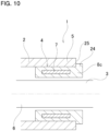
- a holder 8c has an outward facing flange portion 24 protruding outward in a radial direction from an end portion on one side in the axial direction (the right side in FIG. 10 ) over the entire circumference.
- the outward facing flange portion 24 is brought into contact with a side surface 25 in the axial direction of the tubular portion 5, which positions a torque sensor 4 in the axial direction with respect to the tubular portion 5.
- Other configurations and effects are the same as those of the first example.
- a tubular portion 5b of a casing 2 has a convex portion 26 protruding inward in the radial direction from an intermediate portion in the axial direction over the entire circumference of the tubular portion 5b.
- a holder 8d is made of rubber and has two outward facing flange portions 24 protruding outward in the radial direction from both end portions in the axial direction over the entire circumference of the holder 8d.
- one of the two outward facing flange portions 24 is elastically reduced in diameter and is passed in the axial direction through the inner side in the radial direction of the convex portion 26.
- Other configurations and effects are the same as those of the first example.
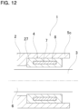
- a tubular portion 5c of a casing 2 has a stepped surface 27 facing a torque sensor 4 side in the axial direction at a portion of an inner peripheral surface of the tubular portion 5c adjacent to the torque sensor 4 at a side far from an opening portion of the tubular portion 5c.
- the torque sensor 4 is positioned in the axial direction with respect to the tubular portion 5c by bringing the holder 8 in contact with the stepped surface 27.
- Other configurations and effects are the same as those of the first example.
- a seventh example of an embodiment of the present disclosure will be described with reference to FIG. 13 .
- a tubular portion 5d of a casing 2 has an annular inward facing flange portion 28 bent inward in the radial direction at an end portion on an opening side in the axial direction.
- a torque sensor 4 is sandwiched from both sides in the axial direction between a stepped surface 27 of the tubular portion 5d and the inward facing flange portion 28. This positions the torque sensor 4 in the axial direction with respect to the tubular portion 5b and prevents the torque sensor 4 from slipping in the axial direction out from inside the tubular portion 5d.
- the inward facing flange portion 28 may be formed by inserting the torque sensor 4 inside the tubular portion 5d before the inward facing flange portion 28 is formed, and then plastically deforming the end portion on the opening side of the tubular portion 5d inward in the radial direction as indicated by the arrow in FIG. 13 .
- Other configurations and effects are the same as those of the sixth example.
Landscapes
- Physics & Mathematics (AREA)
- General Physics & Mathematics (AREA)
- Chemical & Material Sciences (AREA)
- Electromagnetism (AREA)
- Analytical Chemistry (AREA)
- Engineering & Computer Science (AREA)
- Combustion & Propulsion (AREA)
- Power Steering Mechanism (AREA)
Abstract
Description
- The present disclosure relates to a torque measuring device capable of measuring torque.
- In recent years, in the field of automobiles, the development of systems that measure torque transmitted by a rotating shaft of a power train, or in other words, a power transmission mechanism, use the measurement results to control output of an engine or an electric motor that is a power source, and execute speed change control of a transmission is advancing.
- Conventionally, a magnetostrictive torque measuring method is known as a method for measuring torque transmitted by a rotating shaft. In the magnetostrictive torque measuring method, a magnetostrictive effect section is provided at a portion in the axial direction of a rotating shaft, and a torque sensor for detecting a change in magnetic permeability of the magnetostrictive effect section is arranged near the magnetostrictive effect section. When torque is applied to the rotating shaft and elastic torsional deformation occurs in the magnetostrictive effect section, the magnetic permeability of the magnetostrictive effect section changes based on an inverse magnetostrictive effect. As a result, an output signal of the torque sensor changes in accordance with the change in magnetic permeability of the magnetostrictive effect section, and thus torque transmitted by the rotating shaft can be measured.
- For example,
JP 2016-200552 A JP 2017-049124 A - The coil unit has a cylindrical shape and is arranged around the magnetostrictive effect section of the rotating shaft. The coil unit has a detection coil that changes voltage in response to changes in magnetic permeability of the magnetostrictive effect section. The back yoke is a member that serves as a magnetic path for a magnetic field generated by the detection coil, is made of a magnetic material and has a cylindrical shape, and is arranged around the coil unit.
- With a torque sensor having such a configuration, the torque transmitted by the rotating shaft can be measured based on the voltage of the detection coil. In addition, since the back yoke is arranged around the coil unit, leakage of magnetic flux to the outside is suppressed, an effect of disturbance becomes less likely, and accuracy of torque measurement can be improved.
-
JP 2016-200552 A - In recent years, in order to reduce the thickness of a magnetostrictive torque sensor, it has been considered to form a cylindrical coil unit from a flexible substrate having a detection coil. In such a torque sensor as well, arranging the back yoke around the coil unit is effective from the aspect of improving accuracy of torque measurement.
- However, when a configuration is adopted in which the coil unit, which is formed in a cylindrical shape using a flexible substrate, is directly adhered to the inner peripheral surface of the back yoke, there is a possibility that during assembly work, the coil unit may collide with surrounding objects and be damaged before being adhered.
- In addition, when the torque sensor supported by the support member during use includes a back yoke as a single component that only serves as a magnetic path, the number of parts increases, which causes an increase in manufacturing cost.
- An object of the present disclosure is to provide a torque measuring device in which a coil unit is less likely to be damaged during assembly work and in which the number of parts can be reduced.
- The torque measuring device according to an aspect of the present disclosure includes a casing, a rotating shaft, and a torque sensor.
- The casing is made of magnetic metal.
- The rotating shaft is rotatably arranged inside the casing, and has a magnetostrictive effect section whose magnetic permeability changes according to torque to be transmitted.
- The torque sensor is arranged around the magnetostrictive effect section and supported by the casing.
- The torque sensor includes a coil unit formed in a cylindrical shape using a flexible substrate having a detection coil that changes voltage in response to changes in the magnetic permeability of the magnetostrictive effect section, and a holder made of rubber or synthetic resin that covers an outer peripheral surface of the coil unit and having portions that protrude toward both sides in the axial direction than the coil unit.
- The torque sensor, in a state with an outer peripheral surface of the holder fitted into an inner peripheral surface of the casing, is supported by the casing.
- In the torque measuring device according to an aspect of the present disclosure, the holder includes portions that cover side surfaces on both side in the axial direction of the coil unit.
- In the torque measuring device according to an aspect of the present disclosure, the coil unit is entirely embedded in the holder.
- In the torque measuring device according to an aspect of the present disclosure, a ridge provided on the outer peripheral surface of the holder is engaged with a circumferential groove provided on the inner peripheral surface of the casing.
- In the torque measuring device according to an aspect of the present disclosure, an outward facing flange portion provided on the holder abuts against a side surface in the axial direction of the casing.
- In the torque measuring device according to an aspect of the present disclosure, a portion of the casing is sandwiched from both sides in the axial direction by two outward facing flange portions provided on the holder.
- In the torque measuring device according to an aspect of the present disclosure, the holder is abutted against a stepped surface facing in the axial direction and provided on the inner peripheral surface of the casing.
- In the torque measuring device according to an aspect of the present disclosure, the holder is sandwiched from both sides in the axial direction between a stepped surface facing in the axial direction provided on the inner peripheral surface of the casing and an inward facing flange portion provided on the casing.
- With the torque measuring device according to an aspect of the present disclosure, the coil unit is less likely to be damaged during assembly work, and the number of parts can be reduced.
-
-
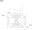
FIG. 1 is a cross-sectional view of a torque measuring device according to a first example of an embodiment of the present disclosure. -
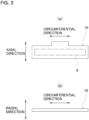
FIG. 2A is a developed view of a flexible substrate of a coil unit of the first example; andFIG.2B is a view as seen from below the flexible substrate inFIG. 2A . -
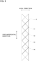
FIG. 3 is a developed view of a detection coil of the coil unit of the first example as seen from outside in a radial direction. -
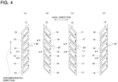
FIG. 4A to FIG. 4D illustrate a first split coil, a second split coil, a third split coil, and a fourth split coil of the detection coil of the coil unit of the first example, and are developed views of each single unit viewed from the outside in the radial direction. -
FIG. 5 is a diagram illustrating an electronic circuit of the first example. -
FIG. 6 is a graph conceptually illustrating a relationship between a radial clearance C between the coil unit and a back yoke and an output voltage V of the electronic circuit in the torque measuring device of the first example. -
FIG. 7 is a cross-sectional view of a torque measuring device according to a second example of an embodiment of the present disclosure. -
FIG. 8 is a cross-sectional view of a torque measuring device according to a third example of an embodiment of the present disclosure. -
FIG. 9A and FIG. 9B are half cross-sectional views of a torque measuring device, each illustrating a modification of the third example. -
FIG. 10 is a cross-sectional view of a torque measuring device according to a fourth example of an of the present disclosure. -
FIG. 11 is a cross-sectional view of a torque measuring device according to a fifth example of an embodiment of the present disclosure. -
FIG. 12 is a cross-sectional view of a torque measuring device according to a sixth example of an embodiment of the present disclosure. -
FIG. 13 is a cross-sectional view of a torque measuring device according to a seventh example of an embodiment of the present disclosure. - A first example of an embodiment of the present disclosure will be described with reference to
FIGS. 1 to 6 . - A
torque measuring device 1 of this example includes acasing 2, arotating shaft 3, and atorque sensor 4. Thetorque measuring device 1 is capable of measuring torque transmitted by therotating shaft 3, and is applicable to various mechanical devices. Specific examples of applicable mechanical devices include: a mechanical device of a power train of an automobile, for example, a transmission such as an automatic transmission (AT), a belt-type continuously variable transmission, a toroidal type continuously variable transmission, an automatic manual transmission (AMT), a dual clutch transmission (DCT) and the like that performs gear shifting that is controlled on the vehicle side; or a transfer, a manual transmission (MT), or the like. The driving system of the target vehicle is not particularly limited and may be FF, FR, MR, RR, 4WD, or the like. - Specific examples of the other mechanical device incorporating the
torque measuring device 1 of the present example include devices that change a rotation speed of a power shaft with gears such as a speed reducer or a speed increaser of a wind turbine, a railway vehicle, a rolling mill for steel, and the like. - In the
torque measuring device 1 of this example, thecasing 2 is an exterior member such as a casing, housing, cover, etc. of a mechanical device that constitutes the power train of an automobile, and is made of magnetic metal such as iron alloy. In this example, thecasing 2 has atubular portion 5 having a cylindrical shape as illustrated inFIG. 1 . - In this example, the
rotating shaft 3 is a torque transmission shaft of a mechanical device that constitutes the power train of an automobile, and has a magnetostrictive effect section whose magnetic permeability changes according to the torque to be transmitted. Therotating shaft 3 is rotatably supported by a rolling bearing (not illustrated) at a portion (not illustrated) of thecasing 2. - The
rotating shaft 3 has anintermediate shaft portion 6 arranged coaxially with thetubular portion 5 inside thetubular portion 5 of thecasing 2. An outer peripheral surface of theintermediate shaft portion 6 is configured by a cylindrical surface. In the present example, theintermediate shaft portion 6 of therotating shaft 3 functions as the magnetostrictive effect section. For this reason, therotating shaft 3 is made of magnetic metal. As the magnetic metal forming therotating shaft 3, various magnetic steels can be used such as carburized steel such as SCr420 and SCM420, and carbon steel such as S45C, which are defined in the Japanese Industrial Standards (JIS). - When a torque is applied to the
rotating shaft 3 and theintermediate shaft portion 6 is torsionally deformed, theintermediate shaft portion 6 is subjected to a stress corresponding to the torque, that is, a tensile stress acts in the +45° direction with respect to the axial direction and a compressive stress acts in the -45° direction with respect to the axial direction. As this occurs, the magnetic permeability in each direction of theintermediate shaft portion 6 changes due to an inverse magnetostriction effect. - When carrying out the present disclosure, it is possible to improve the mechanical and magnetic properties of a portion of the outer peripheral surface of the
intermediate shaft portion 6 that faces thetorque sensor 4 by subjecting the portion to a shot peening process to form a compression work hardened layer. In this way, sensitivity and hysteresis of torque measurement by thetorque measuring device 1 may be improved. - When carrying out the present disclosure, instead of having the
intermediate shaft portion 6 function as the magnetostrictive effect section, it is also possible to fix a magnetostrictive material functioning as the magnetostrictive effect section to an outer peripheral surface of theintermediate shaft portion 6. More specifically, an annular-shaped magnetostrictive material may be externally fitted around theintermediate shaft portion 6 and fixed, or a magnetostrictive material composed of a film coating such as plating or a film-like magnetostrictive material may be externally fixed to the outer peripheral surface of theintermediate shaft portion 6. - In this example, the
torque sensor 4 has a cylindrical shape as a whole, is arranged around theintermediate shaft portion 6 of therotating shaft 3, and is internally fitted and supported by thetubular portion 5 of thecasing 2. Thetorque sensor 4 includes acoil unit 7 and aholder 8. Thetorque sensor 4 does not include a back yoke. - The
coil unit 7 is configured by a flexible substrate (FPC) 10 including a base film and printed wiring (conductors) held by the base film. Theflexible substrate 10 has adetection coil 9 that changes voltage in response to changes in magnetic permeability of theintermediate shaft portion 6. - More specifically, in this example, the
coil unit 7 is formed by rolling the band-shapedflexible substrate 10 as illustrated inFIG. 2 into a cylindrical shape, and by bonding together, for example, both end portions in the length direction of theflexible substrate 10. - In this example, the
detection coil 9 includes afirst split coil 11, asecond split coil 12, athird split coil 13, and afourth split coil 14 provided on theflexible substrate 10. That is, theflexible substrate 10 has four wiring layers that are layered in the substrate thickness direction, and thefirst split coil 11, thesecond split coil 12, the third split coil 132, and thefourth split coil 14, each of which is configured by printed wiring, are arranged on these wiring layers. - In a state in which the band-shaped
flexible substrate 10 is rolled into a cylindrical shape, that is, in a state that thecylindrical coil unit 7 is formed, thefirst split coil 11, thesecond split coil 12, thethird split coil 13, and thefourth split coil 14 are arranged in order from the inner side in the radial direction. -
FIG. 3 is a developed view of thedetection coil 9 as viewed from the outside in the radial direction of thecoil unit 7.FIG. 4A to FIG. 4D are developed views of thefirst split coil 11, thesecond split coil 12, thethird split coil 13, and thefourth split coil 14 of thedetection coil 9 as seen from the outside in the radial direction of thecoil unit 7. - As illustrated in
FIG. 4A , thefirst split coil 11 includes a plurality ofcoil pieces 15 arranged side by side at equal pitches in a circumferential direction. Thesecoil pieces 15 have a parallelogram shape when viewed from the radial direction, and include wiring that is inclined +45° with respect to the axial direction of theintermediate shaft portion 6.Coil pieces 15 that are adjacent in the circumferential direction are connected in series by a conductor such as printed wiring (not illustrated). - In
FIG. 4A , thecoil pieces 15 are schematically illustrated, and illustrated as if the entire circumference is connected; however, actually, discontinuous portions exist in a part of thecoil pieces 15 in the circumferential direction. Thecoil pieces 15 have two end portions that are separated across the discontinuous portion.Coil pieces 15 that are adjacent in the circumferential direction are connected in series by connecting one end of each with a conductor such as printed wiring (not illustrated). These aspects are the same for thesecond split coil 12 to thefourth split coil 14 below. - As illustrated in
FIG. 4B , thesecond split coil 12 includes a plurality ofcoil pieces 16 arranged side by side at equal pitches in the circumferential direction. Thesecoil pieces 16 have a parallelogram shape when viewed from the radial direction, and include wiring that is inclined -45° with respect to the axial direction of theintermediate shaft portion 6.Coil pieces 16 that are adjacent in the circumferential direction are connected in series by a conductor such as printed wiring (not illustrated). - As illustrated in
FIG. 4C , thethird split coil 13 includes a plurality ofcoil pieces 17 arranged side by side at equal pitches in the circumferential direction. Thesecoil pieces 17 have a parallelogram shape when viewed from the radial direction, and include wiring that is inclined -45° with respect to the axial direction of theintermediate shaft portion 6.Coil pieces 17 that are adjacent in the circumferential direction are connected in series by a conductor such as printed wiring (not illustrated). - As illustrated in
FIG. 4D , thefourth split coil 14 includes a plurality ofcoil pieces 18 arranged side by side at equal pitches in the circumferential direction. Thesecoil pieces 18 have a parallelogram shape when viewed from the radial direction, and include wiring that is inclined +45° with respect to the axial direction of theintermediate shaft portion 6.Coil pieces 18 that are adjacent in the circumferential direction are connected in series by a conductor such as printed wiring (not illustrated). - When carrying out the present disclosure, configuration regarding the specific shape and arrangement of the first split coil, second split coil, third split coil, and fourth split coil that constitute the detection coil is not limited to the configuration of this example, and various conventionally known configurations may be adopted.
- The
holder 8 is made of rubber or synthetic resin, covers an outer peripheral surface of thecoil unit 7, and has portions that protrude from thecoil unit 7 on both sides in the axial direction. In this example, theholder 8 also covers side surfaces on both sides in the axial direction and the inner peripheral surface of thecoil unit 7. That is, in this example, theholder 8 is configured in a cylindrical shape as a whole, and by entirely embedding thecoil unit 7 arranged coaxially with theholder 8, theholder 8 covers the outer peripheral surface, the side surfaces on both sides in the axial direction, and the inner peripheral surface of thecoil unit 7. - Note that when carrying out the present disclosure, it is also possible to employ construction in which portions of the
holder 8 that cover the side surfaces on both sides in the axial direction of thecoil unit 7 are omitted. That is, a configuration may also be adopted in which theholder 8 is separated into a portion of theholder 8 positioned on the outer side in the radial direction of the outer peripheral surface of thecoil unit 7 and a portion of theholder 8 positioned on the inner side in the radial direction of the inner peripheral surface of thecoil unit 7. - The
torque sensor 4 is fixed to and supported by thecasing 2 by fitting the outer peripheral surface of theholder 8 into the inner peripheral surface of thetubular portion 5 of thecasing 2 with an interference fit. In this state, thecoil unit 7 is arranged coaxially around theintermediate shaft portion 6 of therotating shaft 3. When carrying out the present disclosure, the outer peripheral surface of theholder 8 can also be adhesively fixed to the inner peripheral surface of thetubular portion 5 of thecasing 2. - The
torque sensor 4 of this example further includes anelectronic circuit 19 as illustrated inFIG. 5 . Theelectronic circuit 19 includes thefirst split coil 11, thesecond split coil 12, thethird split coil 13, and thefourth split coil 14 of the detection coil 9 (seeFIG. 3 ), and generates an output voltage corresponding to the voltage of thedetection coil 9. - In this example, the
electronic circuit 19 includes a bridge circuit in which thefirst split coil 11, thesecond split coil 12, thethird split coil 13, and thefourth split coil 14 are arranged on four sides of the bridge circuit. Theelectronic circuit 19, in addition to thefirst split coil 11, thesecond split coil 12, thethird split coil 13, and thefourth split coil 14, includes anoscillator 20 for applying an AC voltage between a point A and a point B, and a lock-inamplifier 19 for detecting and amplifying a midpoint voltage (differential voltage) that is a potential difference between a point C and point D. - Of the components of the
electronic circuit 19, components other than thedetection coil 9 may be fixed to theflexible substrate 10 or another substrate (not illustrated), for example. - When the
torque measuring device 1 of this example is used, an AC voltage is applied between the points A and B of theelectronic circuit 19 by theoscillator 20, causing an alternating current to flow through thefirst split coil 11, thesecond split coil 12, thethird split coil 13, and thefourth split coil 14. Then, as indicated by arrows α1, α2, α3, and α4 inFIG. 4A to FIG. 4D , in thefirst split coil 11, thesecond split coil 12, thethird split coil 13, and thefourth split coil 14, currents flow in mutually opposite directions between thecoil pieces - In other words, pairs of
coil pieces first split coil 11, thesecond split coil 12, thethird split coil 13, and thefourth split coil 14, and part of the magnetic flux of this alternating magnetic field passes through a surface layer portion of theintermediate shaft portion 6. - In this state, when a torque T in a direction indicated by arrow CW in
FIG. 1 is applied to theintermediate shaft portion 6, a tensile stress (+σ) in a +45° direction with respect to the axial direction and a compressive stress (-σ) in a -45° direction with respect to the axial direction act on therotating shaft 3. Then, due to an inverse magnetostriction effect, the magnetic permeability of theintermediate shaft portion 6 increases in the +45° direction, which is the direction in which the tensile stress (+σ) acts, and the magnetic permeability of theintermediate shaft portion 6 decreases in the -45° direction, which is the direction in which the compressive stress (-σ) acts. - On the other hand, the
first split coil 11 and thefourth split coil 14 are configured to include wiring inclined +45° with respect to the axial direction of theintermediate shaft portion 6, and part of the magnetic flux of the alternating magnetic field generated around the wiring passes through the surface layer of theintermediate shaft portion 6 in the -45° direction, which is the direction in which the magnetic permeability decreases. Therefore, the inductances of thefirst split coil 11 and thefourth split coil 14 decrease. - Moreover, the
second split coil 12 and thethird split coil 13 are configured to include wiring inclined -45° with respect to the axial direction of theintermediate shaft portion 6, and part of the magnetic flux of the alternating magnetic field generated around the wiring passes through the surface layer of theintermediate shaft portion 6 in the +45° direction, which is the direction in which the magnetic permeability increases. Therefore, the inductances of thethird split coil 13 and thefourth split coil 14 increase. - In contrast, when a torque T is applied to the
intermediate shaft portion 6 in a direction indicated by arrow CCW inFIG. 1 , due to action opposite to the case described above, the inductances of thefirst split coil 11 and thefourth split coil 14 increase, and the inductances of thesecond split coil 12 and thethird split coil 13 decrease. - In either case, in the
electronic circuit 19, the lock-inamplifier 21 detects and amplifies the midpoint voltage, which is the potential difference between the points C and D, and as a result, an output voltage V corresponding to the direction and magnitude of the torque T applied to therotating shaft 3 is obtained. Therefore, the torque transmitted by therotating shaft 3 can be measured by using this output voltage V - In this example, when torque is measured as described above, the
tubular portion 5 forming thecasing 2 made of magnetic metal arranged around thecoil unit 7 functions as a back yoke. As a result, leakage of magnetic flux to the outside is suppressed, the effect of disturbance is reduced, and accuracy of torque measurement can be improved. - In the
torque measuring device 1 of this example, each component of thetorque measuring device 1 expands or contracts due to temperature changes during use. Accordingly, a clearance C in the radial direction existing between the outer peripheral surface of thecoil unit 7 and the inner peripheral surface of thetubular portion 5 that functions as the back yoke changes, and as a result the output voltage V of theelectronic circuit 19 changes. -
FIG. 6 is a graph conceptually illustrating a relationship between the clearance C in the radial direction and the output voltage V of theelectronic circuit 19 in thetorque measuring device 1 of this example. Note that the graph illustrated inFIG. 6 , including the numerical values on the horizontal axis, is an example. The graph illustrated inFIG. 6 can be obtained based on simulation analysis or experimentation. - As illustrated in this graph, in the range of clearance C in the radial direction, there is a range X1 in which linearity is indicated between the change in the clearance C in the radial direction and the change in the output voltage V of the
electronic circuit 19, and on both sides of the range X1, there are ranges X2, X3 in which non-linearity is exhibited between the change in the clearance C in the radial direction and the change in the output voltage V of theelectronic circuit 19. - That is, in the range X2 in which the clearance C in the radial direction is smaller than a predetermined value, or in the range X3 in which the clearance C in the radial direction is larger than a predetermined value, the change in the output voltage V of the
electronic circuit 19 is non-linear, that is, non-linear change with respect to the change in the clearance C in the radial direction that accompanies temperature changes during use. - On the other hand, in the intermediate range X1 sandwiched between the range X2 and the range X3, the change in the output voltage V of the
electronic circuit 19 is linear, that is, the change is linear with respect to the change in the clearance C in the radial direction due to the change in temperature during use. - Therefore, in the
torque measuring device 1 of this example, the change range ΔX of the clearance C in the radial direction due to temperature changes during use is regulated so as to fall within the range X1 in which the change in the output voltage V of theelectronic circuit 19 is linear change with respect to the change in the clearance C in the radial direction. More specifically, the clearance C in the radial direction at room temperature is set so that the change range ΔX falls within the range X1 (0.2 mm to 0.8 mm in the illustrated example). - According to the
torque measuring device 1 of this example, the following effects can be obtained. - In this example, the
holder 8 covers the outer peripheral surface of thecoil unit 7 and includes a portion that protrudes further to both sides in the axial direction than thecoil unit 7. More specifically, in this example, the outer peripheral surface and the side surfaces of both sides in the axial direction of thecoil unit 7 are covered by theholder 8. Therefore, it is possible to prevent the outer peripheral surface and the side surfaces in the axial direction of thecoil unit 7 from directly colliding with surrounding objects and being damaged when performing work of assembling thecoil unit 7 in the casing or the like. - Furthermore, in this example, since the inner peripheral surface of the
coil unit 7 is also covered by theholder 8, the inner peripheral surface of thecoil unit 7 can be prevented from directly colliding surrounding objects and being damaged during assembly work. - Since the
tubular portion 5 of thecasing 2 can function as a back yoke, thetorque sensor 4 does not have a separate back yoke as a separate component. Therefore, the number of parts can be reduced accordingly. - The change range ΔX of the clearance C in the radial direction due to the temperature change during use is regulated so that the change of the output voltage V of the
electronic circuit 19 with respect to the change of the clearance C in the radial direction falls within the range X1 where the change is linear, and thus, the change in the output voltage V of theelectronic circuit 19 due to the change in temperature during use can be easily corrected using the separately detected temperature. - However, when carrying out the present disclosure, the clearance C in the radial direction can also be set so that the change range ΔX overlaps the range X2 or X3. In this case, the output voltage V of the
electronic circuit 19 can be corrected by a correction circuit configured in consideration of nonlinearity in the range X2 or X3. - A second example of an embodiment of the present disclosure will be described with reference to
FIG. 7 . - In this example, a
holder 8a of atorque sensor 4 covers only an outer peripheral surface and both side surfaces in the axial direction of acoil unit 7, and does not cover an inner peripheral surface of thecoil unit 7. Therefore, a volume of theholder 8a can be reduced accordingly, and material cost of theholder 8a can be suppressed. - In addition, since the inner peripheral surface of the
coil unit 7 can be brought closer to an outer peripheral surface of anintermediate shaft portion 6, torque detection accuracy can be improved. Other configurations and effects are the same as those of the first example. - Note that when carrying out the present disclosure, as the holder, it is also possible to employ construction in which portions of the
holder 8a that cover the side surfaces on both sides in the axial direction of thecoil unit 7 are omitted. - A third example of an embodiment of the present disclosure will be described with reference to
FIG. 8 . - In this example, a
tubular portion 5a of acasing 2 includes acircumferential groove 22 extending over the entire circumference of an inner peripheral surface of thetubular portion 5a. In this example, a size of thecircumferential groove 22 is about the same size as a locking groove for locking an O-ring. Aholder 8b of atorque sensor 4 is made of rubber and has aridge 23 protruding outward in the radial direction over the entire circumference from a central portion in the axial direction. - In this example, in a state in which an outer peripheral surface of the
holder 8b is fitted into the inner peripheral surface of thetubular portion 5a, thetorque sensor 4 is positioned in the axial direction with respect to thetubular portion 5a by engaging theridge 23 with thecircumferential groove 22. - Note that in order to fit the outer peripheral surface of the
holder 8b into the inner peripheral surface of thetubular portion 5a, when inserting thetorque sensor 4 inside thetubular portion 5a through an opening portion of thetubular portion 5a, that is, an opening portion on the right side inFIG. 8 , theridge 23 is passed in the axial direction through a portion of the inner peripheral surface of thetubular portion 5a that is positioned between the opening portion and thecircumferential groove 22 while being elastically reduced in diameter. Other configurations and effects are the same as those of the first example. - When carrying out the present disclosure, it is also possible to adopt a configuration as illustrated in
FIG. 9A or FIG. 9B as a modification of the third example. - In the modification illustrated in
FIG. 9A , thecircumferential groove 22 and theridge 23 that engage with each other are arranged closer to an opening portion of thetubular portion 5a than in the third example. In the modification illustrated inFIG. 9B , thecircumferential groove 22 and theridge 23 that engage with each other are arranged farther from the opening portion of thetubular portion 5a than in the third example. In particular, with the configuration of the modification illustrated inFIG. 9A , when the outer peripheral surface of theholder 8b is fitted into the inner peripheral surface of thetubular portion 5a, the distance that thetorque sensor 4 is moved in the axial direction may be shortened while the diameter of theridge 23 is elastically reduced. - A fourth example of an embodiment of the present disclosure will be described with reference to
FIG. 10 . - In this example, a
holder 8c has an outward facingflange portion 24 protruding outward in a radial direction from an end portion on one side in the axial direction (the right side inFIG. 10 ) over the entire circumference. In this example, in a state that an outer peripheral surface of theholder 8c is fitted into an inner peripheral surface of atubular portion 5, the outward facingflange portion 24 is brought into contact with aside surface 25 in the axial direction of thetubular portion 5, which positions atorque sensor 4 in the axial direction with respect to thetubular portion 5. Other configurations and effects are the same as those of the first example. - A fifth example of an embodiment of the present disclosure will be described with reference to
FIG. 11 . - In this example, a
tubular portion 5b of acasing 2 has aconvex portion 26 protruding inward in the radial direction from an intermediate portion in the axial direction over the entire circumference of thetubular portion 5b. Aholder 8d is made of rubber and has two outward facingflange portions 24 protruding outward in the radial direction from both end portions in the axial direction over the entire circumference of theholder 8d. - In this example, in a state that an outer peripheral surface of the
holder 8d is fitted into an inner peripheral surface of theconvex portion 26, theconvex portion 26 is sandwiched from both sides in the axial direction by the two outward facingflange portions 24. This positions thetorque sensor 4 in the axial direction with respect to thetubular portion 5b and prevents thetorque sensor 4 from slipping in the axial direction out of thetubular portion 5b. - Note that when performing the work of fitting the
holder 8d into the inner peripheral surface of theconvex portion 26, one of the two outward facingflange portions 24 is elastically reduced in diameter and is passed in the axial direction through the inner side in the radial direction of theconvex portion 26. Other configurations and effects are the same as those of the first example. - A sixth example of an embodiment of the present disclosure will be described with reference to
FIG. 12 . - In this example, a
tubular portion 5c of acasing 2 has a steppedsurface 27 facing atorque sensor 4 side in the axial direction at a portion of an inner peripheral surface of thetubular portion 5c adjacent to thetorque sensor 4 at a side far from an opening portion of thetubular portion 5c. In a state that an outer peripheral surface of aholder 8 is fitted into the inner peripheral surface of thetubular portion 5c, thetorque sensor 4 is positioned in the axial direction with respect to thetubular portion 5c by bringing theholder 8 in contact with the steppedsurface 27. Other configurations and effects are the same as those of the first example. - A seventh example of an embodiment of the present disclosure will be described with reference to
FIG. 13 . - In this example, a
tubular portion 5d of acasing 2 has an annular inward facingflange portion 28 bent inward in the radial direction at an end portion on an opening side in the axial direction. In this example, atorque sensor 4 is sandwiched from both sides in the axial direction between a steppedsurface 27 of thetubular portion 5d and the inward facingflange portion 28. This positions thetorque sensor 4 in the axial direction with respect to thetubular portion 5b and prevents thetorque sensor 4 from slipping in the axial direction out from inside thetubular portion 5d. - Note that the inward facing
flange portion 28 may be formed by inserting thetorque sensor 4 inside thetubular portion 5d before the inward facingflange portion 28 is formed, and then plastically deforming the end portion on the opening side of thetubular portion 5d inward in the radial direction as indicated by the arrow inFIG. 13 . Other configurations and effects are the same as those of the sixth example. - The construction in the embodiments described above can be implemented in combination as appropriate within a range that does not cause contradiction.
-
- 1 Torque measuring device
- 2 Casing
- 3 Rotating shaft
- 4 Torque sensor
- 5, 5a, 5b, 5c, 5d Tubular portion
- 6 Intermediate shaft portion
- 7 Coil unit
- 8, 8a, 8b, 8c, 8d Holder
- 9 Detection coil
- 10 Flexible substrate
- 11 First split coil
- 12 Second split coil
- 13 Third split coil
- 14 Fourth split coil
- 15 Coil piece
- 16 Coil piece
- 17 Coil piece
- 18 Coil piece
- 19 Electronic circuit
- 20 Oscillator
- 21 Lock-in amplifier
- 22 Circumferential groove
- 23 Ridge
- 24 Outward facing flange portion
- 25 Side surface in the axial direction
- 26 Convex portion
- 27 Stepped surface
- 28 Inward facing flange portion
Claims (8)
- A torque measuring device comprising:a casing made of a magnetic metal;a rotating shaft rotatably arranged at an inner side of the casing and having a magnetostrictive effect section whose magnetic permeability changes according to torque to be transmitted; anda torque sensor arranged around the magnetostrictive effect section and supported by the casing;the torque sensor comprising: a coil unit formed in a cylindrical shape using a flexible substrate having a detection coil that changes voltage in response to changes in the magnetic permeability of the magnetostrictive effect section, and a holder made of rubber or synthetic resin, covering an outer peripheral surface of the coil unit, and having a portion that protrudes from the coil unit on both sides in an axial direction; andthe torque sensor supported by the casing with an outer peripheral surface of the holder fitted into an inner peripheral surface of the casing.
- The torque measuring device according to claim 1, wherein the holder includes portions covering sides surfaces on both sides in the axial direction of the coil unit.
- The torque measuring device according to claim 1 or 2, wherein the coil unit is entirely embedded in the holder.
- The torque measuring device according to any one of claims 1 to 3, wherein a ridge provided on the outer peripheral surface of the holder is engaged with a circumferential groove provided on the inner peripheral surface of the casing.
- The torque measuring device according to any one of claims 1 to 3, wherein an outward facing flange portion provided on the holder abuts against a side surface in the axial direction of the casing.
- The torque measuring device according to any one of claims 1 to 3, wherein a portion of the casing is sandwiched from both sides in the axial direction by two outward facing flange portions provided on the holder.
- The torque measuring device according to any one of claims 1 to 3, wherein the holder abuts against a stepped surface facing in the axial direction and provided on the inner peripheral surface of the casing.
- The torque measuring device according to any one of claims 1 to 3, wherein the holder is sandwiched from both sides in the axial direction between a stepped surface facing in the axial direction and provided on the inner peripheral surface of the casing and an inward facing flange portion provided on the casing.
Applications Claiming Priority (2)
| Application Number | Priority Date | Filing Date | Title |
|---|---|---|---|
| JP2022031027A JP2023127314A (en) | 2022-03-01 | 2022-03-01 | torque measuring device |
| PCT/JP2023/007092 WO2023167143A1 (en) | 2022-03-01 | 2023-02-27 | Torque measurement device |
Publications (2)
| Publication Number | Publication Date |
|---|---|
| EP4488642A1 true EP4488642A1 (en) | 2025-01-08 |
| EP4488642A4 EP4488642A4 (en) | 2026-03-25 |
Family
ID=87851342
Family Applications (1)
| Application Number | Title | Priority Date | Filing Date |
|---|---|---|---|
| EP23763401.9A Pending EP4488642A4 (en) | 2022-03-01 | 2023-02-27 | TORQUE MEASURING DEVICE |
Country Status (5)
| Country | Link |
|---|---|
| US (1) | US12449318B2 (en) |
| EP (1) | EP4488642A4 (en) |
| JP (1) | JP2023127314A (en) |
| CN (1) | CN118891501A (en) |
| WO (1) | WO2023167143A1 (en) |
Families Citing this family (1)
| Publication number | Priority date | Publication date | Assignee | Title |
|---|---|---|---|---|
| JP7805819B2 (en) * | 2022-03-01 | 2026-01-26 | 日本精工株式会社 | Torque Measuring Device |
Family Cites Families (20)
| Publication number | Priority date | Publication date | Assignee | Title |
|---|---|---|---|---|
| JPH0295228A (en) * | 1988-09-30 | 1990-04-06 | Matsushita Electric Ind Co Ltd | torque sensor |
| JPH0460431A (en) * | 1990-06-29 | 1992-02-26 | Mitsubishi Electric Corp | Strain detector |
| JPH0462444A (en) * | 1990-06-30 | 1992-02-27 | Nippon Densan Corp | Torque transducer |
| JP2811980B2 (en) * | 1991-03-04 | 1998-10-15 | 松下電器産業株式会社 | Torque sensor |
| JPH05203505A (en) * | 1992-01-27 | 1993-08-10 | Mitsubishi Electric Corp | Strain detector |
| JPH0783769A (en) * | 1993-09-17 | 1995-03-31 | Matsushita Electric Ind Co Ltd | Torque sensor and manufacturing method thereof |
| JPH085477A (en) * | 1994-06-16 | 1996-01-12 | Unisia Jecs Corp | Magnetostrictive torque sensor |
| JP3673932B2 (en) * | 1995-08-09 | 2005-07-20 | 光洋電子工業株式会社 | Torque detection device |
| JPH11132877A (en) * | 1997-08-27 | 1999-05-21 | Toyota Autom Loom Works Ltd | Torque sensor and stator |
| SE517710C2 (en) * | 1999-12-14 | 2002-07-09 | Abb Ab | Magnetostrictive sensor for measuring torque and use of the sensor |
| US6925893B2 (en) * | 2002-09-17 | 2005-08-09 | The Furukawa Electric Co., Ltd. | Rotation sensor |
| JP2004184187A (en) * | 2002-12-02 | 2004-07-02 | Yamaha Motor Co Ltd | Magnetostrictive torque sensor |
| JP2004245619A (en) * | 2003-02-12 | 2004-09-02 | Yaskawa Electric Corp | Magnetostrictive strain sensor |
| JP4292967B2 (en) * | 2003-12-05 | 2009-07-08 | 日立電線株式会社 | Magnetostrictive torque sensor |
| US7454998B1 (en) * | 2006-07-25 | 2008-11-25 | Chih-Ching Hsieh | Socket assembly |
| JP5509143B2 (en) * | 2011-04-27 | 2014-06-04 | 日立オートモティブシステムズステアリング株式会社 | Power steering device and method of assembling power steering device |
| JP6376028B2 (en) | 2015-04-14 | 2018-08-22 | 日立金属株式会社 | Torque sensor |
| JP6555023B2 (en) * | 2015-09-02 | 2019-08-07 | 日立金属株式会社 | Torque sensor |
| JP2024501962A (en) * | 2020-12-30 | 2024-01-17 | アボット ダイアベティス ケア インコーポレイテッド | Device for analyte monitoring |
| US20240230574A1 (en) * | 2021-01-15 | 2024-07-11 | Dwyer Instruments, Llc | Humidity sensor with improved contaminant sealing |
-
2022
- 2022-03-01 JP JP2022031027A patent/JP2023127314A/en active Pending
-
2023
- 2023-02-27 WO PCT/JP2023/007092 patent/WO2023167143A1/en not_active Ceased
- 2023-02-27 CN CN202380024284.5A patent/CN118891501A/en active Pending
- 2023-02-27 EP EP23763401.9A patent/EP4488642A4/en active Pending
- 2023-02-28 US US18/176,052 patent/US12449318B2/en active Active
Also Published As
| Publication number | Publication date |
|---|---|
| US12449318B2 (en) | 2025-10-21 |
| US20230280219A1 (en) | 2023-09-07 |
| JP2023127314A (en) | 2023-09-13 |
| EP4488642A4 (en) | 2026-03-25 |
| CN118891501A (en) | 2024-11-01 |
| WO2023167143A1 (en) | 2023-09-07 |
Similar Documents
| Publication | Publication Date | Title |
|---|---|---|
| JP6242412B2 (en) | Redundant torque sensor-multiband array | |
| US6516508B1 (en) | Magnetoelastic non-compliant torque sensor and method of producing same | |
| JPWO2015194609A1 (en) | Rotating support device | |
| US20180172540A1 (en) | Devices and methods to enhance accuracy of torque sensors | |
| WO2014207953A1 (en) | Rotation transmission device | |
| US12449318B2 (en) | Torque measuring device | |
| JP7509703B2 (en) | Magnetostrictive torque sensor and method for designing thickness of magnetic ring for magnetostrictive torque sensor | |
| EP4488643A1 (en) | Torque measuring device, and method for manufacturing same | |
| EP4488644A1 (en) | Torque measuring device | |
| JP7647328B2 (en) | Torque Measuring Device | |
| JP2016027318A (en) | Torque measuring apparatus | |
| EP4488641A1 (en) | Torque measurement device | |
| US11473988B2 (en) | Torque measuring device | |
| US7143656B2 (en) | Reduced axial movement error in a torque-sensing system | |
| EP1555515A2 (en) | Torque detecting apparatus | |
| JP2023127316A (en) | torque measuring device | |
| JP2016136117A (en) | Torque measurement device | |
| JP2022049146A (en) | Rolling bearing with torque sensor | |
| JPWO2008081569A1 (en) | Force and displacement detection method | |
| JP2017166945A (en) | Rotation transmission device with torque measurement device | |
| WO2022059296A1 (en) | Torque measurement device | |
| JP2002228526A (en) | Torque sensor | |
| Scoppe | Advanced Torque Measurement Systems Technique for Aircraft Turboshaft Engines | |
| JPH0462444A (en) | Torque transducer |
Legal Events
| Date | Code | Title | Description |
|---|---|---|---|
| STAA | Information on the status of an ep patent application or granted ep patent |
Free format text: STATUS: THE INTERNATIONAL PUBLICATION HAS BEEN MADE |
|
| PUAI | Public reference made under article 153(3) epc to a published international application that has entered the european phase |
Free format text: ORIGINAL CODE: 0009012 |
|
| STAA | Information on the status of an ep patent application or granted ep patent |
Free format text: STATUS: REQUEST FOR EXAMINATION WAS MADE |
|
| 17P | Request for examination filed |
Effective date: 20240919 |
|
| AK | Designated contracting states |
Kind code of ref document: A1 Designated state(s): AL AT BE BG CH CY CZ DE DK EE ES FI FR GB GR HR HU IE IS IT LI LT LU LV MC ME MK MT NL NO PL PT RO RS SE SI SK SM TR |
|
| DAV | Request for validation of the european patent (deleted) | ||
| DAX | Request for extension of the european patent (deleted) | ||
| A4 | Supplementary search report drawn up and despatched |
Effective date: 20260220 |
|
| RIC1 | Information provided on ipc code assigned before grant |
Ipc: G01L 3/10 20060101AFI20260216BHEP |