EP4488611A1 - Shell-and-tube heat exchanger assembly and method for limiting a corrosion response of tubes therein - Google Patents
Shell-and-tube heat exchanger assembly and method for limiting a corrosion response of tubes therein Download PDFInfo
- Publication number
- EP4488611A1 EP4488611A1 EP24186309.1A EP24186309A EP4488611A1 EP 4488611 A1 EP4488611 A1 EP 4488611A1 EP 24186309 A EP24186309 A EP 24186309A EP 4488611 A1 EP4488611 A1 EP 4488611A1
- Authority
- EP
- European Patent Office
- Prior art keywords
- tube sheet
- shell
- tube
- heat exchanger
- openings
- Prior art date
- Legal status (The legal status is an assumption and is not a legal conclusion. Google has not performed a legal analysis and makes no representation as to the accuracy of the status listed.)
- Pending
Links
Images


Classifications
-
- F—MECHANICAL ENGINEERING; LIGHTING; HEATING; WEAPONS; BLASTING
- F28—HEAT EXCHANGE IN GENERAL
- F28F—DETAILS OF HEAT-EXCHANGE AND HEAT-TRANSFER APPARATUS, OF GENERAL APPLICATION
- F28F19/00—Preventing the formation of deposits or corrosion, e.g. by using filters or scrapers
- F28F19/004—Preventing the formation of deposits or corrosion, e.g. by using filters or scrapers by using protective electric currents, voltages, cathodes, anodes, electric short-circuits
-
- F—MECHANICAL ENGINEERING; LIGHTING; HEATING; WEAPONS; BLASTING
- F28—HEAT EXCHANGE IN GENERAL
- F28F—DETAILS OF HEAT-EXCHANGE AND HEAT-TRANSFER APPARATUS, OF GENERAL APPLICATION
- F28F21/00—Constructions of heat-exchange apparatus characterised by the selection of particular materials
- F28F21/08—Constructions of heat-exchange apparatus characterised by the selection of particular materials of metal
- F28F21/089—Coatings, claddings or bonding layers made from metals or metal alloys
-
- F—MECHANICAL ENGINEERING; LIGHTING; HEATING; WEAPONS; BLASTING
- F28—HEAT EXCHANGE IN GENERAL
- F28D—HEAT-EXCHANGE APPARATUS, NOT PROVIDED FOR IN ANOTHER SUBCLASS, IN WHICH THE HEAT-EXCHANGE MEDIA DO NOT COME INTO DIRECT CONTACT
- F28D7/00—Heat-exchange apparatus having stationary tubular conduit assemblies for both heat-exchange media, the media being in contact with different sides of a conduit wall
- F28D7/16—Heat-exchange apparatus having stationary tubular conduit assemblies for both heat-exchange media, the media being in contact with different sides of a conduit wall the conduits being arranged in parallel spaced relation
-
- F—MECHANICAL ENGINEERING; LIGHTING; HEATING; WEAPONS; BLASTING
- F28—HEAT EXCHANGE IN GENERAL
- F28D—HEAT-EXCHANGE APPARATUS, NOT PROVIDED FOR IN ANOTHER SUBCLASS, IN WHICH THE HEAT-EXCHANGE MEDIA DO NOT COME INTO DIRECT CONTACT
- F28D7/00—Heat-exchange apparatus having stationary tubular conduit assemblies for both heat-exchange media, the media being in contact with different sides of a conduit wall
- F28D7/10—Heat-exchange apparatus having stationary tubular conduit assemblies for both heat-exchange media, the media being in contact with different sides of a conduit wall the conduits being arranged one within the other, e.g. concentrically
-
- F—MECHANICAL ENGINEERING; LIGHTING; HEATING; WEAPONS; BLASTING
- F28—HEAT EXCHANGE IN GENERAL
- F28F—DETAILS OF HEAT-EXCHANGE AND HEAT-TRANSFER APPARATUS, OF GENERAL APPLICATION
- F28F19/00—Preventing the formation of deposits or corrosion, e.g. by using filters or scrapers
-
- F—MECHANICAL ENGINEERING; LIGHTING; HEATING; WEAPONS; BLASTING
- F28—HEAT EXCHANGE IN GENERAL
- F28F—DETAILS OF HEAT-EXCHANGE AND HEAT-TRANSFER APPARATUS, OF GENERAL APPLICATION
- F28F21/00—Constructions of heat-exchange apparatus characterised by the selection of particular materials
- F28F21/08—Constructions of heat-exchange apparatus characterised by the selection of particular materials of metal
- F28F21/081—Heat exchange elements made from metals or metal alloys
- F28F21/084—Heat exchange elements made from metals or metal alloys from aluminium or aluminium alloys
-
- F—MECHANICAL ENGINEERING; LIGHTING; HEATING; WEAPONS; BLASTING
- F28—HEAT EXCHANGE IN GENERAL
- F28F—DETAILS OF HEAT-EXCHANGE AND HEAT-TRANSFER APPARATUS, OF GENERAL APPLICATION
- F28F9/00—Casings; Header boxes; Auxiliary supports for elements; Auxiliary members within casings
- F28F9/02—Header boxes; End plates
- F28F9/0229—Double end plates; Single end plates with hollow spaces
-
- F—MECHANICAL ENGINEERING; LIGHTING; HEATING; WEAPONS; BLASTING
- F28—HEAT EXCHANGE IN GENERAL
- F28D—HEAT-EXCHANGE APPARATUS, NOT PROVIDED FOR IN ANOTHER SUBCLASS, IN WHICH THE HEAT-EXCHANGE MEDIA DO NOT COME INTO DIRECT CONTACT
- F28D7/00—Heat-exchange apparatus having stationary tubular conduit assemblies for both heat-exchange media, the media being in contact with different sides of a conduit wall
- F28D7/06—Heat-exchange apparatus having stationary tubular conduit assemblies for both heat-exchange media, the media being in contact with different sides of a conduit wall the conduits having a single U-bend
-
- F—MECHANICAL ENGINEERING; LIGHTING; HEATING; WEAPONS; BLASTING
- F28—HEAT EXCHANGE IN GENERAL
- F28F—DETAILS OF HEAT-EXCHANGE AND HEAT-TRANSFER APPARATUS, OF GENERAL APPLICATION
- F28F9/00—Casings; Header boxes; Auxiliary supports for elements; Auxiliary members within casings
- F28F9/02—Header boxes; End plates
Definitions
- the invnention generally relates to shell-and-tube heat exchangers. More particularly, the invention relates to a shell-and-tube heat exchanger assembly, and a method for limiting a corrosion response of tubes of the shell-and-tube heat exchanger assembly.
- Shell-and-tube heat exchangers are heat exchangers that include a shell and a bundle of tubes inside the shell.
- the tubes undergo high galvanic corrosion pairing between dissimilar metals and as a result, the material inside the tubes wears off thereby resulting in thinning of the wall.
- the main drawback of galvanic corrosion is that the pairing can lead to accelerated corrosion and premature failure of metal components or structures. This is because the corrosion rate of the anodic metal can be significantly increased while the cathodic metal is protected.
- the resulting corrosion products can also cause blockages and reduce the efficiency of fluid flow in heat exchangers, pipes, and other equipment. In some scenarios, the thickness of the wall reduces beyond an allowable limit that can cause the tube to leak or rupture.
- a shell-and-tube heat exchanger assembly including a first tube sheet, a second tube sheet, and a plenum.
- the first tube sheet is adapted to be secured to a shell of the shell-and-tube heat exchanger assembly.
- the first tube sheet includes a plurality of first holes adapted to support a plurality of tubes extending through the shell.
- the second tube sheet is adapted to be fastened to a front surface of the first tube sheet and fastened to a rear surface of a plenum.
- the second tube sheet includes a plurality of second holes adapted to support the plurality of tubes extending through the plurality of first holes such that the second tube sheet is made of a metal adapted to limit a corrosion response of the plurality of tubes when exposed to a chiller fluid.
- an electrochemical potential of the metal of the second tube sheet is equivalent or lower than an electrochemical potential of the material of the plurality of tubes.
- the second tube sheet is made of at least one of an aluminum alloy and an inert material.
- each of the plurality of tubes is made of an aluminum alloy.
- the plurality of first holes of the first tube sheet is aligned with the plurality of second holes of the second tube sheet.
- a plurality of first openings is defined in the first tube sheet, a plurality of second openings is defined in the second tube sheet, and a plurality of third openings is defined in the plenum.
- each of the plurality of first openings defined in the first tube sheet are aligned with a corresponding second opening from the plurality of second openings defined in the second tube sheet and a corresponding third opening from the plurality of third openings defined in the plenum.
- a plurality of fasteners are adapted to be inserted into the aligned plurality of first openings, the plurality of second openings, and the plurality of third openings to fasten the second tube sheet to a front surface of the first tube sheet and fasten the second tube sheet to the rear surface of the plenum.
- the plurality of fasteners include at least one of a guiding pin, a screw thread fastener, and a bolt fastener.
- a sealing element is disposed in each of the plurality of first holes between the plurality of tubes extending through the shell and the first tube sheet.
- the chiller fluid inside each of the plurality of tubes is water.
- a method for limiting a corrosion response of a plurality of tubes of a shell-and-tube heat exchanger assembly includes securing a first tube sheet to a shell of the shell-and-tube heat exchanger assembly.
- the step includes disposing a second tube sheet between the first tube sheet and a plenum of the shell-and-tube heat exchanger assembly.
- the second tube sheet is fastened to a front surface of the first tube sheet and a rear surface of the plenum.
- the second tube sheet is made of a metal adapted to limit a corrosion response of the plurality of tubes when exposed to a chiller fluid.
- an electrochemical potential of the metal of the second tube sheet is equivalent or lower than an electrochemical potential of the material of the plurality of tubes.
- the second tube sheet is made of at least one of an aluminum alloy and an inert material.
- the second tube sheet is fastened to the front surface of the first tube sheet and the rear surface of the plenum using at least one of fasteners and industrial adhesives.
- the step of fastening the second tube sheet to the front surface of the first tube sheet and the rear surface of the plenum further includes aligning each of a plurality of first openings defined in the first tube sheet with a corresponding second opening from a plurality of second openings defined in the second tube sheet.
- each of the plurality of second openings is aligned with a corresponding third opening from a plurality of third openings defined in the plenum.
- a plurality of fasteners are inserted into the aligned plurality of first openings, the plurality of second openings, and the plurality of third openings to fasten the second tube sheet to the front surface of the first tube sheet and fasten the second tube sheet to the rear surface of the plenum.
- galvanic corrosion pairing between dissimilar metals can be particularly problematic because they often use a combination of different metal alloys, such as copper, brass, stainless steel, aluminum, and titanium. These alloys can have different electrochemical potentials, and if they are in contact with each other, galvanic corrosion can occur. This can lead to leaks, reduced heat transfer efficiency, and costly maintenance or replacement of the heat exchanger.
- metal alloys such as copper, brass, stainless steel, aluminum, and titanium.
- Figure 1A exemplarily illustrates an assembled view of a shell-and-tube heat exchanger assembly 100.
- the upstream supply ports may separately supply chiller water to the tubes and refrigerant to the shell 103.
- one or more exhaust ports may be provided to remove exhaust vapor formed within the shell 103 during a heat transfer cycle of the shell-and-tube heat exchanger assembly 100.
- the shell-and-tube heat exchanger assembly 100 may be designed to allow one or more fluids such as a first fluid and a second fluid of different starting temperatures to flow therethrough.
- the first fluid may be a chiller fluid, for example, water and the second fluid may be a refrigerant.
- the first fluid may flow through the tubes (the tube side), while the second fluid may flow in the shell 103 (the shell side) but outside the tubes. Heat is transferred between the fluids through the tubes, either from tube side to shell 103 side or vice versa.
- the fluids may be either liquids or gases on either the shell 103 or the tube side.
- Several tubes are bundled together within the shell 103 of the shell-and-tube heat exchanger assembly 100 to increase the heat transfer area.
- the tubes are disposed coaxially inside the shell 103 to transfer heat efficiently within the cylindrical tank-like shell 103.
- Figure 1B exemplarily illustrates an enlarged view of the cover assembly 101 of the shell-and-tube heat exchanger assembly 100 shown in Figure 1A .
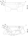
- Figure 1C exemplarily illustrates a cutaway isometric view of the cover assembly 101 about the A-A' axis.
- Figure 1D exemplarily illustrates a sectional view of the cover assembly 101 about the A-A' axis.
- the shell-and-tube heat exchanger assembly 100 may include a first tube sheet 102, a second tube sheet 104, and a plenum 105.
- the first tube sheet 102 is of a solid cuboidal geometrical configuration.
- the plenum 105 and the second tube sheet 104 may be of a solid cylindrical geometrical configuration.
- the first tube sheet 102 is adapted to be secured to the shell 103 of the shell-and-tube heat exchanger assembly 100.
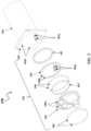
- Figure 2 illustrates an exploded view of the shell-and-tube heat exchanger assembly 100.
- the first tube sheet 102 includes a plurality of first holes 102a adapted to support a plurality of tubes extending through the shell 103.
- the second tube sheet 104 is adapted to be fastened to a front surface of the first tube sheet 102 and fastened to a rear surface of the plenum 105.
- the second tube sheet 104 includes a plurality of second holes 104a adapted to support the plurality of tubes extending through the plurality of first holes 102a.
- the plurality of first holes 102a of the first tube sheet 102 is aligned with the plurality of second holes 104a of the second tube sheet 104.
- the second tube sheet 104 is made of a metal adapted to limit a corrosion response of the plurality of tubes when exposed to the chiller fluid. As such, an electrochemical potential of the metal of the second tube sheet 104 is equivalent or lower than an electrochemical potential of the material of the plurality of tubes.
- the second tube sheet 104 is made of either an aluminum alloy or an inert material or both. The inert material may also include plastics.
- Each of the plurality of tubes may be made of an aluminum alloy. It may be appreciated that the metal of the second tube sheet 104 and the metal of the plurality of tubes may be dissimilar or different.
- the only condition for choosing the metals is that the electrochemical potential of the metal of the second tube sheet 104 is equivalent or lower than an electrochemical potential of the material of the plurality of tubes.
- a sealing element may be disposed in each of the plurality of first holes 102a between the plurality of tubes extending through the shell 103 and the first tube sheet 102.
- a plurality of first openings 102b is defined in the first tube sheet 102
- a plurality of second openings 104b is defined in the second tube sheet 104
- a plurality of third openings 105a is defined in the plenum 105.
- the plurality of second openings 104b and the plurality of third openings 105a are defined near an outer periphery of the second tube sheet 104 and the plenum 105, respectively.
- the first tube sheet 102 is of a solid cuboidal geometrical configuration
- the plurality of first openings 102b are defined in the first tube sheet 102 such that during assembly, the plurality of first openings 102b, the plurality of second openings 104b, and the plurality of third openings 105a align.
- each of the plurality of first openings 102b defined in the first tube sheet 102 are aligned with a corresponding second opening from the plurality of second openings 104b defined in the second tube sheet 104 and a corresponding third opening from the plurality of third opening s 105a defined in the plenum 105.
- a plurality of fasteners 106, 106' may be inserted into the aligned plurality of first openings 102b, the plurality of second openings 104b, and the plurality of third openings 105a.
- the inserted plurality of fasteners 106, 106' ensures the second tube sheet 104 is fastened to a front surface of the first tube sheet 102.
- the inserted plurality of fasteners 106, 106' ensures the second tube sheet 104 is fastened to the rear surface of the plenum 105.
- the plurality of fasteners 106, 106' may include, but are not limited to, at least one of a guiding pin, a screw thread fastener, and a bolt fastener.
- the shell-and-tube heat exchanger assembly 100 may include a plurality of plenums 105 (sometimes called water-boxes).
- the shell-and-tube heat exchanger assembly 100 may also include a first cover assembly 101' including a first plenum 105' and a second cover assembly 101" including a second plenum 105" (not shown) at opposing ends of the shell 103.
- the second plenum 105" may be an upstream plenum and the first plenum 105' may be a downstream plenum, respectively.
- FIG. 1A illustrates only one side of the shell-and-tube heat exchanger assembly 100
- the shell-and-tube heat exchanger assembly 100 includes two sets of cover assemblies 101', 101" (not shown) on opposing ends of the shell 103.
- the two sets of cover assemblies 101', 101" include the two sets of first tube sheets 102, two sets of second tube sheets 104, and the first and second plenums (105', 105").
- Each of the two sets of first tube sheets 102, each of the two sets of second tube sheets 104, and the first and second plenums (105', 105") are disposed on opposing ends of the shell-and-tube heat exchanger assembly 100.
- Figure 3 exemplarily illustrates a flowchart indicating a method 300 for limiting the corrosion response of the plurality of tubes of the shell-and-tube heat exchanger assembly 100.
- Figure 3 exemplarily illustrates a flowchart indicating a method 300 for limiting the corrosion response of the plurality of tubes of the shell-and-tube heat exchanger assembly 100.
- the first tube sheet 102 is secured to the shell 103 of the shell-and-tube heat exchanger assembly 100.
- the first tube sheet 102 has a solid cuboidal geometrical configuration and the shell 103 has a hollow cylindrical geometric configuration.
- the second tube sheet 104 is disposed between the first tube sheet 102 and the plenum 105 of the shell-and-tube heat exchanger assembly 100 such that the second tube sheet 104 is fastened to the front surface of the first tube sheet 102 and the rear surface of the plenum 105.
- the second tube sheet 104 is made of a metal adapted to limit the corrosion response of the plurality of tubes when exposed to the chiller fluid.
- the second tube sheet 104 is made of either an aluminum alloy or an inert material or a combination of both. The inert material may also include plastics.
- the second tube sheet 104 is fastened to the front surface of the first tube sheet 102 and the rear surface of the plenum 105 using at least one of fasteners 106, 106' and industrial adhesives.
- the step of fastening the second tube sheet 104 to the front surface of the first tube sheet 102 and the rear surface of the plenum 105 also includes aligning each of the plurality of first openings 102b defined in the first tube sheet 102 with a corresponding second opening from the plurality of second openings 104b defined in the second tube sheet 104.
- each of the plurality of second openings 104b is aligned with a corresponding third opening from the plurality of third openings 105a defined in the plenum 105.
- the plurality of fasteners 106, 106' are inserted into the aligned plurality of first openings 102b, the plurality of second openings 104b, and the plurality of third openings 105a to fasten the second tube sheet 104 to the front surface of the first tube sheet 102 and fasten the second tube sheet 104 to the rear surface of the plenum 105.
- the replacement of existing copper tubes with aluminum tubes has significant cost savings potential for water cooled chillers.
- the aluminum tubes are rolled in place at the first tube sheets 102 to provide a tight seal. If aluminum tubes are inserted into a first tube sheet 102 made of steel, when exposed to the chiller fluid like water, the aluminum tubes will corrode if no countermeasures are taken.
- the provision of the second tube sheet 104 made of the aluminum alloy limits the corrosion response of the plurality of aluminum tubes when exposed to the chiller fluid such as water.
- the design of the second tube sheet 104 includes the plurality of second holes 104a that match the design of the plurality of first holes 102a defined in the first tube sheet 102.
- This design keeps the structural design of the current shell-and-tube heat exchanger assembly 100 intact with minimal changes. This eliminates the process of lengthy or extensive structural testing to prove the design withstands operational thermomechanical loading, transportation loads, installation, and overall field usage. Since the structure of the shell-and-tube heat exchanger assembly 100 has minimal changes, this solution can be a factory installed option or even a field retrofit with minor modifications.
Landscapes
- Engineering & Computer Science (AREA)
- Physics & Mathematics (AREA)
- Thermal Sciences (AREA)
- Mechanical Engineering (AREA)
- General Engineering & Computer Science (AREA)
- Heat-Exchange Devices With Radiators And Conduit Assemblies (AREA)
Abstract
Description
- This application claims the benefit of
U.S. Provisional Patent Application No. 63/512,369 filed on July 07, 2023 - The invnention generally relates to shell-and-tube heat exchangers. More particularly, the invention relates to a shell-and-tube heat exchanger assembly, and a method for limiting a corrosion response of tubes of the shell-and-tube heat exchanger assembly.
- Shell-and-tube heat exchangers are heat exchangers that include a shell and a bundle of tubes inside the shell. When aluminum tubes are used in a steel shell, the tubes undergo high galvanic corrosion pairing between dissimilar metals and as a result, the material inside the tubes wears off thereby resulting in thinning of the wall. The main drawback of galvanic corrosion is that the pairing can lead to accelerated corrosion and premature failure of metal components or structures. This is because the corrosion rate of the anodic metal can be significantly increased while the cathodic metal is protected. The resulting corrosion products can also cause blockages and reduce the efficiency of fluid flow in heat exchangers, pipes, and other equipment. In some scenarios, the thickness of the wall reduces beyond an allowable limit that can cause the tube to leak or rupture.
- Therefore, there is a need for an improved shell and tube heat exchanger that addresses the drawbacks of galvanic corrosion for specific applications that may use materials with higher galvanic potential than the traditional industry accepted ones.
- This summary is provided to introduce a selection of concepts in a simplified format that are further described in the detailed description. This summary is not intended to identify key or essential inventive concepts of the invention, nor is it intended for determining the scope of the invention, which is defined only by the claims.
- Disclosed herein is a shell-and-tube heat exchanger assembly including a first tube sheet, a second tube sheet, and a plenum. The first tube sheet is adapted to be secured to a shell of the shell-and-tube heat exchanger assembly. The first tube sheet includes a plurality of first holes adapted to support a plurality of tubes extending through the shell. The second tube sheet is adapted to be fastened to a front surface of the first tube sheet and fastened to a rear surface of a plenum. The second tube sheet includes a plurality of second holes adapted to support the plurality of tubes extending through the plurality of first holes such that the second tube sheet is made of a metal adapted to limit a corrosion response of the plurality of tubes when exposed to a chiller fluid.
- Optionally, an electrochemical potential of the metal of the second tube sheet is equivalent or lower than an electrochemical potential of the material of the plurality of tubes.
- Optionally, the second tube sheet is made of at least one of an aluminum alloy and an inert material.
- Optionally, each of the plurality of tubes is made of an aluminum alloy.
- Optionally, the plurality of first holes of the first tube sheet is aligned with the plurality of second holes of the second tube sheet.
- Optionally, a plurality of first openings is defined in the first tube sheet, a plurality of second openings is defined in the second tube sheet, and a plurality of third openings is defined in the plenum.
- Optionally, each of the plurality of first openings defined in the first tube sheet are aligned with a corresponding second opening from the plurality of second openings defined in the second tube sheet and a corresponding third opening from the plurality of third openings defined in the plenum.
- Optionally, a plurality of fasteners are adapted to be inserted into the aligned plurality of first openings, the plurality of second openings, and the plurality of third openings to fasten the second tube sheet to a front surface of the first tube sheet and fasten the second tube sheet to the rear surface of the plenum.
- Optionally, the plurality of fasteners include at least one of a guiding pin, a screw thread fastener, and a bolt fastener.
- Optionally, a sealing element is disposed in each of the plurality of first holes between the plurality of tubes extending through the shell and the first tube sheet.
- Optionally, the chiller fluid inside each of the plurality of tubes is water.
- A method for limiting a corrosion response of a plurality of tubes of a shell-and-tube heat exchanger assembly, is also disclosed. The method includes securing a first tube sheet to a shell of the shell-and-tube heat exchanger assembly. Next, the step includes disposing a second tube sheet between the first tube sheet and a plenum of the shell-and-tube heat exchanger assembly. The second tube sheet is fastened to a front surface of the first tube sheet and a rear surface of the plenum. The second tube sheet is made of a metal adapted to limit a corrosion response of the plurality of tubes when exposed to a chiller fluid.
- Optionally, an electrochemical potential of the metal of the second tube sheet is equivalent or lower than an electrochemical potential of the material of the plurality of tubes.
- Optionally, the second tube sheet is made of at least one of an aluminum alloy and an inert material.
- Optionally, the second tube sheet is fastened to the front surface of the first tube sheet and the rear surface of the plenum using at least one of fasteners and industrial adhesives.
- Optionally, the step of fastening the second tube sheet to the front surface of the first tube sheet and the rear surface of the plenum further includes aligning each of a plurality of first openings defined in the first tube sheet with a corresponding second opening from a plurality of second openings defined in the second tube sheet. Next, each of the plurality of second openings is aligned with a corresponding third opening from a plurality of third openings defined in the plenum. A plurality of fasteners are inserted into the aligned plurality of first openings, the plurality of second openings, and the plurality of third openings to fasten the second tube sheet to the front surface of the first tube sheet and fasten the second tube sheet to the rear surface of the plenum.
- To further clarify the advantages and features of the method and system, a more particular description of the method and system will be rendered by reference to specific embodiments thereof, which is illustrated in the appended drawing. It is appreciated that these drawings depict only exemplary embodiments and are therefore not to be considered limiting on the scope of the invention.
- These and other features, aspects, and advantages of the inventon will become better understood when the following detailed description is read with reference to the accompanying drawings, which are provided by way of example only and in which like characters represent like parts throughout the drawings, wherein:
-
Figure 1A exemplarily illustrates an assembled view of a shell-and-tube heat exchanger assembly; -
Figure 1B exemplarily illustrates an enlarged view of a cover assembly of the shell-and-tube heat exchanger assembly shown inFigure 1A ; -
Figure 1C exemplarily illustrates a cutaway isometric view of the cover assembly about the A-A' axis; -
Figure 1D exemplarily illustrates a sectional view of the cover assembly about the A-A' axis; -
Figure 2 exemplarily illustrates an exploded view of the shell-and-tube heat exchanger assembly; and -
Figure 3 exemplarily illustrates a flowchart indicating a method for limiting a corrosion response of a plurality of tubes of the shell-and-tube heat exchanger assembly. - Further, skilled artisans will appreciate that elements in the drawings are illustrated for simplicity and may not have necessarily been drawn to scale. For example, the flow charts illustrate the method in terms of the most prominent steps involved to help to improve understanding. Furthermore, in terms of the construction of the device, one or more components of the device may have been represented in the drawings by conventional symbols, and the drawings may show only those specific details that are pertinent to understanding so as not to obscure the drawings with details that will be readily apparent to those of ordinary skill in the art having the benefit of the description herein.
- For the purpose of promoting an understanding of the principles of the invention, reference will now be made to the various embodiments and specific language will be used to describe the same. It will nevertheless be understood that no limitation of the scope of the invention is thereby intended.
- It will be understood by those skilled in the art that the foregoing general description and the following detailed description are explanatory of the invention and are not intended to be restrictive thereof.
- Reference throughout this specification to "an aspect", "another aspect" or similar language means that a particular feature, structure, or characteristic described in connection with the embodiment is included in at least one embodiment of the invention. Thus, appearances of the phrase "in an embodiment", "in another embodiment", "some embodiments", "one or more embodiments" and similar language throughout this specification may, but do not necessarily, all refer to the same embodiment.
- The terms "comprises", "comprising", or any other variations thereof, are intended to cover a non-exclusive inclusion, such that a process or method that comprises a list of steps does not include only those steps but may include other steps not expressly listed or inherent to such process or method. Similarly, one or more devices or sub-systems or elements or structures or components proceeded by "comprises... a" does not, without more constraints, preclude the existence of other devices or other sub-systems or other elements or other structures or other components or additional devices or additional sub-systems or additional elements or additional structures or additional components.
- Embodiments will be described below in detail with reference to the accompanying drawings.
- Galvanic corrosion pairing between dissimilar metals is a type of corrosion that occurs when two different metals are in contact with each other in the presence of an electrolyte, such as water or a corrosive fluid. In this situation, the more electronegative metal becomes the anode and corrodes preferentially, while the more electropositive metal becomes the cathode and corrodes less or not at all.
- In the context of heat exchangers, galvanic corrosion pairing between dissimilar metals can be particularly problematic because they often use a combination of different metal alloys, such as copper, brass, stainless steel, aluminum, and titanium. These alloys can have different electrochemical potentials, and if they are in contact with each other, galvanic corrosion can occur. This can lead to leaks, reduced heat transfer efficiency, and costly maintenance or replacement of the heat exchanger.
-
Figure 1A exemplarily illustrates an assembled view of a shell-and-tubeheat exchanger assembly 100. - The shell-and-tube
heat exchanger assembly 100 may include acover assembly 101 and ashell 103 like a large l tank-like vessel and a plurality of tubes bundled inside theshell 103. In an embodiment, the tubes may be made of an aluminum metal or an aluminum alloy. Hereinafter, the tubes may be used to mean aluminum tubes or aluminum alloy tubes. Theshell 103 may have a plurality of ports for supplying fluids within the shell-and-tube heat exchanger. The plurality of ports may include upstream supply ports for supplying fluid within theshell 103 and the tubes separately. For example, the fluid flowing through the tubes may be chiller water and the fluid within theshell 103 may be a refrigerant. Therefore, the upstream supply ports may separately supply chiller water to the tubes and refrigerant to theshell 103. Similarly, one or more exhaust ports may be provided to remove exhaust vapor formed within theshell 103 during a heat transfer cycle of the shell-and-tubeheat exchanger assembly 100. - The shell-and-tube
heat exchanger assembly 100 may be designed to allow one or more fluids such as a first fluid and a second fluid of different starting temperatures to flow therethrough. In an embodiment, the first fluid may be a chiller fluid, for example, water and the second fluid may be a refrigerant. The first fluid may flow through the tubes (the tube side), while the second fluid may flow in the shell 103 (the shell side) but outside the tubes. Heat is transferred between the fluids through the tubes, either from tube side to shell 103 side or vice versa. The fluids may be either liquids or gases on either theshell 103 or the tube side. Several tubes are bundled together within theshell 103 of the shell-and-tubeheat exchanger assembly 100 to increase the heat transfer area. In an embodiment, the tubes are disposed coaxially inside theshell 103 to transfer heat efficiently within the cylindrical tank-like shell 103. -
Figure 1B exemplarily illustrates an enlarged view of thecover assembly 101 of the shell-and-tubeheat exchanger assembly 100 shown inFigure 1A .Figure 1C exemplarily illustrates a cutaway isometric view of thecover assembly 101 about the A-A' axis.Figure 1D exemplarily illustrates a sectional view of thecover assembly 101 about the A-A' axis. The shell-and-tubeheat exchanger assembly 100 may include afirst tube sheet 102, asecond tube sheet 104, and aplenum 105. In an embodiment, thefirst tube sheet 102 is of a solid cuboidal geometrical configuration. Moreover, theplenum 105 and thesecond tube sheet 104 may be of a solid cylindrical geometrical configuration. Thefirst tube sheet 102 is adapted to be secured to theshell 103 of the shell-and-tubeheat exchanger assembly 100. -
Figure 2 illustrates an exploded view of the shell-and-tubeheat exchanger assembly 100. In an embodiment, thefirst tube sheet 102 includes a plurality offirst holes 102a adapted to support a plurality of tubes extending through theshell 103. Thesecond tube sheet 104 is adapted to be fastened to a front surface of thefirst tube sheet 102 and fastened to a rear surface of theplenum 105. Thesecond tube sheet 104 includes a plurality ofsecond holes 104a adapted to support the plurality of tubes extending through the plurality offirst holes 102a. The plurality offirst holes 102a of thefirst tube sheet 102 is aligned with the plurality ofsecond holes 104a of thesecond tube sheet 104. - The
second tube sheet 104 is made of a metal adapted to limit a corrosion response of the plurality of tubes when exposed to the chiller fluid. As such, an electrochemical potential of the metal of thesecond tube sheet 104 is equivalent or lower than an electrochemical potential of the material of the plurality of tubes. In an embodiment, thesecond tube sheet 104 is made of either an aluminum alloy or an inert material or both. The inert material may also include plastics. Each of the plurality of tubes may be made of an aluminum alloy. It may be appreciated that the metal of thesecond tube sheet 104 and the metal of the plurality of tubes may be dissimilar or different. In such a scenario, the only condition for choosing the metals is that the electrochemical potential of the metal of thesecond tube sheet 104 is equivalent or lower than an electrochemical potential of the material of the plurality of tubes. In an embodiment, a sealing element may be disposed in each of the plurality offirst holes 102a between the plurality of tubes extending through theshell 103 and thefirst tube sheet 102. - A plurality of
first openings 102b is defined in thefirst tube sheet 102, a plurality ofsecond openings 104b is defined in thesecond tube sheet 104, and a plurality ofthird openings 105a is defined in theplenum 105. In an embodiment, the plurality ofsecond openings 104b and the plurality ofthird openings 105a are defined near an outer periphery of thesecond tube sheet 104 and theplenum 105, respectively. Although thefirst tube sheet 102 is of a solid cuboidal geometrical configuration, the plurality offirst openings 102b are defined in thefirst tube sheet 102 such that during assembly, the plurality offirst openings 102b, the plurality ofsecond openings 104b, and the plurality ofthird openings 105a align. This means each of the plurality offirst openings 102b defined in thefirst tube sheet 102 are aligned with a corresponding second opening from the plurality ofsecond openings 104b defined in thesecond tube sheet 104 and a corresponding third opening from the plurality of third opening s 105a defined in theplenum 105. - A plurality of
fasteners 106, 106' may be inserted into the aligned plurality offirst openings 102b, the plurality ofsecond openings 104b, and the plurality ofthird openings 105a. The inserted plurality offasteners 106, 106' ensures thesecond tube sheet 104 is fastened to a front surface of thefirst tube sheet 102. Similarly, the inserted plurality offasteners 106, 106' ensures thesecond tube sheet 104 is fastened to the rear surface of theplenum 105. In an embodiment, the plurality offasteners 106, 106' may include, but are not limited to, at least one of a guiding pin, a screw thread fastener, and a bolt fastener. - The shell-and-tube
heat exchanger assembly 100 may include a plurality of plenums 105 (sometimes called water-boxes). The shell-and-tubeheat exchanger assembly 100 may also include a first cover assembly 101' including a first plenum 105' and asecond cover assembly 101" including asecond plenum 105" (not shown) at opposing ends of theshell 103. Thesecond plenum 105" may be an upstream plenum and the first plenum 105' may be a downstream plenum, respectively. AlthoughFigure 1A illustrates only one side of the shell-and-tubeheat exchanger assembly 100, it must be appreciated that the shell-and-tubeheat exchanger assembly 100 includes two sets ofcover assemblies 101', 101" (not shown) on opposing ends of theshell 103. The two sets ofcover assemblies 101', 101" include the two sets offirst tube sheets 102, two sets ofsecond tube sheets 104, and the first and second plenums (105', 105"). Each of the two sets offirst tube sheets 102, each of the two sets ofsecond tube sheets 104, and the first and second plenums (105', 105") are disposed on opposing ends of the shell-and-tubeheat exchanger assembly 100. -
Figure 3 exemplarily illustrates a flowchart indicating amethod 300 for limiting the corrosion response of the plurality of tubes of the shell-and-tubeheat exchanger assembly 100. For the sake of brevity, details that are explained in the description ofFigures 1A-2 are not explained in the description ofFigure 3 . - At
Step 301, thefirst tube sheet 102 is secured to theshell 103 of the shell-and-tubeheat exchanger assembly 100. In an embodiment, thefirst tube sheet 102 has a solid cuboidal geometrical configuration and theshell 103 has a hollow cylindrical geometric configuration. - At
Step 302, thesecond tube sheet 104 is disposed between thefirst tube sheet 102 and theplenum 105 of the shell-and-tubeheat exchanger assembly 100 such that thesecond tube sheet 104 is fastened to the front surface of thefirst tube sheet 102 and the rear surface of theplenum 105. Moreover, thesecond tube sheet 104 is made of a metal adapted to limit the corrosion response of the plurality of tubes when exposed to the chiller fluid. In an embodiment, thesecond tube sheet 104 is made of either an aluminum alloy or an inert material or a combination of both. The inert material may also include plastics. In an embodiment, thesecond tube sheet 104 is fastened to the front surface of thefirst tube sheet 102 and the rear surface of theplenum 105 using at least one offasteners 106, 106' and industrial adhesives. - During assembly, the step of fastening the
second tube sheet 104 to the front surface of thefirst tube sheet 102 and the rear surface of theplenum 105 also includes aligning each of the plurality offirst openings 102b defined in thefirst tube sheet 102 with a corresponding second opening from the plurality ofsecond openings 104b defined in thesecond tube sheet 104. Next, each of the plurality ofsecond openings 104b is aligned with a corresponding third opening from the plurality ofthird openings 105a defined in theplenum 105. Finally, the plurality offasteners 106, 106' are inserted into the aligned plurality offirst openings 102b, the plurality ofsecond openings 104b, and the plurality ofthird openings 105a to fasten thesecond tube sheet 104 to the front surface of thefirst tube sheet 102 and fasten thesecond tube sheet 104 to the rear surface of theplenum 105. - The replacement of existing copper tubes with aluminum tubes has significant cost savings potential for water cooled chillers. The aluminum tubes are rolled in place at the
first tube sheets 102 to provide a tight seal. If aluminum tubes are inserted into afirst tube sheet 102 made of steel, when exposed to the chiller fluid like water, the aluminum tubes will corrode if no countermeasures are taken. Advantageously, the provision of thesecond tube sheet 104 made of the aluminum alloy limits the corrosion response of the plurality of aluminum tubes when exposed to the chiller fluid such as water. - Moreover, the design of the
second tube sheet 104 includes the plurality ofsecond holes 104a that match the design of the plurality offirst holes 102a defined in thefirst tube sheet 102. This design keeps the structural design of the current shell-and-tubeheat exchanger assembly 100 intact with minimal changes. This eliminates the process of lengthy or extensive structural testing to prove the design withstands operational thermomechanical loading, transportation loads, installation, and overall field usage. Since the structure of the shell-and-tubeheat exchanger assembly 100 has minimal changes, this solution can be a factory installed option or even a field retrofit with minor modifications. - As would be apparent to a person in the art, various working modifications may be made to the method in order to implement the inventive concept as taught herein.
- Moreover, the actions of any flow diagram need not be implemented in the order shown; nor do all the acts necessarily need to be performed. Also, those acts that are not dependent on other acts may be performed in parallel with the other acts.
- The drawings and the forgoing description give examples of embodiments. Those skilled in the art will appreciate that one or more of the described elements may well be combined into a single functional element. Alternatively, certain elements may be split into multiple functional elements. Elements from one embodiment may be added to another embodiment. For example, orders of processes described herein may be changed and are not limited to the manner described herein.
- Benefits, other advantages, and solutions to problems have been described above regarding specific embodiments. However, the benefits, advantages, solutions to problems, and any component(s) that may cause any benefit, advantage, or solution to occur or become more pronounced are not to be construed as a critical, or essential feature or component of any or all the claims.
Claims (15)
- A shell-and-tube heat exchanger assembly (100), comprising:a first tube sheet (102) adapted to be secured to a shell (103) of the shell-and-tube heat exchanger assembly, the first tube sheet comprising:
a plurality of first holes (102a) adapted to support a plurality of tubes extending through the shell; anda second tube sheet (104) adapted to be fastened to a front surface of the first tube sheet and fastened to a rear surface of a plenum (105), the second tube sheet comprising:
a plurality of second holes (104a) adapted to support the plurality of tubes extending through the plurality of first holes,wherein the second tube sheet is made of a metal adapted to limit a corrosion response of the plurality of tubes when exposed to a chiller fluid. - The shell-and-tube heat exchanger assembly of claim 1, wherein an electrochemical potential of the metal of the second tube sheet is equivalent or lower than an electrochemical potential of the material of the plurality of tubes.
- The shell-and-tube heat exchanger assembly of claim 1 or 2, wherein the second tube sheet is made of at least one of an aluminum alloy and an inert material.
- The shell-and-tube heat exchanger assembly of any preceding claim, wherein each of the plurality of tubes is made of an aluminum alloy.
- The shell-and-tube heat exchanger assembly of any preceding claim, wherein the plurality of first holes of the first tube sheet is aligned with the plurality of second holes of the second tube sheet.
- The shell-and-tube heat exchanger assembly of any preceding claim, wherein a plurality of first openings (102b) is defined in the first tube sheet, a plurality of second openings (104b) is defined in the second tube sheet, and a plurality of third openings (105a) is defined in the plenum.
- The shell-and-tube heat exchanger assembly of claim 6, wherein each of the plurality of first openings defined in the first tube sheet are aligned with a corresponding second opening from the plurality of second openings defined in the second tube sheet and a corresponding third opening from the plurality of third openings defined in the plenum.
- The shell-and-tube heat exchanger assembly of any preceding claim, wherein a plurality of fasteners (106, 106') are adapted to be inserted into aligned pluralities of first openings (102b), second openings (104b), and third openings (105a) to fasten the second tube sheet to a front surface of the first tube sheet and fasten the second tube sheet to the rear surface of the plenum.
- The shell-and-tube heat exchanger assembly of claim 8, wherein the plurality of fasteners comprise at least one of a guiding pin, a screw thread fastener, and a bolt fastener.
- The shell-and-tube heat exchanger assembly of any preceding claim, wherein a sealing element is disposed in each of the plurality of first holes between the plurality of tubes extending through the shell and the first tube sheet.
- The shell-and-tube heat exchanger assembly of any preceding claim , wherein the chiller fluid inside each of the plurality of tubes is water.
- A method for limiting a corrosion response of a plurality of tubes of a shell-and-tube heat exchanger assembly (100), the method comprising:securing a first tube sheet (102) to a shell (103) of the shell-and-tube heat exchanger assembly;disposing a second tube sheet (104) between the first tube sheet and a plenum (105) of the shell-and-tube heat exchanger assembly,wherein the second tube sheet is fastened to a front surface of the first tube sheet and a rear surface of the plenum,wherein the second tube sheet is made of a metal adapted to limit a corrosion response of the plurality of tubes when exposed to a chiller fluid.
- The method of claim 12, wherein an electrochemical potential of the metal of the second tube sheet is equivalent or lower than an electrochemical potential of the material of the plurality of tubes, and/or wherein the second tube sheet is made of at least one of an aluminum alloy and an inert material.
- The method of claim 12 or 13, wherein the second tube sheet is fastened to the front surface of the first tube sheet and the rear surface of the plenum using at least one of fasteners (106, 106') and industrial adhesives.
- The method of claim 12, 13 or 14, wherein the step of fastening the second tube sheet to the front surface of the first tube sheet and the rear surface of the plenum further comprises:aligning each of a plurality of first openings (102b) defined in the first tube sheet with a corresponding second opening from a plurality of second openings (104b) defined in the second tube sheet;aligning each of the plurality of second openings with a corresponding third opening from a plurality of third openings (105a) defined in the plenum; andinserting a plurality of fasteners (106, 106') into the aligned pluralities of first openings, second openings, and third openings to fasten the second tube sheet to the front surface of the first tube sheet and fasten the second tube sheet to the rear surface of the plenum.
Applications Claiming Priority (1)
| Application Number | Priority Date | Filing Date | Title |
|---|---|---|---|
| US202363512369P | 2023-07-07 | 2023-07-07 |
Publications (1)
| Publication Number | Publication Date |
|---|---|
| EP4488611A1 true EP4488611A1 (en) | 2025-01-08 |
Family
ID=91810220
Family Applications (1)
| Application Number | Title | Priority Date | Filing Date |
|---|---|---|---|
| EP24186309.1A Pending EP4488611A1 (en) | 2023-07-07 | 2024-07-03 | Shell-and-tube heat exchanger assembly and method for limiting a corrosion response of tubes therein |
Country Status (3)
| Country | Link |
|---|---|
| US (1) | US20250012525A1 (en) |
| EP (1) | EP4488611A1 (en) |
| CN (1) | CN119268410A (en) |
Citations (7)
| Publication number | Priority date | Publication date | Assignee | Title |
|---|---|---|---|---|
| US3182720A (en) * | 1961-12-27 | 1965-05-11 | Westinghouse Electric Corp | Heat exchange apparatus |
| US20040261974A1 (en) * | 2003-06-24 | 2004-12-30 | Francesco Pigatto | Tube bundle heat exchanger |
| DE102005059422A1 (en) * | 2005-12-13 | 2007-06-14 | Helmut Aaslepp | Pipe-bundle heat exchanger for seawater application, has soft material profile seals pressed on flange and silicon carbide pipes using screw connection, where connection has threaded bolt and special cap nut for producing tightness |
| US7763215B2 (en) * | 2004-10-01 | 2010-07-27 | Toyo Engineering Corporation | Reactor having detachably fixed tubesheet plate member |
| DE202004021912U1 (en) * | 2004-03-31 | 2012-11-23 | Sgl Carbon Se | Shell and tube heat exchangers |
| US9127896B1 (en) * | 2014-10-14 | 2015-09-08 | Neptune-Benson, Llc | Multi-segmented tube sheet |
| CN110207514A (en) * | 2019-06-28 | 2019-09-06 | 东方电气集团东方电机有限公司 | A kind of sheet assemble bimetallic tube shell-and-tube heat exchanger |
Family Cites Families (2)
| Publication number | Priority date | Publication date | Assignee | Title |
|---|---|---|---|---|
| US20090101321A1 (en) * | 2006-05-03 | 2009-04-23 | Tat Technologies Ltd. | Heat Exchanger |
| WO2021011184A1 (en) * | 2019-07-12 | 2021-01-21 | Carrier Corporation | Shell and tube heat exchanger with compound tubesheet |
-
2024
- 2024-06-25 US US18/753,196 patent/US20250012525A1/en active Pending
- 2024-07-02 CN CN202410878206.8A patent/CN119268410A/en active Pending
- 2024-07-03 EP EP24186309.1A patent/EP4488611A1/en active Pending
Patent Citations (7)
| Publication number | Priority date | Publication date | Assignee | Title |
|---|---|---|---|---|
| US3182720A (en) * | 1961-12-27 | 1965-05-11 | Westinghouse Electric Corp | Heat exchange apparatus |
| US20040261974A1 (en) * | 2003-06-24 | 2004-12-30 | Francesco Pigatto | Tube bundle heat exchanger |
| DE202004021912U1 (en) * | 2004-03-31 | 2012-11-23 | Sgl Carbon Se | Shell and tube heat exchangers |
| US7763215B2 (en) * | 2004-10-01 | 2010-07-27 | Toyo Engineering Corporation | Reactor having detachably fixed tubesheet plate member |
| DE102005059422A1 (en) * | 2005-12-13 | 2007-06-14 | Helmut Aaslepp | Pipe-bundle heat exchanger for seawater application, has soft material profile seals pressed on flange and silicon carbide pipes using screw connection, where connection has threaded bolt and special cap nut for producing tightness |
| US9127896B1 (en) * | 2014-10-14 | 2015-09-08 | Neptune-Benson, Llc | Multi-segmented tube sheet |
| CN110207514A (en) * | 2019-06-28 | 2019-09-06 | 东方电气集团东方电机有限公司 | A kind of sheet assemble bimetallic tube shell-and-tube heat exchanger |
Also Published As
| Publication number | Publication date |
|---|---|
| US20250012525A1 (en) | 2025-01-09 |
| CN119268410A (en) | 2025-01-07 |
Similar Documents
| Publication | Publication Date | Title |
|---|---|---|
| US9534850B2 (en) | Tube bundle heat exchanger | |
| US6206086B1 (en) | Multi-pass tube side heat exchanger with removable bundle | |
| US11215400B2 (en) | Heat exchanger | |
| US10995410B2 (en) | Visual electrolytic corrosion indication and prevention apparatus | |
| WO2005001368A3 (en) | Anti-corrosion protection for heat exchange tube sheet | |
| US20140218148A1 (en) | Rupture resistant system | |
| US20250012525A1 (en) | Shell-and-tube heat exchanger assembly and method forlimiting a corrosion response of tubes therein | |
| US20250012522A1 (en) | Fixing structure and insertion-plate-type heat exchanger having same | |
| CN104428495B (en) | Reaction plate and turbine including reaction plate | |
| CN217442334U (en) | Heat exchanger with flow path short circuit reduction guide cylinder structure | |
| CN210346425U (en) | Sealing structure between heat exchanger baffle plate and barrel | |
| JP2013224758A (en) | Water-cooled heat exchanger | |
| JP2009534624A (en) | Sealing structure of inner tube sheet of tubular heat exchanger | |
| EP3204713B1 (en) | True countercurrent tema type bfu special | |
| CN219051278U (en) | Micro-reaction device | |
| EP3997406B1 (en) | Shell and tube heat exchanger with compound tubesheet | |
| CN219736066U (en) | Integrated two-stage anti-corrosion heat exchanger | |
| JP2010127506A (en) | Heat exchange device | |
| SE518971C2 (en) | Feeding device for a plate heat exchanger, plate heat exchanger and method for manufacturing such a | |
| CN117870442B (en) | Sealing device of shell side partition plate and heat exchanger | |
| CN210718804U (en) | Heat exchange tube supporting structure | |
| CN220039226U (en) | Corrosion-resistant tube plate and corrosion-resistant heat exchanger | |
| CN222378904U (en) | Heat exchange tube and heat exchanger | |
| EP4365531A1 (en) | Header arrangement, method of assembling a header arrangement and heat exchanger | |
| CN221800924U (en) | High-temperature-resistant assembled spiral air duct |
Legal Events
| Date | Code | Title | Description |
|---|---|---|---|
| PUAI | Public reference made under article 153(3) epc to a published international application that has entered the european phase |
Free format text: ORIGINAL CODE: 0009012 |
|
| STAA | Information on the status of an ep patent application or granted ep patent |
Free format text: STATUS: THE APPLICATION HAS BEEN PUBLISHED |
|
| AK | Designated contracting states |
Kind code of ref document: A1 Designated state(s): AL AT BE BG CH CY CZ DE DK EE ES FI FR GB GR HR HU IE IS IT LI LT LU LV MC ME MK MT NL NO PL PT RO RS SE SI SK SM TR |
|
| STAA | Information on the status of an ep patent application or granted ep patent |
Free format text: STATUS: REQUEST FOR EXAMINATION WAS MADE |
|
| 17P | Request for examination filed |
Effective date: 20250410 |
|
| GRAP | Despatch of communication of intention to grant a patent |
Free format text: ORIGINAL CODE: EPIDOSNIGR1 |
|
| STAA | Information on the status of an ep patent application or granted ep patent |
Free format text: STATUS: GRANT OF PATENT IS INTENDED |
|
| RIC1 | Information provided on ipc code assigned before grant |
Ipc: F28F 9/02 20060101AFI20260331BHEP Ipc: F28F 21/08 20060101ALI20260331BHEP Ipc: F28F 19/00 20060101ALN20260331BHEP Ipc: F28D 7/16 20060101ALN20260331BHEP Ipc: F28D 7/06 20060101ALN20260331BHEP |