EP4488595A1 - Ultraviolet radiation unit and air-conditioning device - Google Patents
Ultraviolet radiation unit and air-conditioning device Download PDFInfo
- Publication number
- EP4488595A1 EP4488595A1 EP23763186.6A EP23763186A EP4488595A1 EP 4488595 A1 EP4488595 A1 EP 4488595A1 EP 23763186 A EP23763186 A EP 23763186A EP 4488595 A1 EP4488595 A1 EP 4488595A1
- Authority
- EP
- European Patent Office
- Prior art keywords
- light source
- control unit
- unit
- air conditioner
- indoor
- Prior art date
- Legal status (The legal status is an assumption and is not a legal conclusion. Google has not performed a legal analysis and makes no representation as to the accuracy of the status listed.)
- Pending
Links
Images




Classifications
-
- F—MECHANICAL ENGINEERING; LIGHTING; HEATING; WEAPONS; BLASTING
- F24—HEATING; RANGES; VENTILATING
- F24F—AIR-CONDITIONING; AIR-HUMIDIFICATION; VENTILATION; USE OF AIR CURRENTS FOR SCREENING
- F24F1/00—Room units for air-conditioning, e.g. separate or self-contained units or units receiving primary air from a central station
- F24F1/0007—Indoor units, e.g. fan coil units
- F24F1/0071—Indoor units, e.g. fan coil units with means for purifying supplied air
-
- F—MECHANICAL ENGINEERING; LIGHTING; HEATING; WEAPONS; BLASTING
- F24—HEATING; RANGES; VENTILATING
- F24F—AIR-CONDITIONING; AIR-HUMIDIFICATION; VENTILATION; USE OF AIR CURRENTS FOR SCREENING
- F24F1/00—Room units for air-conditioning, e.g. separate or self-contained units or units receiving primary air from a central station
- F24F1/0007—Indoor units, e.g. fan coil units
- F24F1/0071—Indoor units, e.g. fan coil units with means for purifying supplied air
- F24F1/0076—Indoor units, e.g. fan coil units with means for purifying supplied air by electric means, e.g. ionisers or electrostatic separators
-
- F—MECHANICAL ENGINEERING; LIGHTING; HEATING; WEAPONS; BLASTING
- F24—HEATING; RANGES; VENTILATING
- F24F—AIR-CONDITIONING; AIR-HUMIDIFICATION; VENTILATION; USE OF AIR CURRENTS FOR SCREENING
- F24F11/00—Control or safety arrangements
- F24F11/70—Control systems characterised by their outputs; Constructional details thereof
-
- F—MECHANICAL ENGINEERING; LIGHTING; HEATING; WEAPONS; BLASTING
- F24—HEATING; RANGES; VENTILATING
- F24F—AIR-CONDITIONING; AIR-HUMIDIFICATION; VENTILATION; USE OF AIR CURRENTS FOR SCREENING
- F24F11/00—Control or safety arrangements
- F24F11/70—Control systems characterised by their outputs; Constructional details thereof
- F24F11/72—Control systems characterised by their outputs; Constructional details thereof for controlling the supply of treated air, e.g. its pressure
-
- F—MECHANICAL ENGINEERING; LIGHTING; HEATING; WEAPONS; BLASTING
- F24—HEATING; RANGES; VENTILATING
- F24F—AIR-CONDITIONING; AIR-HUMIDIFICATION; VENTILATION; USE OF AIR CURRENTS FOR SCREENING
- F24F8/00—Treatment, e.g. purification, of air supplied to human living or working spaces otherwise than by heating, cooling, humidifying or drying
- F24F8/20—Treatment, e.g. purification, of air supplied to human living or working spaces otherwise than by heating, cooling, humidifying or drying by sterilisation
- F24F8/22—Treatment, e.g. purification, of air supplied to human living or working spaces otherwise than by heating, cooling, humidifying or drying by sterilisation using UV light
Definitions
- the present disclosure relates to an ultraviolet irradiation unit and an air conditioner.
- an air conditioner including an ultraviolet irradiation unit (irradiator) that irradiates an ultraviolet ray is known (see, for example, PATENT LITERATURE 1).
- the air conditioner includes an air conditioning control unit that controls various operations of the air conditioner, and the air conditioning control unit controls the operation of the ultraviolet irradiation unit.
- the ultraviolet irradiation unit is an optional item in some cases. That is, the air conditioner is used in a configuration not including the ultraviolet irradiation unit in some cases. However, in the air conditioner, it is necessary to store a control program for controlling the ultraviolet irradiation unit in advance in the air conditioning control unit whether or not the ultraviolet irradiation unit is provided.
- the light source control unit having a simple configuration can suppress deterioration of the light source due to an influence of an ambient temperature.
- FIG. 1 is a schematic configuration diagram of the air conditioner including the ultraviolet irradiation unit of the present disclosure.
- An air conditioner 10 illustrated in FIG. 1 is an embodiment of the air conditioner of the present disclosure, can cool and heat a target space constructed inside a building by performing a vapor compression refrigeration cycle, and adjusts a temperature of air in the target space to a predetermined target temperature.
- the air conditioner 10 includes an indoor unit 20 and an outdoor unit 30.
- the air conditioner 10 has a configuration in which one indoor unit 20 is connected to one outdoor unit 30.
- the number of the indoor units 20 and the number of the outdoor units 30 are not limited to one.
- the present embodiment exemplifies the air conditioner 10 configured to circulate a refrigerant in a refrigerant circuit to execute a cooling operation and a heating operation.
- the air conditioner of the present disclosure should not be limited to such a case, and may alternatively be configured to circulate cold water and warm water supplied from a heat source device to execute the cooling operation and the heating operation, and the indoor unit may be a so-called fan coil unit.
- the casing 21 includes a suction port 25 and an air supply port 26.
- the indoor fan 22 is configured to take indoor air (return air RA) into the casing 21 from the suction port 25, cause the taken air to exchange heat with the refrigerant in the indoor heat exchanger 23, and then blow the air (supply air SA) into a room through the air supply port 26.
- the indoor fan 22 includes, for example, a motor (not shown) whose number of operating rotations can be adjusted by inverter control.
- the indoor heat exchanger 23 constitutes a part of a refrigerant circuit 40 to be described later.
- the indoor heat exchanger 23 is of a cross-fin tube type or a microchannel type, and is used for heat exchange with the indoor air.
- the indoor unit 20 includes the collecting member 24 inside the casing 21.
- the collecting member 24 is a member for collecting dust included in the air (return air RA) in an indoor space, and is disposed near the suction port 25 inside the casing 21. In the air conditioner 10, the entire amount of air taken into the casing 21 from the suction port 25 passes through the collecting member 24.
- the outdoor unit 30 includes a casing 31, an outdoor fan 32, an outdoor heat exchanger 33, a compressor 34, a four-way switching valve 35, an electric expansion valve 36, a liquid shutoff valve 37, and a gas shutoff valve 38.
- the compressor 34, the four-way switching valve 35, the outdoor heat exchanger 33, the electric expansion valve 36, the liquid shutoff valve 37, and the gas shutoff valve 38 constitute a part of the refrigerant circuit 40 to be described later.
- the outdoor heat exchanger 33 is, for example, a cross-fin tube type or microchannel type heat exchanger, and is used to exchange heat with the refrigerant by using air as a heat source.
- the four-way switching valve 35 reverses a flow of refrigerant in the refrigerant pipe and switches and supplies the refrigerant discharged from the compressor 34 to either the outdoor heat exchanger 33 or the indoor heat exchanger 23.
- the electric expansion valve 36 includes a motor valve that can adjust a refrigerant flow rate or the like.
- the four-way switching valve 35 is held in a state indicated by solid lines in FIG. 1 .
- a high-temperature and high-pressure gaseous refrigerant discharged from the compressor 34 flows into the outdoor heat exchanger 33 through the four-way switching valve 35, and exchanges heat with outdoor air by activation of the outdoor fan 32 to be condensed and liquefied.
- the outdoor heat exchanger 33 functions as a condenser.
- the liquefied refrigerant passes through the electric expansion valve 36 in a fully open state and flows into the indoor unit 20. In the indoor unit 20, the refrigerant is evaporated by heat exchange with the indoor air in the indoor heat exchanger 23.
- the indoor air cooled by the evaporation of the refrigerant is blown into the room by the indoor fan 22 to cool the room.
- the refrigerant evaporated in the indoor heat exchanger 23 returns to the outdoor unit 30 through the gas refrigerant pipe 40G, and is sucked into the compressor 34 via the four-way switching valve 35.
- the indoor heat exchanger 23 functions as an evaporator.
- the four-way switching valve 35 is maintained in a state indicated by broken lines in FIG. 1 .
- a high-temperature and high-pressure gaseous refrigerant discharged from the compressor 34 passes through the four-way switching valve 35 and flows into the indoor heat exchanger 23 of the indoor unit 20.
- the indoor heat exchanger 23 the refrigerant exchanges heat with the indoor air to be condensed and liquefied.
- the indoor heat exchanger 23 functions as a condenser. The indoor air heated by the condensation of the refrigerant is blown into the room by the indoor fan 22 to heat the room.
- the refrigerant liquefied in the indoor heat exchanger 23 returns to the outdoor unit 30 through the liquid refrigerant pipe 40L, is decompressed to have predetermined low pressure at the electric expansion valve 36, and further exchanges heat with the outdoor air in the outdoor heat exchanger 33 to be evaporated.
- the refrigerant evaporated and gasified in the outdoor heat exchanger 33 passes the four-way switching valve 35 to be sucked into the compressor 34.
- the outdoor heat exchanger 33 functions as an evaporator.
- the air conditioning control unit 15 is a device that controls the operation of the indoor unit 20 and the outdoor unit 30, and includes, for example, a microcomputer including a processor such as a CPU, and memory such as RAM and ROM.
- the air conditioning control unit 15 may be implemented as hardware by using an LSI, an ASIC, an FPGA, or the like.
- the air conditioning control unit 15 exerts a predetermined function when the processor executes a program installed in the memory. Detection values of the sensors provided in the indoor unit 20 and the outdoor unit 30 are input to the air conditioning control unit 15.
- the air conditioning control unit 15 controls the operations of the indoor fan 22, the outdoor fan 32, the compressor 34, the four-way switching valve 35, the electric expansion valve 36, and the like based on the detection values of the sensors and the like.
- the remote controller 16 is an operation unit that allows the user to perform operations such as activation, stop, and change of setting of the air conditioner 10.
- the remote controller 16 is provided with a display 17.
- the display 17 is a part that can display an operation state, a set value, and the like of the air conditioner 10.
- the user can know the operation state of the air conditioner 10 based on the information presented on the display 17.
- FIG. 3 is a perspective view of the indoor unit in the air conditioner of the present disclosure.
- FIG. 4 is a sectional view of the indoor unit with a decorative panel being detached.
- FIG. 5 is a perspective view of the indoor unit with the decorative panel and a protecting member being detached.
- the indoor unit 20 has a so-called cassette type, and includes the casing 21 and a decorative panel 28.
- the casing 21 has a substantially rectangular shape in a bottom view, and includes a first casing 21a disposed in an upper portion and a second casing 21b disposed in a lower portion. As illustrated in FIG. 4 , the casing 21 is provided therein with a space A accommodating the indoor fan 22, the indoor heat exchanger 23, the collecting member 24, the ultraviolet irradiation unit 50, and the like. The space A also serves as an air flow path in the casing 21. As illustrated in FIG. 4 , the casing 21 has a lower end provided with the suction port 25 located at a center of the rectangular shape, and four air supply ports 26 surrounding the suction port 25. The suction port 25 and the air supply ports 26 are openings provided at a lower end of the space A.
- the decorative panel 28 has a substantially rectangular shape in a bottom view, and a suction grill 29 is disposed at a center of the rectangular shape.
- the decorative panel 28 includes four blow-out ports 28a disposed to surround the suction grill 29.
- the suction grill 29 is provided with an opening 29a having a slit shape.
- the opening 29a is in communication with the space A (see FIG. 4 ) via the suction port 25 (see FIG. 4 ).
- the blow-out ports 28a of the decorative panel 28 are in communication with the space A (see FIG. 5 ) via the air supply ports 26 (see FIG. 3 ).
- the indoor unit 20 sucks the indoor air into the casing 21 through the suction port 25 (opening 29a), and supplies the air sucked into the casing 21 into the room through the air supply port 26 and the blow-out port 28a.
- the indoor unit 20 includes the indoor fan 22 and the indoor heat exchanger 23 in the casing 21 (space A).
- the indoor fan 22 is a fan for circulating the indoor air.
- the indoor heat exchanger 23 constitutes a part of the refrigerant circuit 40, and the refrigerant is circulated between the indoor heat exchanger 23 and the outdoor unit 30 through the connection pipe 27.
- the indoor unit 20 drives the indoor fan 22 to cause the indoor air (return air RA) to be sucked into the casing 21 from the suction port 25 (opening 29a) and pass through the indoor heat exchanger 23, and cause cooled or heated air (supply air SA) to be supplied into the room from the air supply port 26 and the blow-out port 28a.
- return air RA return air
- supply air SA cooled or heated air
- the indoor unit 20 includes the ultraviolet irradiation unit 50.
- the ultraviolet irradiation unit 50 is a portion that irradiates the lower end surface 24c of the first filter 24a with the ultraviolet ray UV, and includes the light source 51, the light source control unit 52 (see FIG. 2 ), and a cover 53.
- the light source 51 includes an LED device that generates the ultraviolet ray UV when electrified.
- the light source 51 is equipped with a lens (not shown) that diffuses the ultraviolet ray UV generated by the light source 51 substantially entirely on the lower end surface 24c.
- the light source 51 according to the present embodiment is fixed to the casing 21 and irradiates the lower end surface 24c with the ultraviolet ray UV from a fixed position.
- the light source 51 may further include a displacement mechanism configured to displace the light source 51 with respect to the casing 21, and may be configured to irradiate the lower end surface 24c with the ultraviolet ray UV while being displaced by the displacement mechanism.
- the ultraviolet irradiation unit 50 is disposed at a position deviated from an air flow from the suction port 25 toward the collecting member 24. In other words, the ultraviolet irradiation unit 50 is located not to be overlapped with the suction port 25 and the collecting member 24 in a bottom view. If the ultraviolet irradiation unit 50 is disposed in the air flow from the suction port 25 toward the collecting member 24, the ultraviolet irradiation unit 50 will increase air flow resistance. In the indoor unit 20 of the present disclosure, the ultraviolet irradiation unit 50 is disposed at a position deviated from the air flow from the suction port 25 toward the collecting member 24 in order to inhibit increase in air flow resistance.
- the ultraviolet irradiation unit 50 includes the cover 53.
- the cover 53 also serves as a member supporting the light source 51 on the casing 21, and is screwed to the casing 21.
- the cover 53 includes a body 53a and an opening 53b.
- the ultraviolet ray UV emitted from the light source 51 passes through the opening 53b and is irradiated to the space A outside the cover 53.
- the ultraviolet ray UV emitted to the space A outside the cover 53 through the opening 53b is emitted to the lower end surface 24c of the collecting member 24.
- the air conditioner 10 further includes a notification unit 60.
- the light source control unit 52 transmits the third signal S3 to the air conditioning control unit 15 when detecting an abnormality of the light source 51.
- the air conditioning control unit 15 receives the third signal S3, the air conditioning control unit 15 causes the notification unit 60 to notify.
- the notification unit 60 can notify the user that an abnormality has occurred in the light source 51.
- the light source control unit 52 detects an abnormality of the light source 51, for example, information for notifing the abnormality may be displayed on the display 17 of the remote controller 16.
- FIG. 7 is a control flowchart of the air conditioning control unit.
- the air conditioning control unit 15 starts a control operation illustrated in FIG. 7 .
- the control operation illustrated in FIG. 7 is an operation for controlling the operation of an optional item attachable to the air conditioner 10.
- the optional item attachable to the air conditioner 10 is the ultraviolet irradiation unit 50.
- optional items other than the ultraviolet irradiation unit 50 include an electric dust collector, a deodorizing unit, and a discharging unit that generates active species.
- step (S101) the air conditioning control unit 15 determines whether the ultraviolet irradiation unit 50 is connected to the air conditioner 10 (air conditioning control unit 15).
- step (S102) the air conditioning control unit 15 subsequently executes step (S102).
- step (S101) when determining in step (S101) that the ultraviolet irradiation unit 50 is not connected to the air conditioner 10 (air conditioning control unit 15) (NO), the air conditioning control unit 15 determines that there is no need to execute the control operation for the ultraviolet irradiation unit 50 and ends the control.
- the air conditioning control unit 15 may transmit the first signal S1 when only the conditions (1) and (2) are satisfied. In this case, when the indoor fan 22 is turned off, the air conditioning control unit 15 can still transmit the first signal. In this case, the ultraviolet ray UV can be irradiated by the light source 51 in a state where the indoor fan 22 is turned off.
- the air conditioning control unit 15 transmits the first signal S1 in step (S104), and then executes step (S105).
- step (S105) the air conditioning control unit 15 determines whether the remote controller 16 is turned on. When determining in step (S105) that the remote controller 16 is turned on (YES), the air conditioning control unit 15 subsequently executes step (S106). On the other hand, when determining in step (S105) that the remote controller 16 is not turned on (NO) (that is, when the air conditioner 10 is turned off), the air conditioning control unit 15 subsequently executes step (S109).
- step (S107) the air conditioning control unit 15 determines whether the indoor fan 22 is turned on. When determining in step (S107) that the indoor fan 22 is turned on (YES), the air conditioning control unit 15 repeatedly executes steps (S105) to (S107) until the indoor fan 22 is turned off. On the other hand, when determining in step (S107) that the indoor fan 22 is not turned on (NO) (that is, when the air conditioner 10 is in an automatic stopped state by thermo-on or thermo-off), the air conditioning control unit 15 subsequently ends step (S108).
- the air conditioning control unit 15 transmits the second signal S2 and ends the control operation for the ultraviolet irradiation unit 50 in step (S109).
- the air conditioning control unit 15 transmits only the first signal S1 that permits the operation of the ultraviolet irradiation unit 50 and the second signal S2 that stops the operation for the ultraviolet irradiation unit 50. In other words, the air conditioning control unit 15 does not control the operation of the ultraviolet irradiation unit 50 (specifically, ON and OFF operation of the light source 51).
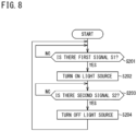
- FIG. 8 is a control flowchart of a light source control unit according to a first embodiment.
- a control operation illustrated in FIG. 8 is a first embodiment of the control operation of controlling the operation of the light source 51 of the ultraviolet irradiation unit 50.
- the light source control unit 52 starts the control operation illustrated in FIG. 8 .
- step (S201) when starting an operation control of the light source 51, the light source control unit 52 executes step (S201).
- step (S201) the light source control unit 52 determines whether the first signal S1 is input.
- step (S201) determines whether the first signal S1 is input.
- the light source control unit 52 subsequently executes step (S202).
- step (S201) determines whether the first signal S1 is input (YES)
- the light source control unit 52 subsequently executes step (S202).
- step (S201) determines whether the first signal S1 is input.
- step (S202) the light source control unit 52 turns on the power source of the light source 51.
- the ultraviolet ray UV is irradiated from the light source 51 toward the lower end surface 24c of the collecting member 24.
- the light source control unit 52 After turning off the power source of the light source 51 in step (S204), the light source control unit 52 returns to step (S201) and executes the control operation in and after step (S201) again.
- the light source control unit 52 turns off the power source of the light source 51 when detecting from the first information J1 that an ambient temperature of the light source 51 exceeds 40 degrees, and the light source control unit 52 turns on the power source of the light source 51 when detecting that the ambient temperature of the light source 51 is less than 40 degrees.
- the air conditioner 10 having such a configuration can suppress a decrease in the life of the light source 51.
- the ultraviolet irradiation unit 50 is not required to be provide with a temperature sensor, and the configuration of the ultraviolet irradiation unit 50 can be simplified.
- step (S200) when starting the operation control of the light source 51, the light source control unit 52 executes step (S200).
- step (S200) the light source control unit 52 determines whether there is an abnormality in the light source 51.
- step (S201) the light source control unit 52 subsequently executes step (S201).
- step (S205) the light source control unit 52 subsequently executes step (S205).
- step (S213) the light source control unit 52 determines whether a first predetermined period X1 has elapsed after the power source of the light source 51 is turned on.
- step (S213) the light source control unit 52 subsequently executes step (S215).
- step (S214) the light source control unit 52 subsequently executes step (S214).
- step (S215) the light source control unit 52 turns off the power source of the light source 51.
- step (S215) the light source control unit 52 subsequently executes step (S216).
- the power source of the light source 51 may be turned off when the first predetermined time X1 has elapsed after the power source of the light source 51 is turned on.
- the light source control unit 52 when starting the control operation of the light source 51, the light source control unit 52 first executes step (S220), resets an integrated irradiation time T of the light source 51 to "0", and then executes step (S221).
- step (S221) the light source control unit 52 determines whether the first signal S1 is input. When determining in step (S211) that the first signal S1 is input (YES), the light source control unit 52 subsequently executes step (S222). On the other hand, when determining in step (S221) that the first signal S1 is not input (NO), the light source control unit 52 repeatedly executes step (S221) until the first signal S1 is input.
- step (S222) the light source control unit 52 determines whether the integrated irradiation time T of the light source 51 is less than a predetermined threshold value Y When determining in step (S222) that the integrated irradiation time T of the light source 51 is less than the predetermined threshold value Y (YES), the light source control unit 52 subsequently executes step (S223). On the other hand, when determining in step (S222) that the integrated irradiation time T of the light source 51 exceeds the predetermined threshold value Y (NO), the light source control unit 52 subsequently executes step (S229).
- step (S223) the light source control unit 52 turns on the power source of the light source 51.
- the ultraviolet ray UV is irradiated from the light source 51 toward the lower end surface 24c of the collecting member 24.
- step (S225) the light source control unit 52 determines whether the integrated irradiation time T of the light source 51 is less than the predetermined threshold value Y.
- step (S225) determines whether the integrated irradiation time T of the light source 51 is less than the predetermined threshold value Y.
- step (S225) determines whether the integrated irradiation time T of the light source 51 is less than the predetermined threshold value Y (YES)
- the light source control unit 52 subsequently executes step (S226).
- step (S225) that the integrated irradiation time T of the light source 51 exceeds the predetermined threshold value Y (NO)
- step (S227) determines whether the integrated irradiation time T of the light source 51 is less than the predetermined threshold value Y.
- step (S227) the light source control unit 52 resets the integrated irradiation time T of the light source 51 to "0", and then executes step (S228).
- step (S226) the light source control unit 52 determines whether the second signal S2 is input. When determining in step (S226) that the second signal S2 is input (YES), the light source control unit 52 subsequently executes step (S228). On the other hand, when determining in step (S226) that the second signal S2 is not input (NO), the light source control unit 52 repeatedly executes steps (S225) and (S226) until the second signal S2 is input.
- step (S228) the light source control unit 52 turns off the power source of the light source 51. After turning off the light source 51 in step (S228), the light source control unit 52 executes step (S230). In steps (S222) to (S229), similarly, the light source control unit 52 resets the integrated irradiation time T of the light source 51 to "0", and then executes step (S230).
- step (S230) the light source control unit 52 determines whether a timing has come at which the irradiation of the ultraviolet ray UV by of the light source 51 is possible.
- step (S230) determines whether a timing has come at which the irradiation of the ultraviolet ray UV by the light source 51 is possible.
- the light source control unit 52 returns to step (S221).
- step (S230) when determining that the timing has not come at which the irradiation of the ultraviolet ray UV by the light source 51 is possible (NO), the light source control unit 52 repeatedly executes step (S230) until the timing comes at which the irradiation of the ultraviolet ray UV by the light source 51 is possible.
- the upper limit of the irradiation time per day is set in consideration of the life of the light source 51.
- the irradiation time of the ultraviolet ray UV by the light source 51 does not reach the upper limit on a certain day corresponds to the timing at which the irradiation of the ultraviolet ray UV by the light source 51 is possible.
- the irradiation time of the ultraviolet ray UV by the light source 51 reaches the upper limit on a certain day corresponds to the timing at which the irradiation of the ultraviolet ray UV by the light source 51 is impossible.
- step (S230) When the irradiation time per day exceeds the upper limit threshold value Y and the light source is turned off after steps (S227) and (S229), the irradiation by the light source cannot be performed on that day, and thus, in step (S230), standby is performed until the next day.
- the light source control unit 52 controls ON and OFF of the power source of the light source 51 in accordance with the integrated irradiation time T of the light source 51.
- the light source control unit 52 having a simple configuration can suppress deterioration of the light source 51 due to the influence of the ambient temperature.
Landscapes
- Engineering & Computer Science (AREA)
- Chemical & Material Sciences (AREA)
- Combustion & Propulsion (AREA)
- Mechanical Engineering (AREA)
- General Engineering & Computer Science (AREA)
- Air Conditioning Control Device (AREA)
- Air Filters, Heat-Exchange Apparatuses, And Housings Of Air-Conditioning Units (AREA)
Abstract
Description
- The present disclosure relates to an ultraviolet irradiation unit and an air conditioner.
- Conventionally, an air conditioner including an ultraviolet irradiation unit (irradiator) that irradiates an ultraviolet ray is known (see, for example, PATENT LITERATURE 1). The air conditioner includes an air conditioning control unit that controls various operations of the air conditioner, and the air conditioning control unit controls the operation of the ultraviolet irradiation unit.
- PATENT LITERATURE 1:
Japanese Laid-Open Patent Publication No. 2021-055892 - In the air conditioner, the ultraviolet irradiation unit is an optional item in some cases. That is, the air conditioner is used in a configuration not including the ultraviolet irradiation unit in some cases. However, in the air conditioner, it is necessary to store a control program for controlling the ultraviolet irradiation unit in advance in the air conditioning control unit whether or not the ultraviolet irradiation unit is provided.
- An object of the present disclosure is to provide an ultraviolet irradiation unit that does not need to store a control program for the ultraviolet irradiation unit in an air conditioning control unit of an air conditioner, and an air conditioner including the ultraviolet irradiation unit.
-
- (1) An ultraviolet irradiation unit of the present disclosure is attachable to an air conditioner including an indoor unit having an indoor fan and an air conditioning control unit that controls an operation of the indoor unit, the ultraviolet irradiation unit including a light source that irradiates the indoor unit with an ultraviolet ray, and a light source control unit that is capable of communicating with the air conditioning control unit and controls an operation of the light source, in which the light source control unit turns on a power source of the light source when receiving a first signal transmitted from the air conditioning control unit.
The ultraviolet irradiation unit of the present disclosure eliminates the need for storing in advance a control program for controlling the ultraviolet irradiation unit in the air conditioning control unit of the air conditioner to which the ultraviolet irradiation unit is attachable. Therefore, the configuration of the air conditioning control unit can be simplified by using the ultraviolet irradiation unit of the present disclosure. - (2) In the ultraviolet irradiation unit of the present disclosure, the light source control unit preferably turns off the power source of the light source when a predetermined period has elapsed after reception of the first signal.
In this case, the light source control unit can easily turn on and off the light source. The configuration of the light source control unit of the ultraviolet irradiation unit can be simplified. - (3) In the ultraviolet irradiation unit of the present disclosure, the light source control unit preferably turns off the power source of the light source upon reception of a second signal transmitted from the air conditioning control unit when the air conditioner stops operating or when the indoor fan stops operating.
In this case, the light source control unit can easily turn on and off the light source in accordance with an operation state of the air conditioner. - (4) An air conditioner of the present disclosure includes an indoor unit including a casing having a suction port through which indoor air is sucked, an indoor fan accommodated in the casing, and a collecting member accommodated in the casing, an air conditioning control unit that controls an operation of the indoor unit, and an ultraviolet irradiation unit including a light source that irradiates the collecting member with an ultraviolet ray and a light source control unit that is capable of communicating with the air conditioning control unit and controls an operation of the light source, in which the light source control unit turns on a power source of the light source when receiving a first signal transmitted from the air conditioning control unit.
The air conditioner of the present disclosure eliminates the need for storing in advance a control program for controlling the ultraviolet irradiation unit in the air conditioning control unit. Therefore, the configuration of the air conditioning control unit can be simplified in the air conditioner of the present disclosure. - (5) In the air conditioner of the present disclosure, when the air conditioner starts operating or when the indoor fan starts operating, the air conditioning control unit preferably transmits the first signal.
In this case, the configuration of the air conditioning control unit can be simplified. - (6) In the air conditioner of the present disclosure, the light source control unit preferably turns off the power source of the light source after a predetermined period elapses following reception of the first signal.
In this case, the light source control unit can easily turn on and off the light source in accordance with the operation state of the air conditioner. - (7) In the air conditioner of the present disclosure, the air conditioning control unit preferably transmits a second signal when the air conditioner stops operating or when the indoor fan stops operating, and the light source control unit preferably turns off the power source of the light source when receiving the second signal.
In this case, the configuration of the light source control unit can be simplified. - (8) The air conditioner of the present disclosure further includes a notification unit, in which the light source control unit preferably transmits a third signal to the air conditioning control unit when detecting an abnormality of the light source, and the air conditioning control unit preferably causes the notification unit to notify when receiving the third signal.
In this case, the notification unit can notify a user that an abnormality has occurred in the light source. - (9) In the air conditioner of the present disclosure, the light source control unit receives first information related to an indoor temperature from the air conditioning control unit, and the light source control unit turns on and off the power source of the light source based on the first information.
- In this case, the light source control unit having a simple configuration can suppress deterioration of the light source due to an influence of an ambient temperature.
-
-
FIG. 1 is a schematic configuration diagram of an air conditioner including an ultraviolet irradiation unit of the present disclosure. -
FIG. 2 is a control block diagram of the air conditioner of the present disclosure. -
FIG. 3 is a perspective view of an indoor unit in the air conditioner of the present disclosure. -
FIG. 4 is a sectional view of the indoor unit with a decorative panel being detached. -
FIG. 5 is a perspective view of the indoor unit with the decorative panel and a protecting member being detached. -
FIG. 6 is a partially enlarged perspective view of the ultraviolet irradiation unit attached to the air conditioner. -
FIG. 7 is a control flowchart of an air conditioning control unit. -
FIG. 8 is a control flowchart of a light source control unit according to a first embodiment. -
FIG. 9 is a control flowchart of a light source control unit according to a second embodiment. -
FIG. 10 is a control flowchart of a light source control unit according to a third embodiment. -
FIG. 11 is a control flowchart of a light source control unit according to a fourth embodiment. - Hereinafter, embodiments of an ultraviolet irradiation unit and an air conditioner including the ultraviolet irradiation unit of the present disclosure will be described in detail with reference to the accompanying drawings.
-
FIG. 1 is a schematic configuration diagram of the air conditioner including the ultraviolet irradiation unit of the present disclosure. Anair conditioner 10 illustrated inFIG. 1 is an embodiment of the air conditioner of the present disclosure, can cool and heat a target space constructed inside a building by performing a vapor compression refrigeration cycle, and adjusts a temperature of air in the target space to a predetermined target temperature. Theair conditioner 10 includes anindoor unit 20 and anoutdoor unit 30. In the present embodiment, theair conditioner 10 has a configuration in which oneindoor unit 20 is connected to oneoutdoor unit 30. However, the number of theindoor units 20 and the number of theoutdoor units 30 are not limited to one. The present embodiment exemplifies theair conditioner 10 configured to circulate a refrigerant in a refrigerant circuit to execute a cooling operation and a heating operation. The air conditioner of the present disclosure should not be limited to such a case, and may alternatively be configured to circulate cold water and warm water supplied from a heat source device to execute the cooling operation and the heating operation, and the indoor unit may be a so-called fan coil unit. - The
indoor unit 20 includes acasing 21, anindoor fan 22, anindoor heat exchanger 23, and a collectingmember 24. - The
casing 21 includes asuction port 25 and anair supply port 26. Theindoor fan 22 is configured to take indoor air (return air RA) into thecasing 21 from thesuction port 25, cause the taken air to exchange heat with the refrigerant in theindoor heat exchanger 23, and then blow the air (supply air SA) into a room through theair supply port 26. Theindoor fan 22 includes, for example, a motor (not shown) whose number of operating rotations can be adjusted by inverter control. Theindoor heat exchanger 23 constitutes a part of arefrigerant circuit 40 to be described later. Theindoor heat exchanger 23 is of a cross-fin tube type or a microchannel type, and is used for heat exchange with the indoor air. - The
indoor unit 20 includes the collectingmember 24 inside thecasing 21. The collectingmember 24 is a member for collecting dust included in the air (return air RA) in an indoor space, and is disposed near thesuction port 25 inside thecasing 21. In theair conditioner 10, the entire amount of air taken into thecasing 21 from thesuction port 25 passes through the collectingmember 24. - The
air conditioner 10 of the present disclosure further includes anultraviolet irradiation unit 50. Theultraviolet irradiation unit 50 is disposed inside thecasing 21 of theindoor unit 20. Theultraviolet irradiation unit 50 is a unit that irradiates the collectingmember 24 with an ultraviolet ray UV, and includes alight source 51. Thelight source 51 includes an LED device that generates the ultraviolet ray UV when electrified. Thelight source 51 is equipped with a lens, and the lens diffuses the ultraviolet ray UV emitted from thelight source 51 and irradiates the collectingmember 24, which is a part of theindoor unit 20, with the ultraviolet ray UV - The
outdoor unit 30 includes acasing 31, anoutdoor fan 32, anoutdoor heat exchanger 33, acompressor 34, a four-way switching valve 35, anelectric expansion valve 36, aliquid shutoff valve 37, and agas shutoff valve 38. Thecompressor 34, the four-way switching valve 35, theoutdoor heat exchanger 33, theelectric expansion valve 36, theliquid shutoff valve 37, and thegas shutoff valve 38 constitute a part of therefrigerant circuit 40 to be described later. - The
air conditioner 10 includes aconnection pipe 27. Theconnection pipe 27 circulates the refrigerant between theindoor unit 20 and theoutdoor unit 30. Theair conditioner 10 includes thecompressor 34, the four-way switching valve 35, theoutdoor heat exchanger 33, theelectric expansion valve 36, theliquid shutoff valve 37, theindoor heat exchanger 23, thegas shutoff valve 38, and therefrigerant circuit 40 including refrigerant pipes connecting these components. Therefrigerant circuit 40 includes agas refrigerant pipe 40G and a liquidrefrigerant pipe 40L. - The
outdoor fan 32 includes a motor (not shown) whose number of operating rotations can be adjusted by inverter control. Theoutdoor fan 32 is configured to take outdoor air into thecasing 31, cause heat exchange between the taken air in theoutdoor heat exchanger 33 and the refrigerant, and then blow the air out of thecasing 31. - The
outdoor heat exchanger 33 is, for example, a cross-fin tube type or microchannel type heat exchanger, and is used to exchange heat with the refrigerant by using air as a heat source. - The
compressor 34 sucks a low-pressure gas refrigerant and discharges a high-pressure gas refrigerant. Thecompressor 34 includes a motor (not shown) whose number of operating rotations can be adjusted by inverter control. Thecompressor 34 is of a variable displacement type (variable capacity type) that can vary capacity (operational capacity) through inverter control of the motor. Although theair conditioner 10 including onecompressor 34 in theoutdoor unit 30 is exemplified in the present embodiment, the configuration of the air conditioner of the present disclosure is not limited to this configuration. - The four-
way switching valve 35 reverses a flow of refrigerant in the refrigerant pipe and switches and supplies the refrigerant discharged from thecompressor 34 to either theoutdoor heat exchanger 33 or theindoor heat exchanger 23. As a result, theair conditioner 10 can switch between the cooling operation and the heating operation. Theelectric expansion valve 36 includes a motor valve that can adjust a refrigerant flow rate or the like. - The
liquid shutoff valve 37 and thegas shutoff valve 38 are manually operated on-off valves. Theliquid shutoff valve 37 and thegas shutoff valve 38 are closed to block the flow of the refrigerant in thegas refrigerant pipe 40G and the liquidrefrigerant pipe 40L, and are opened to allow the flow of the refrigerant in thegas refrigerant pipe 40G and the liquidrefrigerant pipe 40L. - The
indoor unit 20 includes anindoor temperature sensor 41 that detects a temperature of the return air RA. Theindoor temperature sensor 41 is connected to an airconditioning control unit 15 to be described later. Theoutdoor unit 30 includes a refrigerant temperature sensor, an outside air temperature sensor, and the like (not shown). In theair conditioner 10, an evaporation pressure, a condensation pressure, a degree of superheating, and the like of theindoor heat exchanger 23 and theoutdoor heat exchanger 33 are obtained by using the detection values of these sensors, and the number of rotations of thecompressor 34, an opening degree of theelectric expansion valve 36, and the like are controlled so as to adjust these values. - During the cooling operation by the
air conditioner 10 having the above configuration, the four-way switching valve 35 is held in a state indicated by solid lines inFIG. 1 . A high-temperature and high-pressure gaseous refrigerant discharged from thecompressor 34 flows into theoutdoor heat exchanger 33 through the four-way switching valve 35, and exchanges heat with outdoor air by activation of theoutdoor fan 32 to be condensed and liquefied. During the cooling operation by theair conditioner 10, theoutdoor heat exchanger 33 functions as a condenser. The liquefied refrigerant passes through theelectric expansion valve 36 in a fully open state and flows into theindoor unit 20. In theindoor unit 20, the refrigerant is evaporated by heat exchange with the indoor air in theindoor heat exchanger 23. The indoor air cooled by the evaporation of the refrigerant is blown into the room by theindoor fan 22 to cool the room. The refrigerant evaporated in theindoor heat exchanger 23 returns to theoutdoor unit 30 through thegas refrigerant pipe 40G, and is sucked into thecompressor 34 via the four-way switching valve 35. During the cooling operation by theair conditioner 10, theindoor heat exchanger 23 functions as an evaporator. - During the heating operation by the
air conditioner 10, the four-way switching valve 35 is maintained in a state indicated by broken lines inFIG. 1 . A high-temperature and high-pressure gaseous refrigerant discharged from thecompressor 34 passes through the four-way switching valve 35 and flows into theindoor heat exchanger 23 of theindoor unit 20. In theindoor heat exchanger 23, the refrigerant exchanges heat with the indoor air to be condensed and liquefied. During the heating operation by theair conditioner 10, theindoor heat exchanger 23 functions as a condenser. The indoor air heated by the condensation of the refrigerant is blown into the room by theindoor fan 22 to heat the room. The refrigerant liquefied in theindoor heat exchanger 23 returns to theoutdoor unit 30 through the liquidrefrigerant pipe 40L, is decompressed to have predetermined low pressure at theelectric expansion valve 36, and further exchanges heat with the outdoor air in theoutdoor heat exchanger 33 to be evaporated. The refrigerant evaporated and gasified in theoutdoor heat exchanger 33 passes the four-way switching valve 35 to be sucked into thecompressor 34. During the heating operation by theair conditioner 10, theoutdoor heat exchanger 33 functions as an evaporator. -
FIG. 2 is a control block diagram of the air conditioner of the present disclosure. As illustrated inFIG. 2 , theair conditioner 10 includes the airconditioning control unit 15 that controls the operation of theair conditioner 10. The airconditioning control unit 15 includes an indoor control unit (not shown) disposed in theindoor unit 20 and an outdoor control unit (not shown) disposed in theoutdoor unit 30. The indoor control unit and the outdoor control unit are communicably connected to each other via a transmission line. The airconditioning control unit 15 is connected to aremote controller 16 that allows a user to activate and stop theindoor unit 20, change a set temperature, and the like. - The air
conditioning control unit 15 is a device that controls the operation of theindoor unit 20 and theoutdoor unit 30, and includes, for example, a microcomputer including a processor such as a CPU, and memory such as RAM and ROM. The airconditioning control unit 15 may be implemented as hardware by using an LSI, an ASIC, an FPGA, or the like. The airconditioning control unit 15 exerts a predetermined function when the processor executes a program installed in the memory. Detection values of the sensors provided in theindoor unit 20 and theoutdoor unit 30 are input to the airconditioning control unit 15. The airconditioning control unit 15 controls the operations of theindoor fan 22, theoutdoor fan 32, thecompressor 34, the four-way switching valve 35, theelectric expansion valve 36, and the like based on the detection values of the sensors and the like. - The air
conditioning control unit 15 transmits a first signal S1 and a second signal S2. The first signal S1 is a signal that permits activation of an optional item attached to theair conditioner 10, and the second signal S2 is a signal that stops the optional item. In theair conditioner 10, the first signal S1 and the second signal S2 transmitted by the airconditioning control unit 15 are input to a lightsource control unit 52 to be described later. - The air
conditioning control unit 15 preferably transmits first information J1 to the lightsource control unit 52 to be described later. The first information J1 is information related to an indoor temperature detected by theindoor temperature sensor 41. In theair conditioner 10, the first information J1 transmitted by the airconditioning control unit 15 is input to the lightsource control unit 52. The lightsource control unit 52 can obtain a temperature around thelight source 51 based on the first information J1. Theair conditioner 10 of the present disclosure is not required to transmit the first information J1 from the airconditioning control unit 15 to the lightsource control unit 52. - The
remote controller 16 is an operation unit that allows the user to perform operations such as activation, stop, and change of setting of theair conditioner 10. In theair conditioner 10 of the present disclosure, theremote controller 16 is provided with adisplay 17. Thedisplay 17 is a part that can display an operation state, a set value, and the like of theair conditioner 10. In theair conditioner 10, the user can know the operation state of theair conditioner 10 based on the information presented on thedisplay 17. - In the
air conditioner 10, theultraviolet irradiation unit 50 is connected to the airconditioning control unit 15. Theultraviolet irradiation unit 50 includes the lightsource control unit 52 that controls the operation of theultraviolet irradiation unit 50. The lightsource control unit 52 is a device that controls the operation of the light source 51 (ON and OFF of a power source of the light source 51), and includes, for example, a microcomputer including a processor such as a CPU and a memory such as a RAM or a ROM. The lightsource control unit 52 may be implemented as hardware by using an LSI, an ASIC, an FPGA, or the like. The lightsource control unit 52 exerts a predetermined function when the processor executes a program installed in the memory. The lightsource control unit 52 can detect an abnormality of thelight source 51. When detecting an abnormality of thelight source 51, the lightsource control unit 52 transmits a third signal S3. The third signal S3 is a signal indicating that an abnormality has occurred in thelight source 51. In theair conditioner 10, the third signal S3 transmitted by the lightsource control unit 52 is input to the airconditioning control unit 15. -
FIG. 3 is a perspective view of the indoor unit in the air conditioner of the present disclosure.FIG. 4 is a sectional view of the indoor unit with a decorative panel being detached.FIG. 5 is a perspective view of the indoor unit with the decorative panel and a protecting member being detached. As illustrated inFIG. 3 to FIG. 5 , theindoor unit 20 has a so-called cassette type, and includes thecasing 21 and adecorative panel 28. - The
casing 21 has a substantially rectangular shape in a bottom view, and includes afirst casing 21a disposed in an upper portion and asecond casing 21b disposed in a lower portion. As illustrated inFIG. 4 , thecasing 21 is provided therein with a space A accommodating theindoor fan 22, theindoor heat exchanger 23, the collectingmember 24, theultraviolet irradiation unit 50, and the like. The space A also serves as an air flow path in thecasing 21. As illustrated inFIG. 4 , thecasing 21 has a lower end provided with thesuction port 25 located at a center of the rectangular shape, and fourair supply ports 26 surrounding thesuction port 25. Thesuction port 25 and theair supply ports 26 are openings provided at a lower end of the space A. A protectingmember 70 is disposed at a lower end of thesuction port 25. The protectingmember 70 is a member for preventing entry of fingers into thesuction port 25. In theindoor unit 20 in a normal use state, thesecond casing 21b has a lower end covered with the decorative panel 28 (seeFIG. 3 ). - As illustrated in
FIG. 3 , thedecorative panel 28 has a substantially rectangular shape in a bottom view, and asuction grill 29 is disposed at a center of the rectangular shape. Thedecorative panel 28 includes four blow-outports 28a disposed to surround thesuction grill 29. Thesuction grill 29 is provided with anopening 29a having a slit shape. Theopening 29a is in communication with the space A (seeFIG. 4 ) via the suction port 25 (seeFIG. 4 ). The blow-outports 28a of thedecorative panel 28 are in communication with the space A (seeFIG. 5 ) via the air supply ports 26 (seeFIG. 3 ). Theindoor unit 20 sucks the indoor air into thecasing 21 through the suction port 25 (opening 29a), and supplies the air sucked into thecasing 21 into the room through theair supply port 26 and the blow-outport 28a. - As illustrated in
FIG. 4 , theindoor unit 20 includes theindoor fan 22 and theindoor heat exchanger 23 in the casing 21 (space A). Theindoor fan 22 is a fan for circulating the indoor air. Theindoor heat exchanger 23 constitutes a part of therefrigerant circuit 40, and the refrigerant is circulated between theindoor heat exchanger 23 and theoutdoor unit 30 through theconnection pipe 27. Theindoor unit 20 drives theindoor fan 22 to cause the indoor air (return air RA) to be sucked into thecasing 21 from the suction port 25 (opening 29a) and pass through theindoor heat exchanger 23, and cause cooled or heated air (supply air SA) to be supplied into the room from theair supply port 26 and the blow-outport 28a. -
FIG. 6 is a partially enlarged perspective view of the ultraviolet irradiation unit attached to the air conditioner. As illustrated inFIG. 4 to FIG. 6 , theindoor unit 20 includes the collectingmember 24 in thecasing 21. The collectingmember 24 is a member for collecting dust included in the indoor air (return air RA). The collectingmember 24 includes afirst filter 24a which is the first collectingmember 24 and asecond filter 24b which is the second collectingmember 24. Thesecond filter 24b is configured to collect (finer) dust that cannot be perfectly collected by thefirst filter 24a, and has finer mesh and higher collection efficiency (about 60% to 95%) than thefirst filter 24a. In other words, thefirst filter 24a has coarser mesh than thesecond filter 24b. The present embodiment exemplifies a case where all the members constituting the collectingmember 24 are filters. All the members constituting the collectingmember 24 may alternatively be an electric dust collector. - As illustrated in
FIG. 5 , thefirst filter 24a is disposed upstream of thesecond filter 24b in an air flow direction. Thefirst filter 24a has an upstream surface in the air flow direction, and the upstream surface will be referred to as alower end surface 24c in the following description. The collectingmember 24 according to the present embodiment includes thefirst filter 24a and thesecond filter 24b. Alternatively, the collecting member in the indoor unit of the present disclosure may include only one of the first filter or the second filter. - In the
indoor unit 20, the air (return air RA) sucked into thecasing 21 from the suction port 25 (opening 29a) passes through the collectingmember 24. At this time, thefirst filter 24a and thesecond filter 24b collect dust included in the return air RA. In theindoor unit 20, dust generating injurious ingredients and odorous components adheres to thelower end surface 24c of thefirst filter 24a. - As illustrated in
FIG. 6 , theindoor unit 20 includes theultraviolet irradiation unit 50. Theultraviolet irradiation unit 50 is a portion that irradiates thelower end surface 24c of thefirst filter 24a with the ultraviolet ray UV, and includes thelight source 51, the light source control unit 52 (seeFIG. 2 ), and acover 53. Thelight source 51 includes an LED device that generates the ultraviolet ray UV when electrified. Thelight source 51 is equipped with a lens (not shown) that diffuses the ultraviolet ray UV generated by thelight source 51 substantially entirely on thelower end surface 24c. Thelight source 51 according to the present embodiment is fixed to thecasing 21 and irradiates thelower end surface 24c with the ultraviolet ray UV from a fixed position. Alternatively, thelight source 51 may further include a displacement mechanism configured to displace thelight source 51 with respect to thecasing 21, and may be configured to irradiate thelower end surface 24c with the ultraviolet ray UV while being displaced by the displacement mechanism. - The
ultraviolet irradiation unit 50 is disposed at a position deviated from an air flow from thesuction port 25 toward the collectingmember 24. In other words, theultraviolet irradiation unit 50 is located not to be overlapped with thesuction port 25 and the collectingmember 24 in a bottom view. If theultraviolet irradiation unit 50 is disposed in the air flow from thesuction port 25 toward the collectingmember 24, theultraviolet irradiation unit 50 will increase air flow resistance. In theindoor unit 20 of the present disclosure, theultraviolet irradiation unit 50 is disposed at a position deviated from the air flow from thesuction port 25 toward the collectingmember 24 in order to inhibit increase in air flow resistance. - The
ultraviolet irradiation unit 50 includes thecover 53. Thecover 53 also serves as a member supporting thelight source 51 on thecasing 21, and is screwed to thecasing 21. Thecover 53 includes abody 53a and anopening 53b. The ultraviolet ray UV emitted from thelight source 51 passes through theopening 53b and is irradiated to the space A outside thecover 53. The ultraviolet ray UV emitted to the space A outside thecover 53 through theopening 53b is emitted to thelower end surface 24c of the collectingmember 24. - As illustrated in
FIG. 2 , theair conditioner 10 further includes anotification unit 60. In theair conditioner 10, the lightsource control unit 52 transmits the third signal S3 to the airconditioning control unit 15 when detecting an abnormality of thelight source 51. In theair conditioner 10, when the airconditioning control unit 15 receives the third signal S3, the airconditioning control unit 15 causes thenotification unit 60 to notify. In theair conditioner 10 having such a configuration, thenotification unit 60 can notify the user that an abnormality has occurred in thelight source 51. In theair conditioner 10, when the lightsource control unit 52 detects an abnormality of thelight source 51, for example, information for notifing the abnormality may be displayed on thedisplay 17 of theremote controller 16. -
FIG. 7 is a control flowchart of the air conditioning control unit. When the user operates the remote controller 16 (seeFIG. 3 ) to turn on the operation of theair conditioner 10, the air conditioning control unit 15 (seeFIG. 3 ) starts a control operation illustrated inFIG. 7 . The control operation illustrated inFIG. 7 is an operation for controlling the operation of an optional item attachable to theair conditioner 10. In the present disclosure, a case will be described as an example where the optional item attachable to theair conditioner 10 is theultraviolet irradiation unit 50. Examples of optional items other than theultraviolet irradiation unit 50 include an electric dust collector, a deodorizing unit, and a discharging unit that generates active species. - As illustrated in
FIG. 7 , when the control operation for theultraviolet irradiation unit 50 is started, the airconditioning control unit 15 executes step (S101). In step (S101), the airconditioning control unit 15 determines whether theultraviolet irradiation unit 50 is connected to the air conditioner 10 (air conditioning control unit 15). When determining in step (S101) that theultraviolet irradiation unit 50 is connected to the air conditioner 10 (air conditioning control unit 15) (YES), the airconditioning control unit 15 subsequently executes step (S102). On the other hand, when determining in step (S101) that theultraviolet irradiation unit 50 is not connected to the air conditioner 10 (air conditioning control unit 15) (NO), the airconditioning control unit 15 determines that there is no need to execute the control operation for theultraviolet irradiation unit 50 and ends the control. - In step (S102), the air
conditioning control unit 15 determines whether there is an abnormality in theindoor unit 20. When determining in step (S102) that there is no abnormality in the indoor unit 20 (YES), the airconditioning control unit 15 subsequently executes step (S103). On the other hand, when determining in step (S102) that there is an abnormality in the indoor unit 20 (NO), the airconditioning control unit 15 determines that the control operation for theultraviolet irradiation unit 50 cannot be executed and ends the control. - In step (S 103), the air
conditioning control unit 15 determines whether theindoor fan 22 is turned on. When determining in step (S103) that theindoor fan 22 is turned on (YES), the airconditioning control unit 15 subsequently executes step (S104). On the other hand, when determining in step (S103) that theindoor fan 22 is not turned on (NO), the airconditioning control unit 15 repeatedly executes the determination in step (S103) until theindoor fan 22 is turned on. - In step (S104), the air
conditioning control unit 15 transmits the first signal S1. The first signal S1 is a signal that permits activation of an optional item attached to theair conditioner 10, and is a general-purpose signal corresponding to all optional items that can be attached. In other words, in theair conditioner 10 of the present disclosure, the airconditioning control unit 15 transmits the first signal S1 when the following conditions (1) to (3) are satisfied: (1) theultraviolet irradiation unit 50 is connected to the air conditioner 10 (air conditioning control unit 15); (2) there is no abnormality in theindoor unit 20; and (3) theindoor fan 22 is turned on. In theair conditioner 10 of the present disclosure, the airconditioning control unit 15 transmits the first signal S1 when the conditions (1) to (3) are satisfied. Alternatively, the airconditioning control unit 15 may transmit the first signal S1 when only the conditions (1) and (2) are satisfied. In this case, when theindoor fan 22 is turned off, the airconditioning control unit 15 can still transmit the first signal. In this case, the ultraviolet ray UV can be irradiated by thelight source 51 in a state where theindoor fan 22 is turned off. - The air
conditioning control unit 15 transmits the first signal S1 in step (S104), and then executes step (S105). In step (S105), the airconditioning control unit 15 determines whether theremote controller 16 is turned on. When determining in step (S105) that theremote controller 16 is turned on (YES), the airconditioning control unit 15 subsequently executes step (S106). On the other hand, when determining in step (S105) that theremote controller 16 is not turned on (NO) (that is, when theair conditioner 10 is turned off), the airconditioning control unit 15 subsequently executes step (S109). - In step (S106), the air
conditioning control unit 15 determines whether there is an abnormality in theindoor unit 20. When determining in step (S106) that there is no abnormality in the indoor unit 20 (YES), the airconditioning control unit 15 subsequently executes step (S107). On the other hand, when determining in step (S106) that there is an abnormality in the indoor unit 20 (NO), the airconditioning control unit 15 subsequently executes step (S109). - In step (S107), the air
conditioning control unit 15 determines whether theindoor fan 22 is turned on. When determining in step (S107) that theindoor fan 22 is turned on (YES), the airconditioning control unit 15 repeatedly executes steps (S105) to (S107) until theindoor fan 22 is turned off. On the other hand, when determining in step (S107) that theindoor fan 22 is not turned on (NO) (that is, when theair conditioner 10 is in an automatic stopped state by thermo-on or thermo-off), the airconditioning control unit 15 subsequently ends step (S108). - In step (S108), the air
conditioning control unit 15 transmits the second signal S2. The second signal S2 is a signal for stopping an optional item attached to theair conditioner 10, and is a general-purpose signal corresponding to all optional items that can be attached. In other words, in theair conditioner 10 of the present disclosure, after the transmission of the first signal S1, the airconditioning control unit 15 transmits the second signal S2 when (4) theremote controller 16 is turned on, and (5) there is no abnormality in theindoor unit 20, but (6) theindoor fan 22 is no longer turned on. - In the
air conditioner 10, when theair conditioner 10 is turned off by theremote controller 16 after the transmission of the first signal S1 or when an abnormality occurs in theindoor unit 20, the airconditioning control unit 15 transmits the second signal S2 and ends the control operation for theultraviolet irradiation unit 50 in step (S109). - As described above, in the
air conditioner 10 of the present disclosure, the airconditioning control unit 15 transmits only the first signal S1 that permits the operation of theultraviolet irradiation unit 50 and the second signal S2 that stops the operation for theultraviolet irradiation unit 50. In other words, the airconditioning control unit 15 does not control the operation of the ultraviolet irradiation unit 50 (specifically, ON and OFF operation of the light source 51). -
FIG. 8 is a control flowchart of a light source control unit according to a first embodiment. A control operation illustrated inFIG. 8 is a first embodiment of the control operation of controlling the operation of thelight source 51 of theultraviolet irradiation unit 50. When power is supplied to theultraviolet irradiation unit 50, the light source control unit 52 (seeFIG. 3 ) starts the control operation illustrated inFIG. 8 . - As illustrated in
FIG. 8 , when starting an operation control of thelight source 51, the lightsource control unit 52 executes step (S201). In step (S201), the lightsource control unit 52 determines whether the first signal S1 is input. When determining in step (S201) that the first signal S1 is input (YES), the lightsource control unit 52 subsequently executes step (S202). On the other hand, when determining in step (S201) that the first signal S1 is not input (NO), the lightsource control unit 52 repeatedly executes step (S201) until the first signal S1 is input. - In step (S202), the light
source control unit 52 turns on the power source of thelight source 51. At this time, in theair conditioner 10, the ultraviolet ray UV is irradiated from thelight source 51 toward thelower end surface 24c of the collectingmember 24. - After turning on the power source of the
light source 51 in step (S202), the lightsource control unit 52 subsequently executes step (S203). In step (S203), the lightsource control unit 52 determines whether the second signal S2 is input. When determining in step (S203) that the second signal S2 is input (YES), the lightsource control unit 52 subsequently executes step (S204). On the other hand, when determining in step (S203) that the second signal S2 is not input (NO), the lightsource control unit 52 repeatedly executes step (S203) until the second signal S2 is input. - In step (S204), the light
source control unit 52 turns off the power source of thelight source 51. At this time, in theair conditioner 10, the irradiation of the ultraviolet ray UV from thelight source 51 toward the collectingmember 24 is stopped. - After turning off the power source of the
light source 51 in step (S204), the lightsource control unit 52 returns to step (S201) and executes the control operation in and after step (S201) again. - As described above, in the
air conditioner 10 of the present disclosure, the lightsource control unit 52 controls ON and OFF of the power source of thelight source 51. - In the
air conditioner 10 of the present disclosure, the lightsource control unit 52 preferably turns on and off the power source of thelight source 51 based on the first information J1 transmitted from the airconditioning control unit 15. It is known that the life of thelight source 51 decreases when thelight source 51 is used in a high-temperature atmosphere (for example, an atmosphere exceeding 40 degrees). In theair conditioner 10 of the present disclosure, the lightsource control unit 52 turns on and off the power source of thelight source 51 based on the first information J1. Specifically, the lightsource control unit 52 turns off the power source of thelight source 51 when detecting from the first information J1 that an ambient temperature of thelight source 51 exceeds 40 degrees, and the lightsource control unit 52 turns on the power source of thelight source 51 when detecting that the ambient temperature of thelight source 51 is less than 40 degrees. Theair conditioner 10 having such a configuration can suppress a decrease in the life of thelight source 51. Furthermore, in theair conditioner 10 having such a configuration, theultraviolet irradiation unit 50 is not required to be provide with a temperature sensor, and the configuration of theultraviolet irradiation unit 50 can be simplified. In theair conditioner 10, the first information J1 may be incorporated in the conditions for transmitting the first signal S1, and the airconditioning control unit 15 may be configured to transmit the first signal S1 when determining that the ambient temperature of thelight source 51 is less than 40 degrees from the detection value of theindoor temperature sensor 41. -
FIG. 9 is a control flowchart of a light source control unit according to a second embodiment. A control operation illustrated inFIG. 9 is a second embodiment of the control operation of controlling the operation of thelight source 51 of theultraviolet irradiation unit 50. In theair conditioner 10, the light source control unit 52 (seeFIG. 3 ) may control the operation of thelight source 51 along the flow illustrated inFIG. 9 . The control flow of the lightsource control unit 52 according to the second embodiment is different from the control flow (seeFIG. 8 ) of the lightsource control unit 52 according to the first embodiment in that steps (S200) and (S205) are included. Here, configurations different from the flow illustrated inFIG. 8 will be described, and description of common configurations will be omitted. - As illustrated in
FIG. 9 , when starting the operation control of thelight source 51, the lightsource control unit 52 executes step (S200). In step (S200), the lightsource control unit 52 determines whether there is an abnormality in thelight source 51. When determining in step (S200) that there is no abnormality in the light source 51 (YES), the lightsource control unit 52 subsequently executes step (S201). On the other hand, when determining in step (S200) that there is an abnormality in the light source 51 (NO), the lightsource control unit 52 subsequently executes step (S205). - In step (S205), the light
source control unit 52 transmits the third signal S3. When the third signal S3 is input, the airconditioning control unit 15 causes thenotification unit 60 to notify. - As described above, in the
air conditioner 10 of the present disclosure, the lightsource control unit 52 transmits the third signal S3 when detecting an abnormality of thelight source 51, and the airconditioning control unit 15 that has received the third signal S3 causes thenotification unit 60 to notify. -
FIG. 10 is a control flowchart of a light source control unit according to a third embodiment. A control operation illustrated inFIG. 10 is a third embodiment of the control operation of controlling the operation of thelight source 51 of theultraviolet irradiation unit 50. In theair conditioner 10, the light source control unit 52 (seeFIG. 3 ) may control the operation of thelight source 51 along the flow illustrated inFIG. 10 . - As illustrated in
FIG. 10 , when starting the operation control of thelight source 51, the lightsource control unit 52 executes step (S211). In step (S211), the lightsource control unit 52 determines whether the first signal S1 is input. When determining in step (S211) that the first signal S1 is input (YES), the lightsource control unit 52 subsequently executes step (S212). On the other hand, when determining in step (S211) that the first signal S1 is not input (NO), the lightsource control unit 52 repeatedly executes step (S211) until the first signal S1 is input. - In step (S212), the light
source control unit 52 turns on the power source of thelight source 51. At this time, in theair conditioner 10, the ultraviolet ray UV is irradiated from thelight source 51 toward thelower end surface 24c of the collectingmember 24. - After turning on the power source of the
light source 51 in step (S212), the lightsource control unit 52 subsequently executes step (S213). In step (S213), the lightsource control unit 52 determines whether a first predetermined period X1 has elapsed after the power source of thelight source 51 is turned on. When determining in step (S213) that the first predetermined period X1 has elapsed (YES), the lightsource control unit 52 subsequently executes step (S215). On the other hand, when determining in step (S213) that the first predetermined period X1 has not elapsed (NO), the lightsource control unit 52 subsequently executes step (S214). - In step (S214), the light
source control unit 52 determines whether the second signal S2 is input. When determining in step (S214) that the second signal S2 is input (YES), the lightsource control unit 52 subsequently executes step (S215). On the other hand, when determining in step (S214) that the second signal S2 is not input (NO), the lightsource control unit 52 repeatedly executes steps (S213) and (S214) until the second signal S2 is input. - In step (S215), the light
source control unit 52 turns off the power source of thelight source 51. After turning off the power source of thelight source 51 in step (S215), the lightsource control unit 52 subsequently executes step (S216). As described above, in theair conditioner 10, regardless of the presence or absence of input of the second signal S2, the power source of thelight source 51 may be turned off when the first predetermined time X1 has elapsed after the power source of thelight source 51 is turned on. - In step (S216), the light
source control unit 52 determines whether a second predetermined period X2 has elapsed after the power source of thelight source 51 is turned off. When determining in step (S216) that the second predetermined period X2 has elapsed (YES), the lightsource control unit 52 returns to step (S211). On the other hand, when determining in step (S216) that the second predetermined period X2 has not elapsed (NO), the lightsource control unit 52 repeatedly executes step (S216) until the second predetermined period X2 elapses. - When the control flow illustrated in
FIG. 10 is adopted, theair conditioner 10 can perform control such that, for example, thelight source 51 is turned on for three hours, then turned off for three hours, and then turned on for three hours to turn on thelight source 51 for a total of six hours. This control makes it possible to easily set an upper limit of an irradiation time per day of thelight source 51. In this case, ON and OFF control of the power source of thelight source 51 can be performed only by a function of the lightsource control unit 52. In theair conditioner 10, it is preferable to increase the first predetermined period X1 according to an increase in use time in consideration of deterioration of thelight source 51 with the increase in use time. This makes it possible to ensure a predetermined irradiation intensity even in a case where thelight source 51 whose use time has been increased is used, and to suppress deterioration of sterilization performance. - As described above, in the
air conditioner 10 of the present disclosure, the lightsource control unit 52 can turn on the power source of thelight source 51 for the first predetermined period X1 and then turn off the power source for the second predetermined period X2. -
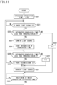
FIG. 11 is a control flowchart of a light source control unit according to a fourth embodiment. A control operation illustrated inFIG. 11 is a fourth embodiment of the control operation of controlling the operation of thelight source 51 of theultraviolet irradiation unit 50. In theair conditioner 10, the light source control unit 52 (seeFIG. 3 ) may control the operation of thelight source 51 along the flow illustrated inFIG. 11 . - As illustrated in
FIG. 11 , when starting the control operation of thelight source 51, the lightsource control unit 52 first executes step (S220), resets an integrated irradiation time T of thelight source 51 to "0", and then executes step (S221). - In step (S221), the light
source control unit 52 determines whether the first signal S1 is input. When determining in step (S211) that the first signal S1 is input (YES), the lightsource control unit 52 subsequently executes step (S222). On the other hand, when determining in step (S221) that the first signal S1 is not input (NO), the lightsource control unit 52 repeatedly executes step (S221) until the first signal S1 is input. - In step (S222), the light
source control unit 52 determines whether the integrated irradiation time T of thelight source 51 is less than a predetermined threshold value Y When determining in step (S222) that the integrated irradiation time T of thelight source 51 is less than the predetermined threshold value Y (YES), the lightsource control unit 52 subsequently executes step (S223). On the other hand, when determining in step (S222) that the integrated irradiation time T of thelight source 51 exceeds the predetermined threshold value Y (NO), the lightsource control unit 52 subsequently executes step (S229). - In step (S223), the light
source control unit 52 turns on the power source of thelight source 51. At this time, in theair conditioner 10, the ultraviolet ray UV is irradiated from thelight source 51 toward thelower end surface 24c of the collectingmember 24. - After turning on the power source of the
light source 51 in step (S223), the lightsource control unit 52 executes step (S224). In step (S224), the lightsource control unit 52 starts integrating the irradiation time of the ultraviolet ray UV by thelight source 51, and then executes step (S225). - In step (S225), the light
source control unit 52 determines whether the integrated irradiation time T of thelight source 51 is less than the predetermined threshold value Y. When determining in step (S225) that the integrated irradiation time T of thelight source 51 is less than the predetermined threshold value Y (YES), the lightsource control unit 52 subsequently executes step (S226). On the other hand, when determining in step (S225) that the integrated irradiation time T of thelight source 51 exceeds the predetermined threshold value Y (NO), the lightsource control unit 52 subsequently executes step (S227). - In step (S227), the light
source control unit 52 resets the integrated irradiation time T of thelight source 51 to "0", and then executes step (S228). - In step (S226), the light
source control unit 52 determines whether the second signal S2 is input. When determining in step (S226) that the second signal S2 is input (YES), the lightsource control unit 52 subsequently executes step (S228). On the other hand, when determining in step (S226) that the second signal S2 is not input (NO), the lightsource control unit 52 repeatedly executes steps (S225) and (S226) until the second signal S2 is input. - In step (S228), the light
source control unit 52 turns off the power source of thelight source 51. After turning off thelight source 51 in step (S228), the lightsource control unit 52 executes step (S230). In steps (S222) to (S229), similarly, the lightsource control unit 52 resets the integrated irradiation time T of thelight source 51 to "0", and then executes step (S230). - In step (S230), the light
source control unit 52 determines whether a timing has come at which the irradiation of the ultraviolet ray UV by of thelight source 51 is possible. When determining in step (S230) that the timing has come at which the irradiation of the ultraviolet ray UV by thelight source 51 is possible (YES), the lightsource control unit 52 returns to step (S221). On the other hand, in step (S230), when determining that the timing has not come at which the irradiation of the ultraviolet ray UV by thelight source 51 is possible (NO), the lightsource control unit 52 repeatedly executes step (S230) until the timing comes at which the irradiation of the ultraviolet ray UV by thelight source 51 is possible. - In the
ultraviolet irradiation unit 50, the upper limit of the irradiation time per day is set in consideration of the life of thelight source 51. When the irradiation time of the ultraviolet ray UV by thelight source 51 does not reach the upper limit on a certain day corresponds to the timing at which the irradiation of the ultraviolet ray UV by thelight source 51 is possible. On the other hand, when the irradiation time of the ultraviolet ray UV by thelight source 51 reaches the upper limit on a certain day corresponds to the timing at which the irradiation of the ultraviolet ray UV by thelight source 51 is impossible. When the irradiation time per day exceeds the upper limit threshold value Y and the light source is turned off after steps (S227) and (S229), the irradiation by the light source cannot be performed on that day, and thus, in step (S230), standby is performed until the next day. - As described above, in the
air conditioner 10 of the present disclosure, the lightsource control unit 52 controls ON and OFF of the power source of thelight source 51 in accordance with the integrated irradiation time T of thelight source 51. -
- (1) The
ultraviolet irradiation unit 50 according to the above embodiment is attachable to theair conditioner 10 including theindoor unit 20 including theindoor fan 22 and the airconditioning control unit 15 that controls the operation of theindoor unit 20. Theultraviolet irradiation unit 50 includes thelight source 51 that irradiates theindoor unit 20 with the ultraviolet ray UV, and the lightsource control unit 52 that is capable of communicating with the airconditioning control unit 15 and controls the operation of thelight source 51. In theultraviolet irradiation unit 50, when receiving the first signal S1 transmitted from the airconditioning control unit 15, the lightsource control unit 52 turns on the power source of thelight source 51.
Theultraviolet irradiation unit 50 having such a configuration eliminates the need for storing in advance a control program for controlling theultraviolet irradiation unit 50 in the airconditioning control unit 15 of theair conditioner 10 to which theultraviolet irradiation unit 50 is attachable. Therefore, the configuration of the airconditioning control unit 15 of theair conditioner 10 can be simplified. - (2) In the
ultraviolet irradiation unit 50 according to the above embodiment, the lightsource control unit 52 turns off the power source of thelight source 51 when the first predetermined period X1 has elapsed after reception of the first signal S1.
In this case, the lightsource control unit 52 can easily turn on and off thelight source 51. The configuration of the lightsource control unit 52 of theultraviolet irradiation unit 50 can be simplified. - (3) In the
ultraviolet irradiation unit 50 according to the above embodiment, the lightsource control unit 52 turns off the power source of thelight source 51 upon reception of the second signal S2 transmitted from the airconditioning control unit 15 when theair conditioner 10 stops operating or when theindoor fan 22 stops operating.
In this case, the lightsource control unit 52 can easily turn on and off thelight source 51 in accordance with the operation state of theair conditioner 10. - (4) The
air conditioner 10 according to the above embodiment includes theindoor unit 20 including thecasing 21 having thesuction port 25 through which indoor air is sucked, theindoor fan 22 accommodated in thecasing 21, and the collectingmember 24 accommodated in thecasing 21, the airconditioning control unit 15 that controls the operation of theindoor unit 20, and theultraviolet irradiation unit 50 including thelight source 51 that irradiates the collectingmember 24 with an ultraviolet ray and the lightsource control unit 52 that is capable of communicating with the airconditioning control unit 15 and controls the operation of thelight source 51. In theair conditioner 10, when receiving the first signal S1 transmitted from the airconditioning control unit 15, the lightsource control unit 52 turns on the power source of thelight source 51.
Theair conditioner 10 of the present disclosure eliminates the need for storing in advance a control program for controlling theultraviolet irradiation unit 50 in the airconditioning control unit 15. Therefore, the configuration of the airconditioning control unit 15 can be simplified in theair conditioner 10. - (5) In the
air conditioner 10 according to the above embodiment, when theair conditioner 10 starts operating or when theindoor fan 22 starts operating, the airconditioning control unit 15 transmits the first signal S1.
In this case, the configuration of the airconditioning control unit 15 can be simplified. - (6) In the
air conditioner 10 according to the above embodiment, the lightsource control unit 52 turns off the power source of thelight source 51 after the first predetermined period X1 elapses following reception of the first signal S1.
In this case, the lightsource control unit 52 can easily turn on and off thelight source 51 in accordance with the operation state of theair conditioner 10. - (7) In the
air conditioner 10 according to the above embodiment, the airconditioning control unit 15 transmits the second signal S2 when theair conditioner 10 stops operating or when theindoor fan 22 stops operating, and the lightsource control unit 52 turns off the power source of thelight source 51 when receiving the second signal S2.
In this case, the configuration of the lightsource control unit 52 can be simplified. - (8) The
air conditioner 10 according to the above embodiment further includes thenotification unit 60. In theair conditioner 10, the airconditioning control unit 15 transmits the third signal S3 to the air conditioning control unit when detecting an abnormality of thelight source 51, and the airconditioning control unit 15 causes thenotification unit 60 to notify when receiving the third signal S3.
In this case, thenotification unit 60 can notify the user that an abnormality has occurred in thelight source 51. - (9) In the
air conditioner 10 according to the above embodiment, the lightsource control unit 52 receives the first information J1 related to an indoor temperature from the airconditioning control unit 15, and the light source control unit turns on and off the power source of thelight source 51 based on the first information J1. - In this case, the light
source control unit 52 having a simple configuration can suppress deterioration of thelight source 51 due to the influence of the ambient temperature. - The embodiments have been described above. Various modifications to modes and details will be available without departing from the gist and the scope of the claims.
-
- 10
- air conditioner
- 15
- air conditioning control unit
- 20
- indoor unit
- 21
- casing
- 22
- indoor fan
- 24
- collecting member
- 25
- suction port
- 50
- ultraviolet irradiation unit
- 51
- light source
- 52
- light source control unit
- 60
- notification unit
- S1
- first signal
- S2
- second signal
- S3
- third signal
- J1
- first information
- X1
- first predetermined period (predetermined period)
Claims (9)
- An ultraviolet irradiation unit (50) attachable to an air conditioner (10) including an indoor unit (20) having an indoor fan (22) and an air conditioning control unit (15) that controls an operation of the indoor unit (20), the ultraviolet irradiation unit (50) comprising:a light source (51) that irradiates the indoor unit (20) with an ultraviolet ray (UV); anda light source control unit (52) that is capable of communicating with the air conditioning control unit (15) and controls an operation of the light source (51), whereinthe light source control unit (52) turns on a power source of the light source (51) when receiving a first signal (S1) transmitted from the air conditioning control unit (15).
- The ultraviolet irradiation unit (50) according to claim 1, wherein the light source control unit (52) turns off the power source of the light source (51) when a predetermined period (X1) has elapsed after reception of the first signal (S1).
- The ultraviolet irradiation unit (50) according to claim 1 or 2, wherein the light source control unit (52) turns off the power source of the light source (51) upon reception of a second signal (S2) transmitted from the air conditioning control unit (15) when the air conditioner (10) stops operating or when the indoor fan (22) stops operating.
- An air conditioner (10) comprising:an indoor unit (20) including a casing (21) having a suction port (25) through which indoor air is sucked, an indoor fan (22) accommodated in the casing (21), and a collecting member (24) accommodated in the casing (21);an air conditioning control unit (15) that controls an operation of the indoor unit (20); andan ultraviolet irradiation unit (50) including a light source (51) that irradiates the collecting member (24) with an ultraviolet ray (UV) and a light source control unit (52) that is capable of communicating with the air conditioning control unit (15) and controls an operation of the light source (51), whereinthe light source control unit (52) turns on a power source of the light source (51) when receiving a first signal (S1) transmitted from the air conditioning control unit (15).
- The air conditioner (10) according to claim 4, whereinwhen the air conditioner (10) starts operating or when the indoor fan (22) starts operating,the air conditioning control unit (15) transmits the first signal (S1).
- The air conditioner (10) according to claim 4 or 5, wherein the light source control unit (52) turns off the power source of the light source (51) after a predetermined period (X1) elapses following reception of the first signal (S1).
- The air conditioner (10) according to any one of claims 4 to 6, whereinthe air conditioning control unit (15) transmits a second signal (S2) when the air conditioner (10) stops operating or when the indoor fan (22) stops operating, andthe light source control unit (52) turns off the power source of the light source (51) when receiving the second signal (S2).
- The air conditioner (10) according to any one of claims 4 to 7, further comprising a notification unit (60), whereinthe light source control unit (52) transmits a third signal (S3) to the air conditioning control unit (15) when detecting an abnormality of the light source (51), andthe air conditioning control unit (15) causes the notification unit (60) to notify when receiving the third signal (S3).
- The air conditioner (10) according to any one of claims 4 to 8, whereinthe light source control unit (52) receives first information (J1) related to an indoor temperature from the air conditioning control unit (15), andthe light source control unit (52) turns on and off the power source of the light source (51) based on the first information (J1).
Applications Claiming Priority (2)
| Application Number | Priority Date | Filing Date | Title |
|---|---|---|---|
| JP2022031524A JP7481636B2 (en) | 2022-03-02 | 2022-03-02 | Ultraviolet irradiation unit and air conditioning device |
| PCT/JP2023/003930 WO2023166924A1 (en) | 2022-03-02 | 2023-02-07 | Ultraviolet radiation unit and air-conditioning device |
Publications (2)
| Publication Number | Publication Date |
|---|---|
| EP4488595A1 true EP4488595A1 (en) | 2025-01-08 |
| EP4488595A4 EP4488595A4 (en) | 2025-07-02 |
Family
ID=87883354
Family Applications (1)
| Application Number | Title | Priority Date | Filing Date |
|---|---|---|---|
| EP23763186.6A Pending EP4488595A4 (en) | 2022-03-02 | 2023-02-07 | Ultraviolet radiation unit and air conditioning device |
Country Status (5)
| Country | Link |
|---|---|
| US (1) | US20240401819A1 (en) |
| EP (1) | EP4488595A4 (en) |
| JP (1) | JP7481636B2 (en) |
| CN (1) | CN118900974B (en) |
| WO (1) | WO2023166924A1 (en) |
Families Citing this family (1)
| Publication number | Priority date | Publication date | Assignee | Title |
|---|---|---|---|---|
| WO2025057264A1 (en) * | 2023-09-11 | 2025-03-20 | 日立ジョンソンコントロールズ空調株式会社 | Air conditioner |
Family Cites Families (16)
| Publication number | Priority date | Publication date | Assignee | Title |
|---|---|---|---|---|
| US5755103A (en) * | 1995-09-16 | 1998-05-26 | Samsung Electronics Co., Ltd. | Room air conditioner with sterilizing apparatus |
| US6849234B2 (en) * | 2001-11-26 | 2005-02-01 | Honeywell International Inc. | System and method for controlling an ultraviolet air treatment device for return air duct applications |
| JP3717852B2 (en) | 2002-01-17 | 2005-11-16 | 三洋電機株式会社 | Ultraviolet lamp unit for air conditioner and air conditioner |
| JP4236531B2 (en) | 2002-09-25 | 2009-03-11 | 三洋電機株式会社 | Air conditioner |
| JP2005207675A (en) | 2004-01-23 | 2005-08-04 | Corona Corp | Air conditioner |
| JP2006038355A (en) | 2004-07-28 | 2006-02-09 | Matsushita Electric Ind Co Ltd | Cleaner equipped with air conditioner |
| KR200406806Y1 (en) | 2005-11-01 | 2006-01-24 | 이승일 | Humidifier with air purification |
| US20160354503A1 (en) * | 2013-12-17 | 2016-12-08 | Oregon Health & Science University | Ultraviolet disinfection of medical device access sites |
| CN105841289A (en) * | 2015-08-24 | 2016-08-10 | 福建福伦德电器有限公司 | Control method of photo-inductive and catalytic clean-type air-conditioning indoor unit |
| KR102414268B1 (en) * | 2016-07-22 | 2022-06-29 | 엘지전자 주식회사 | Air conditioner |
| US11344648B2 (en) * | 2019-02-11 | 2022-05-31 | Ventorlux, Llc | System and method for air purification and sterilization |
| CN110578997A (en) * | 2019-08-13 | 2019-12-17 | 上海朗绿建筑科技股份有限公司 | sterilization control method and system for air treatment unit |
| JP7339522B2 (en) * | 2019-09-30 | 2023-09-06 | ダイキン工業株式会社 | air conditioner |
| JP7014983B1 (en) | 2020-07-14 | 2022-02-15 | ダイキン工業株式会社 | Imaging unit and air processing unit |
| CN113932312A (en) * | 2021-09-27 | 2022-01-14 | 海信(山东)空调有限公司 | Air conditioner indoor unit and ultraviolet sterilization control method |
| CN114110947B (en) * | 2021-11-17 | 2023-04-07 | 海信空调有限公司 | Method of controlling sterilization of air conditioner, and computer-readable storage medium |
-
2022
- 2022-03-02 JP JP2022031524A patent/JP7481636B2/en active Active
-
2023
- 2023-02-07 WO PCT/JP2023/003930 patent/WO2023166924A1/en not_active Ceased
- 2023-02-07 EP EP23763186.6A patent/EP4488595A4/en active Pending
- 2023-02-07 CN CN202380024729.XA patent/CN118900974B/en active Active
-
2024
- 2024-08-12 US US18/800,714 patent/US20240401819A1/en active Pending
Also Published As
| Publication number | Publication date |
|---|---|
| CN118900974B (en) | 2025-03-28 |
| JP7481636B2 (en) | 2024-05-13 |
| JP2023127687A (en) | 2023-09-14 |
| EP4488595A4 (en) | 2025-07-02 |
| US20240401819A1 (en) | 2024-12-05 |
| WO2023166924A1 (en) | 2023-09-07 |
| CN118900974A (en) | 2024-11-05 |
Similar Documents
| Publication | Publication Date | Title |
|---|---|---|
| JP7336595B2 (en) | refrigeration cycle equipment | |
| US11118821B2 (en) | Refrigeration cycle apparatus | |
| ES2968240T3 (en) | Air conditioning system | |
| AU2018422256A1 (en) | Refrigerant leakage determination device, air-conditioning apparatus, and refrigerant leakage determination method | |
| US12059505B2 (en) | Air conditioner | |
| KR102060363B1 (en) | An air conditioner and a method for controlling the same | |
| ES2978484T3 (en) | Air conditioning system | |
| US20240401819A1 (en) | Ultraviolet irradiation unit and air conditioner | |
| CN113218044A (en) | Air conditioner indoor unit, sterilization control method and computer readable storage medium | |
| WO2021050699A1 (en) | Initial power up or power outage refrigerant purge | |
| CN111623422A (en) | Air processor capable of being used as mobile air conditioner | |
| US12111077B2 (en) | Air conditioner unit having a sterilization light assembly | |
| US20240393005A1 (en) | Air conditioner | |
| CN215982895U (en) | Indoor air conditioner | |
| EP4667835A1 (en) | Air conditioner | |
| JP3410860B2 (en) | Air conditioner | |
| US12130049B2 (en) | Air conditioner unit and methods of operation | |
| JP3423209B2 (en) | Heating system | |
| US20240328648A1 (en) | Ventilation system | |
| US12222114B2 (en) | Air conditioner unit having a sterilization light assembly | |
| US11585547B2 (en) | Air conditioner unit having a sterilization light assembly | |
| JPH11173633A (en) | Heating system | |
| KR20240169485A (en) | Air Conditioner | |
| KR20040017118A (en) | One body type central air conditioner for home | |
| JPH1073287A (en) | Air conditioner |
Legal Events
| Date | Code | Title | Description |
|---|---|---|---|
| STAA | Information on the status of an ep patent application or granted ep patent |
Free format text: STATUS: THE INTERNATIONAL PUBLICATION HAS BEEN MADE |
|
| PUAI | Public reference made under article 153(3) epc to a published international application that has entered the european phase |
Free format text: ORIGINAL CODE: 0009012 |
|
| STAA | Information on the status of an ep patent application or granted ep patent |
Free format text: STATUS: REQUEST FOR EXAMINATION WAS MADE |
|
| 17P | Request for examination filed |
Effective date: 20240821 |
|
| AK | Designated contracting states |
Kind code of ref document: A1 Designated state(s): AL AT BE BG CH CY CZ DE DK EE ES FI FR GB GR HR HU IE IS IT LI LT LU LV MC ME MK MT NL NO PL PT RO RS SE SI SK SM TR |
|
| DAV | Request for validation of the european patent (deleted) | ||
| DAX | Request for extension of the european patent (deleted) | ||
| A4 | Supplementary search report drawn up and despatched |
Effective date: 20250530 |
|
| RIC1 | Information provided on ipc code assigned before grant |
Ipc: F24F 1/0071 20190101ALI20250523BHEP Ipc: F24F 11/70 20180101ALI20250523BHEP Ipc: F24F 8/22 20210101ALI20250523BHEP Ipc: F24F 1/0076 20190101ALI20250523BHEP Ipc: F24F 11/63 20180101AFI20250523BHEP |
|
| P01 | Opt-out of the competence of the unified patent court (upc) registered |
Free format text: CASE NUMBER: UPC_APP_3800_4488595/2025 Effective date: 20250820 |
|
| STAA | Information on the status of an ep patent application or granted ep patent |
Free format text: STATUS: EXAMINATION IS IN PROGRESS |
|
| 17Q | First examination report despatched |
Effective date: 20260309 |