EP4488590A1 - Outdoor unit of air conditioner - Google Patents
Outdoor unit of air conditioner Download PDFInfo
- Publication number
- EP4488590A1 EP4488590A1 EP23202391.1A EP23202391A EP4488590A1 EP 4488590 A1 EP4488590 A1 EP 4488590A1 EP 23202391 A EP23202391 A EP 23202391A EP 4488590 A1 EP4488590 A1 EP 4488590A1
- Authority
- EP
- European Patent Office
- Prior art keywords
- orifice
- outdoor unit
- panel
- fastening
- front panel
- Prior art date
- Legal status (The legal status is an assumption and is not a legal conclusion. Google has not performed a legal analysis and makes no representation as to the accuracy of the status listed.)
- Granted
Links
Images



Classifications
-
- F—MECHANICAL ENGINEERING; LIGHTING; HEATING; WEAPONS; BLASTING
- F24—HEATING; RANGES; VENTILATING
- F24F—AIR-CONDITIONING; AIR-HUMIDIFICATION; VENTILATION; USE OF AIR CURRENTS FOR SCREENING
- F24F1/00—Room units for air-conditioning, e.g. separate or self-contained units or units receiving primary air from a central station
- F24F1/06—Separate outdoor units, e.g. outdoor unit to be linked to a separate room comprising a compressor and a heat exchanger
- F24F1/38—Fan details of outdoor units, e.g. bell-mouth shaped inlets or fan mountings
-
- F—MECHANICAL ENGINEERING; LIGHTING; HEATING; WEAPONS; BLASTING
- F04—POSITIVE - DISPLACEMENT MACHINES FOR LIQUIDS; PUMPS FOR LIQUIDS OR ELASTIC FLUIDS
- F04D—NON-POSITIVE-DISPLACEMENT PUMPS
- F04D29/00—Details, component parts, or accessories
- F04D29/40—Casings; Connections of working fluid
- F04D29/52—Casings; Connections of working fluid for axial pumps
- F04D29/522—Casings; Connections of working fluid for axial pumps especially adapted for elastic fluid pumps
- F04D29/526—Details of the casing section radially opposing blade tips
-
- F—MECHANICAL ENGINEERING; LIGHTING; HEATING; WEAPONS; BLASTING
- F04—POSITIVE - DISPLACEMENT MACHINES FOR LIQUIDS; PUMPS FOR LIQUIDS OR ELASTIC FLUIDS
- F04D—NON-POSITIVE-DISPLACEMENT PUMPS
- F04D29/00—Details, component parts, or accessories
- F04D29/40—Casings; Connections of working fluid
- F04D29/52—Casings; Connections of working fluid for axial pumps
- F04D29/54—Fluid-guiding means, e.g. diffusers
- F04D29/541—Specially adapted for elastic fluid pumps
-
- F—MECHANICAL ENGINEERING; LIGHTING; HEATING; WEAPONS; BLASTING
- F24—HEATING; RANGES; VENTILATING
- F24F—AIR-CONDITIONING; AIR-HUMIDIFICATION; VENTILATION; USE OF AIR CURRENTS FOR SCREENING
- F24F1/00—Room units for air-conditioning, e.g. separate or self-contained units or units receiving primary air from a central station
- F24F1/06—Separate outdoor units, e.g. outdoor unit to be linked to a separate room comprising a compressor and a heat exchanger
- F24F1/14—Heat exchangers specially adapted for separate outdoor units
-
- F—MECHANICAL ENGINEERING; LIGHTING; HEATING; WEAPONS; BLASTING
- F24—HEATING; RANGES; VENTILATING
- F24F—AIR-CONDITIONING; AIR-HUMIDIFICATION; VENTILATION; USE OF AIR CURRENTS FOR SCREENING
- F24F1/00—Room units for air-conditioning, e.g. separate or self-contained units or units receiving primary air from a central station
- F24F1/06—Separate outdoor units, e.g. outdoor unit to be linked to a separate room comprising a compressor and a heat exchanger
- F24F1/40—Vibration or noise prevention at outdoor units
-
- F—MECHANICAL ENGINEERING; LIGHTING; HEATING; WEAPONS; BLASTING
- F24—HEATING; RANGES; VENTILATING
- F24F—AIR-CONDITIONING; AIR-HUMIDIFICATION; VENTILATION; USE OF AIR CURRENTS FOR SCREENING
- F24F1/00—Room units for air-conditioning, e.g. separate or self-contained units or units receiving primary air from a central station
- F24F1/06—Separate outdoor units, e.g. outdoor unit to be linked to a separate room comprising a compressor and a heat exchanger
- F24F1/46—Component arrangements in separate outdoor units
- F24F1/48—Component arrangements in separate outdoor units characterised by air airflow, e.g. inlet or outlet airflow
Definitions
- the present disclosure relates to an outdoor unit of an air conditioner.
- An air conditioner is a device that cools and heats an indoor space through heat exchange between a refrigerant flowing through a heat exchange cycle and indoor air and outdoor air.
- the air conditioner includes a compressor that compresses the refrigerant, an outdoor heat exchanger that exchanges heat between the refrigerant and outdoor air, and an indoor heat exchanger that exchanges heat between the refrigerant and indoor air.
- the air conditioner may be equipped with a heat storage tank.
- a fluid heated or cooled by the refrigerant circulating in the air conditioner may be stored.
- the fluid includes water.
- the outdoor unit of the air conditioner includes a case, the compressor accommodated inside the case, the outdoor heat exchanger, and the heat storage tank.
- An orifice is provided on the front surface of the outdoor unit, and a fan is provided between the orifice and the outdoor heat exchanger.
- the fan may be an axial fan.
- the orifice forms a flow path for air forced to flow by the axial fan, and guides the air, which has passed through the outdoor heat exchanger, to flow in the axial direction of the fan and to be discharged to the outside of the outdoor unit.
- Air passing through the orifice generates noise as it passes through the blades of the fan.
- the noise is generated by formation of a vortex in a gap formed between the end of the blade and the inner circumferential surface of the orifice.
- As flow resistance is generated by the vortex there is a disadvantage in that the air that has passed through the outdoor heat exchanger cannot be quickly discharged to the outside of the outdoor unit.
- An outdoor unit of an air conditioner comprises a base panel, a front panel erected on a front end of the base panel and having a through hole formed therein, an orifice fitted to the through hole, a fan placed behind the through hole and having at least a portion accommodated inside the orifice, and a heat exchanger placed on an edge of a rear side of the base panel.
- a front-to-back width of one side end of the orifice is less than that of the other side end of the orifice.
- the heat exchanger may comprise a short side extending along one side end of the base panel and a long side bent from a rear end of the short side and extending along a rear end of the base panel. One end of the orifice may be adjacent to the short side.
- the front-to-rear width of the orifice may increase linearly from one end of the orifice to a center of the orifice.
- the orifice may comprise a cylindrical body, a front extension rounded forward from a front end of the body, a close contact portion extending from a front end of the front extension and coming into close contact with a front surface of the front panel, and a rear extension rounded rearward from a rear end of the body.
- a vortex fence may protrude from an inner circumferential surface of the body to be formed in a band shape.
- a rear surface of the vortex fence may be formed to be rounded with a predetermined curvature.
- An end of a blade forming the fan may be located behind the vortex fence.
- An outer diameter of the blade may be equal to or greater than an inner diameter of the vortex fence
- Coupling guides may be formed on a front surface of the front panel and the close contact portion, respectively.
- the coupling guides may be placed on the same vertical line in a state where the orifice is completely coupled to the front panel.
- a fastening sleeve may extend at the edge of the through hole. At least a portion of the fastening sleeve may be bent to a front side of the front panel.
- the outdoor unit according to the present disclosure may further comprise misassembly prevention ribs formed at upper and lower ends of a back surface of the front panel, respectively, and misassembly prevention grooves formed in upper and lower ends of the fastening sleeve, respectively, to accommodate the misassembly prevention ribs.
- the misassembly prevention ribs and the misassembly prevention grooves may be formed at points spaced to the left or right from a vertical line passing through a center of the through hole.
- the outdoor unit according to the present disclosure may further comprise fastening hooks protruding from a back surface of the close contact portion, and hook grooves formed in the fastening sleeve to accommodate the fastening hooks.
- fastening hooks protruding from a back surface of the close contact portion, and hook grooves formed in the fastening sleeve to accommodate the fastening hooks.
- the fastening hooks may protrude from left and right sides of a back surface of the close contact portion, respectively, the hook grooves may be formed in left and right sides of the fastening sleeve, respectively.
- the pair of fastening hooks may be formed symmetrically with respect to a horizontal plane.
- the outdoor unit of the air conditioner according to the embodiment of the present disclosure configured as described above has the following effects.
- the cross-section of the orifice has an asymmetric structure, which has the effect of increasing air volume.
- a vortex fence that suppresses vortex generation protrudes from the inner circumferential surface of the orifice, which has the effect of increasing air volume and reducing noise.
- FIG. 1 is a perspective view of an outdoor unit configuring an air conditioner equipped with a heat storage tank.
- the outdoor unit 10 of the air conditioner includes a base panel 11, a front panel 12 built on a front end of the base panel 11, an orifice 13 coupled to the front panel 12, a fan 15 placed behind the orifice 13, and a heat exchanger 14 built on an upper surface of the base panel 11.
- the outdoor unit 10 further includes a barrier 16 built on the upper surface of the base panel 11.
- the barrier 16 may be understood as a partition member that partitions an upper space of the base panel 11 into a heat exchange space on the left and an electrical equipment space on the right.
- the heat exchanger 14 is erected in the heat exchange space and is bent and extended along the side and rear ends of the base panel 11 to define the side and rear surfaces of the heat exchange space.
- One side end of the front panel 12 may be coupled to the front end of the heat exchanger 14, and the other side end may be coupled to the front end of the barrier 16.
- the rear end of the barrier 16 may be connected to the side end of the heat exchanger 14.
- the outdoor unit 10 may further include a compressor 19 standing on the upper surface of the base panel 11 corresponding to the electrical equipment space, a heat storage tank 20, and a control box 17 placed in the upper space of the heat storage tank 20.
- the heat storage tank 20 may be placed at a location spaced apart from the compressor 19, and a flow path is provided inside the heat storage tank 20 to enable heat exchange between the refrigerant and water without mixing.
- Air which has passed through the heat exchanger 14, flows from the rear surface of the fan 15 toward the front surface, passes through the orifice 13, and is then discharged to the outside of the outdoor unit 10.
- Some of a plurality of blades constituting the fan 15 are accommodated inside the orifice 13 so that all air forced to flow by the fan 15 passes through the orifice 13.
- FIG. 2 is an exploded perspective view showing a state of coupling an orifice and a front panel
- FIG. 3 is a rear view of the orifice.
- the front panel 12 to which the orifice 13 is coupled includes a panel body 121 in the form of a rectangular plate, and the panel body 121 has a through hole 1201 formed therein. Then, the orifice 13 is fitted into and coupled to the through hole 1201.
- a fastening sleeve 122 for fastening the orifice 13 extends at an edge of the through hole 1201.
- the fastening sleeve 122 is bent to the front side of the front panel 12 and contacts the side surface of the orifice 13.
- a plurality of fastening steps 1222 are formed in the fastening sleeve 122, and a screw hole 1223 is formed in each fastening step 1222.
- the plurality of fastening steps 1222 may be formed on the upper left and right sides and lower left and right sides, respectively, based on a vertical line bisecting the through hole 1201 into left and right sides.
- a misassembly prevention groove 1224 may be formed in the fastening sleeve 122 corresponding to a space between adjacent fastening steps, and the misassembly prevention groove 1224 may be formed in the upper and lower ends of the fastening sleeve 122.
- the pair of misassembly prevention grooves 1224 are formed in the left or right side of a vertical line bisecting the through hole 1201.
- one or more hook grooves 1221 may be formed in the fastening sleeve 122.
- the hook grooves 1221 may be formed at positions facing each other on the left and right sides of the through hole 1201.
- a coupling guide 1226 may be formed on the front surface of the front panel 12.
- the coupling guide 1226 functions to guide the orifice 13 to be correctly coupled to a correct position, and may be formed at any point between an upper end of the through hole 1201 and an upper end of the panel body 121.
- the coupling guide 1226 may have an inverted triangle shape, and a portion of the panel body 121 may be formed to protrude forward by a forming process.
- the orifice 13 includes a panel seating portion 131 in close contact with the front surface of the front panel 15, a diffuser 132 rounded backward from the panel seating portion 131, an inducer 134 extending roundly backward from the rear end of the diffuser 132, and a vortex fence 133 surrounding the inner circumferential surface of the orifice 13 corresponding to a boundary between the diffuser 132 and the inducer 134.
- the rear end of the inducer 134 may be defined as the rear end of the orifice 13
- the panel seating portion 131 may be defined as the front surface of the orifice 13.
- the diffuser 132 may be composed of a round portion rounded such that a diameter becomes smaller rearward from the rear end of the panel seating part 131, and a straight portion extending rearward from the rear end of the round portion.
- the inducer 134 may be composed of a straight portion extending rearward from the straight portion of the diffuser 132 and a round portion that is rounded in a direction in which the diameter increases rearward from the rear end of the straight portion.
- the orifice 13 may be described as including a cylindrical body portion, a front extension that is rounded forward from the front end of the body, a rear extension that is rounded rearward from the rear end of the body, and a close contact portion that extends from the front end of the front extension and comes into close contact with the front surface of the front panel 12.
- the vortex fence 133 may be described as protruding from the inner circumferential surface of the body and surrounding it in a band shape.
- a plurality of reinforcing ribs 136 may be formed to protrude from the outer circumferential surface of the orifice 13.
- the plurality of reinforcing ribs 136 may be arranged to be spaced apart in the circumferential direction of the orifice 13.
- fastening hooks 135 protrude from a back surface of the panel seating portion 131.
- the fastening hooks 135 are inserted into the hook grooves 1221 of the front panel 12. Accordingly, the fastening hooks 135 may also be formed on the left and right sides of the orifice 13, respectively.
- a plurality of fastening steps 137 may be formed in the front surface of the orifice 13, and a screw hole 1371 is formed in each fastening step 137.
- the plurality of fastening steps 137 may be formed at positions corresponding to the plurality of fastening steps 1222 formed on the front panel 12, respectively. That is, the plurality of fastening steps 137 may be formed on the left and right sides of the front upper and lower ends of the orifice 13, respectively.
- a coupling guide 138 may be formed at the upper end of the panel seating portion 131.
- the coupling guide 138 may be formed at a position facing the coupling guide 1226 formed on the front panel 12, and may have an equilateral triangle shape, but is not limited thereto.
- the coupling guides 138 and 1226 are placed on the same vertical line.
- the combination guides 138 and 1226 prevent the upper and lower surfaces of the orifice 13 from being reversed and combined. More specifically, since the left and right portions of the orifice 13 according to the present disclosure form an asymmetrical shape, there is a limitation in that the upper and lower portions are not reversed and combined. To prevent such misassembly, the coupling guides 138 and 1226 are provided.
- misassembly prevention ribs may be formed on the back surface of the orifice 13.
- the misassembly prevention ribs include an upper misassembly prevention rib 1391 formed on the upper side of the back surface of the orifice 13 and a lower misassembly prevention rib 1392 formed on the lower side of the back surface.
- the upper and lower misassembly prevention ribs 1391 and 1392 are respectively fitted into the upper and lower misassembly prevention grooves 1224 and 1225 of the front panel 12. Accordingly, the upper and lower misassembly prevention ribs 1391 and 1392 may also be formed at points spaced to the left or right from a vertical line bisecting the orifice 13.
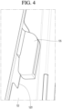
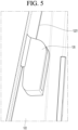
- FIGS. 4 and 5 are enlarged views of a portion A of FIG. 1 , showing a state where the fastening hook of the orifice is inserted into the hook groove of the front panel.
- the fastening hooks 135 are formed on the left and right sides of the orifice 13, respectively, and are formed symmetrically with respect to a horizontal line. That is, the fastening hook 135 on the right may extend downward clockwise in the drawing, and the fastening hook 135 on the left may extend upward clockwise.
- the structure of the fastening hook 135 and the hook groove 1221 may reduce the number of fastening steps 1222 and 137 for screw coupling, thereby shortening an assembly time and reducing manufacturing costs.
- FIG. 6 is a cross-sectional view of the orifice taken along line 6-6 of FIG. 2 .
- the left and right ends of the orifice 13 according to the present disclosure are designed to have different widths in the front-to-back direction.
- the left portion of the orifice 13 adjacent to the short side of the heat exchanger 14 and the right portion of the orifice 13 adjacent to the barrier 16 are designed to have different shapes.
- the width of the left portion of the orifice 13 adjacent to the short side of the heat exchanger 14 increases, when outside air sucked through the short side of the heat exchanger 14 may flow into the orifice 13, there is a disadvantage that flow resistance increases.
- the front-to-back width L2 of the right portion of the orifice 13 is designed to be larger than the front-to-back width L1 of the left portion of the orifice 13.
- the left rear end of the orifice 13 is formed to be tapered so that the front-to-back width increases linearly from the left end of the orifice 13 to the center of the orifice 13, as shown.
- the right rear end of 13 of the orifice 13 is formed parallel to the front surface of the orifice 13.
- FIG. 7 is an enlarged cross-sectional view of a portion B of FIG. 1 .
- the fan 15 is provided in a form in which some of the blades are accommodated inside the orifice 13, so that all air flowing by the fan 15 passes through the orifice 13.
- the blade of the fan 15 is located at the rear side of the vortex fence 133, and the outer diameter R2 of the blade may be designed to be larger than or equal to the inner diameter R1 of the vortex fence 133.
- the vortex fence 133 includes a straight portion 1331 extending radially from the inner circumferential surface of the orifice 13, and a round portion 1332 rounded from the upper end of the straight portion 1331 toward the inner circumferential surface of the orifice 13. Then, the sucked air passes over the round portion 1332 and is discharged to the front side of the outdoor unit 10.
Landscapes
- Engineering & Computer Science (AREA)
- Mechanical Engineering (AREA)
- General Engineering & Computer Science (AREA)
- Chemical & Material Sciences (AREA)
- Combustion & Propulsion (AREA)
- Other Air-Conditioning Systems (AREA)
Abstract
Description
- The present application claims the benefits of priority to
Korean Patent Application No. 10-2023-0086994, filed on July 05, 2023 - The present disclosure relates to an outdoor unit of an air conditioner.
- An air conditioner is a device that cools and heats an indoor space through heat exchange between a refrigerant flowing through a heat exchange cycle and indoor air and outdoor air.
- Specifically, the air conditioner includes a compressor that compresses the refrigerant, an outdoor heat exchanger that exchanges heat between the refrigerant and outdoor air, and an indoor heat exchanger that exchanges heat between the refrigerant and indoor air.
- The air conditioner may be equipped with a heat storage tank. In the heat storage tank, a fluid heated or cooled by the refrigerant circulating in the air conditioner may be stored. In one example, the fluid includes water.
- The outdoor unit of the air conditioner includes a case, the compressor accommodated inside the case, the outdoor heat exchanger, and the heat storage tank.
- An orifice is provided on the front surface of the outdoor unit, and a fan is provided between the orifice and the outdoor heat exchanger. The fan may be an axial fan. The orifice forms a flow path for air forced to flow by the axial fan, and guides the air, which has passed through the outdoor heat exchanger, to flow in the axial direction of the fan and to be discharged to the outside of the outdoor unit.
- Air passing through the orifice generates noise as it passes through the blades of the fan. The noise is generated by formation of a vortex in a gap formed between the end of the blade and the inner circumferential surface of the orifice. As flow resistance is generated by the vortex, there is a disadvantage in that the air that has passed through the outdoor heat exchanger cannot be quickly discharged to the outside of the outdoor unit.
- The invention is specified by the independent claim. Preferred embodiments are defined in the dependent claims. The present disclosure is proposed to improve the above problems.
- An outdoor unit of an air conditioner according to an embodiment of the present disclosure comprises a base panel, a front panel erected on a front end of the base panel and having a through hole formed therein, an orifice fitted to the through hole, a fan placed behind the through hole and having at least a portion accommodated inside the orifice, and a heat exchanger placed on an edge of a rear side of the base panel. A front-to-back width of one side end of the orifice is less than that of the other side end of the orifice.
- The heat exchanger may comprise a short side extending along one side end of the base panel and a long side bent from a rear end of the short side and extending along a rear end of the base panel. One end of the orifice may be adjacent to the short side. The front-to-rear width of the orifice may increase linearly from one end of the orifice to a center of the orifice.
- The orifice may comprise a cylindrical body, a front extension rounded forward from a front end of the body, a close contact portion extending from a front end of the front extension and coming into close contact with a front surface of the front panel, and a rear extension rounded rearward from a rear end of the body. A vortex fence may protrude from an inner circumferential surface of the body to be formed in a band shape.
- A rear surface of the vortex fence may be formed to be rounded with a predetermined curvature.
- An end of a blade forming the fan may be located behind the vortex fence. An outer diameter of the blade may be equal to or greater than an inner diameter of the vortex fence
- Coupling guides may be formed on a front surface of the front panel and the close contact portion, respectively. The coupling guides may be placed on the same vertical line in a state where the orifice is completely coupled to the front panel.
- A fastening sleeve may extend at the edge of the through hole. At least a portion of the fastening sleeve may be bent to a front side of the front panel.
- The outdoor unit according to the present disclosure may further comprise misassembly prevention ribs formed at upper and lower ends of a back surface of the front panel, respectively, and misassembly prevention grooves formed in upper and lower ends of the fastening sleeve, respectively, to accommodate the misassembly prevention ribs. The misassembly prevention ribs and the misassembly prevention grooves may be formed at points spaced to the left or right from a vertical line passing through a center of the through hole.
- The outdoor unit according to the present disclosure may further comprise fastening hooks protruding from a back surface of the close contact portion, and hook grooves formed in the fastening sleeve to accommodate the fastening hooks. When the orifice rotates in a state of being in close contact with the front panel, the fastening hooks are caught in the hook grooves.
- The fastening hooks may protrude from left and right sides of a back surface of the close contact portion, respectively, the hook grooves may be formed in left and right sides of the fastening sleeve, respectively. The pair of fastening hooks may be formed symmetrically with respect to a horizontal plane.
- The outdoor unit of the air conditioner according to the embodiment of the present disclosure configured as described above has the following effects.
- First, the cross-section of the orifice has an asymmetric structure, which has the effect of increasing air volume.
- Second, a vortex fence that suppresses vortex generation protrudes from the inner circumferential surface of the orifice, which has the effect of increasing air volume and reducing noise.
- Third, by improving an assembly structure between the orifice and a front panel, there is an advantage in reducing the number of screws to secure the orifice to the front panel.
- Fourth, there is an advantage in preventing misassembly of the orifice by providing a misassembly prevention unit to prevent the orifice having an asymmetric shape from being incorrectly assembled on the front panel.
-
-
FIG. 1 is a perspective view of an outdoor unit configuring an air conditioner equipped with a heat storage tank. -
FIG. 2 is an exploded perspective view showing a state of coupling an orifice and a front panel. -
FIG. 3 is a rear view of the orifice. -
FIGS. 4 and5 are enlarged views of a portion A ofFIG. 1 , showing a state where a fastening hook of the orifice is inserted into a hook groove of the front panel. -
FIG. 6 is a cross-sectional view of the orifice taken along line 6-6 ofFIG. 2 . -
FIG. 7 is an enlarged cross-sectional view of a portion B ofFIG. 1 . - Hereinafter, an outdoor unit of an air conditioner according to an embodiment of the present disclosure will be described in detail with reference to the drawings.
-
FIG. 1 is a perspective view of an outdoor unit configuring an air conditioner equipped with a heat storage tank. - Referring to
FIG. 1 , theoutdoor unit 10 of the air conditioner according to the embodiment of the present disclosure includes abase panel 11, afront panel 12 built on a front end of thebase panel 11, anorifice 13 coupled to thefront panel 12, afan 15 placed behind theorifice 13, and aheat exchanger 14 built on an upper surface of thebase panel 11. - Specifically, the
outdoor unit 10 further includes abarrier 16 built on the upper surface of thebase panel 11. - The
barrier 16 may be understood as a partition member that partitions an upper space of thebase panel 11 into a heat exchange space on the left and an electrical equipment space on the right. In addition, theheat exchanger 14 is erected in the heat exchange space and is bent and extended along the side and rear ends of thebase panel 11 to define the side and rear surfaces of the heat exchange space. - One side end of the
front panel 12 may be coupled to the front end of theheat exchanger 14, and the other side end may be coupled to the front end of thebarrier 16. The rear end of thebarrier 16 may be connected to the side end of theheat exchanger 14. - The
outdoor unit 10 may further include acompressor 19 standing on the upper surface of thebase panel 11 corresponding to the electrical equipment space, aheat storage tank 20, and acontrol box 17 placed in the upper space of theheat storage tank 20. - The
heat storage tank 20 may be placed at a location spaced apart from thecompressor 19, and a flow path is provided inside theheat storage tank 20 to enable heat exchange between the refrigerant and water without mixing. - When the
fan 15 rotates, outside air flows into theoutdoor unit 10 through the short side of theheat exchanger 14 forming the side surface of theoutdoor unit 10 and the long side of theheat exchanger 14 forming the rear surface of theoutdoor unit 10. - Air, which has passed through the
heat exchanger 14, flows from the rear surface of thefan 15 toward the front surface, passes through theorifice 13, and is then discharged to the outside of theoutdoor unit 10. - Some of a plurality of blades constituting the
fan 15 are accommodated inside theorifice 13 so that all air forced to flow by thefan 15 passes through theorifice 13. -
FIG. 2 is an exploded perspective view showing a state of coupling an orifice and a front panel, andFIG. 3 is a rear view of the orifice. - Referring to
FIGS. 2 and3 , thefront panel 12 to which theorifice 13 is coupled includes apanel body 121 in the form of a rectangular plate, and thepanel body 121 has a throughhole 1201 formed therein. Then, theorifice 13 is fitted into and coupled to the throughhole 1201. - Specifically, a
fastening sleeve 122 for fastening theorifice 13 extends at an edge of the throughhole 1201. Thefastening sleeve 122 is bent to the front side of thefront panel 12 and contacts the side surface of theorifice 13. - In addition, a plurality of
fastening steps 1222 are formed in thefastening sleeve 122, and ascrew hole 1223 is formed in eachfastening step 1222. The plurality offastening steps 1222 may be formed on the upper left and right sides and lower left and right sides, respectively, based on a vertical line bisecting the throughhole 1201 into left and right sides. - In addition, a
misassembly prevention groove 1224 may be formed in thefastening sleeve 122 corresponding to a space between adjacent fastening steps, and themisassembly prevention groove 1224 may be formed in the upper and lower ends of thefastening sleeve 122. In addition, the pair ofmisassembly prevention grooves 1224 are formed in the left or right side of a vertical line bisecting the throughhole 1201. - In addition, one or
more hook grooves 1221 may be formed in thefastening sleeve 122. For example, thehook grooves 1221 may be formed at positions facing each other on the left and right sides of the throughhole 1201. - In addition, a
coupling guide 1226 may be formed on the front surface of thefront panel 12. Thecoupling guide 1226 functions to guide theorifice 13 to be correctly coupled to a correct position, and may be formed at any point between an upper end of the throughhole 1201 and an upper end of thepanel body 121. Thecoupling guide 1226 may have an inverted triangle shape, and a portion of thepanel body 121 may be formed to protrude forward by a forming process. - Meanwhile, the
orifice 13 includes apanel seating portion 131 in close contact with the front surface of thefront panel 15, adiffuser 132 rounded backward from thepanel seating portion 131, aninducer 134 extending roundly backward from the rear end of thediffuser 132, and avortex fence 133 surrounding the inner circumferential surface of theorifice 13 corresponding to a boundary between thediffuser 132 and theinducer 134. - Specifically, the rear end of the
inducer 134 may be defined as the rear end of theorifice 13, and thepanel seating portion 131 may be defined as the front surface of theorifice 13. In addition, thediffuser 132 may be composed of a round portion rounded such that a diameter becomes smaller rearward from the rear end of thepanel seating part 131, and a straight portion extending rearward from the rear end of the round portion. - In addition, the
inducer 134 may be composed of a straight portion extending rearward from the straight portion of thediffuser 132 and a round portion that is rounded in a direction in which the diameter increases rearward from the rear end of the straight portion. - By this structure, the
orifice 13 may be described as including a cylindrical body portion, a front extension that is rounded forward from the front end of the body, a rear extension that is rounded rearward from the rear end of the body, and a close contact portion that extends from the front end of the front extension and comes into close contact with the front surface of thefront panel 12. In addition, thevortex fence 133 may be described as protruding from the inner circumferential surface of the body and surrounding it in a band shape. - A plurality of reinforcing
ribs 136 may be formed to protrude from the outer circumferential surface of theorifice 13. The plurality of reinforcingribs 136 may be arranged to be spaced apart in the circumferential direction of theorifice 13. - In addition, fastening hooks 135 protrude from a back surface of the
panel seating portion 131. The fastening hooks 135 are inserted into thehook grooves 1221 of thefront panel 12. Accordingly, the fastening hooks 135 may also be formed on the left and right sides of theorifice 13, respectively. - A plurality of
fastening steps 137 may be formed in the front surface of theorifice 13, and ascrew hole 1371 is formed in eachfastening step 137. The plurality offastening steps 137 may be formed at positions corresponding to the plurality offastening steps 1222 formed on thefront panel 12, respectively. That is, the plurality offastening steps 137 may be formed on the left and right sides of the front upper and lower ends of theorifice 13, respectively. - A
coupling guide 138 may be formed at the upper end of thepanel seating portion 131. - The
coupling guide 138 may be formed at a position facing thecoupling guide 1226 formed on thefront panel 12, and may have an equilateral triangle shape, but is not limited thereto. - Specifically, when the
orifice 13 is completely coupled to thefront panel 12, the coupling guides 138 and 1226 are placed on the same vertical line. The combination guides 138 and 1226 prevent the upper and lower surfaces of theorifice 13 from being reversed and combined. More specifically, since the left and right portions of theorifice 13 according to the present disclosure form an asymmetrical shape, there is a limitation in that the upper and lower portions are not reversed and combined. To prevent such misassembly, the coupling guides 138 and 1226 are provided. - As an additional unit for preventing misassembly, misassembly prevention ribs may be formed on the back surface of the
orifice 13. The misassembly prevention ribs include an uppermisassembly prevention rib 1391 formed on the upper side of the back surface of theorifice 13 and a lowermisassembly prevention rib 1392 formed on the lower side of the back surface. The upper and lowermisassembly prevention ribs misassembly prevention grooves front panel 12. Accordingly, the upper and lowermisassembly prevention ribs orifice 13. -
FIGS. 4 and5 are enlarged views of a portion A ofFIG. 1 , showing a state where the fastening hook of the orifice is inserted into the hook groove of the front panel. - Referring to
FIG. 4 , the fastening hooks 135 are formed on the left and right sides of theorifice 13, respectively, and are formed symmetrically with respect to a horizontal line. That is, thefastening hook 135 on the right may extend downward clockwise in the drawing, and thefastening hook 135 on the left may extend upward clockwise. - Specifically, when the
orifice 13 is in close contact with the front surface of thefront panel 12, the lower end of thefastening hook 135 is fitted into thehook groove 1221. In this state, when theorifice 13 rotates clockwise, thefastening hook 135 on the right side rotates from the upper end to the lower end of thehook groove 1221 and is caught in the lower end of thehook groove 1221. Conversely, thefastening hook 135 on the left rotates from the lower end to the upper end of thehook groove 1221 and is caught in the upper end of thehook groove 1221. - The structure of the
fastening hook 135 and thehook groove 1221 may reduce the number offastening steps -
FIG. 6 is a cross-sectional view of the orifice taken along line 6-6 ofFIG. 2 . - Referring to
Figure 6 , the left and right ends of theorifice 13 according to the present disclosure are designed to have different widths in the front-to-back direction. - Specifically, the left portion of the
orifice 13 adjacent to the short side of theheat exchanger 14 and the right portion of theorifice 13 adjacent to thebarrier 16 are designed to have different shapes. - More specifically, the larger the front-to-back width of the
orifice 13 is, the larger the area for accommodating the blades of thefan 15 is, which has the advantage of increasing air volume. However, if the width of the left portion of theorifice 13 adjacent to the short side of theheat exchanger 14 increases, when outside air sucked through the short side of theheat exchanger 14 may flow into theorifice 13, there is a disadvantage that flow resistance increases. In order to overcome this problem, the front-to-back width L2 of the right portion of theorifice 13 is designed to be larger than the front-to-back width L1 of the left portion of theorifice 13. - Accordingly, the left rear end of the
orifice 13 is formed to be tapered so that the front-to-back width increases linearly from the left end of theorifice 13 to the center of theorifice 13, as shown. The right rear end of 13 of theorifice 13 is formed parallel to the front surface of theorifice 13. -
FIG. 7 is an enlarged cross-sectional view of a portion B ofFIG. 1 . - Referring to
FIG. 7 , thefan 15 is provided in a form in which some of the blades are accommodated inside theorifice 13, so that all air flowing by thefan 15 passes through theorifice 13. - Specifically, the blade of the
fan 15 is located at the rear side of thevortex fence 133, and the outer diameter R2 of the blade may be designed to be larger than or equal to the inner diameter R1 of thevortex fence 133. - As the sucked air passes through a gap formed between the end of the blade and the inner circumferential surface of the
orifice 13, a vortex is formed. As thevortex fence 133 protrudes, formation of the vortex is suppressed, the air volume increases, and noise is reduced. - The
vortex fence 133 includes astraight portion 1331 extending radially from the inner circumferential surface of theorifice 13, and around portion 1332 rounded from the upper end of thestraight portion 1331 toward the inner circumferential surface of theorifice 13. Then, the sucked air passes over theround portion 1332 and is discharged to the front side of theoutdoor unit 10.
Claims (15)
- An outdoor unit (10) of an air conditioner comprising:a base panel (11);a front panel (12) erected on a front end of the base panel (11) and having a through hole formed therein;an orifice (13) fitted to the through hole;a fan (15) placed behind the through hole and having at least a portion accommodated inside the orifice (13); anda heat exchanger (14) placed on an edge of a rear side of the base panel (11),wherein a front-to-back width of one side end of the orifice (13) is less than that of the other side end of the orifice (13).
- The outdoor unit (10) of claim 1,wherein the heat exchanger (14) comprises:a short side extending along one side end of the base panel (11); anda long side bent from a rear end of the short side and extending along a rear end of the base panel (11),wherein one end of the orifice (13) is adjacent to the short side, andwherein the front-to-rear width of the orifice (13) increases linearly from one end of the orifice (13) to a center of the orifice (13).
- The outdoor unit of claim 1 or 2,wherein the orifice (13) comprises:a cylindrical body;a front extension rounded forward from a front end of the body;a close contact portion extending from a front end of the front extension and coming into close contact with a front surface of the front panel (12); anda rear extension rounded rearward from a rear end of the body,wherein a vortex fence (133) protrudes from an inner circumferential surface of the body to be formed in a band shape.
- The outdoor unit of claim 3,
wherein a rear surface of the vortex fence (133) is formed to be rounded with a predetermined curvature. - The outdoor unit of claim 3 or 4,
wherein an end of a blade forming the fan (15) is located behind the vortex fence (133). - The outdoor unit of claim 5,
wherein an outer diameter (R2) of the blade is equal to or greater than an inner diameter (R1) of the vortex fence (133). - The outdoor unit according to any one of claims 3 to 6,
wherein coupling guides (1226) are formed on a front surface of the front panel (12) and the close contact portion, respectively. - The outdoor unit of claim 7,
wherein the coupling guides (1226) are placed on the same vertical line in a state where the orifice (13) is completely coupled to the front panel (12). - The outdoor unit according to any one of claims 3 to 8,
wherein a fastening sleeve (122) extends at the edge of the through hole (1201). - The outdoor unit of claim 9,
wherein at least a portion of the fastening sleeve (122) is bent to a front side of the front panel (12). - The outdoor unit of claim 9 or 10, further comprising:misassembly prevention ribs (1391, 1392) formed at upper and lower ends of a back surface of the front panel (12), respectively; andmisassembly prevention grooves (1224, 1225) formed in upper and lower ends of the fastening sleeve (122), respectively, to accommodate the misassembly prevention ribs (1391, 1392).
- The outdoor unit of claim 11,
wherein the misassembly prevention ribs (1391, 1392) and the misassembly prevention grooves (1224, 1225) are formed at points spaced to the left or right from a vertical line passing through a center of the through hole (1201). - The outdoor unit according to any one of claims 9 to 12, further comprising:fastening hooks (135) protruding from a back surface of the close contact portion; andhook grooves (1221) formed in the fastening sleeve (122) to accommodate the fastening hooks (135),wherein when the orifice (13) rotates in a state of being in close contact with the front panel (12), the fastening hooks (135) are caught in the hook grooves (1221).
- The outdoor unit of claim 13,wherein the fastening hooks (135) protrude from left and right sides of a back surface of the close contact portion, respectively,wherein the hook grooves (1221) are formed in left and right sides of the fastening sleeve (122), respectively.
- The outdoor unit of claim 14,
wherein the pair of fastening hooks (135) is formed symmetrically with respect to a horizontal plane.
Applications Claiming Priority (1)
| Application Number | Priority Date | Filing Date | Title |
|---|---|---|---|
| KR1020230086994A KR102808316B1 (en) | 2023-07-05 | 2023-07-05 | An outdoor unit of air conditioner |
Publications (3)
| Publication Number | Publication Date |
|---|---|
| EP4488590A1 true EP4488590A1 (en) | 2025-01-08 |
| EP4488590B1 EP4488590B1 (en) | 2025-08-13 |
| EP4488590C0 EP4488590C0 (en) | 2025-08-13 |
Family
ID=88297082
Family Applications (1)
| Application Number | Title | Priority Date | Filing Date |
|---|---|---|---|
| EP23202391.1A Active EP4488590B1 (en) | 2023-07-05 | 2023-10-09 | Outdoor unit of air conditioner |
Country Status (3)
| Country | Link |
|---|---|
| US (1) | US12405014B2 (en) |
| EP (1) | EP4488590B1 (en) |
| KR (1) | KR102808316B1 (en) |
Citations (6)
| Publication number | Priority date | Publication date | Assignee | Title |
|---|---|---|---|---|
| KR20070046463A (en) * | 2005-10-31 | 2007-05-03 | 삼성전자주식회사 | Outdoor unit of air conditioner |
| JP2009203980A (en) * | 2008-01-31 | 2009-09-10 | Daikin Ind Ltd | Air blower, outdoor unit, air conditioner and method of manufacturing air blower |
| WO2009113338A1 (en) * | 2008-03-11 | 2009-09-17 | 三菱電機株式会社 | Air conditioner |
| JP4690682B2 (en) * | 2004-09-07 | 2011-06-01 | 三菱電機株式会社 | air conditioner |
| KR20200043847A (en) * | 2018-10-18 | 2020-04-28 | 엘지전자 주식회사 | Air conditioner and orifice applied to it |
| US20230142460A1 (en) * | 2020-06-12 | 2023-05-11 | Mitsubishi Electric Corporation | Outdoor unit for air-conditioning apparatus |
Family Cites Families (13)
| Publication number | Priority date | Publication date | Assignee | Title |
|---|---|---|---|---|
| JP4190683B2 (en) * | 1999-11-22 | 2008-12-03 | 株式会社小松製作所 | Fan device |
| ATE444448T1 (en) * | 2006-05-31 | 2009-10-15 | Bosch Gmbh Robert | AXIAL FAN ARRANGEMENT |
| JP4903119B2 (en) | 2007-06-25 | 2012-03-28 | 三菱電機株式会社 | Gas-liquid separator and air conditioner equipped with it |
| US9212695B2 (en) | 2011-06-01 | 2015-12-15 | Thomson Industries Inc. | Hybrid clam-shell linear bearing |
| JP5549686B2 (en) * | 2012-01-12 | 2014-07-16 | 株式会社デンソー | Blower |
| JP6340819B2 (en) * | 2014-02-21 | 2018-06-13 | 株式会社デンソー | Blower |
| JP6394409B2 (en) * | 2015-01-19 | 2018-09-26 | 株式会社デンソー | Blower |
| US9683580B2 (en) * | 2015-05-05 | 2017-06-20 | Ford Global Technologies, Llc | Hinge interface for two-piece fan shroud |
| KR101734722B1 (en) | 2015-12-14 | 2017-05-11 | 엘지전자 주식회사 | Orifice for airconditioner |
| JP6493427B2 (en) * | 2016-05-11 | 2019-04-03 | 株式会社デンソー | Fan shroud |
| KR101996052B1 (en) * | 2016-11-01 | 2019-07-03 | 엘지전자 주식회사 | Air conditioner |
| US11181125B2 (en) * | 2018-04-23 | 2021-11-23 | Asia Vital Components Co., Ltd. | Fan frame body with damping structure and fan thereof |
| KR102423747B1 (en) * | 2020-12-03 | 2022-07-22 | 엘지전자 주식회사 | An outdoor unit of an air conditioner |
-
2023
- 2023-07-05 KR KR1020230086994A patent/KR102808316B1/en active Active
- 2023-10-09 EP EP23202391.1A patent/EP4488590B1/en active Active
- 2023-11-06 US US18/502,311 patent/US12405014B2/en active Active
Patent Citations (6)
| Publication number | Priority date | Publication date | Assignee | Title |
|---|---|---|---|---|
| JP4690682B2 (en) * | 2004-09-07 | 2011-06-01 | 三菱電機株式会社 | air conditioner |
| KR20070046463A (en) * | 2005-10-31 | 2007-05-03 | 삼성전자주식회사 | Outdoor unit of air conditioner |
| JP2009203980A (en) * | 2008-01-31 | 2009-09-10 | Daikin Ind Ltd | Air blower, outdoor unit, air conditioner and method of manufacturing air blower |
| WO2009113338A1 (en) * | 2008-03-11 | 2009-09-17 | 三菱電機株式会社 | Air conditioner |
| KR20200043847A (en) * | 2018-10-18 | 2020-04-28 | 엘지전자 주식회사 | Air conditioner and orifice applied to it |
| US20230142460A1 (en) * | 2020-06-12 | 2023-05-11 | Mitsubishi Electric Corporation | Outdoor unit for air-conditioning apparatus |
Also Published As
| Publication number | Publication date |
|---|---|
| US12405014B2 (en) | 2025-09-02 |
| KR20250007186A (en) | 2025-01-14 |
| EP4488590B1 (en) | 2025-08-13 |
| US20250012459A1 (en) | 2025-01-09 |
| EP4488590C0 (en) | 2025-08-13 |
| KR102808316B1 (en) | 2025-05-15 |
Similar Documents
| Publication | Publication Date | Title |
|---|---|---|
| KR102133258B1 (en) | An outdoor unit for a an air conditioner | |
| US7191613B2 (en) | Turbo fan and air conditioner having the same applied thereto | |
| US8721274B2 (en) | Blower and air conditioner having the same | |
| EP1607690B1 (en) | Air conditioner | |
| US20090108717A1 (en) | Outdoor unit of air conditioner | |
| JP4380744B2 (en) | Blower unit | |
| KR102396941B1 (en) | Indoor unit for air conditoiner | |
| JP3700578B2 (en) | Air conditioner indoor unit | |
| US20130239605A1 (en) | Air conditioner | |
| EP2910863A1 (en) | Outdoor unit of air conditioner | |
| EP4488590B1 (en) | Outdoor unit of air conditioner | |
| WO2010050349A1 (en) | Air conditioner | |
| KR102270062B1 (en) | A cold air blower for agricultural purpose | |
| JPH07305869A (en) | Outdoor unit for air conditioner | |
| CN218163135U (en) | Outer machine of heat pump and heat pump equipment | |
| CN101660809A (en) | Air-conditioner | |
| US12516828B2 (en) | Indoor unit and air conditioner | |
| US20240280273A1 (en) | Ceiling-type air conditioner | |
| KR20220095968A (en) | Outdoor unit of air conditioner | |
| CN217357140U (en) | Vertical air conditioner indoor unit | |
| CN116241941A (en) | air conditioner | |
| CN215800532U (en) | Clothes airing machine | |
| EP4317827A1 (en) | Wall-mounted air conditioner | |
| US12319218B2 (en) | Air-guard having sub-guide structure | |
| CN221591311U (en) | Tower fan and air duct structure thereof |
Legal Events
| Date | Code | Title | Description |
|---|---|---|---|
| PUAI | Public reference made under article 153(3) epc to a published international application that has entered the european phase |
Free format text: ORIGINAL CODE: 0009012 |
|
| STAA | Information on the status of an ep patent application or granted ep patent |
Free format text: STATUS: REQUEST FOR EXAMINATION WAS MADE |
|
| 17P | Request for examination filed |
Effective date: 20240418 |
|
| AK | Designated contracting states |
Kind code of ref document: A1 Designated state(s): AL AT BE BG CH CY CZ DE DK EE ES FI FR GB GR HR HU IE IS IT LI LT LU LV MC ME MK MT NL NO PL PT RO RS SE SI SK SM TR |
|
| GRAP | Despatch of communication of intention to grant a patent |
Free format text: ORIGINAL CODE: EPIDOSNIGR1 |
|
| STAA | Information on the status of an ep patent application or granted ep patent |
Free format text: STATUS: GRANT OF PATENT IS INTENDED |
|
| INTG | Intention to grant announced |
Effective date: 20250526 |
|
| GRAS | Grant fee paid |
Free format text: ORIGINAL CODE: EPIDOSNIGR3 |
|
| GRAA | (expected) grant |
Free format text: ORIGINAL CODE: 0009210 |
|
| STAA | Information on the status of an ep patent application or granted ep patent |
Free format text: STATUS: THE PATENT HAS BEEN GRANTED |
|
| AK | Designated contracting states |
Kind code of ref document: B1 Designated state(s): AL AT BE BG CH CY CZ DE DK EE ES FI FR GB GR HR HU IE IS IT LI LT LU LV MC ME MK MT NL NO PL PT RO RS SE SI SK SM TR |
|
| REG | Reference to a national code |
Ref country code: GB Ref legal event code: FG4D |
|
| REG | Reference to a national code |
Ref country code: CH Ref legal event code: EP |
|
| REG | Reference to a national code |
Ref country code: DE Ref legal event code: R096 Ref document number: 602023005676 Country of ref document: DE |
|
| REG | Reference to a national code |
Ref country code: IE Ref legal event code: FG4D |
|
| U01 | Request for unitary effect filed |
Effective date: 20250905 |
|
| U07 | Unitary effect registered |
Designated state(s): AT BE BG DE DK EE FI FR IT LT LU LV MT NL PT RO SE SI Effective date: 20250910 |
|
| U20 | Renewal fee for the european patent with unitary effect paid |
Year of fee payment: 3 Effective date: 20251022 |
|
| PG25 | Lapsed in a contracting state [announced via postgrant information from national office to epo] |
Ref country code: IS Free format text: LAPSE BECAUSE OF FAILURE TO SUBMIT A TRANSLATION OF THE DESCRIPTION OR TO PAY THE FEE WITHIN THE PRESCRIBED TIME-LIMIT Effective date: 20251213 |
|
| PG25 | Lapsed in a contracting state [announced via postgrant information from national office to epo] |
Ref country code: NO Free format text: LAPSE BECAUSE OF FAILURE TO SUBMIT A TRANSLATION OF THE DESCRIPTION OR TO PAY THE FEE WITHIN THE PRESCRIBED TIME-LIMIT Effective date: 20251113 |
|
| PG25 | Lapsed in a contracting state [announced via postgrant information from national office to epo] |
Ref country code: HR Free format text: LAPSE BECAUSE OF FAILURE TO SUBMIT A TRANSLATION OF THE DESCRIPTION OR TO PAY THE FEE WITHIN THE PRESCRIBED TIME-LIMIT Effective date: 20250813 |
|
| PG25 | Lapsed in a contracting state [announced via postgrant information from national office to epo] |
Ref country code: GR Free format text: LAPSE BECAUSE OF FAILURE TO SUBMIT A TRANSLATION OF THE DESCRIPTION OR TO PAY THE FEE WITHIN THE PRESCRIBED TIME-LIMIT Effective date: 20251114 |
|
| PG25 | Lapsed in a contracting state [announced via postgrant information from national office to epo] |
Ref country code: PL Free format text: LAPSE BECAUSE OF FAILURE TO SUBMIT A TRANSLATION OF THE DESCRIPTION OR TO PAY THE FEE WITHIN THE PRESCRIBED TIME-LIMIT Effective date: 20250813 |
|
| PG25 | Lapsed in a contracting state [announced via postgrant information from national office to epo] |
Ref country code: RS Free format text: LAPSE BECAUSE OF FAILURE TO SUBMIT A TRANSLATION OF THE DESCRIPTION OR TO PAY THE FEE WITHIN THE PRESCRIBED TIME-LIMIT Effective date: 20251113 |
|
| PG25 | Lapsed in a contracting state [announced via postgrant information from national office to epo] |
Ref country code: ES Free format text: LAPSE BECAUSE OF FAILURE TO SUBMIT A TRANSLATION OF THE DESCRIPTION OR TO PAY THE FEE WITHIN THE PRESCRIBED TIME-LIMIT Effective date: 20250813 |
|
| PG25 | Lapsed in a contracting state [announced via postgrant information from national office to epo] |
Ref country code: SM Free format text: LAPSE BECAUSE OF FAILURE TO SUBMIT A TRANSLATION OF THE DESCRIPTION OR TO PAY THE FEE WITHIN THE PRESCRIBED TIME-LIMIT Effective date: 20250813 |
|
| PG25 | Lapsed in a contracting state [announced via postgrant information from national office to epo] |
Ref country code: CZ Free format text: LAPSE BECAUSE OF FAILURE TO SUBMIT A TRANSLATION OF THE DESCRIPTION OR TO PAY THE FEE WITHIN THE PRESCRIBED TIME-LIMIT Effective date: 20250813 |
|
| PG25 | Lapsed in a contracting state [announced via postgrant information from national office to epo] |
Ref country code: SK Free format text: LAPSE BECAUSE OF FAILURE TO SUBMIT A TRANSLATION OF THE DESCRIPTION OR TO PAY THE FEE WITHIN THE PRESCRIBED TIME-LIMIT Effective date: 20250813 |