EP4488495A1 - Local stiffening for gas turbine engine casing - Google Patents
Local stiffening for gas turbine engine casing Download PDFInfo
- Publication number
- EP4488495A1 EP4488495A1 EP24186953.6A EP24186953A EP4488495A1 EP 4488495 A1 EP4488495 A1 EP 4488495A1 EP 24186953 A EP24186953 A EP 24186953A EP 4488495 A1 EP4488495 A1 EP 4488495A1
- Authority
- EP
- European Patent Office
- Prior art keywords
- casing
- wall
- gas turbine
- turbine engine
- stiffening element
- Prior art date
- Legal status (The legal status is an assumption and is not a legal conclusion. Google has not performed a legal analysis and makes no representation as to the accuracy of the status listed.)
- Pending
Links
Images

Classifications
-
- F—MECHANICAL ENGINEERING; LIGHTING; HEATING; WEAPONS; BLASTING
- F01—MACHINES OR ENGINES IN GENERAL; ENGINE PLANTS IN GENERAL; STEAM ENGINES
- F01D—NON-POSITIVE DISPLACEMENT MACHINES OR ENGINES, e.g. STEAM TURBINES
- F01D25/00—Component parts, details, or accessories, not provided for in, or of interest apart from, other groups
- F01D25/04—Antivibration arrangements
-
- F—MECHANICAL ENGINEERING; LIGHTING; HEATING; WEAPONS; BLASTING
- F01—MACHINES OR ENGINES IN GENERAL; ENGINE PLANTS IN GENERAL; STEAM ENGINES
- F01D—NON-POSITIVE DISPLACEMENT MACHINES OR ENGINES, e.g. STEAM TURBINES
- F01D25/00—Component parts, details, or accessories, not provided for in, or of interest apart from, other groups
- F01D25/24—Casings; Casing parts, e.g. diaphragms, casing fastenings
-
- F—MECHANICAL ENGINEERING; LIGHTING; HEATING; WEAPONS; BLASTING
- F01—MACHINES OR ENGINES IN GENERAL; ENGINE PLANTS IN GENERAL; STEAM ENGINES
- F01D—NON-POSITIVE DISPLACEMENT MACHINES OR ENGINES, e.g. STEAM TURBINES
- F01D25/00—Component parts, details, or accessories, not provided for in, or of interest apart from, other groups
- F01D25/24—Casings; Casing parts, e.g. diaphragms, casing fastenings
- F01D25/26—Double casings; Measures against temperature strain in casings
- F01D25/265—Vertically split casings; Clamping arrangements therefor
-
- F—MECHANICAL ENGINEERING; LIGHTING; HEATING; WEAPONS; BLASTING
- F01—MACHINES OR ENGINES IN GENERAL; ENGINE PLANTS IN GENERAL; STEAM ENGINES
- F01D—NON-POSITIVE DISPLACEMENT MACHINES OR ENGINES, e.g. STEAM TURBINES
- F01D5/00—Blades; Blade-carrying members; Heating, heat-insulating, cooling or antivibration means on the blades or the members
- F01D5/02—Blade-carrying members, e.g. rotors
- F01D5/10—Anti- vibration means
-
- F—MECHANICAL ENGINEERING; LIGHTING; HEATING; WEAPONS; BLASTING
- F01—MACHINES OR ENGINES IN GENERAL; ENGINE PLANTS IN GENERAL; STEAM ENGINES
- F01D—NON-POSITIVE DISPLACEMENT MACHINES OR ENGINES, e.g. STEAM TURBINES
- F01D5/00—Blades; Blade-carrying members; Heating, heat-insulating, cooling or antivibration means on the blades or the members
- F01D5/12—Blades
- F01D5/26—Antivibration means not restricted to blade form or construction or to blade-to-blade connections or to the use of particular materials
-
- F—MECHANICAL ENGINEERING; LIGHTING; HEATING; WEAPONS; BLASTING
- F02—COMBUSTION ENGINES; HOT-GAS OR COMBUSTION-PRODUCT ENGINE PLANTS
- F02C—GAS-TURBINE PLANTS; AIR INTAKES FOR JET-PROPULSION PLANTS; CONTROLLING FUEL SUPPLY IN AIR-BREATHING JET-PROPULSION PLANTS
- F02C3/00—Gas-turbine plants characterised by the use of combustion products as the working fluid
- F02C3/04—Gas-turbine plants characterised by the use of combustion products as the working fluid having a turbine driving a compressor
-
- F—MECHANICAL ENGINEERING; LIGHTING; HEATING; WEAPONS; BLASTING
- F05—INDEXING SCHEMES RELATING TO ENGINES OR PUMPS IN VARIOUS SUBCLASSES OF CLASSES F01-F04
- F05D—INDEXING SCHEME FOR ASPECTS RELATING TO NON-POSITIVE-DISPLACEMENT MACHINES OR ENGINES, GAS-TURBINES OR JET-PROPULSION PLANTS
- F05D2230/00—Manufacture
- F05D2230/50—Building or constructing in particular ways
- F05D2230/54—Building or constructing in particular ways by sheet metal manufacturing
-
- F—MECHANICAL ENGINEERING; LIGHTING; HEATING; WEAPONS; BLASTING
- F05—INDEXING SCHEMES RELATING TO ENGINES OR PUMPS IN VARIOUS SUBCLASSES OF CLASSES F01-F04
- F05D—INDEXING SCHEME FOR ASPECTS RELATING TO NON-POSITIVE-DISPLACEMENT MACHINES OR ENGINES, GAS-TURBINES OR JET-PROPULSION PLANTS
- F05D2240/00—Components
- F05D2240/10—Stators
- F05D2240/14—Casings or housings protecting or supporting assemblies within
-
- F—MECHANICAL ENGINEERING; LIGHTING; HEATING; WEAPONS; BLASTING
- F05—INDEXING SCHEMES RELATING TO ENGINES OR PUMPS IN VARIOUS SUBCLASSES OF CLASSES F01-F04
- F05D—INDEXING SCHEME FOR ASPECTS RELATING TO NON-POSITIVE-DISPLACEMENT MACHINES OR ENGINES, GAS-TURBINES OR JET-PROPULSION PLANTS
- F05D2260/00—Function
- F05D2260/81—Modelling or simulation
-
- F—MECHANICAL ENGINEERING; LIGHTING; HEATING; WEAPONS; BLASTING
- F05—INDEXING SCHEMES RELATING TO ENGINES OR PUMPS IN VARIOUS SUBCLASSES OF CLASSES F01-F04
- F05D—INDEXING SCHEME FOR ASPECTS RELATING TO NON-POSITIVE-DISPLACEMENT MACHINES OR ENGINES, GAS-TURBINES OR JET-PROPULSION PLANTS
- F05D2260/00—Function
- F05D2260/96—Preventing, counteracting or reducing vibration or noise
Definitions
- This application relates to local stiffening to a sheet metal housing for a gas turbine engine to address areas of vibration concern.
- Gas turbines are known, and typically include a propulsor delivering air into a core engine.
- the core engine may include a compressor section for compressing the air and delivering it into a combustor.
- the air is mixed with fuel and ignited in the combustor. Products of this combustion pass downstream over turbine rotors driving them to rotate.
- the turbine rotors in turn drive compressor and propulsor rotors.
- inter compressor case there are several housings in a typical gas turbine engine.
- the inter compressor case may be located between a high pressure compressor and a low pressure compressor.
- the inter compressor case is formed of sheet metal which is welded to form a full hoop structure. To reduce weight there may be several cutouts in the sheet metal wall.
- accessories may be mounted to the inter compressor case.
- the inter compressor case may have a number of locations that raise vibration concerns at speeds within the engine speed running range. There are many nodal diameter modes that may have modal inferences within the engine speed range. That is, the inter compressor case may get excited to vibrate by the rotation of the rotor(s).
- a gas turbine engine under this disclosure could be said to include a compressor section, a combustor and a turbine section.
- At least one casing surrounds at least one of the compressor and turbine section.
- the at least one casing is formed of sheet metal, and has at least one potential peak displacement point due to vibration across a speed range of the at least one of the compressor and turbine section.
- a stiffening element is fixed to a wall of the casing at the at least one potential peak displacement point.
- a method of providing a casing for a gas turbine engine under this disclosure could be said to include 1) modeling a casing design for a casing to be formed of sheet metal, 2) determining peak displacement locations based upon the modeling of step 1) and 3) providing a stiffening element at at least one of the peak displacement location, the stiffening element fixed to a wall of the casing.
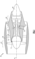
- FIG. 1 schematically illustrates a gas turbine engine 20.
- the example gas turbine engine 20 is a turbofan that generally incorporates a fan section 22, a compressor section 24, a combustor section 26 and a turbine section 28.
- the fan section 22 drives air along a bypass flow path B in a bypass duct defined within a nacelle 30.
- the turbine engine 20 intakes air along a core flow path C into the compressor section 24 for compression and communication into the combustor section 26.
- the compressed air is mixed with fuel from a fuel system 32 and ignited by igniter 34 to generate an exhaust gas flow that expands through the turbine section 28 and is exhausted through exhaust nozzle 36.
- turbofan turbine engine in the disclosed non-limiting embodiment, it should be understood that the concepts described herein are not limited to use with turbofans as the teachings may be applied to other types of turbine engines.
- the propulsor may be an enclosed fan, the propulsor may be an open propeller. This embodiment can also be applied to industrial gas turbine engine as well.
- Figure 2 schematically illustrates a computer 100 modeling a design for a casing 102 which may be an inter compressor case for a gas turbine engine such as that shown in Figure 1 .
- the casing 102 could be in locations other than the compressor, and may be utilized in other type engines.
- the casing 102 is formed of thin sheet metal, and provided with cutouts 104.
- the case is shown to have a relatively large conical portion 106 merging into a relatively smaller diameter cylindrical portion 108.
- Cutout 104 is in conical portion 106.
- An accessory 109 is shown mounted on the case 102.
- the accessory can be any number of components which may be utilized with the gas turbine engine. As examples, the accessory could be sensors, fuel or oil system effectors, tanks, or any number of accessories.
- a location of a peak displacement point 110 is determined by the modeling through known techniques. As shown, peak location 110 is adjacent the cutout 104. Further, other displacement portions 112 and 114 are illustrated. Area 112 may be the peak displacement at that axial position on the case 102. Known modeling techniques may be utilized to develop the location of the peak displacement based upon things such as the expected rotor speeds within the engine, the thickness of the sheet metal, etc.
- FIG 3 shows a casing 202 which may result from the modeling of Figure 2 .
- Casing 202 has a cutout 204.
- An area (110) of concern 210 is shown at an edge 211 of the cutout 204.
- Area of concern 210 may be an area which will potentially be subject to high vibration levels.
- the casing 202 again has a conical portion 206 extending radially inwardly to a cylindrical portion 208.
- area 212 is shown as an area (112) of very high likely vibration, with areas 214 showing circumferentially adjacent which may be also of concern due to vibration levels.
- a stiffening element 220 is put on location 210 to provide local stiffness to the casing. The use of this stiffening element will mistune the casing at that location such that the area 210 should be of less concern.
- the stiffening element 220 illustrated here has a general H-shape with legs 222 connected by a connection 224.
- a H-shaped stiffening element 230 extends across area of concern 212 and adjacent areas 214. Again, there are legs 232 connected by a connector 234.
- an accessory 209 may be on the wall of the casing 202 and may cause some of the vibration concerns at areas 212 and 214.
- Figure 4 shows another embodiment casing 302.
- a cutout 304 has a stiffening element 320 on area 310 adjacent an edge 311.
- Stiffening element 320 is bar shaped and extends between ends 332.
- the casing 302 again has a conical portion 306 extending radially inwardly to a cylindrical portion 308.
- a stiffening element 330 extends across areas 312 and 314.
- Stiffening element 330 is bar shaped and has ends 332 which will end within the areas of concern 314.
- Figure 5 shows a casing embodiment 402 where a stiffening element 430 is placed on an inner peripheral wall of the casing 408.
- stiffening elements 220/230, 320/330 and 430 are all fixed to the casing at least at their ends.
- H and bar shaped stiffening elements are shown they may be any number of other shapes, e.g. T or D shaped, etc.
- Figure 6 shows yet another embodiment where a casing 502 has an area of concern 512.
- a dimple 530 is provided in a wall of the casing to provide the local stiffening element.
- Figure 7 is a flow chart of a method according to this disclosure.
- a casing is modeled to identify peak displacement locations.
- a stiffening element is fixed to a wall of the casing.
- a gas turbine engine under this disclosure could be said to include a compressor section 24, a combustor 26 and a turbine section 28.
- At least one casing 202/302/402/502 surrounds at least one of the compressor and turbine section.
- the at least one casing is formed of sheet metal, and has at least one potential peak displacement point due to vibration across a speed range of the at least one of the compressor and turbine section.
- a stiffening element 220/230/320/330/430/530 is fixed to a wall of the casing at the at least one potential peak displacement point.
- the wall is an outer wall of the casing.
- the wall is an inner wall of the casing.
- At least one accessory 209 mounted to a wall of the casing and impacting on the at least one peak displacement points.
- the at least one stiffening element is H-shaped 220/230.
- the at least one stiffening element 320/330/430 is bar shaped.
- the at least one stiffening element is a dimple 530 formed in the wall.
- the stiffening element is formed of sheet metal.
- a method of providing a casing for a gas turbine engine under this disclosure could be said to include 1) modeling a casing design 600 for a casing to be formed of sheet metal, 2) determining peak displacement locations based upon the modeling of step 1) and 3) providing a stiffening element 602 at at least one of the peak displacement location, the stiffening element fixed to a wall of the casing.
- the wall is an outer wall of the casing.
- the wall is an inner wall of the casing.
- At least one accessory mounted to a wall of the casing and impacting on the at least one peak displacement locations.
- the at least one stiffening element is H-shaped.
- the at least one stiffening element is bar shaped.
- the at least one stiffening element is a dimple formed in the wall.
- the stiffening element is formed of sheet metal.
Landscapes
- Engineering & Computer Science (AREA)
- Mechanical Engineering (AREA)
- General Engineering & Computer Science (AREA)
- Chemical & Material Sciences (AREA)
- Combustion & Propulsion (AREA)
- Structures Of Non-Positive Displacement Pumps (AREA)
Abstract
A gas turbine engine (20) includes a compressor section (24), a combustor (26) and a turbine section (28). At least one casing (202; 302; 402; 502) surrounds at least one of the compressor and turbine sections (24, 28). The at least one casing (202... 502) is formed of sheet metal, and has at least one potential peak displacement point (210; 212; 310; 314; 512) due to vibration across a speed range of the at least one of the compressor and turbine sections (24, 28). A stiffening element (220; 230; 320; 330; 430; 530) is fixed to a wall of the casing at the at least one potential peak displacement point (210...512).
Description
- This application relates to local stiffening to a sheet metal housing for a gas turbine engine to address areas of vibration concern.
- Gas turbines are known, and typically include a propulsor delivering air into a core engine. The core engine may include a compressor section for compressing the air and delivering it into a combustor. The air is mixed with fuel and ignited in the combustor. Products of this combustion pass downstream over turbine rotors driving them to rotate. The turbine rotors in turn drive compressor and propulsor rotors.
- There are several housings in a typical gas turbine engine. One such housing is an inter compressor case. The inter compressor case may be located between a high pressure compressor and a low pressure compressor. Typically the inter compressor case is formed of sheet metal which is welded to form a full hoop structure. To reduce weight there may be several cutouts in the sheet metal wall.
- Further, accessories may be mounted to the inter compressor case.
- In practice, the inter compressor case may have a number of locations that raise vibration concerns at speeds within the engine speed running range. There are many nodal diameter modes that may have modal inferences within the engine speed range. That is, the inter compressor case may get excited to vibrate by the rotation of the rotor(s).
- A gas turbine engine under this disclosure could be said to include a compressor section, a combustor and a turbine section. At least one casing surrounds at least one of the compressor and turbine section. The at least one casing is formed of sheet metal, and has at least one potential peak displacement point due to vibration across a speed range of the at least one of the compressor and turbine section. A stiffening element is fixed to a wall of the casing at the at least one potential peak displacement point.
- A method of providing a casing for a gas turbine engine under this disclosure could be said to include 1) modeling a casing design for a casing to be formed of sheet metal, 2) determining peak displacement locations based upon the modeling of step 1) and 3) providing a stiffening element at at least one of the peak displacement location, the stiffening element fixed to a wall of the casing.
- These and other features will be best understood from the following drawings and specification, the following is a brief description.
-
-
Figure 1 is a schematic view of a gas turbine engine. -
Figure 2 shows a computer modeling of a casing which may be part of theFigure 1 engine. -
Figure 3 shows a casing with local stiffening elements resulting from the modeling ofFigure 2 . -
Figure 4 shows another embodiment casing. -
Figure 5 shows yet another embodiment casing. -
Figure 6 shows yet another embodiment casing. -
Figure 7 is a flow chart of a method. -
Figure 1 schematically illustrates agas turbine engine 20. The examplegas turbine engine 20 is a turbofan that generally incorporates afan section 22, acompressor section 24, acombustor section 26 and aturbine section 28. Thefan section 22 drives air along a bypass flow path B in a bypass duct defined within anacelle 30. Theturbine engine 20 intakes air along a core flow path C into thecompressor section 24 for compression and communication into thecombustor section 26. In thecombustor section 26, the compressed air is mixed with fuel from afuel system 32 and ignited byigniter 34 to generate an exhaust gas flow that expands through theturbine section 28 and is exhausted throughexhaust nozzle 36. Although depicted as a turbofan turbine engine in the disclosed non-limiting embodiment, it should be understood that the concepts described herein are not limited to use with turbofans as the teachings may be applied to other types of turbine engines. As one example, rather than having the propulsor be an enclosed fan, the propulsor may be an open propeller. This embodiment can also be applied to industrial gas turbine engine as well. -
Figure 2 schematically illustrates acomputer 100 modeling a design for acasing 102 which may be an inter compressor case for a gas turbine engine such as that shown inFigure 1 . However, thecasing 102 could be in locations other than the compressor, and may be utilized in other type engines. - The
casing 102 is formed of thin sheet metal, and provided withcutouts 104. The case is shown to have a relatively largeconical portion 106 merging into a relatively smaller diametercylindrical portion 108.Cutout 104 is inconical portion 106. Anaccessory 109 is shown mounted on thecase 102. The accessory can be any number of components which may be utilized with the gas turbine engine. As examples, the accessory could be sensors, fuel or oil system effectors, tanks, or any number of accessories. - A location of a
peak displacement point 110 is determined by the modeling through known techniques. As shown,peak location 110 is adjacent thecutout 104. Further,other displacement portions Area 112 may be the peak displacement at that axial position on thecase 102. Known modeling techniques may be utilized to develop the location of the peak displacement based upon things such as the expected rotor speeds within the engine, the thickness of the sheet metal, etc. -
Figure 3 shows acasing 202 which may result from the modeling ofFigure 2 . Casing 202 has acutout 204. An area (110) ofconcern 210 is shown at anedge 211 of thecutout 204. Area ofconcern 210 may be an area which will potentially be subject to high vibration levels. Thecasing 202 again has aconical portion 206 extending radially inwardly to acylindrical portion 208. - Further,
area 212 is shown as an area (112) of very high likely vibration, withareas 214 showing circumferentially adjacent which may be also of concern due to vibration levels. - A
stiffening element 220 is put onlocation 210 to provide local stiffness to the casing. The use of this stiffening element will mistune the casing at that location such that thearea 210 should be of less concern. Thestiffening element 220 illustrated here has a general H-shape with legs 222 connected by aconnection 224. - Similarly, a H-shaped
stiffening element 230 extends across area ofconcern 212 andadjacent areas 214. Again, there arelegs 232 connected by aconnector 234. - As shown, an
accessory 209 may be on the wall of thecasing 202 and may cause some of the vibration concerns atareas -
Figure 4 shows anotherembodiment casing 302. Here, acutout 304 has astiffening element 320 onarea 310 adjacent anedge 311. Stiffeningelement 320 is bar shaped and extends between ends 332. Thecasing 302 again has aconical portion 306 extending radially inwardly to acylindrical portion 308. Astiffening element 330 extends acrossareas element 330 is bar shaped and has ends 332 which will end within the areas ofconcern 314. -
Figure 5 shows acasing embodiment 402 where astiffening element 430 is placed on an inner peripheral wall of the casing 408. - The stiffening
elements 220/230, 320/330 and 430 are all fixed to the casing at least at their ends. - While H and bar shaped stiffening elements are shown they may be any number of other shapes, e.g. T or D shaped, etc.
-
Figure 6 shows yet another embodiment where acasing 502 has an area ofconcern 512. Adimple 530 is provided in a wall of the casing to provide the local stiffening element. -
Figure 7 is a flow chart of a method according to this disclosure. At step 600 a casing is modeled to identify peak displacement locations. At step 602 a stiffening element is fixed to a wall of the casing. - A gas turbine engine under this disclosure could be said to include a
compressor section 24, acombustor 26 and aturbine section 28. At least onecasing 202/302/402/502 surrounds at least one of the compressor and turbine section. The at least one casing is formed of sheet metal, and has at least one potential peak displacement point due to vibration across a speed range of the at least one of the compressor and turbine section. Astiffening element 220/230/320/330/430/530 is fixed to a wall of the casing at the at least one potential peak displacement point. - In another embodiment according to the previous embodiment, there are a plurality of peak displacement points at distinct locations and a plurality of the stiffening elements.
- In another embodiment according to any of the previous embodiments, the wall is an outer wall of the casing.
- In another embodiment according to any of the previous embodiments, the wall is an inner wall of the casing.
- In another embodiment according to any of the previous embodiments, there is at least one
accessory 209 mounted to a wall of the casing and impacting on the at least one peak displacement points. - In another embodiment according to any of the previous embodiments, there is a
cutout 204/304 through the wall of the casing and the at least one peak displacement point is adjacent one wall of the cutout. - In another embodiment according to any of the previous embodiments, the at least one stiffening element is H-shaped 220/230.
- In another embodiment according to any of the previous embodiments, the at least one
stiffening element 320/330/430 is bar shaped. - In another embodiment according to any of the previous embodiments, the at least one stiffening element is a
dimple 530 formed in the wall. - In another embodiment according to any of the previous embodiments, the stiffening element is formed of sheet metal.
- A method of providing a casing for a gas turbine engine under this disclosure could be said to include 1) modeling a
casing design 600 for a casing to be formed of sheet metal, 2) determining peak displacement locations based upon the modeling of step 1) and 3) providing astiffening element 602 at at least one of the peak displacement location, the stiffening element fixed to a wall of the casing. - In another embodiment according to any of the previous embodiments, there are a plurality of peak displacement points at distinct locations and a plurality of the stiffening elements.
- In another embodiment according to any of the previous embodiments, the wall is an outer wall of the casing.
- In another embodiment according to any of the previous embodiments, the wall is an inner wall of the casing.
- In another embodiment according to any of the previous embodiments, there is at least one accessory mounted to a wall of the casing and impacting on the at least one peak displacement locations.
- In another embodiment according to any of the previous embodiments, there is a cutout through the wall of the casing and the at least one peak displacement point is adjacent one wall of the cutout.
- In another embodiment according to any of the previous embodiments, the at least one stiffening element is H-shaped.
- In another embodiment according to any of the previous embodiments, the at least one stiffening element is bar shaped.
- In another embodiment according to any of the previous embodiments, the at least one stiffening element is a dimple formed in the wall.
- In another embodiment according to any of the previous embodiments, the stiffening element is formed of sheet metal.
- Although embodiments have been disclosed, a worker of skill in this art would recognize that modifications would come within the scope of this disclosure. For that reason, the following claims should be studied to determine the true scope and content.
Claims (15)
- A gas turbine engine (20) comprising:a compressor section (24), a combustor (26) and a turbine section (28);at least one casing (202; 302; 402; 502) surrounding at least one of the compressor section (24) and turbine section (28), the at least one casing (202...502) formed of sheet metal, and the at least one casing (202...502) having at least one potential peak displacement point (210; 212; 310; 314; 512) due to vibration across a speed range of the at least one of the compressor section (24) and turbine section (28); anda stiffening element (220; 230; 320; 330; 430; 530) fixed to a wall of the at least one casing (202...502) at the at least one potential peak displacement point (210...512).
- The gas turbine engine as set forth in claim 1, wherein there are a plurality of peak displacement points (210...512) at distinct locations and a plurality of the stiffening elements (220...530).
- The gas turbine engine as set forth in claim 1 or 2, wherein the wall is an outer wall of the casing (202...502).
- The gas turbine engine as set forth in claim 1 or 2, wherein the wall is an inner wall of the casing (202...502).
- The gas turbine engine as set forth in any preceding claim, wherein there is at least one accessory (209; 309) mounted to a wall of the casing (202...502) and impacting on the at least one peak displacement point (210...512).
- The gas turbine engine as set forth in any preceding claim, wherein there is a cutout (204; 304) through the wall of the casing (202; 302) and the at least one peak displacement point (210; 320) is adjacent one wall of the cutout (204; 304).
- The gas turbine engine as set forth in any preceding claim, wherein the at least one stiffening element (220...430) is H-shaped or bar shaped.
- The gas turbine engine as set forth in any preceding claim, wherein the at least one stiffening element (530) is a dimple formed in the wall or the at least one stiffening element (220...430) is formed of sheet metal.
- A method of providing a casing (202...502) for a gas turbine engine (20) comprising the steps of:1) modeling a casing design for a casing (202... 502) to be formed of sheet metal;2) determining at least one peak displacement point (210...512) based upon the modeling of step 1); and3) providing a stiffening element (220...530) at the at least one peak displacement point (210...512), the stiffening element (220...520) fixed to a wall of the casing (202...502).
- The method as set forth in claim 9, wherein there are a plurality of peak displacement points (210...512) at distinct locations and a plurality of the stiffening elements.
- The method as set forth in claim 9 or 10, wherein the wall is an outer wall of the casing or the wall is an inner wall of the casing.
- The method as set forth in claim 9, 10 or 11, wherein there is at least one accessory (209; 309) mounted to a wall of the casing (202...502) and impacting on the at least one peak displacement point (210...512) .
- The method as set forth in any of claims 9 to 12, wherein there is a cutout (204; 304) through the wall of the casing (202; 302) and the at least one peak displacement point (210; 320) is adjacent one wall of the cutout (204; 304).
- The method as set forth in any of claims 9 to 12, wherein the at least one stiffening element (220...430) is H-shaped or bar shaped.
- The method as set forth in any of claims 9 to 12, wherein the at least one stiffening element (530) is a dimple formed in the wall or the at least one stiffening element (220...430) is formed of sheet metal.
Applications Claiming Priority (1)
| Application Number | Priority Date | Filing Date | Title |
|---|---|---|---|
| US18/348,915 US12158076B1 (en) | 2023-07-07 | 2023-07-07 | Local stiffening for gas turbine engine casing |
Publications (1)
| Publication Number | Publication Date |
|---|---|
| EP4488495A1 true EP4488495A1 (en) | 2025-01-08 |
Family
ID=91853454
Family Applications (1)
| Application Number | Title | Priority Date | Filing Date |
|---|---|---|---|
| EP24186953.6A Pending EP4488495A1 (en) | 2023-07-07 | 2024-07-05 | Local stiffening for gas turbine engine casing |
Country Status (3)
| Country | Link |
|---|---|
| US (2) | US12158076B1 (en) |
| EP (1) | EP4488495A1 (en) |
| CA (1) | CA3246678A1 (en) |
Families Citing this family (1)
| Publication number | Priority date | Publication date | Assignee | Title |
|---|---|---|---|---|
| US12270313B2 (en) | 2023-09-01 | 2025-04-08 | Pratt & Whitney Canada Corp. | Engine carcass stiffener for high maneuver loads |
Citations (4)
| Publication number | Priority date | Publication date | Assignee | Title |
|---|---|---|---|---|
| US20110283711A1 (en) * | 2008-06-17 | 2011-11-24 | Volvo Aero Corporation | Gas turbine component and a gas turbine engine comprising the component |
| US9003852B2 (en) * | 2006-09-29 | 2015-04-14 | Rolls-Royce Plc | Sheet metal blank |
| US20190093514A1 (en) * | 2016-03-31 | 2019-03-28 | Mitsubishi Hitachi Power Systems, Ltd. | Casing position adjustment device |
| US20220082028A1 (en) * | 2020-09-11 | 2022-03-17 | Doosan Heavy Industries & Construction Co., Ltd. | Vibration damper, exhaust diffuser system, and gas turbine including same |
Family Cites Families (26)
| Publication number | Priority date | Publication date | Assignee | Title |
|---|---|---|---|---|
| US3996019A (en) * | 1975-04-18 | 1976-12-07 | General Electric Company | Fabrication method and fabricated article |
| US5483792A (en) * | 1993-05-05 | 1996-01-16 | General Electric Company | Turbine frame stiffening rails |
| US5605438A (en) * | 1995-12-29 | 1997-02-25 | General Electric Co. | Casing distortion control for rotating machinery |
| US6257829B1 (en) * | 2000-02-16 | 2001-07-10 | General Electric Company | Computerized method for positioning support jacks underneath industrial gas turbines |
| EP1783330A3 (en) * | 2003-07-29 | 2011-03-09 | Pratt & Whitney Canada Corp. | Casing of a turbofan engine |
| US7370467B2 (en) | 2003-07-29 | 2008-05-13 | Pratt & Whitney Canada Corp. | Turbofan case and method of making |
| US7594405B2 (en) * | 2006-07-27 | 2009-09-29 | United Technologies Corporation | Catenary mid-turbine frame design |
| SE0700823L (en) * | 2007-03-30 | 2008-10-01 | Volvo Aero Corp | Component for a gas turbine engine, a jet engine equipped with such a component, and an airplane equipped with such a jet engine |
| US8662819B2 (en) * | 2008-12-12 | 2014-03-04 | United Technologies Corporation | Apparatus and method for preventing cracking of turbine engine cases |
| GB201103682D0 (en) * | 2011-03-04 | 2011-04-20 | Rolls Royce Plc | A turbomachine casing assembly |
| US20130022457A1 (en) * | 2011-07-18 | 2013-01-24 | General Electric Company | Multi-shell turbine casing system |
| US9498850B2 (en) * | 2012-03-27 | 2016-11-22 | Pratt & Whitney Canada Corp. | Structural case for aircraft gas turbine engine |
| US9683490B2 (en) * | 2013-11-21 | 2017-06-20 | Rolls-Royce Plc | Pivoting fan track liner for blade retainment |
| GB201320611D0 (en) * | 2013-11-22 | 2014-01-08 | Rolls Royce Plc | Gas turbine engine |
| GB201401767D0 (en) * | 2014-02-03 | 2014-03-19 | Rolls Royce Plc | Gas turbine engine |
| US9347321B2 (en) * | 2014-08-01 | 2016-05-24 | The Boeing Company | Methods for optimized engine balancing based on flight data |
| FR3031469B1 (en) | 2015-01-14 | 2017-09-22 | Snecma | CARRIER IN MATERIAL COMPOSITE WITH ORGANIC MATRIX AUTO-RAIDI |
| US9840937B2 (en) * | 2015-01-14 | 2017-12-12 | Siemens Energy, Inc. | Turbine exhaust cylinder/ turbine exhaust manifold bolted stiffening ribs |
| FR3033839B1 (en) * | 2015-03-16 | 2018-09-28 | Safran Aircraft Engines | AIRCRAFT TURBOMACHINE ASSEMBLY COMPRISING A BLOWER HOUSING EQUIPPED WITH AN ACOUSTIC COATING INTEGRATING A BLOWER HOUSING STIFFENER |
| EP3106686B1 (en) * | 2015-06-15 | 2018-09-12 | Ansaldo Energia IP UK Limited | Damping means for components in a turbomachine and method for assembling said damping means |
| DE102016213810A1 (en) * | 2016-07-27 | 2018-02-01 | MTU Aero Engines AG | Cladding element for a turbine intermediate housing |
| US10808574B2 (en) * | 2016-09-13 | 2020-10-20 | General Electric Company | Turbomachine stator travelling wave inhibitor |
| US10378480B2 (en) * | 2017-02-10 | 2019-08-13 | Rohr, Inc | Blocker door stiffening features |
| US10815804B2 (en) * | 2017-04-04 | 2020-10-27 | General Electric Company | Turbine engine containment assembly and method for manufacturing the same |
| DE102019202072B4 (en) * | 2019-02-15 | 2023-10-26 | Rolls-Royce Deutschland Ltd & Co Kg | Engine assembly with cover part |
| US11261757B2 (en) * | 2019-12-05 | 2022-03-01 | Pratt & Whitney Canada Corp. | Boss for gas turbine engine |
-
2023
- 2023-07-07 US US18/348,915 patent/US12158076B1/en active Active
-
2024
- 2024-07-04 CA CA3246678A patent/CA3246678A1/en active Pending
- 2024-07-05 EP EP24186953.6A patent/EP4488495A1/en active Pending
- 2024-08-09 US US18/799,108 patent/US12448900B2/en active Active
Patent Citations (4)
| Publication number | Priority date | Publication date | Assignee | Title |
|---|---|---|---|---|
| US9003852B2 (en) * | 2006-09-29 | 2015-04-14 | Rolls-Royce Plc | Sheet metal blank |
| US20110283711A1 (en) * | 2008-06-17 | 2011-11-24 | Volvo Aero Corporation | Gas turbine component and a gas turbine engine comprising the component |
| US20190093514A1 (en) * | 2016-03-31 | 2019-03-28 | Mitsubishi Hitachi Power Systems, Ltd. | Casing position adjustment device |
| US20220082028A1 (en) * | 2020-09-11 | 2022-03-17 | Doosan Heavy Industries & Construction Co., Ltd. | Vibration damper, exhaust diffuser system, and gas turbine including same |
Also Published As
| Publication number | Publication date |
|---|---|
| US12448900B2 (en) | 2025-10-21 |
| CA3246678A1 (en) | 2025-06-06 |
| US12158076B1 (en) | 2024-12-03 |
| US20250012204A1 (en) | 2025-01-09 |
Similar Documents
| Publication | Publication Date | Title |
|---|---|---|
| US10240529B2 (en) | Gas turbine engine aft bearing arrangement | |
| EP3464832B1 (en) | Turbine bearing support | |
| US20130195645A1 (en) | Geared turbomachine architecture having a low profile core flow path contour | |
| CN108005786B (en) | Rotor shaft structure for gas turbine engine and method of assembling the same | |
| US10801366B2 (en) | Variable stiffness bearing housing | |
| EP3049655B1 (en) | Gas turbine engine bearing arrangement translating radial vibrations into axial vibrations | |
| EP2984291B1 (en) | Nozzle segment for a gas turbine engine | |
| US12448900B2 (en) | Local stiffening for gas turbine engine casing | |
| US20200173367A1 (en) | Methods and apparatus for controlling at least part of a start-up or re-light process of a gas turbine engine | |
| EP2519721B1 (en) | Damper seal | |
| US20160003093A1 (en) | Fan Axial Containment System | |
| EP3043030B1 (en) | Anti-rotation vane | |
| US12264592B2 (en) | Local vibration damping for gas turbine engine housing | |
| EP2604793A2 (en) | Rotor with Internal Stiffening Ring | |
| EP3052766B1 (en) | Vane seal system and seal therefor | |
| EP3971389A1 (en) | Anti-vortex tube retaining ring and bore basket | |
| EP3760843A1 (en) | Duct assembly for a gas turbine engine | |
| US10533581B2 (en) | Stator with support structure feature for tuned airfoil | |
| US9938854B2 (en) | Gas turbine engine airfoil curvature | |
| US12025053B1 (en) | Cantilever stator vane with damper | |
| US12253009B1 (en) | Instrumented stator with extended internal passages | |
| EP4484704A1 (en) | Mistuning alternate blades in a gas turbine engine | |
| JP2004011458A (en) | Stationary blade clocking device and its position control method | |
| CN117759436A (en) | Muffler components for gas turbine engines | |
| Harper et al. | Design of the 6C Heavy-Duty Gas Turbine |
Legal Events
| Date | Code | Title | Description |
|---|---|---|---|
| PUAI | Public reference made under article 153(3) epc to a published international application that has entered the european phase |
Free format text: ORIGINAL CODE: 0009012 |
|
| STAA | Information on the status of an ep patent application or granted ep patent |
Free format text: STATUS: THE APPLICATION HAS BEEN PUBLISHED |
|
| AK | Designated contracting states |
Kind code of ref document: A1 Designated state(s): AL AT BE BG CH CY CZ DE DK EE ES FI FR GB GR HR HU IE IS IT LI LT LU LV MC ME MK MT NL NO PL PT RO RS SE SI SK SM TR |
|
| STAA | Information on the status of an ep patent application or granted ep patent |
Free format text: STATUS: REQUEST FOR EXAMINATION WAS MADE |
|
| 17P | Request for examination filed |
Effective date: 20250708 |