EP4488491A1 - Pipe assembly - Google Patents
Pipe assembly Download PDFInfo
- Publication number
- EP4488491A1 EP4488491A1 EP24177649.1A EP24177649A EP4488491A1 EP 4488491 A1 EP4488491 A1 EP 4488491A1 EP 24177649 A EP24177649 A EP 24177649A EP 4488491 A1 EP4488491 A1 EP 4488491A1
- Authority
- EP
- European Patent Office
- Prior art keywords
- sealing
- pipe
- pipe assembly
- space
- zone
- Prior art date
- Legal status (The legal status is an assumption and is not a legal conclusion. Google has not performed a legal analysis and makes no representation as to the accuracy of the status listed.)
- Granted
Links
Images


Classifications
-
- F—MECHANICAL ENGINEERING; LIGHTING; HEATING; WEAPONS; BLASTING
- F01—MACHINES OR ENGINES IN GENERAL; ENGINE PLANTS IN GENERAL; STEAM ENGINES
- F01D—NON-POSITIVE DISPLACEMENT MACHINES OR ENGINES, e.g. STEAM TURBINES
- F01D25/00—Component parts, details, or accessories, not provided for in, or of interest apart from, other groups
-
- F—MECHANICAL ENGINEERING; LIGHTING; HEATING; WEAPONS; BLASTING
- F01—MACHINES OR ENGINES IN GENERAL; ENGINE PLANTS IN GENERAL; STEAM ENGINES
- F01D—NON-POSITIVE DISPLACEMENT MACHINES OR ENGINES, e.g. STEAM TURBINES
- F01D9/00—Stators
- F01D9/06—Fluid supply conduits to nozzles or the like
-
- F—MECHANICAL ENGINEERING; LIGHTING; HEATING; WEAPONS; BLASTING
- F02—COMBUSTION ENGINES; HOT-GAS OR COMBUSTION-PRODUCT ENGINE PLANTS
- F02C—GAS-TURBINE PLANTS; AIR INTAKES FOR JET-PROPULSION PLANTS; CONTROLLING FUEL SUPPLY IN AIR-BREATHING JET-PROPULSION PLANTS
- F02C7/00—Features, components parts, details or accessories, not provided for in, or of interest apart form groups F02C1/00 - F02C6/00; Air intakes for jet-propulsion plants
- F02C7/24—Heat or noise insulation
- F02C7/25—Fire protection or prevention
-
- F—MECHANICAL ENGINEERING; LIGHTING; HEATING; WEAPONS; BLASTING
- F16—ENGINEERING ELEMENTS AND UNITS; GENERAL MEASURES FOR PRODUCING AND MAINTAINING EFFECTIVE FUNCTIONING OF MACHINES OR INSTALLATIONS; THERMAL INSULATION IN GENERAL
- F16L—PIPES; JOINTS OR FITTINGS FOR PIPES; SUPPORTS FOR PIPES, CABLES OR PROTECTIVE TUBING; MEANS FOR THERMAL INSULATION IN GENERAL
- F16L57/00—Protection of pipes or objects of similar shape against external or internal damage or wear
- F16L57/04—Protection of pipes or objects of similar shape against external or internal damage or wear against fire or other external sources of extreme heat
-
- F—MECHANICAL ENGINEERING; LIGHTING; HEATING; WEAPONS; BLASTING
- F05—INDEXING SCHEMES RELATING TO ENGINES OR PUMPS IN VARIOUS SUBCLASSES OF CLASSES F01-F04
- F05D—INDEXING SCHEME FOR ASPECTS RELATING TO NON-POSITIVE-DISPLACEMENT MACHINES OR ENGINES, GAS-TURBINES OR JET-PROPULSION PLANTS
- F05D2240/00—Components
- F05D2240/90—Mounting on supporting structures or systems
- F05D2240/91—Mounting on supporting structures or systems on a stationary structure
-
- F—MECHANICAL ENGINEERING; LIGHTING; HEATING; WEAPONS; BLASTING
- F05—INDEXING SCHEMES RELATING TO ENGINES OR PUMPS IN VARIOUS SUBCLASSES OF CLASSES F01-F04
- F05D—INDEXING SCHEME FOR ASPECTS RELATING TO NON-POSITIVE-DISPLACEMENT MACHINES OR ENGINES, GAS-TURBINES OR JET-PROPULSION PLANTS
- F05D2260/00—Function
- F05D2260/50—Kinematic linkage, i.e. transmission of position
-
- F—MECHANICAL ENGINEERING; LIGHTING; HEATING; WEAPONS; BLASTING
- F05—INDEXING SCHEMES RELATING TO ENGINES OR PUMPS IN VARIOUS SUBCLASSES OF CLASSES F01-F04
- F05D—INDEXING SCHEME FOR ASPECTS RELATING TO NON-POSITIVE-DISPLACEMENT MACHINES OR ENGINES, GAS-TURBINES OR JET-PROPULSION PLANTS
- F05D2260/00—Function
- F05D2260/96—Preventing, counteracting or reducing vibration or noise
Definitions
- This disclosure relates to a pipe assembly for a gas turbine engine and a gas turbine engine that includes such a pipe assembly.
- pipes for conducting fluid media have to traverse zones having restrictions due to flammability risks.
- Those different zones within the machine are, e.g., separated by firewalls which have to be traversed by the pipe while allowing for a certain misalignment and having fluid sealing capabilities.
- Fireproof traverses for pipes are known in general from, e.g., United States patent applications US 2022/0055756 A1 and US 2020/0049279 A1 . Those designs do not provide movability in the axial direction of the pipe which is, e.g., required for mechanical movements of the involved parts.
- the present disclosure provides a pipe assembly and a gas turbine engine as set out in the appended claims.
- a pipe assembly for pipe traversing a firewall from a first zone to a second zone in an engine, such as, e.g., an aircraft engine.
- an engine such as, e.g., an aircraft engine.
- zones exist which have to be separated by a material wall, the firewall, to prevent the effects of a fire in one zone, spreading to the other.
- the pipe assembly has to provide some misalignment capability (primarily in axial direction, but to some extent also in radial direction) to adjust for movements of the involved parts.
- a shield device of the pipe assembly provides a spatial separation between a sealing space around the pipe and a part of the first zone.
- the sealing space has an opening towards another part of the first space, i.e., the enclosure by the shield device is not complete.
- a sealing device is movably located within the sealing space through that opening to seal off the sealing space against the first zone. Therefore, the sealing space is closed off against the first zone by the shield device and the sealing device.
- the movability allows, e.g., the axial adjustment to movements, while keeping the separation between the zones on either side of the firewall.
- the shield device and the sealing device are made from a fireproof material, e.g., they are made from a metal or are rubber-free to ensure a fireproof pipe assembly.
- the shield device and the sealing device may be made from the same fireproof material or different fireproof materials.
- At least one part of the shield device is elastically biased against the sealing device, in particular, the at least one sealing element. With this pretension (or bias) in the shield device, the sealing effect can be enhanced.
- the sealing assembly is connected to the firewall so that it will move together with the firewall.
- the sealing space around the pipe is at least in parts convex towards the longitudinal axis of the pipe.
- a convex space is, e.g., a cylindrical space or a cylindrical space with an attached convex space.
- the sealing space comprises at least one section which has a circular, elliptical or polygonal cross-section. Sealing elements can be adapted to those shapes. Furthermore, the sealing space can comprise at least one section which is symmetric to the longitudinal axis of the pipe. One example would be again a cylindrical space or a combined cylindrical-conical space.
- the sealing device comprises at least one sealing element which in operation seals against the inner surface of the shield device.
- the sealing element can, e.g., be made from a metal which is softer than the material of the shield device, against the at least one sealing element is sealing off.
- the sealing element may be a sealing ring.
- the pipe assembly comprises at least one vibration damping device.
- At least one sealing lip can be provided, in particular at the inner wall of the sealing space to protect the sealing sliding components from direct contact with splashing liquid from the outside.
- the shield device is made in one piece with the pipe, e.g. in a casting procedure. It is also possible that the shield device is attached to the pipe, e.g. via connection means (e.g. by welding).
- a gas turbine engine in particular an aircraft engine.
- the gas turbine engine includes at least one pipe assembly of the first aspect.
- FIG. 1 a first embodiment of a pipe assembly 10 is shown in a sectional view.
- a pipe 1 traverses a firewall 20 from a first zone A to a second zone B.
- the firewall 20 separates the zones A, B within a gas turbine engine in an aircraft.
- the embodiment of the pipe assembly 10 is not restricted to this particular application, the fire related regulations in aircraft engines are particularly stringent. This means that, e.g., a fire in the first zone A should not spread into the second zone B or vice versa.
- a fluid such as oil
- a pipe assembly 10 is a pipe 1 connecting different zones within the cowling of an aircraft engine.
- the firewall 20 is made from metal to prevent any burning of the material.
- the firewall 20 furthermore comprises an opening H through which the pipe 1 extends from zone A into zone B. If that opening H is not properly sealed off, hot gases and/or smoke could get into zone B.
- the feedthrough design of the pipe assembly 10 requires some movability, here, in particular, some movability in the direction of the longitudinal axis L of the pipe 1.
- the pipe assembly 10 comprises a shield device 2 which is connected or attached around the pipe 1.
- the shield device 2 is in one piece with the pipe 1.
- the shield device 2 could, e.g., be welded to the pipe 1.
- the shield device 2 circumferentially extends around the pipe 1 and comprises a conical part 2a and a vertical part 2b.
- the conical part 2a is connected or attached to the pipe 1 itself.
- This conical part 2a has an opening angle ⁇ of approximately 140°, around the longitudinal axis L of the pipe 1, as shown in Figure 1 .
- the conical part 2a can have a larger or smaller opening angle, depending on the space available for the pipe assembly 10.
- the vertical part 2b extends downwards.
- the conical space within the conical part 2a is thereby extended by a cylindrical part, i.e., bounded by the vertical part 2b.
- the convex space within the conical part 2a and the vertical part 2b define a sealing space S.
- Embodiments with the shield devices 2 having a different geometry are shown in Figures 2 and 3 .
- the shield device 2 provides a spatial separation between the sealing space S around the pipe 1 and a part of the first zone A.
- the sealing space S comprises an opening O at the rim of the vertical part 2b.
- a sealing device 15, movable in an axial direction is positioned.
- the sealing device 15 is axially movable as indicated by the double arrow.
- the sealing device 15, in this embodiment, is connected with bolts to the firewall 20. So, if the firewall 20 moves, e.g., due to thermal expansion or vibrations, the sealing device can move axially within the sealing space S.
- the sloped outside surface of the conical part 2a effectively guides spray liquids in zone A.
- the sealing device 15 comprises a circumferential sealing element 16 which is made from metal to provide a rubber-free sealing against the inner wall of the vertical part 2b of the sealing device.
- the sealing element 16 can be made from metal that is softer than the metal of the sealing device 2, at least softer than the metal of the vertical part 2b of the sealing device 2.
- sealing spaces S which are convex, making it easier to shape the counterpart, i.e., the sealing device, which is movably located in that convex space.
- a vibration dampening device 3 against vibrations is positioned between the firewall 20 and the sealing device 15.
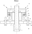
- FIG 2 a variation of the embodiment described in context of Figure 1 is shown so that reference can be made to the above description.
- the difference to the embodiment of Figure 1 is that the shield device 2 does not have a conical part 2a.
- the vertical part 2b of the shield device 2 extends downwards from the circumference of a plate, perpendicular to the longitudinal axis L of the pipe 1. Therefore, the sealing element 16 can travel along the complete sealing space S.
- the vertical part 2b of the shield device is tilted lightly inwards, i.e., towards the longitudinal axis L of the pipe 1.
- the shield device 2 and the matching sealing device 15 the cross-section in a plane perpendicular to the longitudinal axis L of the pipe 2 is circular and symmetrically shaped around the longitudinal axis L. This allows for an efficient circular sealing, as described.
- the cross-sectional shape is non-circular, e.g., it is elliptic or polygonal. This would then define a more complex shaped sealing space S.
- the pipe 1 is assumed to have a circular cross-section. In other embodiments, the pipe 1 could have an elliptic or a polygonal cross-section, so this embodiment could also be called a duct assembly.
Landscapes
- Engineering & Computer Science (AREA)
- General Engineering & Computer Science (AREA)
- Mechanical Engineering (AREA)
- Chemical & Material Sciences (AREA)
- Combustion & Propulsion (AREA)
- Gasket Seals (AREA)
- Support Of The Bearing (AREA)
- Rolling Contact Bearings (AREA)
Abstract
Description
- This disclosure relates to a pipe assembly for a gas turbine engine and a gas turbine engine that includes such a pipe assembly.
- In machines, such as, e.g., gas turbines or aircraft engines, pipes for conducting fluid media have to traverse zones having restrictions due to flammability risks. Those different zones within the machine are, e.g., separated by firewalls which have to be traversed by the pipe while allowing for a certain misalignment and having fluid sealing capabilities.
- Fireproof traverses for pipes are known in general from, e.g.,
United States patent applications US 2022/0055756 A1 andUS 2020/0049279 A1 . Those designs do not provide movability in the axial direction of the pipe which is, e.g., required for mechanical movements of the involved parts. - Therefore, pipe assemblies providing in particular some axial movability are required for a fireproof pipe traverse of a firewall, while retaining sealing capabilities. There is a need to provide a pipe assembly that addresses the aforementioned problems or at least provides a useful alternative to known pipe assemblies.
- The present disclosure provides a pipe assembly and a gas turbine engine as set out in the appended claims.
- In a first aspect there is provided a pipe assembly for pipe traversing a firewall from a first zone to a second zone in an engine, such as, e.g., an aircraft engine. In such engines, zones exist which have to be separated by a material wall, the firewall, to prevent the effects of a fire in one zone, spreading to the other. In addition, the pipe assembly has to provide some misalignment capability (primarily in axial direction, but to some extent also in radial direction) to adjust for movements of the involved parts.
- A shield device of the pipe assembly provides a spatial separation between a sealing space around the pipe and a part of the first zone. The sealing space has an opening towards another part of the first space, i.e., the enclosure by the shield device is not complete.
- A sealing device is movably located within the sealing space through that opening to seal off the sealing space against the first zone. Therefore, the sealing space is closed off against the first zone by the shield device and the sealing device. The movability allows, e.g., the axial adjustment to movements, while keeping the separation between the zones on either side of the firewall.
- The shield device and the sealing device are made from a fireproof material, e.g., they are made from a metal or are rubber-free to ensure a fireproof pipe assembly. The shield device and the sealing device may be made from the same fireproof material or different fireproof materials.
- At least one part of the shield device is elastically biased against the sealing device, in particular, the at least one sealing element. With this pretension (or bias) in the shield device, the sealing effect can be enhanced.
- In some embodiments, the sealing assembly is connected to the firewall so that it will move together with the firewall.
- In some embodiments, the sealing space around the pipe is at least in parts convex towards the longitudinal axis of the pipe. An example for a convex space is, e.g., a cylindrical space or a cylindrical space with an attached convex space.
- For a good sealing effect, the sealing space comprises at least one section which has a circular, elliptical or polygonal cross-section. Sealing elements can be adapted to those shapes. Furthermore, the sealing space can comprise at least one section which is symmetric to the longitudinal axis of the pipe. One example would be again a cylindrical space or a combined cylindrical-conical space.
- In some embodiments, the sealing device comprises at least one sealing element which in operation seals against the inner surface of the shield device. The sealing element can, e.g., be made from a metal which is softer than the material of the shield device, against the at least one sealing element is sealing off. The sealing element may be a sealing ring.
- In some embodiments, the pipe assembly comprises at least one vibration damping device.
- For a further improvement of the sealing, at least one sealing lip can be provided, in particular at the inner wall of the sealing space to protect the sealing sliding components from direct contact with splashing liquid from the outside.
- In some embodiments the shield device is made in one piece with the pipe, e.g. in a casting procedure. It is also possible that the shield device is attached to the pipe, e.g. via connection means (e.g. by welding).
- In a second aspect a gas turbine engine is provided, in particular an aircraft engine. The gas turbine engine includes at least one pipe assembly of the first aspect.
- Embodiments will now be described by way of example only, with reference to the Figures, in which:
-
Figure 1 shows a sectional view of a first embodiment of a pipe assembly; -
Figure 2 shows a sectional view of a second embodiment of a pipe assembly; and -
Figure 3 shows a sectional view of third embodiment of a pipe assembly. - The following table lists the reference numerals used in the drawings with the features to which they refer:
Ref no. Feature Figure 1 Pipe 1 2 3 2 Shield device 1 2 3 2a Conical part of shield device 1 2 3 2b Vertical part of shield device 1 2 3 3 Vibration damping device 1 2 3 10 Pipe assembly 1 2 3 15 Sealing device 1 2 3 16 Sealing element, e.g. sealing ring 1 2 3 17 Sealing lip 1 2 3 20 Firewall 1 2 3 α Opening angle 1 3 A First zone on one side of the wall 1 2 3 B Second zone on the other side of the wall 1 2 3 H Opening in firewall 1 2 3 L Longitudinal axis of the pipe 1 2 3 O Opening of shielding space towards first space 1 2 3 S Sealing space 1 2 3 - Aspects and embodiments of the present disclosure will now be discussed with reference to the accompanying figures. Further aspects and embodiments will be apparent to those skilled in the art.
- In
Figure 1 , a first embodiment of apipe assembly 10 is shown in a sectional view. Apipe 1 traverses afirewall 20 from a first zone A to a second zone B. Thefirewall 20 separates the zones A, B within a gas turbine engine in an aircraft. Even though, the embodiment of thepipe assembly 10 is not restricted to this particular application, the fire related regulations in aircraft engines are particularly stringent. This means that, e.g., a fire in the first zone A should not spread into the second zone B or vice versa. - In the pipe 1 a fluid, such as oil, is flowing, here, from the top in
Figure 1 to the bottom. A typical application of an embodiment of apipe assembly 10 is apipe 1 connecting different zones within the cowling of an aircraft engine. - The
firewall 20 is made from metal to prevent any burning of the material. Thefirewall 20 furthermore comprises an opening H through which thepipe 1 extends from zone A into zone B. If that opening H is not properly sealed off, hot gases and/or smoke could get into zone B. - As small movements of the
pipe 1 and/or thefirewall 20 cannot be prevented, the feedthrough design of thepipe assembly 10 requires some movability, here, in particular, some movability in the direction of the longitudinal axis L of thepipe 1. - In the embodiment shown in
Figure 1 , thepipe assembly 10 comprises ashield device 2 which is connected or attached around thepipe 1. In the embodiment shown, theshield device 2 is in one piece with thepipe 1. In other embodiments, theshield device 2 could, e.g., be welded to thepipe 1. - The
shield device 2 circumferentially extends around thepipe 1 and comprises aconical part 2a and avertical part 2b. Theconical part 2a is connected or attached to thepipe 1 itself. Thisconical part 2a has an opening angle α of approximately 140°, around the longitudinal axis L of thepipe 1, as shown inFigure 1 . In other embodiments, theconical part 2a can have a larger or smaller opening angle, depending on the space available for thepipe assembly 10. - At the distal end of the
conical part 2a, thevertical part 2b extends downwards. The conical space within theconical part 2a is thereby extended by a cylindrical part, i.e., bounded by thevertical part 2b. Together, the convex space within theconical part 2a and thevertical part 2b define a sealing space S. Embodiments with theshield devices 2 having a different geometry are shown inFigures 2 and3 . - The
shield device 2 provides a spatial separation between the sealing space S around thepipe 1 and a part of the first zone A. - The sealing space S comprises an opening O at the rim of the
vertical part 2b. - Into this downward facing opening O (as seen in
Figure 1 ), a sealingdevice 15, movable in an axial direction, is positioned. The sealingdevice 15 is axially movable as indicated by the double arrow. The sealingdevice 15, in this embodiment, is connected with bolts to thefirewall 20. So, if thefirewall 20 moves, e.g., due to thermal expansion or vibrations, the sealing device can move axially within the sealing space S. The sloped outside surface of theconical part 2a effectively guides spray liquids in zone A. - The sealing
device 15 comprises acircumferential sealing element 16 which is made from metal to provide a rubber-free sealing against the inner wall of thevertical part 2b of the sealing device. The sealingelement 16 can be made from metal that is softer than the metal of thesealing device 2, at least softer than the metal of thevertical part 2b of thesealing device 2. - With this
pipe assembly 10, an axial movement of thepipe 1 traversing thefirewall 20 is possible. And - as thepipe 1, theshield device 2 and thefirewall 20 are made from fireproof material (e.g., metal), a robust design is achieved. If there is, e.g., a fire in Zone A, the hot gases and/or smoke cannot enter the zone B because thesealing device 15 with its sealingelement 16 effectively closes off the zone A from zone B. - The embodiments described herein are using sealing spaces S which are convex, making it easier to shape the counterpart, i.e., the sealing device, which is movably located in that convex space.
- As the embodiment of the
pipe assembly 10 comprises moving parts in a dynamic environment, avibration dampening device 3 against vibrations is positioned between thefirewall 20 and the sealingdevice 15. - In
Figure 2 , a variation of the embodiment described in context ofFigure 1 is shown so that reference can be made to the above description. The difference to the embodiment ofFigure 1 is that theshield device 2 does not have aconical part 2a. Thevertical part 2b of theshield device 2, extends downwards from the circumference of a plate, perpendicular to the longitudinal axis L of thepipe 1. Therefore, the sealingelement 16 can travel along the complete sealing space S. - In
Figure 3 , a further variation of the embodiment described in the context ofFigure 1 is shown so that reference can be made to the respective description above. - In this third embodiment, the
vertical part 2b of the shield device is tilted lightly inwards, i.e., towards the longitudinal axis L of thepipe 1. This means that themovable sealing element 16 works against some pretension or bias if it moves axially. This increases the sealing effect, as there is a higher force acting at the sealing than in the case of avertical part 2b without the inward inclination. - In all three embodiments discussed so far, the
shield device 2 and thematching sealing device 15, the cross-section in a plane perpendicular to the longitudinal axis L of thepipe 2 is circular and symmetrically shaped around the longitudinal axis L. This allows for an efficient circular sealing, as described. In other embodiments, the cross-sectional shape is non-circular, e.g., it is elliptic or polygonal. This would then define a more complex shaped sealing space S. - Those shapes might be used in situations where the structural space is less suited for a circular design.
- In the embodiments discussed, the
pipe 1 is assumed to have a circular cross-section. In other embodiments, thepipe 1 could have an elliptic or a polygonal cross-section, so this embodiment could also be called a duct assembly. - It will be understood that the invention is not limited to the embodiments above-described and various modifications and improvements can be made without departing from the concepts described herein. Except where mutually exclusive, any of the features may be employed separately or in combination with any other features and the disclosure extends to and includes all combinations and sub-combinations of one or more features described herein.
Claims (14)
- A pipe assembly (10) for a pipe (1) traversing a firewall (20) from a first zone (A) to a second zone (B) in an engine, the pipe assembly provides a misalignment capability and comprises:a shield device (2) that provides a spatial separation between a sealing space (S) around the pipe (1) and a part of the first zone (A), the sealing space (S) having an opening (O) towards another part of the first space (A); anda sealing device (15) that is movable within the sealing space (S) through the opening (O) to seal off the sealing space (S) against the first zone (A);wherein the shield device (2) and the sealing device (15) are made from a fireproof material; andat least a part of the shield device (1) is elastically biased against the sealing device (15).
- The pipe assembly of claim 1, wherein the sealing assembly (15) is connected to the firewall (20).
- The pipe assembly of claim 1 or 2, wherein the sealing space (S) around the pipe (1) is at least in parts convex towards the longitudinal axis (L) of the pipe (1).
- The pipe assembly of claim 3, wherein the sealing space (S) comprises at least one section which has a circular, elliptical or polygonal cross-section.
- The pipe assembly of claim 3 or 4, wherein the sealing space (S) comprises at least one section which is symmetrical to the longitudinal axis (L) of the pipe (1).
- The pipe assembly of any preceding claim, wherein the sealing device (15) comprises a least one sealing element (16) which in operation seals against an inner surface of the shield device (2).
- The pipe assembly of claim 6, wherein the at least one sealing element (16) is made from a metal that is softer than the material of the shield device (2), against which the at least one sealing device (15) is sealing off.
- The pipe assembly of any preceding claim, wherein at least a part of the shield device (1) is elastically biased against the at least one sealing element (16).
- The pipe assembly of any preceding claim, wherein the pipe assembly includes at least one vibration damping device (3).
- The pipe assembly of any preceding claim, wherein the pipe assembly includes at least one sealing lip (17).
- The pipe assembly of claim 10, wherein the at least one sealing lip (17) is provided at the inner wall of the sealing space (S).
- The pipe assembly of any preceding claim, wherein the shield device (2) is made in one piece with the pipe (1) or is attached to the pipe (1).
- The pipe assembly of any preceding claim, wherein the fireproof material is made from metal or is rubber-free.
- A gas turbine engine that includes at least one pipe assembly (10) of any preceding claim.
Applications Claiming Priority (1)
| Application Number | Priority Date | Filing Date | Title |
|---|---|---|---|
| GBGB2308230.8A GB202308230D0 (en) | 2023-06-02 | 2023-06-02 | Pipe Assembly |
Publications (2)
| Publication Number | Publication Date |
|---|---|
| EP4488491A1 true EP4488491A1 (en) | 2025-01-08 |
| EP4488491B1 EP4488491B1 (en) | 2026-03-04 |
Family
ID=87156966
Family Applications (1)
| Application Number | Title | Priority Date | Filing Date |
|---|---|---|---|
| EP24177649.1A Active EP4488491B1 (en) | 2023-06-02 | 2024-05-23 | Pipe assembly |
Country Status (3)
| Country | Link |
|---|---|
| US (1) | US20240401637A1 (en) |
| EP (1) | EP4488491B1 (en) |
| GB (1) | GB202308230D0 (en) |
Citations (5)
| Publication number | Priority date | Publication date | Assignee | Title |
|---|---|---|---|---|
| EP1987863A1 (en) * | 2007-04-30 | 2008-11-05 | Honeywell International Inc. | Firewall Sealing Assembly |
| EP2896862A1 (en) * | 2014-01-17 | 2015-07-22 | Rolls-Royce plc | Fastener, corresponding assembly and gas turbine |
| US20200049279A1 (en) | 2018-08-07 | 2020-02-13 | General Electric Company | Quick Connect Firewall Seal for Firewall |
| US20220055756A1 (en) | 2020-08-19 | 2022-02-24 | Pratt & Whitney Canada Corp. | Aircraft firewall feedthrough device |
| CN115111063A (en) * | 2021-03-19 | 2022-09-27 | 通用电气公司 | Feedthrough assembly |
-
2023
- 2023-06-02 GB GBGB2308230.8A patent/GB202308230D0/en not_active Ceased
-
2024
- 2024-05-17 US US18/667,598 patent/US20240401637A1/en active Pending
- 2024-05-23 EP EP24177649.1A patent/EP4488491B1/en active Active
Patent Citations (5)
| Publication number | Priority date | Publication date | Assignee | Title |
|---|---|---|---|---|
| EP1987863A1 (en) * | 2007-04-30 | 2008-11-05 | Honeywell International Inc. | Firewall Sealing Assembly |
| EP2896862A1 (en) * | 2014-01-17 | 2015-07-22 | Rolls-Royce plc | Fastener, corresponding assembly and gas turbine |
| US20200049279A1 (en) | 2018-08-07 | 2020-02-13 | General Electric Company | Quick Connect Firewall Seal for Firewall |
| US20220055756A1 (en) | 2020-08-19 | 2022-02-24 | Pratt & Whitney Canada Corp. | Aircraft firewall feedthrough device |
| CN115111063A (en) * | 2021-03-19 | 2022-09-27 | 通用电气公司 | Feedthrough assembly |
Also Published As
| Publication number | Publication date |
|---|---|
| US20240401637A1 (en) | 2024-12-05 |
| GB202308230D0 (en) | 2023-07-19 |
| EP4488491B1 (en) | 2026-03-04 |
Similar Documents
| Publication | Publication Date | Title |
|---|---|---|
| JP5969319B2 (en) | Annular bearing support damper, gas turbine engine including the same, and manufacturing method thereof | |
| US8167494B2 (en) | Squeeze-film damper arrangement | |
| US4660838A (en) | Vibration suppressing sealing device for a rotary machine | |
| KR101076301B1 (en) | Seal ring | |
| US7556295B2 (en) | Axial and radial play and angle compensation of a tolerating pipe connection | |
| JP5779587B2 (en) | Combustion chamber with vented spark plug | |
| GB2102897A (en) | Annular seals | |
| JP6760954B2 (en) | accumulator | |
| JP2016121868A (en) | Compensation assembly for damper of gas turbine | |
| EP4488491B1 (en) | Pipe assembly | |
| KR20140138040A (en) | Damper for gas turbines | |
| US4685703A (en) | Expansible and contractible duct | |
| US5106106A (en) | Sealing structure for use in guiding molten metal from a metallurgical vessel and a seal thereof | |
| US5964250A (en) | Low leakage, articulating fluid transfer tube | |
| EP3315830B1 (en) | Reciprocating cylinder liner seal assembly | |
| US20050035554A1 (en) | Damper device for mechanical seals | |
| US5090198A (en) | Mounting assembly | |
| RU2478535C1 (en) | Carrier rocket tail compartment bottom protection | |
| KR100794845B1 (en) | fitting | |
| US4198064A (en) | Shaft seal | |
| US20220298973A1 (en) | Feed-through assembly | |
| EP3012474A1 (en) | A bearing, a clutch bearing device and a motor vehicle equipped with such a clutch bearing device | |
| JP2009228895A (en) | Bellows device of double structure | |
| KR200221829Y1 (en) | Gas Spring Device | |
| KR102835436B1 (en) | Turbocharger with improved shaft sealing |
Legal Events
| Date | Code | Title | Description |
|---|---|---|---|
| PUAI | Public reference made under article 153(3) epc to a published international application that has entered the european phase |
Free format text: ORIGINAL CODE: 0009012 |
|
| STAA | Information on the status of an ep patent application or granted ep patent |
Free format text: STATUS: THE APPLICATION HAS BEEN PUBLISHED |
|
| AK | Designated contracting states |
Kind code of ref document: A1 Designated state(s): AL AT BE BG CH CY CZ DE DK EE ES FI FR GB GR HR HU IE IS IT LI LT LU LV MC ME MK MT NL NO PL PT RO RS SE SI SK SM TR |
|
| STAA | Information on the status of an ep patent application or granted ep patent |
Free format text: STATUS: REQUEST FOR EXAMINATION WAS MADE |
|
| 17P | Request for examination filed |
Effective date: 20250305 |
|
| GRAP | Despatch of communication of intention to grant a patent |
Free format text: ORIGINAL CODE: EPIDOSNIGR1 |
|
| STAA | Information on the status of an ep patent application or granted ep patent |
Free format text: STATUS: GRANT OF PATENT IS INTENDED |
|
| RIC1 | Information provided on ipc code assigned before grant |
Ipc: F01D 9/06 20060101AFI20250701BHEP Ipc: F01D 25/00 20060101ALI20250701BHEP Ipc: F02C 7/25 20060101ALI20250701BHEP Ipc: F16L 57/04 20060101ALI20250701BHEP |
|
| INTG | Intention to grant announced |
Effective date: 20250731 |
|
| GRAJ | Information related to disapproval of communication of intention to grant by the applicant or resumption of examination proceedings by the epo deleted |
Free format text: ORIGINAL CODE: EPIDOSDIGR1 |
|
| STAA | Information on the status of an ep patent application or granted ep patent |
Free format text: STATUS: REQUEST FOR EXAMINATION WAS MADE |
|
| INTC | Intention to grant announced (deleted) | ||
| GRAS | Grant fee paid |
Free format text: ORIGINAL CODE: EPIDOSNIGR3 |
|
| STAA | Information on the status of an ep patent application or granted ep patent |
Free format text: STATUS: GRANT OF PATENT IS INTENDED |
|
| GRAP | Despatch of communication of intention to grant a patent |
Free format text: ORIGINAL CODE: EPIDOSNIGR1 |
|
| INTG | Intention to grant announced |
Effective date: 20251208 |
|
| GRAA | (expected) grant |
Free format text: ORIGINAL CODE: 0009210 |
|
| STAA | Information on the status of an ep patent application or granted ep patent |
Free format text: STATUS: THE PATENT HAS BEEN GRANTED |
|
| AK | Designated contracting states |
Kind code of ref document: B1 Designated state(s): AL AT BE BG CH CY CZ DE DK EE ES FI FR GB GR HR HU IE IS IT LI LT LU LV MC ME MK MT NL NO PL PT RO RS SE SI SK SM TR |
|
| REG | Reference to a national code |
Ref country code: CH Ref legal event code: F10 Free format text: ST27 STATUS EVENT CODE: U-0-0-F10-F00 (AS PROVIDED BY THE NATIONAL OFFICE) Effective date: 20260304 Ref country code: GB Ref legal event code: FG4D |
|
| P01 | Opt-out of the competence of the unified patent court (upc) registered |
Free format text: CASE NUMBER: UPC_APP_0005810_4488491/2026 Effective date: 20260217 |
|
| REG | Reference to a national code |
Ref country code: IE Ref legal event code: FG4D |
|
| REG | Reference to a national code |
Ref country code: DE Ref legal event code: R096 Ref document number: 602024002937 Country of ref document: DE |