EP4488490A1 - Turbine support case having axial spokes - Google Patents
Turbine support case having axial spokes Download PDFInfo
- Publication number
- EP4488490A1 EP4488490A1 EP24185434.8A EP24185434A EP4488490A1 EP 4488490 A1 EP4488490 A1 EP 4488490A1 EP 24185434 A EP24185434 A EP 24185434A EP 4488490 A1 EP4488490 A1 EP 4488490A1
- Authority
- EP
- European Patent Office
- Prior art keywords
- turbine
- case
- central axis
- spokes
- aircraft engine
- Prior art date
- Legal status (The legal status is an assumption and is not a legal conclusion. Google has not performed a legal analysis and makes no representation as to the accuracy of the status listed.)
- Pending
Links
Images




Classifications
-
- F—MECHANICAL ENGINEERING; LIGHTING; HEATING; WEAPONS; BLASTING
- F01—MACHINES OR ENGINES IN GENERAL; ENGINE PLANTS IN GENERAL; STEAM ENGINES
- F01D—NON-POSITIVE DISPLACEMENT MACHINES OR ENGINES, e.g. STEAM TURBINES
- F01D25/00—Component parts, details, or accessories, not provided for in, or of interest apart from, other groups
- F01D25/16—Arrangement of bearings; Supporting or mounting bearings in casings
- F01D25/162—Bearing supports
-
- F—MECHANICAL ENGINEERING; LIGHTING; HEATING; WEAPONS; BLASTING
- F01—MACHINES OR ENGINES IN GENERAL; ENGINE PLANTS IN GENERAL; STEAM ENGINES
- F01D—NON-POSITIVE DISPLACEMENT MACHINES OR ENGINES, e.g. STEAM TURBINES
- F01D25/00—Component parts, details, or accessories, not provided for in, or of interest apart from, other groups
- F01D25/24—Casings; Casing parts, e.g. diaphragms, casing fastenings
- F01D25/246—Fastening of diaphragms or stator-rings
-
- F—MECHANICAL ENGINEERING; LIGHTING; HEATING; WEAPONS; BLASTING
- F01—MACHINES OR ENGINES IN GENERAL; ENGINE PLANTS IN GENERAL; STEAM ENGINES
- F01D—NON-POSITIVE DISPLACEMENT MACHINES OR ENGINES, e.g. STEAM TURBINES
- F01D25/00—Component parts, details, or accessories, not provided for in, or of interest apart from, other groups
- F01D25/24—Casings; Casing parts, e.g. diaphragms, casing fastenings
- F01D25/243—Flange connections; Bolting arrangements
-
- F—MECHANICAL ENGINEERING; LIGHTING; HEATING; WEAPONS; BLASTING
- F01—MACHINES OR ENGINES IN GENERAL; ENGINE PLANTS IN GENERAL; STEAM ENGINES
- F01D—NON-POSITIVE DISPLACEMENT MACHINES OR ENGINES, e.g. STEAM TURBINES
- F01D9/00—Stators
- F01D9/02—Nozzles; Nozzle boxes; Stator blades; Guide conduits, e.g. individual nozzles
- F01D9/026—Scrolls for radial machines or engines
-
- F—MECHANICAL ENGINEERING; LIGHTING; HEATING; WEAPONS; BLASTING
- F05—INDEXING SCHEMES RELATING TO ENGINES OR PUMPS IN VARIOUS SUBCLASSES OF CLASSES F01-F04
- F05D—INDEXING SCHEME FOR ASPECTS RELATING TO NON-POSITIVE-DISPLACEMENT MACHINES OR ENGINES, GAS-TURBINES OR JET-PROPULSION PLANTS
- F05D2240/00—Components
- F05D2240/10—Stators
- F05D2240/14—Casings or housings protecting or supporting assemblies within
-
- F—MECHANICAL ENGINEERING; LIGHTING; HEATING; WEAPONS; BLASTING
- F05—INDEXING SCHEMES RELATING TO ENGINES OR PUMPS IN VARIOUS SUBCLASSES OF CLASSES F01-F04
- F05D—INDEXING SCHEME FOR ASPECTS RELATING TO NON-POSITIVE-DISPLACEMENT MACHINES OR ENGINES, GAS-TURBINES OR JET-PROPULSION PLANTS
- F05D2260/00—Function
- F05D2260/30—Retaining components in desired mutual position
- F05D2260/31—Retaining bolts or nuts
Definitions
- the invention relates generally to turbomachinery and, more particularly, to a turbine support case for such engines.
- aerodynamic flow distributors such as scroll or volute structures, are used to receive combustion gases and to regulate them in a suitable manner before the combustion gases meet stator vanes or rotor blades of the downstream turbine(s).
- Such structures are subjected to thermal growth, which may have some various effects on surrounding components. Improvements are therefore sought.
- an aircraft engine comprising: a turbine including a turbine rotor rotatable about a central axis; a scroll case having an inlet fluidly connected to a source of combustion gases and an outlet fluidly connected to the turbine, and a conduit extending around the central axis from the inlet to the outlet, the conduit spiraling towards the central axis; a bearing housing extending around the central axis; an exhaust case disposed downstream of the turbine; and a turbine support case secured to the bearing housing and to the exhaust case, the turbine support case having spokes distributed around the central axis and extending along a direction having an axial component relative to the central axis, the spokes extending through the conduit of the scroll case and radially supported by the bearing housing.
- the aircraft engine described above may include any of the following embodiments or features, in any combinations.
- the scroll case includes vanes extending in a direction having an axial component relative to the central axis and across the conduit.
- the spokes are free of connection to the vanes.
- the turbine support case defines a load path from the bearing housing to the exhaust case, the load path independent from the scroll case.
- the scroll case is free from direct connection to the turbine support case.
- annular member is secured to the bearing housing and extending around the central axis, distal ends of the spokes secured to the annular member.
- the annular member includes a peripheral tab extending axially relative to the central axis, the distal ends of the spokes radially supported by the peripheral tab.
- the turbine support case includes a wall extending around the central axis, the spokes protruding from the wall.
- the wall axially overlaps at least a portion of the turbine, the turbine support case having a rear flange secured to a flange of the exhaust case.
- a containment ring is secured to the rear flange of the turbine support case and disposed radially between the wall of the turbine support case and the turbine rotor of the turbine.
- the turbine is an axial turbine having an axial inlet, and wherein the outlet of the scroll case is annular and axially faces the axial inlet of the turbine, the conduit of the scroll case being disposed axially forwardly of the turbine.
- a turbine assembly comprising: a turbine including a turbine rotor rotatable about a central axis; a support structure; a scroll case for receiving combustion gases and for directing the combustion gases to the turbine, the scroll case having a conduit extending around the central axis, the conduit spiraling towards the central axis; and a turbine support case having spokes distributed around the central axis, the spokes extending through the conduit of the scroll case and radially supported by the support structure, wherein a load path extends through the turbine support case independently of the scroll case.
- the turbine assembly described above may include any of the following embodiments or features, in any combinations.
- the scroll case includes vanes extending in a direction having an axial component relative to the central axis across the conduit.
- each of the spokes extends within a respective one of the vanes.
- the spokes are free of connection to the vanes.
- the scroll case is free from direct connection to the turbine support case.
- annular member is secured to the support structure and extending around the central axis, distal ends of the spokes radially secured to the annular member.
- the annular member includes a peripheral flange extending axially relative to the central axis, the distal ends of the spokes radially supported by the peripheral flange.
- the turbine support case includes a wall extending around the central axis, the spokes protruding from the wall.
- the aircraft engine 10 comprises a thermal engine module 11 including one or more internal combustion engine(s), drivingly engaged to a rotatable load 12, herein depicted as a propeller, via an output shaft 13.
- the output shaft 13 may correspond to an engine shaft of the thermal engine module 11.
- the thermal engine module 11 may include any engine having at least one combustion chamber of varying volume.
- the thermal engine module 11 may comprise one or more piston engine(s) or one or more rotary engine(s) (e.g., Wankel engines).
- the aircraft engine 10 further includes a compressor 14 having a compressor inlet receiving ambient air from the environment E outside the aircraft engine 10 and a compressor outlet fluidly connected to an air inlet of the thermal engine module 11.
- the compressor 14 outputs compressed air from the compressor outlet to the thermal engine via a compressed air conduit 16 and a manifold 17.
- the compressed air conduit 16 and the manifold 17 may include any suitable arrangement of pipes configured to distribute compressed air between the different combustion chambers of the thermal engine module 11. Any other suitable configurations used to supply compressed air to the thermal engine module 11 are contemplated without departing from the scope of the present disclosure.
- the aircraft engine 10 further includes a turbine/assembly 15 having an axially facing turbine inlet 15A fluidly connected to an engine outlet of the thermal engine module 11.
- the turbine 15 has a turbine exhaust case 15B via which combustion gases are expelled to the environment E.
- the turbine exhaust case 15B may include a tailpipe or any other suitable structures (e.g., exhaust mixer) for discharging the combustion gases from the aircraft engine 10.
- the turbine 15 includes an axial turbine having successive rows of rotor(s) 15C and stator(s) 15D disposed in alternation along a central axis A of the aircraft engine 10.
- the rotor(s) 15C may include rotor blades mounted to rotor discs.
- the stator(s) 15D may include stator vanes secured at opposite ends to inner and outer shrouds.
- the turbine 15 may include a plurality of stages each including a stator and a rotor.
- the rotors 15C of the turbine 15 are in driving engagement with a turbine shaft 15E.
- the turbine shaft 15E may be drivingly engaged to the output shaft 13, which may correspond to the engine shaft of the thermal engine module 11. Therefore, the turbine 15 may compound power with the thermal engine module 11 to drive the rotatable load 12. In other words, the turbine shaft 15E may be drivingly engaged to the engine shaft of the thermal engine module 11 via suitable gearing. In the embodiment shown, the turbine shaft 15E is drivingly engaged to a compressor shaft of the compressor 14. Thus, the turbine 15 may drive both the rotatable load 12 and the compressor 14.
- the engine shaft of the thermal engine module 11, the output shaft 13, and the turbine shaft 15E are all coaxial about the central axis A. However, in other configurations, the turbine 15 and/or the compressor 14 may have respective shafts radially offset from one another relative to the central axis A.
- the engine outlet of the thermal engine module 11 is fluidly connected to an exhaust manifold 18 that receives combustion gases outputted by the combustion chambers of the thermal engine module 11.
- the exhaust manifold 18 collects the combustion gases from the different combustion chambers and flows these combustion gases to a combustion engine exhaust pipe 19 that feeds the combustion gases to the turbine 15.
- the engine outlet of the thermal engine module 11 is fluidly connected to the turbine inlet 15A via the exhaust manifold 18 and the combustion engine exhaust pipe 19. Any other suitable configurations used to supply combustion gases to the turbine 15 are contemplated without departing from the scope of the present disclosure.
- the combustion gases are flowing within the combustion engine exhaust pipe 19 and reach the turbine 15 in a direction being mainly radial and which may include a circumferential component relative to the central axis A.
- the turbine 15 includes an axial turbine and therefore the turbine inlet 15A receives the combustion gases along a direction being mainly axial relative to the central axis A.
- the aircraft engine 10 further includes a scroll case 20 that regulates and reorients the combustion gases so that they meet an upstream most of the stages of the turbine 15 at the most appropriate angle of attack.
- the flow of combustion gases exiting the scroll case 20 meets a first stage rotor 15C of the turbine 15 before meeting a stator thereof.
- the scroll case 20 may therefore be used to adequately orient the combustion gases at the most appropriate angle to meet the upstream-most airfoils of the turbine 15, which are herein part of one of the first stage rotors 15C.
- the scroll case 20 may be provided in form of a unitary body or mono-case comprising a conduit 21 extending around the central axis A from an inlet 22 to an outlet 23.
- the inlet 22 is fluidly connected to the combustion engine exhaust pipe 19, whereas the outlet 23 is fluidly connected to the turbine inlet 15A ( Fig. 2 ) of the turbine 15.
- the inlet 22 of the conduit 21 has a tangential component and the outlet 23 is an annular outlet facing axially in a rearward direction and in alignment with an annular gas path 15F of the turbine 15.
- Vanes 24 may be provided in the conduit 21 to direct and regulate the flow of combustion gases.
- the vanes 24 may be omitted in some embodiments.
- the conduit 21 of the scroll case 20 is in this embodiment disposed axially forwardly of the turbine 15.
- the conduit 21 comprises a non-axisymmetric portion extending downstream from the inlet 22 and spiraling towards the central axis A. As it progresses circumferentially around the central axis A, the non-axisymmetric portion of the conduit 21 transitions or merges with an axisymmetric portion, which forms a 360 degrees axisymmetric structure around the central axis A.
- the axisymmetric portion extends downstream from the non-axisymmetric portion to the outlet 23.
- the inventors have found that in engine running conditions, the thermal distortions are non-uniform in the non-axisymmetric portion of the scroll case 20. Consequently, using the scroll case 20 to secure the turbine exhaust case 15B may increase tip clearance of the rotors 15C of the turbine 15. In other words, radial thermal growth of the scroll case 20 during use of the engine may move the turbine exhaust case 15B radially outwardly, thus pulling radially on shrouds disposed around the rotors 15C. This may increase tip clearance and, as a result, may impair performance.
- a compressor case 14A of the compressor 14 is radially supported by a bearing housing 30.
- the support structure may be any static component of the engine, such as a support flange and so on.
- Bearings 31 are rollingly engaged to the bearing housing 30 and radially support a shaft of the engine.
- the scroll case 20 is secured to a rear end 32 of the bearing housing 30.
- the scroll case 20 has a radially-inner wall 25 that defines a flange at its rear end. The flange of the radially-inner wall 25 is received within an annular groove defined by the rear end 32 of the bearing housing 30.
- Other configurations are however contemplated. Therefore, the scroll case 20 may not rely on the turbine exhaust case 15B for structural support.
- a turbine support case 40 is used to secure the turbine exhaust case 15B to the compressor case 14A of the compressor 14.
- the turbine support case 40 is independent from the scroll case 20 such that thermal growth of the scroll case 20 may not be transmitted to the turbine exhaust case 15B. Therefore, the turbine exhaust case 15B is secured to the compressor case 14A via the turbine support case 40 independently of the scroll case 20.
- the expression "independent” or “independently” in “independently of the scroll case 20" implies that a load path extends from the compressor case 14A to the turbine exhaust case 15B through the turbine support case 40 without intersecting the scroll case 20. The scroll case 20 is therefore free from intersection to the load path from the compressor case 14A to the turbine exhaust case 15B.
- the scroll case 20 is thus not part of the load path from the compressor case 14A to the turbine exhaust case 15B and loads generated by the turbine 15 on the turbine exhaust case 15B are transmitted to the compressor case 14B via the turbine support case 40 without assistance from the scroll case 20.
- the scroll case 20 is thus outside the load path that extends through the turbine support case 40.
- the scroll case 20 may thus be structurally floating relative to the turbine support case 40.
- the turbine support case 40 has a portion that axially overlaps the scroll case 20 and is secured to an annular member 41, which is itself secured to the bearing housing 30 or any other suitable support structure. More specifically, the annular member 41 has a flange 42 secured (e.g., bolted) to a first flange 33 of the bearing housing 30.
- the bearing housing 30 further has a second flange 34, which may be disposed radially outwardly of the first flange 33 and axially offset from the first flange 33, for being secured (e.g., bolted) to a mating flange of the compressor case 14A.
- the turbine support case 40 includes a wall 43 extending around the central axis A.
- the wall 43 may be cylindrical, frustoconical, or any other suitable shape.
- the wall 43 may extend a full circumference around the central axis A.
- the turbine support case 40 further includes spokes 44 protruding from the wall 43. More specifically, the turbine support case 40 includes an annular axial wall 45 extending radially inwardly from the wall 43.
- the spokes 44 protrude in a direction having an axial component relative to the central axis A from the annular axial wall 45 and away from the wall 43.
- the spokes 44 may be parallel to the central axis A.
- An annular flange 46 is secured to a rear end of the wall 43 and is secured (e.g., bolted) to a mating flange 15G ( Fig. 3 ) of the turbine exhaust case 15B.
- a containment ring 50 may be secured to the flange 15G of the turbine exhaust case 15B via containment ring flange 51, which may be sandwiched between the annular flange 46 of the turbine support case 40 and the flange 15G of the turbine exhaust case 15B.
- the containment ring 50 is, in this embodiment, disposed radially between the wall 43 of the turbine support case 40 and at least one of the rotors 15C of the turbine 15.
- the spokes 44 extend from proximal ends 44A at the annular axial wall 45 to distal ends 44B.
- the distal ends 44B of the spokes 44 are secured to the annular member 41 as will be explained further below.
- the distal ends 44B of the spokes define threaded apertures 44C and pin apertures 44D.
- the threaded apertures 44C may be disposed between two pin apertures 44D, but other configurations are contemplated. For instance, only one or more threaded apertures may be used. Similarly, only one or more pin apertures may be used.
- the pin apertures 44D are sized to receive pins 47 ( Fig.
- fasteners 48 e.g., bolts
- Fig. 4 extend through correspondingly-shaped apertures defined through the annular member 41 and are threadingly engaged to the threaded apertures 44C for securing the spokes 44 to the annular member 41, which is itself secured to the bearing housing 30.
- each of the spokes 44 is received within a respective one of the vanes 24 of the scroll case 20.
- the spokes 44 therefore axially overlap the vanes 24.
- the spokes 44 may be isolated from combustion gases flowing through the scroll case 20 by the vanes 24.
- the spokes 44 may be free of connection to the vanes 24.
- outer surfaces of the spokes 44 may be free of contact with inner surfaces of the vanes 24.
- the vanes 24 may move axially, radially, and/or circumferentially relative to the spokes 44 without transferring any forces to the spokes 44, and vice versa.
- the scroll case 20 is free from direct connection to the turbine support case 40.
- the scroll case 20 is free of contact, attachment, so on with the turbine support case 40.
- the spokes 44 of this embodiment have an elongated, airfoil-like shape to substantially match a shape of the vanes 24.
- the shape of the spokes 44 may be different.
- the spokes 44 may be circular, oval, square, rectangular in cross-section and so on, without departing from the scope of the present disclosure.
- the turbine support case 40 is shown secured to the annular member 41.
- the distal ends 44B of the turbine support case 40 are radially supported by the annular member 41.
- the annular member 41 defines a peripheral tab 49 that protrudes axially relative to a remainder of the annular member 41 and towards the turbine exhaust case 15B.
- the peripheral tab 49 defines a radially-outwardly facing abutment face against which the distal ends 44B of the spokes 44 are supported. Movements of the distal ends 44B of the spokes 44 towards the central axis A are prevented by the peripheral tab 49.
- a spoke interface may be created by a spigot interface machined at the end of the spoke to radially position the structure.
- FIGs. 8-10 another way of securing the turbine support case 40 to the bearing housing is illustrated. For the sake of conciseness, only feature differing from the configuration described above are described below.
- the bearing housing 130 defines bosses 135 that protrude from an annular wall of the bearing housing 130 towards the scroll case 20.
- the distal ends 44B of the spokes 44 are secured to the bosses 135 of the bearing housing 130.
- Each of the distal ends 44B may define an axial abutment with a respective one of the bosses 135.
- the distal ends 44B of the spokes may be secured to the bosses 135 via fasteners received through correspondingly-shaped aperture defined through the bosses 135 and threadingly engaged to the threaded apertures of the distal ends 44B of the spokes 44.
- the disclosed turbine support case may provide a compact design that extends through the housing of the scroll case instead of being cantilevered; it may improve engine efficiency by keeping the tip clearance within a given threshold in operation since radial expansion of the scroll case 20 is not transmitted to the turbine exhaust case 15B, which support shrouds of the rotors; and it may reduce weight.
Landscapes
- Engineering & Computer Science (AREA)
- Mechanical Engineering (AREA)
- General Engineering & Computer Science (AREA)
- Supercharger (AREA)
Abstract
An aircraft engine (10) has: a turbine (15) including a turbine rotor (15C) rotatable about a central axis (A); a scroll case (20) having an inlet (22) fluidly connected to a source of combustion gases and an outlet (23) fluidly connected to the turbine (15), and a conduit (21) extending around the central axis (A) from the inlet (22) to the outlet (23), the conduit (21) spiraling towards the central axis (A); a bearing housing (30) extending around the central axis (A); an exhaust case (15B) disposed downstream of the turbine (15); and a turbine support case (40) secured to the bearing housing (30; 130) and to the exhaust case (15B), the turbine support case (40) having spokes (44) distributed around the central axis (A) and extending along a direction having an axial component relative to the central axis (A), the spokes (44) extending through the conduit (21) of the scroll case (20) and radially supported by the bearing housing (30).
Description
- The invention relates generally to turbomachinery and, more particularly, to a turbine support case for such engines.
- In some engine architectures, aerodynamic flow distributors, such as scroll or volute structures, are used to receive combustion gases and to regulate them in a suitable manner before the combustion gases meet stator vanes or rotor blades of the downstream turbine(s). Such structures are subjected to thermal growth, which may have some various effects on surrounding components. Improvements are therefore sought.
- According to one aspect of the invention, there is provided an aircraft engine, comprising: a turbine including a turbine rotor rotatable about a central axis; a scroll case having an inlet fluidly connected to a source of combustion gases and an outlet fluidly connected to the turbine, and a conduit extending around the central axis from the inlet to the outlet, the conduit spiraling towards the central axis; a bearing housing extending around the central axis; an exhaust case disposed downstream of the turbine; and a turbine support case secured to the bearing housing and to the exhaust case, the turbine support case having spokes distributed around the central axis and extending along a direction having an axial component relative to the central axis, the spokes extending through the conduit of the scroll case and radially supported by the bearing housing.
- The aircraft engine described above may include any of the following embodiments or features, in any combinations.
- In some embodiments, the scroll case includes vanes extending in a direction having an axial component relative to the central axis and across the conduit.
- In some embodiments, each of the spokes extends within a respective one of the vanes.
- In some embodiments, the spokes are free of connection to the vanes.
- In some embodiments, the turbine support case defines a load path from the bearing housing to the exhaust case, the load path independent from the scroll case.
- In some embodiments, the scroll case is free from direct connection to the turbine support case.
- In some embodiments, an annular member is secured to the bearing housing and extending around the central axis, distal ends of the spokes secured to the annular member.
- In some embodiments, the annular member includes a peripheral tab extending axially relative to the central axis, the distal ends of the spokes radially supported by the peripheral tab.
- In some embodiments, the turbine support case includes a wall extending around the central axis, the spokes protruding from the wall.
- In some embodiments, the wall axially overlaps at least a portion of the turbine, the turbine support case having a rear flange secured to a flange of the exhaust case.
- In some embodiments, a containment ring is secured to the rear flange of the turbine support case and disposed radially between the wall of the turbine support case and the turbine rotor of the turbine.
- In some embodiments, the turbine is an axial turbine having an axial inlet, and wherein the outlet of the scroll case is annular and axially faces the axial inlet of the turbine, the conduit of the scroll case being disposed axially forwardly of the turbine.
- According to another aspect of the invention, there is provided a turbine assembly, comprising: a turbine including a turbine rotor rotatable about a central axis; a support structure; a scroll case for receiving combustion gases and for directing the combustion gases to the turbine, the scroll case having a conduit extending around the central axis, the conduit spiraling towards the central axis; and a turbine support case having spokes distributed around the central axis, the spokes extending through the conduit of the scroll case and radially supported by the support structure, wherein a load path extends through the turbine support case independently of the scroll case.
- The turbine assembly described above may include any of the following embodiments or features, in any combinations.
- In some embodiments, the scroll case includes vanes extending in a direction having an axial component relative to the central axis across the conduit.
- In some embodiments, each of the spokes extends within a respective one of the vanes.
- In some embodiments, the spokes are free of connection to the vanes.
- In some embodiments, the scroll case is free from direct connection to the turbine support case.
- In some embodiments, an annular member is secured to the support structure and extending around the central axis, distal ends of the spokes radially secured to the annular member.
- In some embodiments, the annular member includes a peripheral flange extending axially relative to the central axis, the distal ends of the spokes radially supported by the peripheral flange.
- In some embodiments, the turbine support case includes a wall extending around the central axis, the spokes protruding from the wall.
- Reference is now made to the accompanying figures in which:
-
Fig. 1 is a schematic side view of an aircraft engine in accordance with one embodiment; -
Fig. 2 is a side cross-sectional view of a portion of the aircraft engine ofFig. 1 illustrating a hot section of the aircraft engine; -
Fig. 3 is an enlarged view of a portion ofFig. 2 ; -
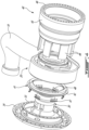
Fig. 4 is a three dimensional exploded view of a turbine assembly for the aircraft engine ofFig. 1 , including a bearing housing, a scroll case, and a turbine support case; -
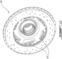
Fig. 5 is a three dimensional view of the turbine support case ofFig. 4 ; -
Fig. 6 is a cross-sectional view taken on a plane normal to a central axis of the aircraft engine ofFig. 1 , illustrating the turbine support case and the scroll case; -
Fig. 7 is a partial three dimensional view of the turbine exhaust case secured to an annular member; -
Fig. 8 is a three dimensional exploded view of a turbine assembly in accordance with another embodiment; -
Fig. 9 is a partial three dimensional view of the turbine assembly ofFig. 8 illustrating the turbine support case and the bearing housing in accordance with another embodiment; and -
Fig. 10 is a front side of the bearing housing ofFig. 8 . - Referring to
Fig. 1 , anaircraft engine 10 is schematically shown. Theaircraft engine 10 comprises athermal engine module 11 including one or more internal combustion engine(s), drivingly engaged to arotatable load 12, herein depicted as a propeller, via an output shaft 13. The output shaft 13 may correspond to an engine shaft of thethermal engine module 11. Thethermal engine module 11 may include any engine having at least one combustion chamber of varying volume. For instance, thethermal engine module 11 may comprise one or more piston engine(s) or one or more rotary engine(s) (e.g., Wankel engines). Theaircraft engine 10 further includes acompressor 14 having a compressor inlet receiving ambient air from the environment E outside theaircraft engine 10 and a compressor outlet fluidly connected to an air inlet of thethermal engine module 11. Thecompressor 14 outputs compressed air from the compressor outlet to the thermal engine via acompressed air conduit 16 and a manifold 17. Thecompressed air conduit 16 and the manifold 17 may include any suitable arrangement of pipes configured to distribute compressed air between the different combustion chambers of thethermal engine module 11. Any other suitable configurations used to supply compressed air to thethermal engine module 11 are contemplated without departing from the scope of the present disclosure. Theaircraft engine 10 further includes a turbine/assembly 15 having an axially facingturbine inlet 15A fluidly connected to an engine outlet of thethermal engine module 11. Theturbine 15 has aturbine exhaust case 15B via which combustion gases are expelled to the environment E. Theturbine exhaust case 15B may include a tailpipe or any other suitable structures (e.g., exhaust mixer) for discharging the combustion gases from theaircraft engine 10. - Referring to
Figs. 1-2 , in one or more embodiment(s), theturbine 15 includes an axial turbine having successive rows of rotor(s) 15C and stator(s) 15D disposed in alternation along a central axis A of theaircraft engine 10. The rotor(s) 15C may include rotor blades mounted to rotor discs. The stator(s) 15D may include stator vanes secured at opposite ends to inner and outer shrouds. In other words, theturbine 15 may include a plurality of stages each including a stator and a rotor. Therotors 15C of theturbine 15 are in driving engagement with aturbine shaft 15E. Theturbine shaft 15E may be drivingly engaged to the output shaft 13, which may correspond to the engine shaft of thethermal engine module 11. Therefore, theturbine 15 may compound power with thethermal engine module 11 to drive therotatable load 12. In other words, theturbine shaft 15E may be drivingly engaged to the engine shaft of thethermal engine module 11 via suitable gearing. In the embodiment shown, theturbine shaft 15E is drivingly engaged to a compressor shaft of thecompressor 14. Thus, theturbine 15 may drive both therotatable load 12 and thecompressor 14. In the exemplified embodiment, the engine shaft of thethermal engine module 11, the output shaft 13, and theturbine shaft 15E are all coaxial about the central axis A. However, in other configurations, theturbine 15 and/or thecompressor 14 may have respective shafts radially offset from one another relative to the central axis A. - As shown in
Fig. 1 , the engine outlet of thethermal engine module 11 is fluidly connected to anexhaust manifold 18 that receives combustion gases outputted by the combustion chambers of thethermal engine module 11. Theexhaust manifold 18 collects the combustion gases from the different combustion chambers and flows these combustion gases to a combustionengine exhaust pipe 19 that feeds the combustion gases to theturbine 15. In other words, the engine outlet of thethermal engine module 11 is fluidly connected to theturbine inlet 15A via theexhaust manifold 18 and the combustionengine exhaust pipe 19. Any other suitable configurations used to supply combustion gases to theturbine 15 are contemplated without departing from the scope of the present disclosure. - As schematically depicted by the flow arrows in
Fig. 1 , the combustion gases are flowing within the combustionengine exhaust pipe 19 and reach theturbine 15 in a direction being mainly radial and which may include a circumferential component relative to the central axis A. However, theturbine 15 includes an axial turbine and therefore theturbine inlet 15A receives the combustion gases along a direction being mainly axial relative to the central axis A. To redirect the combustion gases from a direction being mainly radial to a direction being mainly axial, theaircraft engine 10 further includes ascroll case 20 that regulates and reorients the combustion gases so that they meet an upstream most of the stages of theturbine 15 at the most appropriate angle of attack. In the embodiment shown, the flow of combustion gases exiting thescroll case 20 meets afirst stage rotor 15C of theturbine 15 before meeting a stator thereof. Thescroll case 20 may therefore be used to adequately orient the combustion gases at the most appropriate angle to meet the upstream-most airfoils of theturbine 15, which are herein part of one of thefirst stage rotors 15C. - Referring to
Fig. 3 , as shown in the exemplified embodiment, thescroll case 20 may be provided in form of a unitary body or mono-case comprising aconduit 21 extending around the central axis A from aninlet 22 to anoutlet 23. Theinlet 22 is fluidly connected to the combustionengine exhaust pipe 19, whereas theoutlet 23 is fluidly connected to theturbine inlet 15A (Fig. 2 ) of theturbine 15. According to the illustrated embodiment, theinlet 22 of theconduit 21 has a tangential component and theoutlet 23 is an annular outlet facing axially in a rearward direction and in alignment with anannular gas path 15F of theturbine 15. This configuration allows injecting the combustion gases in a direction being mainly axial relative to the central axis A to meet the axial inlet of theturbine 15.Vanes 24 may be provided in theconduit 21 to direct and regulate the flow of combustion gases. Thevanes 24 may be omitted in some embodiments. Theconduit 21 of thescroll case 20 is in this embodiment disposed axially forwardly of theturbine 15. - The
conduit 21 comprises a non-axisymmetric portion extending downstream from theinlet 22 and spiraling towards the central axis A. As it progresses circumferentially around the central axis A, the non-axisymmetric portion of theconduit 21 transitions or merges with an axisymmetric portion, which forms a 360 degrees axisymmetric structure around the central axis A. The axisymmetric portion extends downstream from the non-axisymmetric portion to theoutlet 23. - The inventors have found that in engine running conditions, the thermal distortions are non-uniform in the non-axisymmetric portion of the
scroll case 20. Consequently, using thescroll case 20 to secure theturbine exhaust case 15B may increase tip clearance of therotors 15C of theturbine 15. In other words, radial thermal growth of thescroll case 20 during use of the engine may move theturbine exhaust case 15B radially outwardly, thus pulling radially on shrouds disposed around therotors 15C. This may increase tip clearance and, as a result, may impair performance. - As illustrated on
Fig. 3 , acompressor case 14A of thecompressor 14 is radially supported by a bearinghousing 30. It will be appreciated that that any suitable support structure may be used for support thecompressor case 14A. For instance, the support structure may be any static component of the engine, such as a support flange and so on.Bearings 31 are rollingly engaged to the bearinghousing 30 and radially support a shaft of the engine. Thescroll case 20 is secured to arear end 32 of the bearinghousing 30. In the exemplified embodiment, thescroll case 20 has a radially-inner wall 25 that defines a flange at its rear end. The flange of the radially-inner wall 25 is received within an annular groove defined by therear end 32 of the bearinghousing 30. Other configurations are however contemplated. Therefore, thescroll case 20 may not rely on theturbine exhaust case 15B for structural support. - In the disclosed embodiment, a
turbine support case 40 is used to secure theturbine exhaust case 15B to thecompressor case 14A of thecompressor 14. As will be explained below, theturbine support case 40 is independent from thescroll case 20 such that thermal growth of thescroll case 20 may not be transmitted to theturbine exhaust case 15B. Therefore, theturbine exhaust case 15B is secured to thecompressor case 14A via theturbine support case 40 independently of thescroll case 20. In the present disclosure, the expression "independent" or "independently" in "independently of thescroll case 20" implies that a load path extends from thecompressor case 14A to theturbine exhaust case 15B through theturbine support case 40 without intersecting thescroll case 20. Thescroll case 20 is therefore free from intersection to the load path from thecompressor case 14A to theturbine exhaust case 15B. Thescroll case 20 is thus not part of the load path from thecompressor case 14A to theturbine exhaust case 15B and loads generated by theturbine 15 on theturbine exhaust case 15B are transmitted to the compressor case 14B via theturbine support case 40 without assistance from thescroll case 20. Thescroll case 20 is thus outside the load path that extends through theturbine support case 40. Thescroll case 20 may thus be structurally floating relative to theturbine support case 40. - Referring to
Fig. 4 , theturbine support case 40 has a portion that axially overlaps thescroll case 20 and is secured to anannular member 41, which is itself secured to the bearinghousing 30 or any other suitable support structure. More specifically, theannular member 41 has aflange 42 secured (e.g., bolted) to afirst flange 33 of the bearinghousing 30. The bearinghousing 30 further has asecond flange 34, which may be disposed radially outwardly of thefirst flange 33 and axially offset from thefirst flange 33, for being secured (e.g., bolted) to a mating flange of thecompressor case 14A. - Referring to
Figs. 4-5 , theturbine support case 40 includes awall 43 extending around the central axis A. Thewall 43 may be cylindrical, frustoconical, or any other suitable shape. Thewall 43 may extend a full circumference around the central axis A. Theturbine support case 40 further includesspokes 44 protruding from thewall 43. More specifically, theturbine support case 40 includes an annularaxial wall 45 extending radially inwardly from thewall 43. Thespokes 44 protrude in a direction having an axial component relative to the central axis A from the annularaxial wall 45 and away from thewall 43. Thespokes 44 may be parallel to the central axis A. Anannular flange 46 is secured to a rear end of thewall 43 and is secured (e.g., bolted) to amating flange 15G (Fig. 3 ) of theturbine exhaust case 15B. - As shown in
Fig. 3 , thewall 43 axially overlaps at least a portion of theturbine 15. Acontainment ring 50 may be secured to theflange 15G of theturbine exhaust case 15B viacontainment ring flange 51, which may be sandwiched between theannular flange 46 of theturbine support case 40 and theflange 15G of theturbine exhaust case 15B. Thecontainment ring 50 is, in this embodiment, disposed radially between thewall 43 of theturbine support case 40 and at least one of therotors 15C of theturbine 15. - As shown in
Fig. 5 , thespokes 44, six in this embodiment, but more or less may be used, extend fromproximal ends 44A at the annularaxial wall 45 to distal ends 44B. The distal ends 44B of thespokes 44 are secured to theannular member 41 as will be explained further below. The distal ends 44B of the spokes define threadedapertures 44C andpin apertures 44D. The threadedapertures 44C may be disposed between twopin apertures 44D, but other configurations are contemplated. For instance, only one or more threaded apertures may be used. Similarly, only one or more pin apertures may be used. Thepin apertures 44D are sized to receive pins 47 (Fig. 4 ) that extend through correspondingly-shaped apertures defined through theannular member 41 and used for locating theannular member 41 to theturbine support case 40. Then, fasteners 48 (e.g., bolts) (Fig. 4 ) extend through correspondingly-shaped apertures defined through theannular member 41 and are threadingly engaged to the threadedapertures 44C for securing thespokes 44 to theannular member 41, which is itself secured to the bearinghousing 30. - Referring to
Figs. 4 and6 , in the embodiment shown, each of thespokes 44 is received within a respective one of thevanes 24 of thescroll case 20. Thespokes 44 therefore axially overlap thevanes 24. Thus, thespokes 44 may be isolated from combustion gases flowing through thescroll case 20 by thevanes 24. Thespokes 44 may be free of connection to thevanes 24. In other words, outer surfaces of thespokes 44 may be free of contact with inner surfaces of thevanes 24. Thevanes 24 may move axially, radially, and/or circumferentially relative to thespokes 44 without transferring any forces to thespokes 44, and vice versa. Put differently, thescroll case 20 is free from direct connection to theturbine support case 40. In other words, thescroll case 20 is free of contact, attachment, so on with theturbine support case 40. Thespokes 44 of this embodiment have an elongated, airfoil-like shape to substantially match a shape of thevanes 24. However, the shape of thespokes 44 may be different. Thespokes 44 may be circular, oval, square, rectangular in cross-section and so on, without departing from the scope of the present disclosure. - Referring now to
Fig. 7 , theturbine support case 40 is shown secured to theannular member 41. The distal ends 44B of theturbine support case 40 are radially supported by theannular member 41. More specifically, theannular member 41 defines aperipheral tab 49 that protrudes axially relative to a remainder of theannular member 41 and towards theturbine exhaust case 15B. Theperipheral tab 49 defines a radially-outwardly facing abutment face against which the distal ends 44B of thespokes 44 are supported. Movements of the distal ends 44B of thespokes 44 towards the central axis A are prevented by theperipheral tab 49. Said differently, a spoke interface may be created by a spigot interface machined at the end of the spoke to radially position the structure. - Referring now to
Figs. 8-10 , another way of securing theturbine support case 40 to the bearing housing is illustrated. For the sake of conciseness, only feature differing from the configuration described above are described below. - In the exemplified embodiment, the bearing
housing 130 definesbosses 135 that protrude from an annular wall of the bearinghousing 130 towards thescroll case 20. The distal ends 44B of thespokes 44 are secured to thebosses 135 of the bearinghousing 130. Each of the distal ends 44B may define an axial abutment with a respective one of thebosses 135. Then, as shown inFig. 10 , the distal ends 44B of the spokes may be secured to thebosses 135 via fasteners received through correspondingly-shaped aperture defined through thebosses 135 and threadingly engaged to the threaded apertures of the distal ends 44B of thespokes 44. - The disclosed turbine support case may provide a compact design that extends through the housing of the scroll case instead of being cantilevered; it may improve engine efficiency by keeping the tip clearance within a given threshold in operation since radial expansion of the
scroll case 20 is not transmitted to theturbine exhaust case 15B, which support shrouds of the rotors; and it may reduce weight. - The embodiments described in this document provide non-limiting examples of possible implementations of the present technology. Upon review of the present disclosure, a person of ordinary skill in the art will recognize that changes may be made to the embodiments described herein without departing from the scope of the present technology. Yet further modifications could be implemented by a person of ordinary skill in the art in view of the present disclosure, which modifications would be within the scope of the present technology.
Claims (13)
- An aircraft engine (10), comprising: a turbine (15) including a turbine rotor (15C) rotatable about a central axis (A); a scroll case (20) having an inlet (22) fluidly connected to a source of combustion gases and an outlet (23) fluidly connected to the turbine (15), and a conduit (21) extending around the central axis (A) from the inlet (22) to the outlet (23), the conduit (21) spiraling towards the central axis (A);a bearing housing (30; 130) extending around the central axis (A);an exhaust case (15B) disposed downstream of the turbine (15); anda turbine support case (40) secured to the bearing housing (30; 130) and to the exhaust case (15B), the turbine support case (40) having spokes (44) distributed around the central axis (A) and extending along a direction having an axial component relative to the central axis (A), the spokes (44) extending through the conduit (21) of the scroll case (20) and radially supported by the bearing housing (30; 130).
- The aircraft engine (10) of claim 1, wherein the scroll case (20) includes vanes (24) extending in a direction having an axial component relative to the central axis (A) and across the conduit (21).
- The aircraft engine (10) of claim 2, wherein each of the spokes (44) extends within a respective one of the vanes (24).
- The aircraft engine (10) of claim 2 or 3, wherein the spokes (44) are free of connection to the vanes (24).
- The aircraft engine (10) of any preceding claim, wherein the turbine support case (40) defines a load path from the bearing housing (30; 130) to the exhaust case (15B), and the load path is independent from the scroll case (20).
- The aircraft engine (10) of any preceding claim, wherein the scroll case (20) is free from direct connection to the turbine support case (40).
- The aircraft engine (10) of any preceding claim, comprising an annular member (41) secured to the bearing housing (30; 130) and extending around the central axis (A), wherein distal ends (44B) of the spokes (44) are secured to the annular member (41).
- The aircraft engine (10) of claim 7, wherein the annular member (41) includes a peripheral tab (49) extending axially relative to the central axis (A), and the distal ends (44B) of the spokes (44) are radially supported by the peripheral tab (49).
- The aircraft engine (10) of any preceding claim, wherein the turbine support case (40) includes a wall (43) extending around the central axis (A), the spokes (44) protruding from the wall (43).
- The aircraft engine (10) of claim 9, wherein the wall (43) axially overlaps at least a portion of the turbine (15), and the turbine support case (40) have a rear flange (46) secured to a flange (15G) of the exhaust case (15B).
- The aircraft engine (10) of claim 10, comprising a containment ring (50) secured to the rear flange (46) of the turbine support case (40) and disposed radially between the wall (43) of the turbine support case (40) and the turbine rotor (15C) of the turbine (15).
- The aircraft engine (10) of any preceding claim, wherein the turbine (15) is an axial turbine having an axial inlet (15A), the outlet (23) of the scroll case (20) is annular and axially faces the axial inlet (15A) of the turbine (15), and the conduit (21) of the scroll case (20) is disposed axially forwardly of the turbine (15).
- The aircraft engine (10) of any preceding claim, wherein a load path extends through the turbine support case (40) independently of the scroll case (20).
Applications Claiming Priority (1)
| Application Number | Priority Date | Filing Date | Title |
|---|---|---|---|
| US18/344,054 US12264595B2 (en) | 2023-06-29 | 2023-06-29 | Turbine support case having axial spokes |
Publications (1)
| Publication Number | Publication Date |
|---|---|
| EP4488490A1 true EP4488490A1 (en) | 2025-01-08 |
Family
ID=91738647
Family Applications (1)
| Application Number | Title | Priority Date | Filing Date |
|---|---|---|---|
| EP24185434.8A Pending EP4488490A1 (en) | 2023-06-29 | 2024-06-28 | Turbine support case having axial spokes |
Country Status (3)
| Country | Link |
|---|---|
| US (1) | US12264595B2 (en) |
| EP (1) | EP4488490A1 (en) |
| CA (1) | CA3239962A1 (en) |
Cited By (6)
| Publication number | Priority date | Publication date | Assignee | Title |
|---|---|---|---|---|
| EP4722498A1 (en) * | 2024-10-01 | 2026-04-08 | Pratt & Whitney Canada Corp. | Turbine support case with axial spokes and retaining members |
| EP4726180A1 (en) * | 2024-10-10 | 2026-04-15 | Pratt & Whitney Canada Corp. | Turbine support case supported by stopping ribs |
| EP4726178A1 (en) * | 2024-10-10 | 2026-04-15 | Pratt & Whitney Canada Corp. | Turbine support case with axial spokes and heat shields |
| EP4726179A1 (en) * | 2024-10-10 | 2026-04-15 | Pratt & Whitney Canada Corp. | Turbine support case with axial spokes and brackets |
| EP4741635A1 (en) * | 2024-11-11 | 2026-05-13 | Pratt & Whitney Canada Corp. | Aircraft engine including diffuser secured to a bearing housing |
| EP4741634A1 (en) * | 2024-11-08 | 2026-05-13 | Pratt & Whitney Canada Corp. | Aircraft propulsion system with turbocompressor unit |
Families Citing this family (2)
| Publication number | Priority date | Publication date | Assignee | Title |
|---|---|---|---|---|
| US12698727B1 (en) * | 2025-06-27 | 2026-08-04 | Pratt & Whitney Canada Corp. | Aircraft engine having scroll case assembly |
| US12704080B1 (en) | 2025-08-19 | 2026-08-11 | Pratt & Whitney Canada Corp. | Hot gas intake scroll case assembly for aircraft engine |
Citations (3)
| Publication number | Priority date | Publication date | Assignee | Title |
|---|---|---|---|---|
| US10030581B2 (en) * | 2016-02-24 | 2018-07-24 | Pratt & Whitney Canada Corp. | Air intake with scroll portion and strutted portion for gas turbine engine |
| EP3199767B1 (en) * | 2016-01-29 | 2019-03-27 | Pratt & Whitney Canada Corp. | Engine assembly with turbine support casing |
| EP4382726A1 (en) * | 2022-12-01 | 2024-06-12 | Pratt & Whitney Canada Corp. | Aircraft engine with exhaust having removable deflector |
Family Cites Families (37)
| Publication number | Priority date | Publication date | Assignee | Title |
|---|---|---|---|---|
| US2421833A (en) | 1943-05-11 | 1947-06-10 | United Aircraft Corp | Turbine construction |
| US3738105A (en) | 1971-06-24 | 1973-06-12 | Avco Corp | Gas turbine engine structure |
| CH610987A5 (en) * | 1975-08-29 | 1979-05-15 | Bbc Brown Boveri & Cie | |
| US5156534A (en) | 1990-09-04 | 1992-10-20 | United Technologies Corporation | Rotary machine having back to back turbines |
| US5105625A (en) | 1990-11-23 | 1992-04-21 | General Motors Corporation | Mounting for a ceramic scroll in a gas turbine machine |
| DE19524731A1 (en) * | 1995-07-07 | 1997-01-09 | Bmw Rolls Royce Gmbh | Turboprop engine with an air-oil cooler |
| JP3757999B2 (en) | 1996-08-28 | 2006-03-22 | 石川島播磨重工業株式会社 | Scroll seal structure in gas turbine |
| JP2002349276A (en) | 2001-05-25 | 2002-12-04 | Aisin Takaoka Ltd | Turbine housing |
| US6968697B2 (en) * | 2003-09-17 | 2005-11-29 | Honeywell International Inc. | Integral compressor housing of gas turbine engines |
| US7093448B2 (en) | 2003-10-08 | 2006-08-22 | Honeywell International, Inc. | Multi-action on multi-surface seal with turbine scroll retention method in gas turbine engine |
| JP4370232B2 (en) | 2004-09-27 | 2009-11-25 | 三菱重工業株式会社 | Fluid machine with fluid seal mechanism |
| US7731426B2 (en) * | 2007-04-27 | 2010-06-08 | Honeywell International Inc. | Rotor supports and systems |
| FR2919347B1 (en) * | 2007-07-26 | 2009-11-20 | Snecma | EXTERNAL ENVELOPE FOR BLOWER DRIVE IN A TURBOMACHINE. |
| US7931437B1 (en) | 2007-09-21 | 2011-04-26 | Florida Turbine Technologies, Inc. | Turbine case with inlet and outlet volutes |
| KR101200627B1 (en) | 2008-10-20 | 2012-11-12 | 미츠비시 쥬고교 가부시키가이샤 | Radial turbine scroll structure |
| EP2218918A1 (en) | 2009-02-13 | 2010-08-18 | Siemens Aktiengesellschaft | Axial turbo compressor for a gas turbine with low blade-tip leakage losses and diffuser losses |
| JP5769407B2 (en) | 2010-02-01 | 2015-08-26 | 三菱重工業株式会社 | Sheet metal turbine housing |
| DE102010022218A1 (en) | 2010-05-21 | 2011-11-24 | Benteler Automobiltechnik Gmbh | turbocharger |
| US9512721B2 (en) * | 2012-07-20 | 2016-12-06 | Pratt & Whitney Canada Corp. | Compound cycle engine |
| US9194232B2 (en) * | 2012-07-20 | 2015-11-24 | Pratt & Whitney Canada Corp. | Compound cycle engine |
| US9982561B2 (en) | 2012-12-29 | 2018-05-29 | United Technologies Corporation | Heat shield for cooling a strut |
| GB201311072D0 (en) * | 2013-06-21 | 2013-08-07 | Rolls Royce Deutschland & Co Kg | An accessory mounting for a gas turbine engine |
| DE102014012123A1 (en) | 2014-08-14 | 2016-02-18 | Man Diesel & Turbo Se | turbocharger |
| WO2016071959A1 (en) | 2014-11-04 | 2016-05-12 | 三菱重工業株式会社 | Turbine housing and method for manufacturing turbine housing |
| US9896998B2 (en) * | 2015-02-20 | 2018-02-20 | Pratt & Whitney Canada Corp. | Compound engine assembly with modulated flow |
| WO2016159004A1 (en) | 2015-03-31 | 2016-10-06 | 株式会社Ihi | Variable displacement supercharger |
| DE102015006460A1 (en) | 2015-05-20 | 2015-12-03 | Daimler Ag | Radial compressor, in particular for an exhaust gas turbocharger of an internal combustion engine |
| DE102015006457A1 (en) | 2015-05-20 | 2015-12-03 | Daimler Ag | Radial compressor, in particular for an exhaust gas turbocharger of an internal combustion engine |
| US10494955B2 (en) | 2017-01-30 | 2019-12-03 | Garrett Transportation I Inc. | Sheet metal turbine housing with containment dampers |
| WO2018179328A1 (en) | 2017-03-31 | 2018-10-04 | 三菱重工エンジン&ターボチャージャ株式会社 | Turbine housing and turbo charger provided with same |
| CN111033012B (en) | 2017-08-28 | 2021-12-28 | 株式会社丰田自动织机 | Turbocharger |
| JP6933257B2 (en) | 2017-08-28 | 2021-09-08 | 株式会社豊田自動織機 | Turbocharger |
| US10815832B2 (en) | 2018-06-19 | 2020-10-27 | Raytheon Technologies Corporation | Load transfer in turbine exhaust case |
| US11187149B2 (en) | 2019-11-25 | 2021-11-30 | Transportation Ip Holdings, Llc | Case-integrated turbomachine wheel containment |
| US11643218B2 (en) | 2021-08-05 | 2023-05-09 | Pratt & Whitney Canada Corp. | AFT engine mount ring with spigot |
| US11821361B1 (en) * | 2022-07-06 | 2023-11-21 | Pratt & Whitney Canada Corp. | Gas turbine intake for aircraft engine and method of inspection thereof |
| US12065950B1 (en) * | 2023-04-06 | 2024-08-20 | Pratt & Whitney Canada Corp. | Structural scroll case |
-
2023
- 2023-06-29 US US18/344,054 patent/US12264595B2/en active Active
-
2024
- 2024-05-29 CA CA3239962A patent/CA3239962A1/en active Pending
- 2024-06-28 EP EP24185434.8A patent/EP4488490A1/en active Pending
Patent Citations (3)
| Publication number | Priority date | Publication date | Assignee | Title |
|---|---|---|---|---|
| EP3199767B1 (en) * | 2016-01-29 | 2019-03-27 | Pratt & Whitney Canada Corp. | Engine assembly with turbine support casing |
| US10030581B2 (en) * | 2016-02-24 | 2018-07-24 | Pratt & Whitney Canada Corp. | Air intake with scroll portion and strutted portion for gas turbine engine |
| EP4382726A1 (en) * | 2022-12-01 | 2024-06-12 | Pratt & Whitney Canada Corp. | Aircraft engine with exhaust having removable deflector |
Cited By (6)
| Publication number | Priority date | Publication date | Assignee | Title |
|---|---|---|---|---|
| EP4722498A1 (en) * | 2024-10-01 | 2026-04-08 | Pratt & Whitney Canada Corp. | Turbine support case with axial spokes and retaining members |
| EP4726180A1 (en) * | 2024-10-10 | 2026-04-15 | Pratt & Whitney Canada Corp. | Turbine support case supported by stopping ribs |
| EP4726178A1 (en) * | 2024-10-10 | 2026-04-15 | Pratt & Whitney Canada Corp. | Turbine support case with axial spokes and heat shields |
| EP4726179A1 (en) * | 2024-10-10 | 2026-04-15 | Pratt & Whitney Canada Corp. | Turbine support case with axial spokes and brackets |
| EP4741634A1 (en) * | 2024-11-08 | 2026-05-13 | Pratt & Whitney Canada Corp. | Aircraft propulsion system with turbocompressor unit |
| EP4741635A1 (en) * | 2024-11-11 | 2026-05-13 | Pratt & Whitney Canada Corp. | Aircraft engine including diffuser secured to a bearing housing |
Also Published As
| Publication number | Publication date |
|---|---|
| US12264595B2 (en) | 2025-04-01 |
| US20250003354A1 (en) | 2025-01-02 |
| CA3239962A1 (en) | 2025-10-31 |
Similar Documents
| Publication | Publication Date | Title |
|---|---|---|
| US12264595B2 (en) | Turbine support case having axial spokes | |
| EP4446570A1 (en) | Structural scroll case | |
| EP2230386B1 (en) | Compressor diffuser | |
| CN118647801A (en) | Turbine assembly including a half-shell housing carrying variable pitch inlet stator blades | |
| US20120272663A1 (en) | Centrifugal compressor assembly with stator vane row | |
| EP1952029B1 (en) | Inlet duct for rearward-facing compressor wheel, and turbocharger incorporating same | |
| KR20140099206A (en) | Axial turbine with meridionally divided turbine housing | |
| US12404777B1 (en) | Turbine support case with axial spokes and retaining members | |
| CN108799200A (en) | Compressor unit with discharge groove and auxiliary flange | |
| CA2957457A1 (en) | Doubler attachment system | |
| EP4726178A1 (en) | Turbine support case with axial spokes and heat shields | |
| CN115413308B (en) | Compressor module for a turbomachine | |
| US12529325B1 (en) | Turbine exhaust duct with stiffeners for aircraft engines | |
| EP4325059A1 (en) | Compressor having a dual-impeller | |
| CN121195107A (en) | Recycled Circulating Aircraft Turbine Engine | |
| US11578654B2 (en) | Centrifical compressor assembly for a gas turbine engine | |
| CN111594279A (en) | Turbine with alternately spaced rotor blades | |
| US2722802A (en) | Axial flow turbojet engines having independently rotating low and high pressure systems | |
| US12486788B1 (en) | Turbine support case supported by stopping ribs | |
| US12467473B1 (en) | Aircraft engine including diffuser secured to a bearing housing | |
| CA3203404A1 (en) | Gas turbine intake for aircraft engine and method of inspection thereof | |
| US12595750B1 (en) | Turbine support case with axial spokes and brackets | |
| US12565847B1 (en) | Aircraft engine having a scroll case and a turbine support case secured together | |
| EP4733547A1 (en) | Aircraft engine having scroll case with flange connection | |
| EP4311943B1 (en) | Diffuser and associated compressor section of aircraft engine |
Legal Events
| Date | Code | Title | Description |
|---|---|---|---|
| PUAI | Public reference made under article 153(3) epc to a published international application that has entered the european phase |
Free format text: ORIGINAL CODE: 0009012 |
|
| STAA | Information on the status of an ep patent application or granted ep patent |
Free format text: STATUS: THE APPLICATION HAS BEEN PUBLISHED |
|
| AK | Designated contracting states |
Kind code of ref document: A1 Designated state(s): AL AT BE BG CH CY CZ DE DK EE ES FI FR GB GR HR HU IE IS IT LI LT LU LV MC ME MK MT NL NO PL PT RO RS SE SI SK SM TR |
|
| STAA | Information on the status of an ep patent application or granted ep patent |
Free format text: STATUS: REQUEST FOR EXAMINATION WAS MADE |
|
| 17P | Request for examination filed |
Effective date: 20250708 |