EP4488341A1 - Radiation-curable ink composition, method for preparing the same and method for applying an image onto a recording medium - Google Patents
Radiation-curable ink composition, method for preparing the same and method for applying an image onto a recording medium Download PDFInfo
- Publication number
- EP4488341A1 EP4488341A1 EP24185071.8A EP24185071A EP4488341A1 EP 4488341 A1 EP4488341 A1 EP 4488341A1 EP 24185071 A EP24185071 A EP 24185071A EP 4488341 A1 EP4488341 A1 EP 4488341A1
- Authority
- EP
- European Patent Office
- Prior art keywords
- radiation
- ink composition
- curable
- curable ink
- recording medium
- Prior art date
- Legal status (The legal status is an assumption and is not a legal conclusion. Google has not performed a legal analysis and makes no representation as to the accuracy of the status listed.)
- Pending
Links
Images

Classifications
-
- C—CHEMISTRY; METALLURGY
- C09—DYES; PAINTS; POLISHES; NATURAL RESINS; ADHESIVES; COMPOSITIONS NOT OTHERWISE PROVIDED FOR; APPLICATIONS OF MATERIALS NOT OTHERWISE PROVIDED FOR
- C09D—COATING COMPOSITIONS, e.g. PAINTS, VARNISHES OR LACQUERS; FILLING PASTES; CHEMICAL PAINT OR INK REMOVERS; INKS; CORRECTING FLUIDS; WOODSTAINS; PASTES OR SOLIDS FOR COLOURING OR PRINTING; USE OF MATERIALS THEREFOR
- C09D11/00—Inks
- C09D11/02—Printing inks
- C09D11/10—Printing inks based on artificial resins
- C09D11/101—Inks specially adapted for printing processes involving curing by wave energy or particle radiation, e.g. with UV-curing following the printing
-
- C—CHEMISTRY; METALLURGY
- C09—DYES; PAINTS; POLISHES; NATURAL RESINS; ADHESIVES; COMPOSITIONS NOT OTHERWISE PROVIDED FOR; APPLICATIONS OF MATERIALS NOT OTHERWISE PROVIDED FOR
- C09D—COATING COMPOSITIONS, e.g. PAINTS, VARNISHES OR LACQUERS; FILLING PASTES; CHEMICAL PAINT OR INK REMOVERS; INKS; CORRECTING FLUIDS; WOODSTAINS; PASTES OR SOLIDS FOR COLOURING OR PRINTING; USE OF MATERIALS THEREFOR
- C09D11/00—Inks
- C09D11/30—Inkjet printing inks
- C09D11/38—Inkjet printing inks characterised by non-macromolecular additives other than solvents, pigments or dyes
-
- B—PERFORMING OPERATIONS; TRANSPORTING
- B41—PRINTING; LINING MACHINES; TYPEWRITERS; STAMPS
- B41J—TYPEWRITERS; SELECTIVE PRINTING MECHANISMS, i.e. MECHANISMS PRINTING OTHERWISE THAN FROM A FORME; CORRECTION OF TYPOGRAPHICAL ERRORS
- B41J11/00—Devices or arrangements of selective printing mechanisms, e.g. ink-jet printers or thermal printers, for supporting or handling copy material in sheet or web form
- B41J11/0015—Devices or arrangements of selective printing mechanisms, e.g. ink-jet printers or thermal printers, for supporting or handling copy material in sheet or web form for treating before, during or after printing or for uniform coating or laminating the copy material before or after printing
- B41J11/002—Curing or drying the ink on the copy materials, e.g. by heating or irradiating
- B41J11/0021—Curing or drying the ink on the copy materials, e.g. by heating or irradiating using irradiation
- B41J11/00214—Curing or drying the ink on the copy materials, e.g. by heating or irradiating using irradiation using UV radiation
-
- C—CHEMISTRY; METALLURGY
- C09—DYES; PAINTS; POLISHES; NATURAL RESINS; ADHESIVES; COMPOSITIONS NOT OTHERWISE PROVIDED FOR; APPLICATIONS OF MATERIALS NOT OTHERWISE PROVIDED FOR
- C09D—COATING COMPOSITIONS, e.g. PAINTS, VARNISHES OR LACQUERS; FILLING PASTES; CHEMICAL PAINT OR INK REMOVERS; INKS; CORRECTING FLUIDS; WOODSTAINS; PASTES OR SOLIDS FOR COLOURING OR PRINTING; USE OF MATERIALS THEREFOR
- C09D11/00—Inks
- C09D11/02—Printing inks
- C09D11/12—Printing inks based on waxes or bitumen
-
- C—CHEMISTRY; METALLURGY
- C09—DYES; PAINTS; POLISHES; NATURAL RESINS; ADHESIVES; COMPOSITIONS NOT OTHERWISE PROVIDED FOR; APPLICATIONS OF MATERIALS NOT OTHERWISE PROVIDED FOR
- C09D—COATING COMPOSITIONS, e.g. PAINTS, VARNISHES OR LACQUERS; FILLING PASTES; CHEMICAL PAINT OR INK REMOVERS; INKS; CORRECTING FLUIDS; WOODSTAINS; PASTES OR SOLIDS FOR COLOURING OR PRINTING; USE OF MATERIALS THEREFOR
- C09D11/00—Inks
- C09D11/30—Inkjet printing inks
- C09D11/34—Hot-melt inks
-
- C—CHEMISTRY; METALLURGY
- C09—DYES; PAINTS; POLISHES; NATURAL RESINS; ADHESIVES; COMPOSITIONS NOT OTHERWISE PROVIDED FOR; APPLICATIONS OF MATERIALS NOT OTHERWISE PROVIDED FOR
- C09D—COATING COMPOSITIONS, e.g. PAINTS, VARNISHES OR LACQUERS; FILLING PASTES; CHEMICAL PAINT OR INK REMOVERS; INKS; CORRECTING FLUIDS; WOODSTAINS; PASTES OR SOLIDS FOR COLOURING OR PRINTING; USE OF MATERIALS THEREFOR
- C09D11/00—Inks
- C09D11/30—Inkjet printing inks
- C09D11/32—Inkjet printing inks characterised by colouring agents
Definitions
- the present invention relates to a radiation-curable ink composition.
- the present invention further relates to a method for preparing a radiation-curable ink composition.
- the present invention relates to a method for applying an image onto a recording medium.
- Radiation-curable ink compositions are known in the art. These ink compositions comprise one or more radiation curable components.
- a special class of radiation curable ink compositions are radiation curable gel ink compositions. These inks are fluid at elevated temperature and become solid -even if not yet cured- at lower temperatures. These inks are typically jetted at elevated temperatures. Gel inks may become solid or semi-solid upon cooling down on a recording medium, e.g. a sheet of paper. As a result, spread of a droplet of ink on the recording medium may be decreased and color bleeding may be prevented.
- Radiation curable gel ink compositions typically comprise a gelling agent.
- the gelling agent provides the ink composition with gelling property.
- the gelling process is a complex process.
- the gelling process may influence the microstructure of the ink layer, which may influence the appearance of the ink layer.
- the gloss level of the ink layer may be influenced by the gelling process.
- Suitably controlling the gelling process is difficult, especially in cases wherein the temperature of the recording medium during the printing process is not controlled. The temperature of the recording medium may change and consequently, the gloss level of prints made may change. This is unwanted.
- the object of the invention is achieved in a radiation-curable ink composition, wherein the radiation-curable ink composition comprises at least one radiation-curable component and a gelling agent, the at least one radiation-curable component being present in an amount of 55 wt% or more, based on the total weight of the radiation-curable ink composition, wherein the radiation-curable ink composition further comprises a polyalkylene wax, wherein the polyalkylene wax has a molecular weight of 1000 g/mole or less.
- the radiation curable inkjet ink composition may comprise at least one radiation curable component.
- a radiation-curable component is a component that may react (e.g. polymerize) under influence of suitable radiation, such as electromagnetic radiation, e.g. ultraviolet (UV) radiation.
- suitable radiation such as electromagnetic radiation, e.g. ultraviolet (UV) radiation.
- the at least one radiation-curable component may comprise radiation-curable monomers and/or radiation-curable oligomers.
- the monomers and oligomers may be monofunctional (i.e. one polymerizable group per molecule), difunctional (i.e. two polymerizable groups per molecule), trifunctional (i.e. three polymerizable groups per molecule), tetrafunctional ( i.e. four polymerizable groups per molecule), or multifunctional (i.e. five or more polymerizable groups per molecule).
- radiation-curable monomers are (meth)acrylates, epoxides, vinyls, vinylethers, vinyl esters, vinylether acrylates, allyl ethers, allyl esters, acrylamides, methacrylamides, styrenes, maleates, fumarates and itaconates.
- radiation-curable oligomers examples include urethane acrylate oligomers, polyester oligomers, amine functionalized oligomers, polyether oligomers, polyamide oligomers, acrylate oligomers and epoxy based materials such as bisphenol A epoxy acrylates and epoxy acrylates.
- the one or more radiation-curable components may comprise one or more acrylates.
- the one or more radiation-curable components may comprise a monofunctional components and a non-monofunctional component, such as a difunctional, trifunctional, tetrafunctional and polyfunctional component.
- the radiation-curable matrix may comprise at least one amine acrylate.
- Amine acrylates are also known as acrylated amines. Amine acrylates may improve the surface curing of the ink layer upon exposure to radiation, such as UV radiation.
- the ink composition may comprise one type of radiation curable compound or alternatively, the radiation curable medium may comprise a mixture of radiation curable compounds.
- the at least one radiation-curable component may be present in an amount of at least 55 wt%, based on the total weight of the radiation-curable ink composition.
- the at least one radiation-curable component may be present in an amount of at least 60 wt%, based on the total weight of the radiation-curable ink composition, such as an amount of at least 65 wt%, based on the total weight of the radiation-curable ink composition, for example an amount of at least 70 wt%, based on the total weight of the radiation-curable ink composition.
- the at least one radiation-curable component may be present in an amount of 95 wt% or less, based on the total weight of the radiation-curable ink composition. More preferably, the at least one radiation-curable component may be present in an amount of 90 wt% or less, based on the total weight of the radiation-curable ink composition.
- the radiation-curable component may be present in an amount of at least 55 wt%, based on the total weight of the radiation-curable ink composition.
- the radiation-curable ink composition comprises a plurality of radiation-curable components
- the total amount of the plurality of radiation-curable components may be at least 55 wt%, based on the total weight of the radiation-curable ink composition.
- the radiation-curable ink composition comprises less than 55wt% of the at least one radiation-curable component, the robustness of the image formed after printing and curing may be insufficient.
- the ink further comprises a gelling agent.
- Gelling agents are also known in the art as gellants or thickeners. The presence of a gelling agent can cause a viscosity increase in the inkjet ink composition upon cooling of the ink composition. The viscosity increase in the ink composition should be sufficient, to adequately control droplet spreading.
- Examples of gellants used in gelling radiation curable inkjet ink compositions are waxes, such as paraffin wax, microcrystalline wax, polyethylene waxes, polypropylene waxes, and natural waxes, such as animal-based waxes or plant-based waxes, fatty acids, fatty alcohols, ketones, fatty acid esters and fatty acid amides.
- Polylakylene waxes are a class of waxes based on alkylene polymers or alkylene copolymers.
- alkylene polymers are polyethylene and polypropylene.
- Ethylene-propylene copolymers are an example of alkylene copolymers.
- the polywax according to the present invention has a molecular weight of 1000 g/mole or less.
- the molecular weight of the polyalkylene wax may be the number average molecular weight (M n ) of the polyalkylene wax.
- polyalkylene waxes having a molecular weight of 1000 g/mole or less include, but are not limited to Polywax (R) 1000, Polywax (R) 850, Polywax (R) 725, Polywax (R) 655 , Polywax (R) 600, Polywax (R) 500 and Polywax (R) 400.
- an ink composition comprising a gelling agent as well as a polyalkylene wax having a molecular weight of 1000 g/mole or less, results in prints having a higher gloss level.
- the polyalkylene wax is a linear poly-alkylene wax.
- the polyalkylene wax is a polyethylene wax.
- the polyalkylene wax is a linear polyethylene wax.
- the radiation curable inkjet ink composition may further comprise a colorant, such as a pigment, a dye or a mixture thereof. Further, the radiation curable inkjet ink composition may comprise a mixture of dyes and/or a mixture of pigments.
- the colorant may provide the ink composition with a predetermined color. The colorant may be a cyan, magenta, black, yellow, brown orange, green, blue, red, purple or white colorant.
- the radiation curable medium may optionally comprise at least one inhibitor.
- An inhibitor is a component that prevent (inhibits) unwanted polymerization of the radiation curable compound.
- Inhibitors may be added to the radiation curable inkjet ink composition to increase the shelf life on the ink composition.
- the radiation curable medium may optionally comprise at least one photo initiator.
- a photo initiator is a component that improves the efficiency of curing; i.e. increases the polymerization rate when the ink composition is irradiated with suitable radiation, such as UV radiation.
- the radiation curable medium may optionally comprise a solvent, such as water or an organic solvent.
- the solvent may be added to the radiation curable medium to tune ink properties, such as viscosity.
- the radiation curable medium may comprise surfactants, antibacterial components and anti-fungi components.
- the gelling agent is a fatty acid ester.
- Fatty acids are suitable for forming esters, when reacted with a compound comprising an hydroxyl functional group.
- the fatty acids may be saturated or non-saturated fatty acids.
- Non-saturated fatty acids may be monounsaturated fatty acids or polyunsaturated fatty acids.
- Non-saturated fatty acids comprise an alkene functional group.
- the alkene functional group may react and the ester compound may be incorporated in the network formed by the radiation-curable component.
- the fatty acid is a saturated fatty acid.
- the compound B is a fatty acid, no so-called blooming of the ink may occur.
- Blooming is an unwanted phenomena that may occur in ink composition, such as radiation-curable ink composition comprising a gelling agent.
- a gelling agent present in the ink may cool down and may solidify, thereby forming a three-dimensional network that increases the viscosity of the ink.
- the gelling agent may migrate to the surface of the ink layer, which may result in matt print appearance.
- the phenomenon of decreased gloss due to migration of the gelling agent is known as "blooming".
- the gellant is an ester obtainable by a condensation reaction between a fatty acid and a component selected from the group consisting of pentaerythritol, cyclodextrine, glycerol, dipentaerythritol, 2-(hydroxymethyl)-2-methylpropane-1,3-diol, 2-ethyl-2-(hydroxymethyl)propane-1,3-diol, 2-(hydroxymethyl)propane-1,3-diol, trimethylolethane, trimethylolpropane, trimethylolbutane and trimethylolpentane.
- a component selected from the group consisting of pentaerythritol, cyclodextrine, glycerol, dipentaerythritol, 2-(hydroxymethyl)-2-methylpropane-1,3-diol, 2-ethyl-2-(hydroxymethyl)propane-1,3-diol, 2-(hydroxymethyl)propane-1,
- the gelling agent is a fatty acid ester of pentaerythritol.
- Fatty acid esters of pentaerythritol may be suitably used as gelling agent for a radiation-curable ink composition.
- fatty acid esters of pentaerythritol include pentaerythritoltetralaurate, pentaerythritoltetramyristate, pentaerythritoltetrapalmitate, pentaerythritoltetrastearate, pentaerythritoltetra-arachidate, pentaerythritoltetrabehenate, pentaerythritoltetralignocerate and pentaerythritoltetracerotate.
- the gelling agent is present in an amount of from 0.1 wt% to 15 wt% based on the total weight of the radiation-curable ink composition.
- the gelling agent may be present in an amount of from 0.2 wt% to 10 wt% based on the total weight of the ink composition, more preferably from 0.4 wt% to 5 wt% based on the total weight of the ink composition.
- the radiation-curable ink composition may not undergo a phase change upon application onto a recording medium.
- the amount of gellant is more than 15 wt%, based on the total weight of the radiation-curable ink composition, then the radiation-curable ink composition may be difficult to jet using an inkjet print head
- the polyalkylene wax is present in an amount of from 0.01 wt% to 5 wt% based on the total amount of the radiation-curable ink composition.
- the polyalkylene wax is present in an amount of from 0. 1 wt% to 2 wt% based on the total amount of the radiation-curable ink composition.
- a method for preparing a radiation-curable ink composition comprising the steps of:
- the method may result in the preparation of the radiation-curable ink composition according to the present invention.
- a method for applying an image onto a recording medium comprising the steps of:
- an image is applied to the recording medium.
- the image may be applied using an ink composition according to the present invention.
- the ink composition may be applied onto the recording medium in a predetermined fashion, e.g. in accordance with image files stored on suitable storing means.
- the image may be applied for example by jetting droplets of the radiation-curable inkjet ink composition using an inkjet print head.
- the recording medium may be a sheet-like medium, such as a sheet of paper or a sheet of vinyl.
- the recording medium may be a web, for example an endless belt.
- the web may be made of a suitable material.
- the image may be dried after it has been applied onto the intermediate transfer member.
- the radiation-curable inkjet ink composition is cured by irradiating the ink composition using UV radiation.
- the inkjet ink composition may be irradiated using a suitable source of radiation, such as a halogen lamp, a mercury lamp and/or a LED lamp.
- a suitable source of radiation such as a halogen lamp, a mercury lamp and/or a LED lamp.
- a plurality of sources of radiation may be used to irradiate the inkjet ink composition.
- a time interval between jetting droplets of the radiation-curable ink composition and curing the radiation-curable ink composition is at least 30 seconds.
- the time interval between applying the radiation-curable ink and curing the radiation-curable ink may be at least 30 seconds, preferably at least 60 seconds.
- an image may be formed comprising a plurality of layers, without intermediate curing of the ink.
- the time interval between applying the ink and curing the ink is at least 30 seconds, the ink may spread sufficiently, resulting in good image quality.
- Fig. 1 shows a printing apparatus.
- a printing apparatus is also known as printer.
- the printing apparatus 1 comprises an scanning printing unit 7 for printing on a recording medium 15.
- the recording medium 15 in Fig. 1 is a relatively rigid substrate, such as a panel.
- the recording medium 15 is supplied from a media input unit 14, which may be configured for storing a plurality of such print media 15 and supplying these to the printer 1.
- the printer 1 comprises a medium support 4.
- Printer 1 may further comprise transport means for receiving and transporting the recording medium 15 along the scanning printing unit 7.
- the medium support is embodied as an endless belt 4.
- the endless belt is an endless transport belt 4 supported on a plurality of support rollers 3A, 3B, 3C.
- At least one of the support rollers 3A, 3B, 3C is provided with driving means for moving the belt 4.
- the belt 4 is therefore configured to support and transport the recording medium. Additionally, one or more one of the support rollers 3A, 3B, 3C may be configured to be moved and/or tilted to adjust and control the lateral position of the belt 4.
- the scanning printing unit 7 may be provided with a sensor 8, such as a CCD camera, to determine the relative position of belt 4 and/or the recording medium 15. Data from said sensor 8 may be applied to control the position of the belt 4 and/or the recording medium 15.
- the belt 4 is further provided with through-holes and a suction box 5 in connection with a suction source (not shown), such that an underpressure may be applied to the recording medium 15 via the through-holes in the belt 4.
- the underpressure adheres the recording medium 15 flatly to the belt 4 and prevents displacement of the recording medium 15 with respect to the belt 4. Due to this holding the belt 4 is able to transport the recording medium 15. It will be appreciated that other suitable transport means, such as rollers, steppers, etc, may alternatively be applied.
- the recording medium 15 may be transported stepwise and/or in continuous movement.
- the scanning printing unit 7 is configured to translate along a first guide beam 6 in a scanning direction. The scanning direction is perpendicular to the direction in which the print medium is transported by the belt 4.
- the scanning printing unit 7 holds a plurality of print heads (not shown), which are configured to jet a plurality of different marking materials (different colors of ink, primers, coatings, etc.) on the recording medium 15.
- Each marking material for use in the scanning printing unit 7 is stored in one of a plurality of containers arranged in fluid connection with the respective print heads for supplying marking material to said print heads to print an image on the recording medium 15.
- the application of the marking material, such as the radiation-curable ink from the printing units is performed in accordance with data provided in the respective print job.
- the printing unit may comprise one or more inkjet print heads.
- the timing by which the droplets of marking material are released from the one or more print heads determines their position on the recording medium 15.
- the timing may be adjusted based on the position of the scanning printing unit 7 along the first guide beam 6.
- the above mentioned sensor 8 may therein be applied to determine the relative position and/or velocity of the scanning printing unit 7 with respect to the recording medium 15. Based upon data from the sensor 8, the release timing of the marking material may be adjusted.
- marking material may be spilled and stay on a nozzle surface of the print heads.
- the marking material present on the nozzle surface may negatively influence the ejection of droplets and the placement of these droplets on the recording medium 15. Therefore, it may be advantageous to remove excess of marking material from the nozzle surface.
- the excess of marking material may be removed for example by wiping with a wiper and/or by application of a suitable anti-wetting property of the surface, e.g. provided by a coating.
- the marking materials may require treatment to properly fixate them on the print medium.
- a fixation unit is provided downstream of the scanning printing unit 7.
- the fixation unit may emit radiation to facilitate the marking material fixation process.
- the fixation unit is page-wide curing array 10.
- the page-wide curing array 10 extends in the main scanning direction.
- the page-wide curing array does not move in operation in the main scanning direction.
- the page-wide array may move in the direction of medium transport, which is a direction perpendicular to the scanning direction.
- the fixation unit may be a scanning fixation unit, that in operation moves in reciprocation in the scanning direction.
- the page-wide curing array 10 is configured to in operation emit radiation of certain frequencies, which interacts with the marking materials, for example UV light in case of UV-curable inks.
- the scanning printing unit 7 may be provided with a further fixation unit on the same carriage which holds the print heads. This further fixation unit can be used to (partially) cure and/or harden the marking materials, independent of or interaction with the page-wide curing array 10.
- the recording medium 15 is transported to a receiving unit (not shown).
- the receiving unit may comprise a take-up roller for winding up the recording medium 15, a receiving tray for supporting sheets of recording medium 15, or a rigid media handler, similar to the media input unit 14.
- the receiving unit may comprise processing means for processing the medium 8, 9 after printing, e.g. a post-treatment device such as a coater, a folder, a cutter, or a puncher.
- Printing apparatus 1 furthermore comprises a user interface 11 for receiving print jobs and optionally for manipulating print jobs.
- the local user interface unit 11 is integrated to the print engine and may comprise a display unit and a control panel. Alternatively, the control panel may be integrated in the display unit, for example in the form of a touch-screen control panel.
- the local user interface unit 11 is connected to a control unit 12 connected to the printer 1.
- the control unit 12, for example a computer comprises a processor adapted to issue commands to the printer 1, for example for controlling the print process.
- the printer 1 may optionally be connected to a network. The connection to the network can be via cable or wireless.
- the printer 1 may receive printing jobs via the network.
- the control unit 12 of the printer 1 may be provided with an input port, such as a USB port, so printing jobs may be sent to the printer 1 via this input port.
- the printer 1 in Fig. 1 is a so-called hybrid printer, capable of handling both flexible media and rigid substrates.
- the printer 1 operates in a first print mode, wherein the printer 1 is configured for transporting rigid substrates, such as the recording medium 15.
- rigid print media 15 may be panels, for example panels for doors or walls, corrugated media, plates formed of plastic or metal, etc.
- the printer 1 in Fig. 1 is configured with a substantially linear transport path: from the media input device 14, the recording medium 15 moves forward along the scanning printing unit 7 at a at substantially constant height.
- the media input unit 14 and the receiving unit are positioned at the level of the medium support surface of the belt 4.
- a flexible web medium 16 is supplied to the printer 1, which web medium 16 may be composed of e.g. paper, label stock, coated paper, plastic or textile.
- the web medium 16 is supplied from the input roller 2A and extends across the belt 4 to the take-up roller 2B, where the web medium 16 is re-wound.
- the printer 1 is configured to swiftly and efficiently switch between print modes.
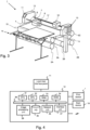
- Figure 3 shows a printer similar to the printer shown in Fig. 1 .
- the printer shown in Fig. 3 comprises a scanning curing unit 10.
- the scanning curing unit 10 is configured to move in reciprocation in the scanning direction along guide rail 17.
- the scanning curing unit 10 comprises at least one radiation emitting unit (not shown).
- control unit 12 comprises a Central Processing Unit (CPU) 31, a Graphical Processor Unit (GPU) 32, a Random Access Memory (RAM) 33, a Read Only Memory (ROM) 34, a network unit 36, an interface unit 37, a hard disk (HD) 35 and an image processing unit 39 such as a Raster Image Processor (RIP).
- CPU Central Processing Unit
- GPU Graphical Processor Unit
- RAM Random Access Memory
- ROM Read Only Memory
- network unit 36 an interface unit 37
- HD hard disk
- image processing unit 39 such as a Raster Image Processor
- the aforementioned units 31 - 37 are interconnected through a bus system 38.
- the control unit 12 may also be a distributed control unit.
- the CPU 31 controls the printing system 1 in accordance with control programs stored in the ROM 34 or on the HD 35 and the local user interface panel 5.
- the CPU 31 also controls the image processing unit 39 and the GPU 32.
- the ROM 34 stores programs and data such as boot program, set-up program, various set-up data or the like, which are to be read out and executed by the CPU 31.
- the hard disk 35 is an example of a non-volatile storage unit for storing and saving programs and data which make the CPU 31 execute a print process to be described later.
- the hard disk 35 also comprises an area for saving the data of externally submitted print jobs.
- the programs and data on the HD 35 are read out onto the RAM 33 by the CPU 31 as needed.
- the RAM 33 has an area for temporarily storing the programs and data read out from the ROM 34 and HD 35 by the CPU 31, and a work area which is used by the CPU 31 to execute various processes.
- the interface unit 37 connects the control unit 12 to the client devices, such as scan device 19 and to the printing system 1.
- the network unit 36 connects the control unit 12 to the network N and is designed to provide communication with the workstations (not shown) and with other devices 19 reachable via the network N.
- the image processing unit 39 may be implemented as a software component running on an operation system of the control unit 12 or as a firmware program, for example embodied in a field-programmable gate array (FPGA) or an application-specific integrated circuit (ASIC).
- FPGA field-programmable gate array
- ASIC application-specific integrated circuit
- the image processing unit 39 has functions for reading, interpreting and rasterizing the print job data.
- Said print job data contains image data to be printed (i.e. fonts and graphics that describe the content of the document to be printed, described in a Page Description Language or the like), image processing attributes and print settings.
- SR 355, SR 531 and CN991 were obtained from Sartomer.
- BYK 333 was obtained from BYK.
- Phenothiazine, 1-docosanol and stearone were obtained from Sigma Aldrich.
- Pentaerythritoltetrastearate was obtained from NOF and polywax 500 was obtained from NuCera. All materials were used as obtained, unless stated otherwise.
- Print samples were prepared by applying ink onto a glass plate using a pipette.
- the plate provided with the ink was heated to 80°C and subsequently cooled down to room temperature.
- the print samples were put under a Olympus Light Microscope equipped with QICAM Fast 1394 camera. Pictures were taken; the magnification of all pictures are at 50 ⁇ .
- Ink examples 1, 2 and 3 ( Ex 1, Ex 2 and Ex 3 ) were prepared by providing the ingredients listed in table 1 below and mixing the ingredients.
- Ink examples 1-3 each comprise a gelling agent and polyalkylene wax. Hence, ink examples 1-3 are examples according to the present invention.
- Comparative ink examples 1, 2 and 3 ( CE 1, CE 2 and CE 3 ): Comparative ink example 1 was prepared by providing the ingredients listed in table 2 below and mixing the ingredients. Table 2: Comparative ink example 1-3 Component CE 1 CE 2 CE 3 SR 355 1.59 gr 1.59 gr 1.59 gr SR 531 69.29 gr 69.29 gr 69.29 gr CN991 27.13 gr 27.13 gr 27.13 gr BYK 333 0.53 gr 0.53 gr 0.53 gr phenothiazine 0.08 gr 0.08 gr 0.08 gr pentaerythritoltetrastearate 1.40 gr 0 0 1-docosanol 0 1.40 gr 0 stearone 0 0 1.40 gr
- Comparative ink examples 1-3 each comprise a gelling agent, but do not comprise a polyalkylene wax. Hence, comparative ink examples 1-3 are not examples according to the present invention.
- Printing examples P1-P6 were prepared using the ink examples and comparative ink examples.
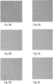
- Table 3 Comparison experiments Print example Ink Fig Crystal P1 Ex 1 5A Smaller crystals P2 Ex 2 5B Smaller crystals P3 Ex 3 5C Smaller crystals P4 CE 1 5D Larger crystals P5 CE 2 5E Larger crystals P6 CE 3 5F Larger crystals
- plurality is defined as two or more than two.
- another is defined as at least a second or more.
- the terms including and/or having, as used herein, are defined as comprising (i.e., open language).
- coupled is defined as connected, although not necessarily directly.
Landscapes
- Chemical & Material Sciences (AREA)
- Life Sciences & Earth Sciences (AREA)
- Engineering & Computer Science (AREA)
- Materials Engineering (AREA)
- Wood Science & Technology (AREA)
- Organic Chemistry (AREA)
- Health & Medical Sciences (AREA)
- General Health & Medical Sciences (AREA)
- Toxicology (AREA)
- Ink Jet (AREA)
Abstract
The present invention relates to a radiation-curable ink composition. The present invention further relates to a method for preparing a radiation-curable ink composition. In addition, the present invention relates to a method for applying an image onto a recording medium.
Description
- The present invention relates to a radiation-curable ink composition. The present invention further relates to a method for preparing a radiation-curable ink composition. In addition, the present invention relates to a method for applying an image onto a recording medium.
- Radiation-curable ink compositions are known in the art. These ink compositions comprise one or more radiation curable components. A special class of radiation curable ink compositions are radiation curable gel ink compositions. These inks are fluid at elevated temperature and become solid -even if not yet cured- at lower temperatures. These inks are typically jetted at elevated temperatures. Gel inks may become solid or semi-solid upon cooling down on a recording medium, e.g. a sheet of paper. As a result, spread of a droplet of ink on the recording medium may be decreased and color bleeding may be prevented.
- Radiation curable gel ink compositions typically comprise a gelling agent. The gelling agent provides the ink composition with gelling property. The gelling process is a complex process. The gelling process may influence the microstructure of the ink layer, which may influence the appearance of the ink layer. For example, the gloss level of the ink layer may be influenced by the gelling process. Suitably controlling the gelling process is difficult, especially in cases wherein the temperature of the recording medium during the printing process is not controlled. The temperature of the recording medium may change and consequently, the gloss level of prints made may change. This is unwanted.
- It is therefore an object of the invention to provide an ink composition that results in prints having a more stable gloss level, also at varying temperature of the recording medium.
- It is a further object of the invention to provide a corresponding method for applying an image onto a recording medium.
- The object of the invention is achieved in a radiation-curable ink composition, wherein the radiation-curable ink composition comprises at least one radiation-curable component and a gelling agent, the at least one radiation-curable component being present in an amount of 55 wt% or more, based on the total weight of the radiation-curable ink composition, wherein the radiation-curable ink composition further comprises a polyalkylene wax, wherein the polyalkylene wax has a molecular weight of 1000 g/mole or less.
- The radiation curable inkjet ink composition may comprise at least one radiation curable component. A radiation-curable component is a component that may react (e.g. polymerize) under influence of suitable radiation, such as electromagnetic radiation, e.g. ultraviolet (UV) radiation. The at least one radiation-curable component may comprise radiation-curable monomers and/or radiation-curable oligomers.
- The monomers and oligomers may be monofunctional (i.e. one polymerizable group per molecule), difunctional (i.e. two polymerizable groups per molecule), trifunctional (i.e. three polymerizable groups per molecule), tetrafunctional ( i.e. four polymerizable groups per molecule), or multifunctional (i.e. five or more polymerizable groups per molecule).
- Examples of radiation-curable monomers are (meth)acrylates, epoxides, vinyls, vinylethers, vinyl esters, vinylether acrylates, allyl ethers, allyl esters, acrylamides, methacrylamides, styrenes, maleates, fumarates and itaconates.
- Examples of radiation-curable oligomers include urethane acrylate oligomers, polyester oligomers, amine functionalized oligomers, polyether oligomers, polyamide oligomers, acrylate oligomers and epoxy based materials such as bisphenol A epoxy acrylates and epoxy acrylates.
- Preferably, the one or more radiation-curable components may comprise one or more acrylates. Preferably, the one or more radiation-curable components may comprise a monofunctional components and a non-monofunctional component, such as a difunctional, trifunctional, tetrafunctional and polyfunctional component.
- Further, the radiation-curable matrix may comprise at least one amine acrylate. Amine acrylates are also known as acrylated amines. Amine acrylates may improve the surface curing of the ink layer upon exposure to radiation, such as UV radiation.
- The ink composition may comprise one type of radiation curable compound or alternatively, the radiation curable medium may comprise a mixture of radiation curable compounds.
- The at least one radiation-curable component may be present in an amount of at least 55 wt%, based on the total weight of the radiation-curable ink composition. Preferably, the at least one radiation-curable component may be present in an amount of at least 60 wt%, based on the total weight of the radiation-curable ink composition, such as an amount of at least 65 wt%, based on the total weight of the radiation-curable ink composition, for example an amount of at least 70 wt%, based on the total weight of the radiation-curable ink composition.
- Preferably, the at least one radiation-curable component may be present in an amount of 95 wt% or less, based on the total weight of the radiation-curable ink composition. More preferably, the at least one radiation-curable component may be present in an amount of 90 wt% or less, based on the total weight of the radiation-curable ink composition.
- In case the radiation-curable ink composition comprises only one radiation-curable component, the radiation-curable component may be present in an amount of at least 55 wt%, based on the total weight of the radiation-curable ink composition. In case the radiation-curable ink composition comprises a plurality of radiation-curable components, the total amount of the plurality of radiation-curable components may be at least 55 wt%, based on the total weight of the radiation-curable ink composition.
- In case the radiation-curable ink composition comprises less than 55wt% of the at least one radiation-curable component, the robustness of the image formed after printing and curing may be insufficient.
- The ink further comprises a gelling agent. Gelling agents are also known in the art as gellants or thickeners. The presence of a gelling agent can cause a viscosity increase in the inkjet ink composition upon cooling of the ink composition. The viscosity increase in the ink composition should be sufficient, to adequately control droplet spreading. Examples of gellants used in gelling radiation curable inkjet ink compositions are waxes, such as paraffin wax, microcrystalline wax, polyethylene waxes, polypropylene waxes, and natural waxes, such as animal-based waxes or plant-based waxes, fatty acids, fatty alcohols, ketones, fatty acid esters and fatty acid amides. Because gelling inks have reduced spread of ink on the recording medium, due to their gelling property, it may not be necessary to cure the ink droplets immediately after applying them onto the recording medium. It is possible to keep the droplets in an uncured state on the recording medium, without color bleeding occurring.
- Polylakylene waxes are a class of waxes based on alkylene polymers or alkylene copolymers. Examples of alkylene polymers are polyethylene and polypropylene. Ethylene-propylene copolymers are an example of alkylene copolymers. The polywax according to the present invention has a molecular weight of 1000 g/mole or less. The molecular weight of the polyalkylene wax may be the number average molecular weight (Mn) of the polyalkylene wax.
- Commercially available examples of polyalkylene waxes having a molecular weight of 1000 g/mole or less include, but are not limited to Polywax (R)1000, Polywax (R)850, Polywax (R)725, Polywax (R) 655 , Polywax (R) 600, Polywax (R)500 and Polywax (R)400.
- It was surprisingly found that an ink composition comprising a gelling agent as well as a polyalkylene wax having a molecular weight of 1000 g/mole or less, results in prints having a higher gloss level.
- In an embodiment, the polyalkylene wax is a linear poly-alkylene wax.
- In an embodiment, the polyalkylene wax is a polyethylene wax.
- In a further embodiment, the polyalkylene wax is a linear polyethylene wax.
- The radiation curable inkjet ink composition may further comprise a colorant, such as a pigment, a dye or a mixture thereof. Further, the radiation curable inkjet ink composition may comprise a mixture of dyes and/or a mixture of pigments. The colorant may provide the ink composition with a predetermined color. The colorant may be a cyan, magenta, black, yellow, brown orange, green, blue, red, purple or white colorant.
- The radiation curable medium may optionally comprise at least one inhibitor. An inhibitor is a component that prevent (inhibits) unwanted polymerization of the radiation curable compound. Inhibitors may be added to the radiation curable inkjet ink composition to increase the shelf life on the ink composition.
- The radiation curable medium may optionally comprise at least one photo initiator. A photo initiator is a component that improves the efficiency of curing; i.e. increases the polymerization rate when the ink composition is irradiated with suitable radiation, such as UV radiation.
- The radiation curable medium may optionally comprise a solvent, such as water or an organic solvent. The solvent may be added to the radiation curable medium to tune ink properties, such as viscosity.
- Further, additional components may be added to the radiation curable medium. For example, the radiation curable medium may comprise surfactants, antibacterial components and anti-fungi components.
- In an embodiment, the gelling agent is a fatty acid ester. Fatty acids are suitable for forming esters, when reacted with a compound comprising an hydroxyl functional group. The fatty acids may be saturated or non-saturated fatty acids. Non-saturated fatty acids may be monounsaturated fatty acids or polyunsaturated fatty acids. Non-saturated fatty acids comprise an alkene functional group. Upon curing of the ink, the alkene functional group may react and the ester compound may be incorporated in the network formed by the radiation-curable component. Preferably, the fatty acid is a saturated fatty acid. When the compound B is a fatty acid, no so-called blooming of the ink may occur. Blooming is an unwanted phenomena that may occur in ink composition, such as radiation-curable ink composition comprising a gelling agent. After being applied onto a recording medium, a gelling agent present in the ink may cool down and may solidify, thereby forming a three-dimensional network that increases the viscosity of the ink. However, in the course of time, the gelling agent may migrate to the surface of the ink layer, which may result in matt print appearance. The phenomenon of decreased gloss due to migration of the gelling agent is known as "blooming". Without wanting to be bound to any theory, it is believed that by selecting compound B to be a fatty acid, an ester compound is obtained, that results in an ink composition that does not show blooming.
- Preferably, the gellant is an ester obtainable by a condensation reaction between a fatty acid and a component selected from the group consisting of pentaerythritol, cyclodextrine, glycerol, dipentaerythritol, 2-(hydroxymethyl)-2-methylpropane-1,3-diol, 2-ethyl-2-(hydroxymethyl)propane-1,3-diol, 2-(hydroxymethyl)propane-1,3-diol, trimethylolethane, trimethylolpropane, trimethylolbutane and trimethylolpentane.
- In a further embodiment, the gelling agent is a fatty acid ester of pentaerythritol. Fatty acid esters of pentaerythritol may be suitably used as gelling agent for a radiation-curable ink composition. Examples of fatty acid esters of pentaerythritol include pentaerythritoltetralaurate, pentaerythritoltetramyristate, pentaerythritoltetrapalmitate, pentaerythritoltetrastearate, pentaerythritoltetra-arachidate, pentaerythritoltetrabehenate, pentaerythritoltetralignocerate and pentaerythritoltetracerotate.
- In an embodiment, wherein the gelling agent is present in an amount of from 0.1 wt% to 15 wt% based on the total weight of the radiation-curable ink composition.
- Preferably, the gelling agent may be present in an amount of from 0.2 wt% to 10 wt% based on the total weight of the ink composition, more preferably from 0.4 wt% to 5 wt% based on the total weight of the ink composition.
- In case the amount of gellant is less than 0.1 wt%, based on the total weight of the radiation-curable ink composition, then the radiation-curable ink composition may not undergo a phase change upon application onto a recording medium. In case the amount of gellant is more than 15 wt%, based on the total weight of the radiation-curable ink composition, then the radiation-curable ink composition may be difficult to jet using an inkjet print head
- In an embodiment, the polyalkylene wax is present in an amount of from 0.01 wt% to 5 wt% based on the total amount of the radiation-curable ink composition. Preferably, the polyalkylene wax is present in an amount of from 0. 1 wt% to 2 wt% based on the total amount of the radiation-curable ink composition.
- In an aspect of the invention, a method for preparing a radiation-curable ink composition is provided, the method comprising the steps of:
- providing at least one radiation curable component, the at least one radiation-curable component being present in an amount of 55 wt% or more, based on the total weight of the radiation-curable ink composition;
- providing a gelling agent;
- providing a polyalkylene wax, the polyalkylene wax having a molecular weight of 1000 g/mole or less;
- mixing the radiation curable component, the gelling agent and the polyalkylene wax.
- The method may result in the preparation of the radiation-curable ink composition according to the present invention.
- In a further aspect of the invention, a method for applying an image onto a recording medium is provided, the method comprising the steps of:
- a. jetting droplets of a radiation-curable ink composition according to the present invention onto the recording medium;
- b. curing the radiation-curable ink composition by irradiating the ink composition using UV radiation.
- In the method, in step a), an image is applied to the recording medium. The image may be applied using an ink composition according to the present invention. The ink composition may be applied onto the recording medium in a predetermined fashion, e.g. in accordance with image files stored on suitable storing means. The image may be applied for example by jetting droplets of the radiation-curable inkjet ink composition using an inkjet print head. The recording medium may be a sheet-like medium, such as a sheet of paper or a sheet of vinyl. Alternatively, the recording medium may be a web, for example an endless belt. The web may be made of a suitable material. Optionally, the image may be dried after it has been applied onto the intermediate transfer member. In the method, in step b), the radiation-curable inkjet ink composition is cured by irradiating the ink composition using UV radiation. The inkjet ink composition may be irradiated using a suitable source of radiation, such as a halogen lamp, a mercury lamp and/or a LED lamp. Optionally, a plurality of sources of radiation may be used to irradiate the inkjet ink composition.
- In an embodiment, a time interval between jetting droplets of the radiation-curable ink composition and curing the radiation-curable ink composition is at least 30 seconds. The time interval between applying the radiation-curable ink and curing the radiation-curable ink may be at least 30 seconds, preferably at least 60 seconds. In case the time interval between applying the radiation-curable gel ink and curing the radiation-curable gel ink is less than 30 seconds, an image may be formed comprising a plurality of layers, without intermediate curing of the ink. In case the time interval between applying the ink and curing the ink is at least 30 seconds, the ink may spread sufficiently, resulting in good image quality.
- The present invention will become more fully understood from the detailed description given herein below and the accompanying drawings which are given by way of illustration only, and thus are not limitative of the present invention, and wherein:
-
Fig. 1 is a schematic perspective view of a first example of a printing system according to the present invention in a first printing mode; -
Fig. 2 is a schematic perspective view of a second example of a printing system according to the present invention in a second printing mode; -
Fig. 3 is a schematic perspective view of a third example of a printing system according to the present invention in a third printing mode; -
Fig. 4 is a schematic diagram of a control unit of a reprographic system according toFig. 1, 2 or3 ; -
Fig 5A-5F show pictures of the comparison experiments. - In the drawings, same reference numerals refer to same elements.
- The present invention will now be described with reference to the accompanying drawings, wherein the same reference numerals have been used to identify the same or similar elements throughout the several views.
-
Fig. 1 shows a printing apparatus. A printing apparatus is also known as printer. Theprinting apparatus 1 comprises anscanning printing unit 7 for printing on arecording medium 15. Therecording medium 15 inFig. 1 is a relatively rigid substrate, such as a panel. Therecording medium 15 is supplied from amedia input unit 14, which may be configured for storing a plurality ofsuch print media 15 and supplying these to theprinter 1. Theprinter 1 comprises amedium support 4.Printer 1 may further comprise transport means for receiving and transporting therecording medium 15 along thescanning printing unit 7. InFig. 1 , the medium support is embodied as anendless belt 4. The endless belt is anendless transport belt 4 supported on a plurality ofsupport rollers support rollers belt 4. Thebelt 4 is therefore configured to support and transport the recording medium. Additionally, one or more one of thesupport rollers belt 4. Thescanning printing unit 7 may be provided with asensor 8, such as a CCD camera, to determine the relative position ofbelt 4 and/or therecording medium 15. Data from saidsensor 8 may be applied to control the position of thebelt 4 and/or therecording medium 15. Thebelt 4 is further provided with through-holes and asuction box 5 in connection with a suction source (not shown), such that an underpressure may be applied to therecording medium 15 via the through-holes in thebelt 4. The underpressure adheres therecording medium 15 flatly to thebelt 4 and prevents displacement of therecording medium 15 with respect to thebelt 4. Due to this holding thebelt 4 is able to transport therecording medium 15. It will be appreciated that other suitable transport means, such as rollers, steppers, etc, may alternatively be applied. Therecording medium 15 may be transported stepwise and/or in continuous movement. Thescanning printing unit 7 is configured to translate along afirst guide beam 6 in a scanning direction. The scanning direction is perpendicular to the direction in which the print medium is transported by thebelt 4. Thescanning printing unit 7 holds a plurality of print heads (not shown), which are configured to jet a plurality of different marking materials (different colors of ink, primers, coatings, etc.) on therecording medium 15. Each marking material for use in thescanning printing unit 7 is stored in one of a plurality of containers arranged in fluid connection with the respective print heads for supplying marking material to said print heads to print an image on therecording medium 15. - The application of the marking material, such as the radiation-curable ink from the printing units is performed in accordance with data provided in the respective print job. The printing unit may comprise one or more inkjet print heads. The timing by which the droplets of marking material are released from the one or more print heads determines their position on the
recording medium 15. The timing may be adjusted based on the position of thescanning printing unit 7 along thefirst guide beam 6. The above mentionedsensor 8 may therein be applied to determine the relative position and/or velocity of thescanning printing unit 7 with respect to therecording medium 15. Based upon data from thesensor 8, the release timing of the marking material may be adjusted. - Upon ejection of the marking material, some marking material may be spilled and stay on a nozzle surface of the print heads. The marking material present on the nozzle surface, may negatively influence the ejection of droplets and the placement of these droplets on the
recording medium 15. Therefore, it may be advantageous to remove excess of marking material from the nozzle surface. The excess of marking material may be removed for example by wiping with a wiper and/or by application of a suitable anti-wetting property of the surface, e.g. provided by a coating. - The marking materials may require treatment to properly fixate them on the print medium. Thereto, a fixation unit is provided downstream of the
scanning printing unit 7. The fixation unit may emit radiation to facilitate the marking material fixation process. In the example ofFig. 1 , the fixation unit is page-wide curing array 10. The page-wide curing array 10 extends in the main scanning direction. The page-wide curing array does not move in operation in the main scanning direction. The page-wide array may move in the direction of medium transport, which is a direction perpendicular to the scanning direction. In an alternative embodiment (not shown), the fixation unit may be a scanning fixation unit, that in operation moves in reciprocation in the scanning direction. The page-wide curing array 10 is configured to in operation emit radiation of certain frequencies, which interacts with the marking materials, for example UV light in case of UV-curable inks. Optionally (not shown), thescanning printing unit 7 may be provided with a further fixation unit on the same carriage which holds the print heads. This further fixation unit can be used to (partially) cure and/or harden the marking materials, independent of or interaction with the page-wide curing array 10. - After printing and fixation, the
recording medium 15 is transported to a receiving unit (not shown). The receiving unit may comprise a take-up roller for winding up therecording medium 15, a receiving tray for supporting sheets ofrecording medium 15, or a rigid media handler, similar to themedia input unit 14. Optionally, the receiving unit may comprise processing means for processing themedium 8, 9 after printing, e.g. a post-treatment device such as a coater, a folder, a cutter, or a puncher. -
Printing apparatus 1 furthermore comprises auser interface 11 for receiving print jobs and optionally for manipulating print jobs. The localuser interface unit 11 is integrated to the print engine and may comprise a display unit and a control panel. Alternatively, the control panel may be integrated in the display unit, for example in the form of a touch-screen control panel. The localuser interface unit 11 is connected to acontrol unit 12 connected to theprinter 1. Thecontrol unit 12, for example a computer, comprises a processor adapted to issue commands to theprinter 1, for example for controlling the print process. Theprinter 1 may optionally be connected to a network. The connection to the network can be via cable or wireless. Theprinter 1 may receive printing jobs via the network. Further, optionally, thecontrol unit 12 of theprinter 1 may be provided with an input port, such as a USB port, so printing jobs may be sent to theprinter 1 via this input port. - The
printer 1 inFig. 1 is a so-called hybrid printer, capable of handling both flexible media and rigid substrates. InFig. 1 , theprinter 1 operates in a first print mode, wherein theprinter 1 is configured for transporting rigid substrates, such as therecording medium 15. Suchrigid print media 15 may be panels, for example panels for doors or walls, corrugated media, plates formed of plastic or metal, etc. To handle theserigid print media 15, theprinter 1 inFig. 1 is configured with a substantially linear transport path: from themedia input device 14, therecording medium 15 moves forward along thescanning printing unit 7 at a at substantially constant height. Themedia input unit 14 and the receiving unit are positioned at the level of the medium support surface of thebelt 4. InFig. 2 , aflexible web medium 16 is supplied to theprinter 1, whichweb medium 16 may be composed of e.g. paper, label stock, coated paper, plastic or textile. Theweb medium 16 is supplied from theinput roller 2A and extends across thebelt 4 to the take-uproller 2B, where theweb medium 16 is re-wound. Theprinter 1 is configured to swiftly and efficiently switch between print modes. -
Figure 3 shows a printer similar to the printer shown inFig. 1 . The printer shown inFig. 3 comprises ascanning curing unit 10. Thescanning curing unit 10 is configured to move in reciprocation in the scanning direction alongguide rail 17. Thescanning curing unit 10 comprises at least one radiation emitting unit (not shown). - An embodiment of the
control unit 12 is in more detail presented inFig. 4 . As shown inFig. 4 , thecontrol unit 12 comprises a Central Processing Unit (CPU) 31, a Graphical Processor Unit (GPU) 32, a Random Access Memory (RAM) 33, a Read Only Memory (ROM) 34, anetwork unit 36, aninterface unit 37, a hard disk (HD) 35 and animage processing unit 39 such as a Raster Image Processor (RIP). The aforementioned units 31 - 37 are interconnected through abus system 38. However, thecontrol unit 12 may also be a distributed control unit. - The
CPU 31 controls theprinting system 1 in accordance with control programs stored in theROM 34 or on theHD 35 and the localuser interface panel 5. TheCPU 31 also controls theimage processing unit 39 and theGPU 32. TheROM 34 stores programs and data such as boot program, set-up program, various set-up data or the like, which are to be read out and executed by theCPU 31. Thehard disk 35 is an example of a non-volatile storage unit for storing and saving programs and data which make theCPU 31 execute a print process to be described later. Thehard disk 35 also comprises an area for saving the data of externally submitted print jobs. The programs and data on theHD 35 are read out onto theRAM 33 by theCPU 31 as needed. TheRAM 33 has an area for temporarily storing the programs and data read out from theROM 34 andHD 35 by theCPU 31, and a work area which is used by theCPU 31 to execute various processes. Theinterface unit 37 connects thecontrol unit 12 to the client devices, such asscan device 19 and to theprinting system 1. Thenetwork unit 36 connects thecontrol unit 12 to the network N and is designed to provide communication with the workstations (not shown) and withother devices 19 reachable via the network N. Theimage processing unit 39 may be implemented as a software component running on an operation system of thecontrol unit 12 or as a firmware program, for example embodied in a field-programmable gate array (FPGA) or an application-specific integrated circuit (ASIC). Theimage processing unit 39 has functions for reading, interpreting and rasterizing the print job data. Said print job data contains image data to be printed (i.e. fonts and graphics that describe the content of the document to be printed, described in a Page Description Language or the like), image processing attributes and print settings. - SR 355, SR 531 and CN991 were obtained from Sartomer. BYK 333 was obtained from BYK. Phenothiazine, 1-docosanol and stearone were obtained from Sigma Aldrich. Pentaerythritoltetrastearate was obtained from NOF and polywax 500 was obtained from NuCera. All materials were used as obtained, unless stated otherwise.
- Print samples were prepared by applying ink onto a glass plate using a pipette. The plate provided with the ink was heated to 80°C and subsequently cooled down to room temperature. The print samples were put under a Olympus Light Microscope equipped with QICAM Fast 1394 camera. Pictures were taken; the magnification of all pictures are at 50×.
- Ink examples 1, 2 and 3 (
Ex 1, Ex 2 and Ex 3) were prepared by providing the ingredients listed in table 1 below and mixing the ingredients.Table 1: Ink examples 1-3 Component Ex 1 Ex 2 Ex 3 SR 355 1.58 gr 1.58 gr 1.58 gr SR 531 69.15 gr 69.15 gr 69.15 gr CN991 27.08 gr 27.08 gr 27.08 gr BYK 333 0.53 gr 0.53 gr 0.53 gr phenothiazine 0.08 gr 0.08 gr 0.08 gr pentaerythritoltetrastearate 1.40 gr 0 0 1-docosanol 0 1.40 gr 0 stearone 0 0 1.40 gr polywax 500 0.20 gr 0.20 gr 0.20 gr - Ink examples 1-3 each comprise a gelling agent and polyalkylene wax. Hence, ink examples 1-3 are examples according to the present invention.
- Comparative ink examples 1, 2 and 3 (
CE 1, CE 2 and CE 3): Comparative ink example 1 was prepared by providing the ingredients listed in table 2 below and mixing the ingredients.Table 2: Comparative ink example 1-3 Component CE 1 CE 2 CE 3 SR 355 1.59 gr 1.59 gr 1.59 gr SR 531 69.29 gr 69.29 gr 69.29 gr CN991 27.13 gr 27.13 gr 27.13 gr BYK 333 0.53 gr 0.53 gr 0.53 gr phenothiazine 0.08 gr 0.08 gr 0.08 gr pentaerythritoltetrastearate 1.40 gr 0 0 1-docosanol 0 1.40 gr 0 stearone 0 0 1.40 gr - Comparative ink examples 1-3 each comprise a gelling agent, but do not comprise a polyalkylene wax. Hence, comparative ink examples 1-3 are not examples according to the present invention.
- Printing examples P1-P6 were prepared using the ink examples and comparative ink examples.
- The experiments and results are summarized in table 3.
Table 3: Comparison experiments Print example Ink Fig Crystal P1 Ex 1 5A Smaller crystals P2 Ex 2 5B Smaller crystals P3 Ex 3 5C Smaller crystals P4 CE 1 5D Larger crystals P5 CE 2 5E Larger crystals P6 CE 3 5F Larger crystals - Analysis of the print examples showed that the print samples made with ink according to the present invention (Ex 1- Ex 3) form smaller crystals compared to samples made with ink not according to the present invention (CE 1- CE 3). Ink layers with smaller crystals generally show a high gloss, whereas ink layers with larger crystals generally show a lower gloss.
- Detailed embodiments of the present invention are disclosed herein; however, it is to be understood that the disclosed embodiments are merely exemplary of the invention, which can be embodied in various forms. Therefore, specific structural and functional details disclosed herein are not to be interpreted as limiting, but merely as a basis for the claims and as a representative basis for teaching one skilled in the art to variously employ the present invention in virtually and appropriately detailed structure. In particular, features presented and described in separate dependent claims may be applied in combination and any combination of such claims are herewith disclosed. Further, the terms and phrases used herein are not intended to be limiting; but rather, to provide an understandable description of the invention. The terms "a" or "an", as used herein, are defined as one or more than one. The term plurality, as used herein, is defined as two or more than two. The term another, as used herein, is defined as at least a second or more. The terms including and/or having, as used herein, are defined as comprising (i.e., open language). The term coupled, as used herein, is defined as connected, although not necessarily directly.
Claims (8)
- Radiation-curable ink composition, wherein the radiation-curable ink composition comprises at least one radiation-curable component and a gelling agent, the at least one radiation-curable component being present in an amount of 55 wt% or more, based on the total weight of the radiation-curable ink composition, wherein the radiation-curable ink composition further comprises a polyalkylene wax, wherein the polyalkylene wax has a molecular weight of 1000 g/mole or less.
- Radiation-curable ink composition according to claim 1, wherein the gelling agent is a fatty acid ester.
- Radiation-curable ink composition according to claim 2, wherein the gelling agent is a fatty acid ester of pentaerythritol.
- Radiation-curable ink composition according to any of the preceding claims, wherein the gelling agent is present in an amount of from 0.1 wt% to 15 wt% based on the total amount of the radiation-curable ink composition.
- Radiation-curable ink composition according to any of the preceding claims, wherein the polyalkylene wax is present in an amount of from 0.01 wt% to 5 wt% based on the total amount of the radiation-curable ink composition.
- Method for preparing a radiation-curable ink composition according to claim 1 - 5, the method comprising the steps of:• providing at least one radiation curable component, the at least one radiation-curable component being present in an amount of 55 wt% or more, based on the total weight of the radiation-curable ink composition;• providing a gelling agent;• providing a polyalkylene wax, the polyalkylene wax having a molecular weight of 1000 g/mole or less;• mixing the radiation curable component, the gelling agent and the polyalkylene wax.
- Method for applying an image onto a recording medium, the method comprising the steps of :a. jetting droplets of a radiation-curable ink composition according to any of claims 1- 5 onto the recording medium;b. curing the radiation-curable ink composition by irradiating the ink composition using UV radiation.
- Method according to claim 7, wherein a time interval between jetting droplets of the radiation-curable ink composition and curing the radiation-curable ink composition is at least 30 seconds.
Applications Claiming Priority (1)
| Application Number | Priority Date | Filing Date | Title |
|---|---|---|---|
| EP23183746 | 2023-07-05 |
Publications (1)
| Publication Number | Publication Date |
|---|---|
| EP4488341A1 true EP4488341A1 (en) | 2025-01-08 |
Family
ID=87158008
Family Applications (1)
| Application Number | Title | Priority Date | Filing Date |
|---|---|---|---|
| EP24185071.8A Pending EP4488341A1 (en) | 2023-07-05 | 2024-06-27 | Radiation-curable ink composition, method for preparing the same and method for applying an image onto a recording medium |
Country Status (2)
| Country | Link |
|---|---|
| US (1) | US20250011611A1 (en) |
| EP (1) | EP4488341A1 (en) |
Citations (8)
| Publication number | Priority date | Publication date | Assignee | Title |
|---|---|---|---|---|
| US20060117993A1 (en) * | 2004-12-04 | 2006-06-08 | Xerox Corporation | Phase change inks containing curable trans-1,2-cyclohexane bis(urea-urethane) compounds |
| US20070131138A1 (en) * | 2005-12-12 | 2007-06-14 | Xerox Corporation | Carbon black inks and method for making same |
| US20080000384A1 (en) * | 2006-06-28 | 2008-01-03 | Xerox Corporation | Radiation curable ink containing gellant and radiation curable wax |
| EP1918294A1 (en) * | 2006-10-27 | 2008-05-07 | Xerox Corporation | Nanostructured Particles, Phase Change Inks Including Same and Methods for Making Same |
| EP2161312A1 (en) * | 2008-09-04 | 2010-03-10 | Xerox Corporation | Ultra-Violet Curable Gellant Inks for Three-Dimensional Printing and Digital Fabrication Applications |
| US20100124611A1 (en) * | 2008-11-17 | 2010-05-20 | Xerox Corporation | Phase Change Inks Containing Graphene-Based Carbon Allotrope Colorants |
| US20110152396A1 (en) * | 2009-12-18 | 2011-06-23 | Xerox Corporation | Curable Solid Overcoat Compositions |
| EP3587514A1 (en) * | 2018-06-26 | 2020-01-01 | Konica Minolta, Inc. | Actinic radiation-curable inkjet ink, method for producing actinic radiation-curable inkjet ink, and image forming method |
Family Cites Families (2)
| Publication number | Priority date | Publication date | Assignee | Title |
|---|---|---|---|---|
| US10308042B2 (en) * | 2016-03-30 | 2019-06-04 | Océ Holding B. V. | Radiation-curable inkjet ink composition |
| RU2746938C2 (en) * | 2016-12-09 | 2021-04-22 | Сикпа Холдинг Са | Curing inks for offset and letterpress printing with low energy consumption and printing method |
-
2024
- 2024-06-27 EP EP24185071.8A patent/EP4488341A1/en active Pending
- 2024-07-03 US US18/763,275 patent/US20250011611A1/en active Pending
Patent Citations (8)
| Publication number | Priority date | Publication date | Assignee | Title |
|---|---|---|---|---|
| US20060117993A1 (en) * | 2004-12-04 | 2006-06-08 | Xerox Corporation | Phase change inks containing curable trans-1,2-cyclohexane bis(urea-urethane) compounds |
| US20070131138A1 (en) * | 2005-12-12 | 2007-06-14 | Xerox Corporation | Carbon black inks and method for making same |
| US20080000384A1 (en) * | 2006-06-28 | 2008-01-03 | Xerox Corporation | Radiation curable ink containing gellant and radiation curable wax |
| EP1918294A1 (en) * | 2006-10-27 | 2008-05-07 | Xerox Corporation | Nanostructured Particles, Phase Change Inks Including Same and Methods for Making Same |
| EP2161312A1 (en) * | 2008-09-04 | 2010-03-10 | Xerox Corporation | Ultra-Violet Curable Gellant Inks for Three-Dimensional Printing and Digital Fabrication Applications |
| US20100124611A1 (en) * | 2008-11-17 | 2010-05-20 | Xerox Corporation | Phase Change Inks Containing Graphene-Based Carbon Allotrope Colorants |
| US20110152396A1 (en) * | 2009-12-18 | 2011-06-23 | Xerox Corporation | Curable Solid Overcoat Compositions |
| EP3587514A1 (en) * | 2018-06-26 | 2020-01-01 | Konica Minolta, Inc. | Actinic radiation-curable inkjet ink, method for producing actinic radiation-curable inkjet ink, and image forming method |
Also Published As
| Publication number | Publication date |
|---|---|
| US20250011611A1 (en) | 2025-01-09 |
Similar Documents
| Publication | Publication Date | Title |
|---|---|---|
| EP3234038B1 (en) | Ink composition | |
| JP2004175906A (en) | Active ray-curable inkjet solventless ink and method of image formation and inkjet printer | |
| JP2008105378A (en) | Inkjet recording method and inkjet recording apparatus | |
| JPWO2006129530A1 (en) | Ultraviolet curable inkjet ink, inkjet recording method, and inkjet recording apparatus | |
| JP2024133484A (en) | Method for printing | |
| EP3173447A1 (en) | Uv curable gelling ink formulation with low wax migration in cured state | |
| JP2003237217A (en) | Apparatus and method for ink jet recording | |
| CN113226778A (en) | Liquid discharge device and liquid discharge method | |
| US20250011611A1 (en) | Radiation-curable ink composition, method for preparing the same and method for applying an image onto a recording medium | |
| EP3677651B1 (en) | Radiation-curable inkjet ink composition | |
| EP3517582B1 (en) | Radiation-curable inkjet ink composition | |
| EP3447097B1 (en) | Radiation-curable inkjet ink composition | |
| EP4431574A1 (en) | Radiation-curable ink composition, method for preparing the same and method for applying an image onto a recording medium | |
| EP4538046A1 (en) | Method for applying an image, use of a photo initiator, printing apparatus and software product | |
| WO2025190789A1 (en) | Printing method and printer | |
| EP4606871A1 (en) | Radiation-curable inkjet ink composition | |
| EP4420888A1 (en) | Method for operating a printing apparatus, printing apparatus and software product | |
| WO2025190848A1 (en) | Ink composition, ink set, method for preparing an ink composition, printing method and printer | |
| EP4647472A1 (en) | Radiation-curable component, ink composition, printing method and printed object | |
| US20230406008A1 (en) | Printer apparatus and print method for preparing an image having matt portions and glossy portions | |
| EP3613815B1 (en) | Radiation curable ink composition | |
| EP3608374B1 (en) | Radiation curable ink composition | |
| JP2004034440A (en) | Inkjet imaging method | |
| JP2023032078A (en) | Inkjet image forming method and inkjet image forming apparatus | |
| JP2021062530A (en) | Printing device and printing method |
Legal Events
| Date | Code | Title | Description |
|---|---|---|---|
| PUAI | Public reference made under article 153(3) epc to a published international application that has entered the european phase |
Free format text: ORIGINAL CODE: 0009012 |
|
| STAA | Information on the status of an ep patent application or granted ep patent |
Free format text: STATUS: THE APPLICATION HAS BEEN PUBLISHED |
|
| AK | Designated contracting states |
Kind code of ref document: A1 Designated state(s): AL AT BE BG CH CY CZ DE DK EE ES FI FR GB GR HR HU IE IS IT LI LT LU LV MC ME MK MT NL NO PL PT RO RS SE SI SK SM TR |
|
| STAA | Information on the status of an ep patent application or granted ep patent |
Free format text: STATUS: REQUEST FOR EXAMINATION WAS MADE |
|
| 17P | Request for examination filed |
Effective date: 20250708 |