EP4488178A1 - Assemblage d'un mât d'accrochage avec un moteur d'aéronef - Google Patents
Assemblage d'un mât d'accrochage avec un moteur d'aéronef Download PDFInfo
- Publication number
- EP4488178A1 EP4488178A1 EP24182584.3A EP24182584A EP4488178A1 EP 4488178 A1 EP4488178 A1 EP 4488178A1 EP 24182584 A EP24182584 A EP 24182584A EP 4488178 A1 EP4488178 A1 EP 4488178A1
- Authority
- EP
- European Patent Office
- Prior art keywords
- engine
- port
- starboard
- casing
- yoke
- Prior art date
- Legal status (The legal status is an assumption and is not a legal conclusion. Google has not performed a legal analysis and makes no representation as to the accuracy of the status listed.)
- Granted
Links
Images

Classifications
-
- B—PERFORMING OPERATIONS; TRANSPORTING
- B64—AIRCRAFT; AVIATION; COSMONAUTICS
- B64D—EQUIPMENT FOR FITTING IN OR TO AIRCRAFT; FLIGHT SUITS; PARACHUTES; ARRANGEMENT OR MOUNTING OF POWER PLANTS OR PROPULSION TRANSMISSIONS IN AIRCRAFT
- B64D27/00—Arrangement or mounting of power plants in aircraft; Aircraft characterised by the type or position of power plants
- B64D27/40—Arrangements for mounting power plants in aircraft
-
- B—PERFORMING OPERATIONS; TRANSPORTING
- B64—AIRCRAFT; AVIATION; COSMONAUTICS
- B64D—EQUIPMENT FOR FITTING IN OR TO AIRCRAFT; FLIGHT SUITS; PARACHUTES; ARRANGEMENT OR MOUNTING OF POWER PLANTS OR PROPULSION TRANSMISSIONS IN AIRCRAFT
- B64D27/00—Arrangement or mounting of power plants in aircraft; Aircraft characterised by the type or position of power plants
- B64D27/40—Arrangements for mounting power plants in aircraft
- B64D27/402—Arrangements for mounting power plants in aircraft comprising box like supporting frames, e.g. pylons or arrangements for embracing the power plant
-
- B—PERFORMING OPERATIONS; TRANSPORTING
- B64—AIRCRAFT; AVIATION; COSMONAUTICS
- B64D—EQUIPMENT FOR FITTING IN OR TO AIRCRAFT; FLIGHT SUITS; PARACHUTES; ARRANGEMENT OR MOUNTING OF POWER PLANTS OR PROPULSION TRANSMISSIONS IN AIRCRAFT
- B64D27/00—Arrangement or mounting of power plants in aircraft; Aircraft characterised by the type or position of power plants
- B64D27/40—Arrangements for mounting power plants in aircraft
- B64D27/404—Suspension arrangements specially adapted for supporting vertical loads
-
- B—PERFORMING OPERATIONS; TRANSPORTING
- B64—AIRCRAFT; AVIATION; COSMONAUTICS
- B64D—EQUIPMENT FOR FITTING IN OR TO AIRCRAFT; FLIGHT SUITS; PARACHUTES; ARRANGEMENT OR MOUNTING OF POWER PLANTS OR PROPULSION TRANSMISSIONS IN AIRCRAFT
- B64D27/00—Arrangement or mounting of power plants in aircraft; Aircraft characterised by the type or position of power plants
- B64D27/40—Arrangements for mounting power plants in aircraft
- B64D27/406—Suspension arrangements specially adapted for supporting thrust loads, e.g. thrust links
Definitions
- the present invention relates to an assembly of a mounting pylon with an aircraft engine, comprising an attachment system in the form of a front engine attachment, where the attachment system is compact, as well as an aircraft comprising at least one such assembly.
- An aircraft typically has at least one engine, in particular a turbojet. Under each wing and for each engine, the aircraft has a reactor pylon which is fixed to the wing structure and which extends below the wing and the engine is suspended under the reactor pylon.
- the engine is housed in a nacelle and attached to the engine pylon via an engine attachment system comprising a front engine suspension attachment on a first interface plane, a rear engine suspension attachment on a second interface plane and a thrust recovery path, which can either be integrated into one of the two aforementioned engine suspension interface planes, or integrated independently into a third interface plane.
- An object of the present invention is to provide a front engine attachment system for an aircraft engine comprising a reactor pylon and an engine casing, where the integration ensures a reduction in the height of the assembly.
- the front male yoke is arranged on the front transverse reinforcement of the attachment mast and the front female yoke is arranged on the engine casing.
- the front female yoke is arranged on the front transverse reinforcement of the attachment mast and the front male yoke is arranged on the engine casing.
- the lower male yoke is arranged on the lower spar of the attachment mast and the lower female yoke is arranged on the engine casing.
- the lower female yoke is arranged on the lower spar of the attachment mast and the lower male yoke is arranged on the engine casing.
- the engine casing takes the form of a crown and each front and lower female yoke of the engine casing is constituted by walls of the casing arranged on either side of the vertical median plane and constituting protrusions of the casing between which the front and lower male yokes of the attachment mast are arranged.
- the front male yoke is made up of two front fittings.
- the lower male yoke is made up of two lower fittings.
- the front engine attachment also comprises second port and starboard connecting rods, the first port and starboard pins also connecting the first port and starboard male yoke with the second port and starboard connecting rod, the second port and starboard pins also connecting the second port and starboard male yoke with the second port and starboard connecting rod, the first and second port and starboard connecting rods being mounted in parallel around the first and second port and starboard male yokes.
- the pins of one of the pairs of the pair comprising the first port pin and the second port pin and the pair comprising the first starboard pin and the second starboard pin connect the attachment pylon to the engine housing in a snug manner
- the pins of the other of the pairs connect the attachment pylon to the engine housing with clearance
- the lower pin connects the attachment pylon to the engine housing in a snug manner
- the front pin connects the attachment pylon to the engine housing with clearance.
- the pins of one of the pairs of the pair comprising the first port pin and the second port pin and the pair comprising the first starboard pin and the second starboard pin connect the attachment pylon to the engine housing in a snug manner
- the pins of the other of the pairs connect the attachment pylon to the engine housing with clearance
- the lower pin connects the attachment pylon to the engine housing with clearance
- the front pin connects the attachment pylon to the engine housing in a snug manner.
- an aircraft comprising an assembly of a suspension pylon with an aircraft engine according to the invention.
- Such a fastening system has a reduced vertical footprint.
- the casing takes the form of a crown and each front and lower female yoke of the casing is constituted by walls of the casing arranged on either side of the vertical median plane and constituting protrusions of the casing between which the front and lower male yokes are arranged.
- the front male yoke is made up of two front fittings, where each front fitting has a front under-bore, where the two front under-bores extend and form the first front bore.
- the lower male yoke is made up of two lower fittings, where each lower fitting has a lower under-bore, where the two lower under-bores extend and form the first lower bore.
- said front engine attachment system also comprises a second port connecting rod having a first and a second bore, where the first port axis is also mounted in the first bore of the second port connecting rod, where the second axis port is also mounted in the second bore of the second port connecting rod, the first and second port connecting rods being mounted in parallel around the first and second port male yokes, and said front engine attachment system also comprises a second starboard connecting rod having a third and a fourth bore, where the first starboard pin is also mounted in the third bore of the second starboard connecting rod, where the second starboard pin is also mounted in the fourth bore of the second starboard connecting rod, the first and second starboard connecting rods being mounted in parallel around the first and second starboard male yokes.
- the axes of one of the pairs among the pair comprising the first port axis and the second port axis and the pair comprising the first starboard axis and the second starboard axis are mounted adjusted in the associated bores
- the axes of the other of the pairs are mounted with a radial clearance in the associated bores
- the lower axis is mounted adjusted in the associated bores
- the front axis is mounted with a radial clearance in the associated bores.
- the axes of one of the pairs among the pair comprising the first port axis and the second port axis and the pair comprising the first starboard axis and the second starboard axis are mounted adjusted in the associated bores
- the axes of the other of the pairs are mounted with a radial clearance in the associated bores
- the lower axis is mounted with a radial clearance in the associated bores
- the front axis is mounted adjusted in the associated bores.
- the invention also provides an aircraft comprising a structure, an engine and a front engine attachment system according to one of the preceding variants, where the engine pylon is fixed to the structure and where the casing is an engine casing.
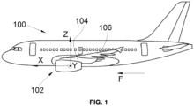
- FIG. 1 shows an aircraft 100 which has an engine 102, in particular a turbojet which is fixed under a mounting pylon, also called a reactor pylon 104, itself fixed under a wing 106.
- engine 102 in particular a turbojet which is fixed under a mounting pylon, also called a reactor pylon 104, itself fixed under a wing 106.
- X is the longitudinal direction of the engine 102 oriented positively in the direction of advancement of the aircraft 100
- Y is the transverse direction of the engine 102 which is horizontal when the aircraft 100 is on the ground
- Z is the vertical direction or vertical height when the aircraft 100 is on the ground, these three directions X, Y and Z being orthogonal to each other.
- the engine 102 generally has a shape of revolution around the longitudinal axis X.
- the aircraft 100 comprises an engine 102 under each wing 106 of the aircraft 100, but it is possible to provide several engines under each wing 106.
- FIG. 2 shows the port portion of an assembly of the attachment pylon 104 with the aircraft engine 102, which comprises a front engine attachment system 150, also called a front engine attachment, for the engine 102 according to the invention, the starboard portion being generally symmetrical to the port portion with respect to a vertical median plane XZ of the assembly.
- the assembly comprises the attachment of a casing 102a of the engine 102 to the engine pylon 104 and of the engine pylon 104 to the structure of the wing 106 and, more generally, to a structure of the aircraft 100.
- the casing 102a is a casing of the engine 102 and here generally takes the form of a cylinder around the longitudinal direction X.
- the engine 102 is not described in more detail because this engine can take any form known to those skilled in the art.
- the assembly is fixed to the structure of the aircraft 100, here the structure of the wing 106, and extends under the wing 106 and supports the engine 102 via the casing 102a of the engine 102.
- a rear engine attachment is fixed between the engine pylon 104 and a rear portion of the engine 102 and it can take any form known to those skilled in the art.
- the reactor mast 104 takes the form of a box which here comprises an upper wall 104a, also called upper spar, a lower wall 104b, also called lower spar, and two side walls 104c-d, also called port side panels and starboard.
- the different walls 104a-d are integral with each other so as to form a box whose vertical section is generally trapezoidal.
- the reactor mast 104 comprises at a front part 163 of the box, a front transverse reinforcement, also called nose 110, fixed at the front part 163 by any known means, such as by welding or by installing bolts.
- the front part 163 corresponds to the front ends of the walls 104a-d.
- the nose 110 has at the vertical median plane XZ and at the front of the nose 110, a front male yoke 112 which is crossed by a first front bore coaxial with a front axis 112a.
- the front transverse reinforcement 110 comprises the front male yoke 112 at the vertical median plane XZ.
- the front transverse reinforcement 110 comprises a front female yoke centered on the vertical median plane XZ.
- the lower wall 110 (or under the nose 110) has at the level of the vertical median plane XZ, a lower male yoke 114 which is crossed by a first lower bore coaxial with a lower axis 114a.
- the lower axis 114a is here parallel to the front axis 112a.
- the lower 114a and front 112a axes both extend in the transverse direction Y perpendicular to the vertical median plane XZ, and therefore extend here generally parallel to the transverse direction Y.
- the lower spar 104b comprises the lower male yoke 114 at the level of the vertical median plane XZ.
- the lower spar 104b comprises a lower female yoke centered on the vertical median plane XZ.
- the transverse reinforcement 110 comprises the lower male yoke 114 at the level of the vertical median plane XZ, under said front transverse reinforcement 110.
- the transverse reinforcement 110 comprises a lower female yoke centered on the vertical median plane XZ, arranged under the transverse reinforcement 110.
- the nose 110 On either side of the vertical median plane XZ, the nose 110 has a lateral stiffener 111 which extends perpendicular to the vertical median plane XZ.
- a port lateral stiffener 111 which comprises a first port male yoke 107 extending orthogonally to the vertical median plane XZ and crossed by a first port bore coaxial with a first port axis 116a and a starboard lateral stiffener which comprises a first starboard male yoke extending orthogonally to the vertical median plane XZ and crossed by a first starboard bore coaxial with a first starboard axis.
- the front transverse reinforcement 110 comprises first port 107 and starboard male yokes extending orthogonally to the vertical median plane XZ.
- the port and starboard side walls or side panels 104c-d each comprise a first port and starboard male yoke 107 extending orthogonally to the vertical median plane XZ.
- the casing 102a here takes the form of a crown and comprises a front female yoke 113 crossed by a second front bore coaxial with the front axis 112a.
- the casing 102a of the engine 102 comprises a front male yoke.
- the casing 102a also has a lower female yoke 115 which is crossed by a second lower bore coaxial with the lower axis 114a.
- the casing 102a of the engine 102 comprises a lower male yoke.
- Each female yoke 113, 115 of the casing 102a of the engine 102 is made up of two walls 113a (only one is visible on the Fig. 2 ), 115a-b which are on either side of the vertical median plane XZ.
- the front male yoke 112 and the lower male yoke 114 of the attachment mast 104 are arranged between the two walls 113a, 115a-b of the casing 102a of the engine 102 to form a yoke-type connection.
- each female yoke 113, 115 are thus generally parallel to the vertical median plane XZ and each is crossed by a bore which forms with the bore of the other wall, the second front bore or the second lower bore.
- the casing 102a On either side of the vertical median plane XZ, the casing 102a has a lateral flange 117 which extends perpendicular to the vertical median plane XZ.
- a port lateral flange 117 which comprises a second port male yoke 109 which is crossed by a second port bore coaxial with a second port axis 116b and a starboard lateral flange which comprises a second starboard male yoke which is crossed by a second starboard bore coaxial with a second starboard axis.
- the second port/starboard bore is outside relative to the first port/starboard bore of the port lateral stiffener 111.
- the first port axis 116a is parallel to the second port axis 116b and distinct from said second port axis 116b.
- the first starboard axis is parallel to the second starboard axis and distinct from said second starboard axis.
- the front engine mount 150 also includes a pair of port connecting rods 118 including a first port connecting rod 118a having first and second bores and a second port connecting rod 118b having first and second bores, and a pair of starboard connecting rods including first and second starboard connecting rods each having a third and fourth bore.
- the pairs of connecting rods 118 are arranged on either side of the vertical median plane XZ and each connecting rod 118 here lies in a lateral plane YZ.
- first and second port connecting rods 118a-b are mounted in parallel to each other, around the first and second port male yokes 107, 109, between the first axis 124 and second axis 126 associated. Each first and second port connecting rod 118a-b is thus pierced with a bore allowing the reception of the corresponding axis 124, 126. Thus in the event of breakage of one of the first and second port connecting rods 118a-b, the pair of starboard connecting rods takes over.
- Each pair of connecting rods 118 forms a female yoke in which are arranged the lateral stiffener 111 of the nose 110 and the lateral flange 117 of the casing 102a.
- the front engine mount 150 also includes a front axle 120 (also called a front shaft) extending in the transverse direction Y and mounted in the first front bore and in the second front bore, to provide a yoke-type assembly between the front male yoke 112 and the front female yoke 113, i.e. a pivot connection about the front axle 112a.
- the front axle 120 connects the front male yoke 112 and the front female yoke 113.
- the front engine mount 150 also includes a lower pin 122 (also called a lower shaft) extending in the transverse direction Y and mounted in the first lower bore and the second lower bore, to provide a yoke-type assembly between the lower male yoke 114 and the lower female yoke 115, i.e., a pivot connection about the lower pin 114a.
- the lower pin 122 connects the lower male yoke 114 and the lower female yoke 115.
- the front engine mount 150 also includes a first port pin 124 (also called the first port shaft) mounted in the first port bore, in the first bore of the first port connecting rod 118a, and in the first bore of the second port connecting rod 118b, to provide a pivot connection between the first port bore and the pair of port connecting rods 118 about the first port pin 116a.
- the first port pin 124 connects the first port male yoke 107 and the first port connecting rod 118a.
- the front engine mount 150 also includes a second port pin 126 (also called a second port shaft) mounted in the second port bore, in the second bore of the first port connecting rod 118a, and in the second bore of the second port connecting rod 118b, to provide a pivot connection between the second port bore and the pair of port connecting rods 118 about the second port pin 116b.
- the second port pin 126 connects the second port male yoke 109 and the first port connecting rod 118a.
- a symmetrical mounting is provided for the starboard connecting rod, with a first starboard pin (also called a first starboard shaft) mounted in the first starboard bore and the first bore of the first and second connecting rods of the starboard connecting rod pair to provide a pivot connection about the first starboard pin, and a second starboard pin (also called a second starboard shaft) mounted in the second starboard bore and the second bore of the first and second connecting rods of the starboard connecting rod pair to provide a pivot connection about the second starboard axis.
- the first starboard axis connects the first starboard male yoke and the first starboard connecting rod and the second starboard axis connects the second starboard male yoke and the first starboard connecting rod.
- the front axis 112a and the lower axis 114a extend in the transverse direction Y and are perpendicular to the median plane XZ and, on the other hand, the first port axis 116a, the first starboard axis, the second port axis 116b and the second starboard axis are parallel to the median plane XZ, and here generally parallel to the longitudinal direction X.
- Such an assembly makes it possible to reduce the height of the casing 102a and also makes it possible to reduce the height of the upper aerodynamic line of the secondary vein of the engine 102, called the “crest line”, i.e. the vein around the nose 110.
- each shaft is coaxial with the axis considered.
- the overall engine mount system is said to be 'isostatic', i.e. the translations in the three directions X, Y and Z and the three rotations around these same axes (Mx, My, Mz) are blocked.
- the front engine mount 150 makes it possible to control the shear forces in the three directions X, Y and Z and, by combination with an appropriate rear engine mount, the moments My and Mz.
- the X and Z forces are governed by means of the front axis 120 and the lower axis 122 and the Y forces are governed by means of the connecting rods 118.
- the casing 102a takes the form of a continuous crown over 360° and comprises the central female yoke 113, which comprises the walls 113a, forming protrusions of the casing 102a, and the lower female yoke 115, which comprises the walls 115a-b, forming protrusions of the casing 102a.
- Each female yoke 113, 115 of the casing 102a is thus constituted by the walls 113a, 115a-b of the casing 102a.
- the walls 113a, 115a-b are integrated into the casing 102a, and form protrusions of the casing 102a.
- the walls 113a, 115a-b can be produced by any method, for example these walls can be molded, cast, welded or machined in the mass.
- the front 112 and lower 114 male yokes are thus respectively housed between the walls 113a of the central female yoke 113 and between the walls 115a-b of the lower female yoke 115.
- the walls 113a, 115a-b thus form ears, located on either side of the vertical median plane XZ, and between which the front 112 and lower 114 male yokes are arranged.
- the front male yoke is composed of two front fittings 110a-b, which are here symmetrical with respect to the vertical median plane XZ.
- the two front fittings 110a-b are arranged on either side of the vertical median plane XZ and they are fixed to each other and to the engine pylon 104 by any suitable fixing means such as screw elements, weld points, etc.
- the two front fittings 110a-b can be machined from solid.
- Each front fitting 110a-b has a front sub-bore, and the two front sub-bores extend and form the first front bore.
- the lower male yoke 114 is composed of two lower fittings 134a-b, which are here symmetrical with respect to the vertical median plane XZ.
- the two lower fittings 134a-b are arranged on either side of the vertical median plane XZ and they are fixed to each other and to the engine pylon 104 by any suitable fixing means such as screw elements, weld points, etc.
- the two lower fittings 134a-b can be machined from solid.
- Each lower fitting 134a-b has a lower underbore, and the two lower underbores extend and form the first lower bore.
- certain elements of the front engine mount 150 provide the primary force path while other elements provide secondary force paths which compensate for a failure of the primary force path, these other elements constituting waiting fail-safe means.
- the axes of one of the pairs among the pair comprising the first port axis 124 and the second port axis 126 and the pair comprising the first starboard axis and the second starboard axis are fitted in the associated bores.
- the axes of one of the pairs among the pair comprising the first and second port axes 124, 126 and the pair comprising the first and second starboard axes connect the attachment pylon 104 to the casing 102a of the engine 102 in a fitted manner. That is to say that either the port axes 124 and 126 and the associated pair of connecting rods 118 provide the primary force path, or the starboard axes and the associated pair of connecting rods provide the primary force path.
- the axes of the other pair are mounted with radial clearance in the associated bores, that is, the axes of the other pair provide the secondary force path.
- the axes of the other of the pairs connecting the attachment mast 104 to the casing 102a of the engine 102 are mounted with clearance.
- the lower axis 122 is mounted adjusted in the associated bores to ensure the primary force path and the front axis 120 is mounted with a radial clearance in the associated bores to ensure the secondary force path.
- the lower axis 122 connects the attachment mast 104 to the casing 102a of the engine 102 in an adjusted manner and the front axis 120 connects the attachment mast 104 to the casing 102a of the engine 102 with a clearance.
- the axes of one of the pairs among the pair comprising the first port axis 124 and the second port axis 126 and the pair comprising the first starboard axis and the second starboard axis are fitted in the associated bores. That is to say that either the port axes 124 and 126 and the associated pair of connecting rods 118 provide the primary force path, or the starboard axes and the associated pair of connecting rods provide the primary force path.
- the axes of the other pair are mounted with radial clearance in the associated bores to ensure the secondary force path.
- the lower shaft 122 is mounted with radial clearance in the associated bores to provide the secondary force path and the front shaft 120 is fitted in the associated bores to provide the primary force path.
- the lower shaft 122 connects the attachment mast 104 to the casing 102a of the engine 102 with clearance and the front shaft 120 connects the attachment mast 104 to the casing 102a of the engine 102 in a fitted manner.
- the fitted assemblies allow a transfer of forces directly from one part to the other, while the presence of clearance does not allow the transfer of forces directly. This transfer of forces becomes possible only if an element of the primary force path fails and two elements which are mounted with play relative to each other move to cancel the play and come into contact, and thus ensure the transfer of forces.
Landscapes
- Engineering & Computer Science (AREA)
- Aviation & Aerospace Engineering (AREA)
- Pistons, Piston Rings, And Cylinders (AREA)
- Retarders (AREA)
- Structures Of Non-Positive Displacement Pumps (AREA)
- Transmission Devices (AREA)
- Nitrogen And Oxygen Or Sulfur-Condensed Heterocyclic Ring Systems (AREA)
Abstract
Description
- La présente invention concerne un assemblage d'un mât d'accrochage avec un moteur d'aéronef, comprenant un système d'attache se présentant sous la forme d'une attache moteur avant, où le système d'attache est compact, ainsi qu'un aéronef comportant au moins un tel assemblage.
- Un aéronef comporte classiquement au moins un moteur, en particulier un turboréacteur. Sous chaque aile et pour chaque moteur, l'aéronef comporte un mât réacteur qui est fixé à la structure de l'aile et qui s'étend en-dessous de l'aile et le moteur est suspendu sous le mât réacteur.
- Le moteur est logé dans une nacelle et fixé au mât réacteur par l'intermédiaire d'un système d'attache moteur comprenant une attache de suspension moteur avant sur un premier plan d'interface, une attache de suspension moteur arrière sur un deuxième plan d'interface et un chemin de reprise de la poussée, qui peut être soit intégré à l'un des deux plans d'interface de suspension moteur précités, soit intégré de façon indépendante dans un troisième plan d'interface.
- Il existe de nombreux types d'attaches moteur avant qui sont satisfaisantes du point de vue de leur utilisation actuelle. Mais les soufflantes des nouveaux moteurs sont de plus en plus grandes pour améliorer les performances des moteurs, ce qui réduit d'autant la distance entre les capots de la nacelle et le sol.
- Il est alors nécessaire de définir un nouvel arrangement permettant de réduire la hauteur de l'attache moteur avant pour éloigner la nacelle du sol et par voie de conséquence de rapprocher la nacelle de l'aile.
- Un objet de la présente invention est de proposer un système d'attache moteur avant pour un moteur d'aéronef comportant un mât réacteur et un carter moteur, où l'intégration assure une réduction de la hauteur de l'ensemble.
- À cet effet, est proposé un assemblage d'un mât d'accrochage avec un moteur d'aéronef, le mât d'accrochage comportant une structure primaire comprenant un longeron supérieur, un longeron inférieur, des panneaux latéraux bâbord et tribord et un renfort transversal avant, l'assemblage présentant un plan médian vertical et comportant une attache moteur avant fixée au mât d'accrochage et à un carter du moteur, et comprenant:
- au niveau du plan médian vertical et sur l'un parmi le renfort transversal avant du mât d'accrochage et le carter du moteur, une chape mâle frontale,
- centrée sur le plan médian vertical et sur l'autre parmi le renfort transversal avant du mât d'accrochage et le carter du moteur, une chape femelle frontale,
- et au niveau du plan médian vertical et sur l'un parmi le longeron inférieur du mât d'accrochage et le carter du moteur, une chape mâle inférieure,
- centrée sur le plan médian vertical et sur l'autre parmi le longeron inférieur du mât d'accrochage et le carter du moteur, une chape femelle inférieure,
- pour chaque panneau latéral bâbord et tribord ou sur le renfort transversal avant, une première chape mâle bâbord et tribord s'étendant orthogonalement au plan médian vertical,
- pour le carter du moteur, des deuxièmes chapes mâle bâbord et tribord,
- au moins des premières bielles bâbord et tribord,
- un axe frontal reliant la chape mâle frontale et la chape femelle frontale,
- un axe inférieur reliant la chape mâle inférieure et la chape femelle inférieure,
- des premiers axes bâbord et tribord reliant la première chape mâle bâbord et tribord avec la première bielle bâbord et tribord,
- des deuxièmes axes bâbord et tribord reliant la deuxième chape mâle bâbord et tribord avec la première bielle bâbord et tribord.
- Selon un mode de réalisation, la chape mâle frontale est agencée sur le renfort transversal avant du mât d'accrochage et la chape femelle frontale est agencée sur le carter du moteur.
- Selon un mode de réalisation, la chape femelle frontale est agencée sur le renfort transversal avant du mât d'accrochage et la chape mâle frontale est agencée sur le carter du moteur. Selon un mode de réalisation, la chape mâle inférieure est agencée sur le longeron inférieur du mât d'accrochage et la chape femelle inférieure est agencée sur le carter du moteur.
- Selon un mode de réalisation, la chape femelle inférieure est agencée sur le longeron inférieur du mât d'accrochage et la chape mâle inférieure est agencée sur le carter du moteur.
- Selon un mode de réalisation, le carter du moteur prend la forme d'une couronne et chaque chape femelle frontale et inférieure du carter du moteur est constituée par des parois du carter disposées de part et d'autre du plan médian vertical et constituant des excroissances du carter entre lesquelles sont disposées les chapes mâle frontale et inférieure du mât d'accrochage.
- Selon un mode de réalisation, la chape mâle frontale est constituée de deux ferrures frontales.
- Selon un mode de réalisation, la chape mâle inférieure est constituée de deux ferrures inférieures.
- Selon un mode de réalisation, l'attache moteur avant comporte également des deuxièmes bielles bâbord et tribord, les premiers axes bâbord et tribord reliant également la première chape mâle bâbord et tribord avec la deuxième bielle bâbord et tribord, les deuxièmes axes bâbord et tribord reliant également la deuxième chape mâle bâbord et tribord avec la deuxième bielle bâbord et tribord, les première et deuxième bielles bâbord et tribord étant montées en parallèle autour des première et deuxième chapes mâle bâbord et tribord.
- Selon un mode de réalisation, les axes de l'une des paires parmi la paire comportant le premier axe bâbord et le deuxième axe bâbord et la paire comportant le premier axe tribord et le deuxième axe tribord, relient le mât d'accrochage au carter du moteur de manière ajustée, les axes de l'autre des paires relient le mât d'accrochage au carter du moteur avec un jeu, l'axe inférieur relie le mât d'accrochage au carter du moteur de manière ajustée et l'axe frontal relie le mât d'accrochage au carter du moteur avec un jeu.
- Selon un mode de réalisation, les axes de l'une des paires parmi la paire comportant le premier axe bâbord et le deuxième axe bâbord et la paire comportant le premier axe tribord et le deuxième axe tribord, relient le mât d'accrochage au carter du moteur de manière ajustée, les axes de l'autre des paires relient le mât d'accrochage au carter du moteur avec un jeu, l'axe inférieur relie le mât d'accrochage au carter du moteur avec un jeu et l'axe frontal relie le mât d'accrochage au carter du moteur de manière ajustée.
- Il est également proposé un aéronef comportant un assemblage d'un mât d'accrochage avec un moteur d'aéronef selon l'invention.
- L'invention porte ainsi sur un système d'attache moteur avant pour un moteur d'aéronef, le système d'attache moteur avant présentant un plan médian vertical et comportant :
- un mât réacteur comportant au niveau d'une partie avant, un nez présentant au niveau du plan médian vertical et à l'avant du nez, une chape mâle frontale présentant un premier alésage frontal s'étendant dans une direction transversale qui est orthogonale au plan médian vertical, et au niveau du plan médian vertical et sous le nez, une chape mâle inférieure présentant un premier alésage inférieur s'étendant dans la direction transversale, et de part et d'autre du plan médian vertical, une première chape mâle bâbord s'étendant orthogonalement au plan médian vertical et présentant un premier alésage bâbord coaxial à un premier axe bâbord parallèle à une direction longitudinale et une première chape mâle tribord s'étendant orthogonalement au plan médian vertical et présentant un premier alésage tribord coaxial à un premier axe tribord parallèle à la direction longitudinale,
- un carter du moteur comportant une chape femelle frontale présentant un deuxième alésage frontal s'étendant dans la direction transversale, une chape femelle inférieure présentant un deuxième alésage inférieur s'étendant dans la direction transversale, une deuxième chape mâle bâbord présentant un deuxième alésage bâbord s'étendant dans la direction longitudinale, et une deuxième chape mâle tribord présentant un deuxième alésage tribord s'étendant dans la direction longitudinale,
- au moins une première bielle bâbord présentant un premier et un deuxième alésages,
- au moins une première bielle tribord présentant un troisième et un quatrième alésages,
- un axe frontal s'étendant dans la direction transversale monté dans le premier alésage frontal et dans le deuxième alésage frontal,
- un axe inférieur s'étendant dans la direction transversale monté dans le premier alésage inférieur et le deuxième alésage inférieur,
- un premier axe bâbord monté dans le premier alésage bâbord et le premier alésage de la première bielle bâbord,
- un deuxième axe bâbord monté dans le deuxième alésage bâbord et le deuxième alésage de la première bielle bâbord,
- un premier axe tribord monté dans le premier alésage tribord et le premier alésage de la première bielle tribord, et
- un deuxième axe tribord monté dans le deuxième alésage tribord et le deuxième alésage de la première bielle tribord.
- Un tel système d'attache présente un encombrement réduit verticalement.
- Avantageusement, le carter prend la forme d'une couronne et chaque chape femelle frontale et inférieure du carter est constituée par des parois du carter disposées de part et d'autre du plan médian vertical et constituant des excroissances du carter entre lesquelles sont disposées les chapes mâle frontale et inférieure.
- Avantageusement, la chape mâle frontale est constituée de deux ferrures frontales, où chaque ferrure frontale présente un sous-alésage frontal, où les deux sous-alésages frontaux se prolongent et forment le premier alésage frontal.
- Avantageusement, la chape mâle inférieure est constituée de deux ferrures inférieures, où chaque ferrure inférieure présente un sous-alésage inférieur, où les deux sous-alésages inférieurs se prolongent et forment le premier alésage inférieur.
- Avantageusement, ledit système d'attache moteur avant comporte également une deuxième bielle bâbord présentant un premier et un deuxième alésages, où le premier axe bâbord est également monté dans le premier alésage de la deuxième bielle bâbord, où le deuxième axe bâbord est également monté dans le deuxième alésage de la deuxième bielle bâbord, les première et deuxième bielles bâbord étant montées en parallèle autour des première et deuxième chapes mâle bâbord, et ledit système d'attache moteur avant comporte également une deuxième bielle tribord présentant un troisième et un quatrième alésages, où le premier axe tribord est également monté dans le troisième alésage de la deuxième bielle tribord, où le deuxième axe tribord est également monté dans le quatrième alésage de la deuxième bielle tribord, les première et deuxième bielles tribord étant montées en parallèle autour des première et deuxième chapes mâle tribord.
- Selon un mode de réalisation particulier, les axes de l'une des paires parmi la paire comportant le premier axe bâbord et le deuxième axe bâbord et la paire comportant le premier axe tribord et le deuxième axe tribord, sont montés ajustés dans les alésages associés, les axes de l'autre des paires sont montés avec un jeu radial dans les alésages associés, l'axe inférieur est monté ajusté dans les alésages associés et l'axe frontal est monté avec un jeu radial dans les alésages associés.
- Selon un mode de réalisation particulier, les axes de l'une des paires parmi la paire comportant le premier axe bâbord et le deuxième axe bâbord et la paire comportant le premier axe tribord et le deuxième axe tribord, sont montés ajustés dans les alésages associés, les axes de l'autre des paires sont montés avec un jeu radial dans les alésages associés, l'axe inférieur est monté avec un jeu radial dans les alésages associés et l'axe frontal est monté ajusté dans les alésages associés.
- L'invention propose également un aéronef comportant une structure, un moteur et un système d'attache moteur avant selon l'une des variantes précédentes, où le mât réacteur est fixé à la structure et où le carter est un carter du moteur.
- Les caractéristiques de l'invention mentionnées ci-dessus, ainsi que d'autres, apparaîtront plus clairement à la lecture de la description suivante d'un exemple de réalisation, ladite description étant faite en relation avec les dessins joints, parmi lesquels :
-
Fig. 1 est une vue de côté d'un aéronef selon l'invention, et -
Fig. 2 est une vue en perspective d'un assemblage d'un mât d'accrochage avec un moteur d'aéronef selon l'invention. - Dans la description qui suit, les termes relatifs à une position sont pris en référence à un aéronef en position d'avancement, c'est-à-dire comme l'aéronef est représenté sur la
Fig. 1 , où la flèche F représente la direction d'avancement. - La
Fig. 1 montre un aéronef 100 qui présente un moteur 102, en particulier un turboréacteur qui est fixé sous un mât d'accrochage, également appelé mât réacteur 104, lui-même fixé sous une aile 106. - Dans la description qui suit, et par convention, on appelle X la direction longitudinale du moteur 102 orientée positivement dans le sens d'avancement de l'aéronef 100, on appelle Y la direction transversale du moteur 102 qui est horizontale lorsque l'aéronef 100 est au sol, et Z la direction verticale ou hauteur verticale lorsque l'aéronef 100 est au sol, ces trois directions X, Y et Z étant orthogonales entre elles.
- Le moteur 102 présente globalement une forme de révolution autour de l'axe longitudinal X. Dans le mode de réalisation de l'invention présenté sur la
Fig. 1 , l'aéronef 100 comporte un moteur 102 sous chaque aile 106 de l'aéronef 100, mais il est possible de prévoir plusieurs moteurs sous chaque aile 106. - La
Fig. 2 montre la partie bâbord d'un assemblage du mât d'accrochage 104 avec le moteur 102 d'aéronef, qui comporte un système d'attache moteur avant 150, également appelée attache moteur avant, pour le moteur 102 selon l'invention, la partie tribord étant globalement symétrique à la partie bâbord par rapport à un plan médian vertical XZ de l'assemblage. L'assemblage comporte la fixation d'un carter 102a du moteur 102 au mât réacteur 104 et du mât réacteur 104 à la structure de l'aile 106 et, plus généralement à une structure de l'aéronef 100. - Le carter 102a est un carter du moteur 102 et prend ici globalement la forme d'un cylindre autour de la direction longitudinale X. Le moteur 102 n'est pas décrit plus en détails car ce moteur peut prendre toute forme connue de l'homme du métier.
- L'assemblage est fixé à la structure de l'aéronef 100, ici la structure de l'aile 106, et s'étend sous l'aile 106 et supporte le moteur 102 par l'intermédiaire du carter 102a du moteur 102. Classiquement, une attache moteur arrière est fixée entre le mât réacteur 104 et une partie arrière du moteur 102 et elle peut prendre toute forme connue de l'homme du métier.
- Le mât réacteur 104 prend la forme d'un caisson qui comporte ici une paroi supérieure 104a, également appelée longeron supérieur, une paroi inférieure 104b, également appelée longeron inférieur, et deux parois latérales 104c-d, également appelées panneaux latéraux bâbord et tribord. Les différentes parois 104a-d sont solidaires les unes des autres de manière à former un caisson dont la section verticale est globalement trapézoïdale.
- Le mât réacteur 104 comporte au niveau d'une partie avant 163 du caisson, un renfort transversal avant, également appelé nez 110, fixé au niveau de la partie avant 163 par tous moyens connus, comme par soudure ou par mise en place de boulons. La partie avant 163 correspond aux extrémités avant des parois 104a-d.
- Dans la description qui suit, seuls les éléments qui sont à bâbord sont visibles sur la
Fig. 2 , mais les éléments qui sont à tribord sont symétriques par rapport au plan médian vertical XZ. - Le nez 110 présente au niveau du plan médian vertical XZ et à l'avant du nez 110, une chape mâle frontale 112 qui est traversée par un premier alésage frontal coaxial à un axe frontal 112a. Autrement dit, le renfort transversal avant 110 comporte la chape mâle frontale 112 au niveau du plan médian vertical XZ. Selon un autre mode de réalisation, le renfort transversal avant 110 comporte une chape femelle frontale centrée sur le plan médian vertical XZ.
- La paroi inférieure 110 (ou sous le nez 110) présente au niveau du plan médian vertical XZ, une chape mâle inférieure 114 qui est traversée par un premier alésage inférieur coaxial à un axe inférieur 114a. L'axe inférieur 114a est ici parallèle à l'axe frontal 112a. Les axes inférieur 114a et frontal 112a s'étendent tous les deux dans la direction transversale Y perpendiculaire au plan médian vertical XZ, et s'étendent donc ici globalement parallèlement à la direction transversale Y. Autrement dit, le longeron inférieur 104b comporte la chape mâle inférieure 114 au niveau du plan médian vertical XZ. Selon un autre mode de réalisation, le longeron inférieur 104b comporte une chape femelle inférieure centrée sur le plan médian vertical XZ. Selon un autre mode de réalisation, le renfort transversal 110 comporte la chape mâle inférieure 114 au niveau du plan médian vertical XZ, sous ledit renfort transversal avant 110. Selon un autre mode de réalisation, le renfort transversal 110 comporte une chape femelle inférieure centrée sur le plan médian vertical XZ, agencée sous le renfort transversal 110.
- De part et d'autre du plan médian vertical XZ, le nez 110 présente un raidisseur latéral 111 qui s'étend perpendiculairement au plan médian vertical XZ. Il y a ainsi un raidisseur latéral bâbord 111 qui comporte une première chape mâle bâbord 107 s'étendant orthogonalement au plan médian vertical XZ et traversée par un premier alésage bâbord coaxial à un premier axe bâbord 116a et un raidisseur latéral tribord qui comporte une première chape mâle tribord s'étendant orthogonalement au plan médian vertical XZ et traversée par un premier alésage tribord coaxial à un premier axe tribord. Autrement dit, le renfort transversal avant 110 comporte des premières chapes mâle bâbord 107 et tribord s'étendant orthogonalement au plan médian vertical XZ. Selon un mode de réalisation, les parois latérales ou panneaux latéraux bâbord et tribord 104c-d comportent chacun une première chape mâle bâbord 107 et tribord s'étendant orthogonalement au plan médian vertical XZ.
- Le carter 102a prend ici la forme d'une couronne et comporte une chape femelle frontale 113 traversée par un deuxième alésage frontal coaxial à l'axe frontal 112a. Selon un mode de réalisation, le carter 102a du moteur 102 comporte une chape mâle frontale.
- Le carter 102a présente également une chape femelle inférieure 115 qui est traversée par un deuxième alésage inférieur coaxial à l'axe inférieur 114a. Selon un mode de réalisation, le carter 102a du moteur 102 comporte une chape mâle inférieure.
- Chaque chape femelle 113, 115 du carter 102a du moteur 102 est constituée de deux parois 113a (une seule est visible sur la
Fig. 2 ), 115a-b qui sont de part et d'autre du plan médian vertical XZ. La chape mâle frontale 112 et la chape mâle inférieure 114 du mât d'accrochage 104 sont agencées entre les deux parois 113a, 115a-b du carter 102a du moteur 102 pour former une liaison du type chape. - Les deux parois 113a, 115a-b formant chaque chape femelle 113, 115 sont ainsi globalement parallèles au plan médian vertical XZ et chacune est traversée par un alésage qui forme avec l'alésage de l'autre paroi, le deuxième alésage frontal ou le deuxième alésage inférieur.
- De part et d'autre du plan médian vertical XZ, le carter 102a présente une bride latérale 117 qui s'étend perpendiculairement au plan médian vertical XZ. Il y a ainsi une bride latérale bâbord 117 qui comporte une deuxième chape mâle bâbord 109 qui est traversée par un deuxième alésage bâbord coaxial à un deuxième axe bâbord 116b et une bride latérale tribord qui comporte une deuxième chape mâle tribord qui est traversée par un deuxième alésage tribord coaxial à un deuxième axe tribord. Le deuxième alésage bâbord/tribord est à l'extérieur par rapport au premier alésage bâbord/tribord du raidisseur latéral bâbord 111.
- Le premier axe bâbord 116a est parallèle au deuxième axe bâbord 116b et distinct dudit deuxième axe bâbord 116b. De la même façon, le premier axe tribord est parallèle au deuxième axe tribord et distinct dudit deuxième axe tribord.
- L'attache moteur avant 150 comporte également une paire de bielles bâbord 118 comprenant une première bielle bâbord 118a présentant un premier et un deuxième alésages et une deuxième bielle bâbord 118b présentant un premier et un deuxième alésages, ainsi qu'une paire de bielles tribord comprenant des première et deuxième bielles tribord présentant chacune un troisième et un quatrième alésages. Les paires de bielles 118 sont disposées de part et d'autre du plan médian vertical XZ et chaque bielle 118 s'inscrit ici dans un plan latéral YZ.
- Pour des raisons de sécurité, les première et deuxième bielles bâbord 118a-b sont montées en parallèle l'une de l'autre, autour des première et deuxième chapes mâle bâbord 107, 109, entre les premier axe 124 et deuxième axe 126 associés. Chaque première et deuxième bielle bâbord 118a-b est ainsi percée d'un alésage permettant la réception de l'axe 124, 126 correspondant. Ainsi en cas de rupture de l'une des première et deuxième bielles bâbord 118a-b, la paire de bielles tribord prend le relais.
- Chaque paire de bielles 118 forme une chape femelle dans laquelle sont disposés le raidisseur latéral 111 du nez 110 et la bride latérale 117 du carter 102a.
- L'attache moteur avant 150 comporte également un axe frontal 120 (également appelé arbre frontal) s'étendant dans la direction transversale Y et monté dans le premier alésage frontal et dans le deuxième alésage frontal, pour réaliser un assemblage du type chape entre la chape mâle frontale 112 et la chape femelle frontale 113, c'est-à-dire une liaison pivot autour de l'axe frontal 112a. Autrement dit, l'axe frontal 120 relie la chape mâle frontale 112 et la chape femelle frontale 113.
- L'attache moteur avant 150 comporte également un axe inférieur 122 (également appelé arbre inférieur) s'étendant dans la direction transversale Y et monté dans le premier alésage inférieur et le deuxième alésage inférieur, pour réaliser un assemblage du type chape entre la chape mâle inférieure 114 et la chape femelle inférieure 115, c'est-à-dire une liaison pivot autour de l'axe inférieur 114a. Autrement dit, l'axe inférieur 122 relie la chape mâle inférieure 114 et la chape femelle inférieure 115.
- L'attache moteur avant 150 comporte également un premier axe bâbord 124 (également appelé premier arbre bâbord) monté dans le premier alésage bâbord, dans le premier alésage de la première bielle bâbord 118a et dans le premier alésage de la deuxième bielle bâbord 118b, pour réaliser une liaison pivot entre le premier alésage bâbord et la paire de bielles bâbord 118 autour du premier axe bâbord 116a. Autrement dit, le premier axe bâbord 124 relie la première chape mâle bâbord 107 et la première bielle bâbord 118a.
- L'attache moteur avant 150 comporte également un deuxième axe bâbord 126 (également appelé deuxième arbre bâbord) monté dans le deuxième alésage bâbord, dans le deuxième alésage de la première bielle bâbord 118a et dans le deuxième alésage de la deuxième bielle bâbord 118b, pour réaliser une liaison pivot entre le deuxième alésage bâbord et la paire de bielles bâbord 118 autour du deuxième axe bâbord 116b. Autrement dit, le deuxième axe bâbord 126 relie la deuxième chape mâle bâbord 109 et la première bielle bâbord 118a.
- Un montage symétrique est prévu pour la bielle tribord, avec un premier axe tribord (également appelé premier arbre tribord) monté dans le premier alésage tribord et le premier alésage des première et deuxième bielles de la paire de bielles tribord pour réaliser une liaison pivot autour du premier axe tribord, et un deuxième axe tribord (également appelé deuxième arbre tribord) monté dans le deuxième alésage tribord et le deuxième alésage des première et deuxième bielles de la paire de bielles tribord pour réaliser une liaison pivot autour du deuxième axe tribord. Autrement dit, le premier axe tribord relie la première chape mâle tribord et la première bielle tribord et le deuxième axe tribord relie la deuxième chape mâle tribord et la première bielle tribord.
- Dans cet assemblage, d'une part, l'axe frontal 112a et l'axe inférieur 114a s'étendent dans la direction transversale Y et sont perpendiculaires au plan médian XZ et, d'autre part, le premier axe bâbord 116a, le premier axe tribord, le deuxième axe bâbord 116b et le deuxième axe tribord sont parallèles au plan médian XZ, et ici globalement parallèle à la direction longitudinale X. Un tel assemblage permet de réduire la hauteur du carter 102a et permet également de réduire la hauteur de la ligne aérodynamique supérieure de la veine secondaire du moteur 102, appelée « ligne de crête » (ou « crest line » en langue anglo-saxonne), c'est-à-dire la veine autour du nez 110.
- Les différents axes sont bloqués en translation par tous moyens appropriés et connus de l'homme du métier tels que des écrous, et chaque arbre est coaxial à l'axe considéré.
- Avec une telle attache moteur avant 150 et une attache moteur arrière appropriée, le système global d'attache moteur est dit 'isostatique', c'est-à-dire que les translations selon les trois directions X, Y et Z et les trois rotations autour de ces mêmes axes (Mx, My, Mz) sont bloquées. L'attache moteur avant 150 permet de contrôler les efforts tranchants selon les trois directions X, Y et Z et par combinaison avec une attache moteur arrière appropriée, les moments My et Mz.
- Les efforts en X et Z sont régis par l'intermédiaire de l'axe frontal 120 et de l'axe inférieur 122 et les efforts Y sont régis par l'intermédiaire des bielles 118.
- Dans le mode de réalisation de l'invention présenté à la
Fig. 2 , le carter 102a prend la forme d'une couronne continue sur 360° et comporte la chape femelle centrale 113, qui comporte les parois 113a, formant des excroissances du carter 102a, et la chape femelle inférieure 115, qui comporte les parois 115a-b, formant des excroissances du carter 102a. Chaque chape femelle 113, 115 du carter 102a est ainsi constituée par les parois 113a, 115a-b du carter 102a. Les parois 113a, 115a-b sont intégrées au carter 102a, et forment des excroissances du carter 102a. Les parois 113a, 115a-b peuvent être réalisées par tout procédé, par exemple ces parois peuvent être moulées, coulées, soudées ou usinées dans la masse. Les chapes mâles frontale 112 et inférieure 114 sont ainsi respectivement logées entre les parois 113a de la chape femelle centrale 113 et entre les parois 115a-b de la chape femelle inférieure 115. Les parois 113a, 115a-b forment ainsi des oreilles, situées de part et d'autre du plan médian vertical XZ, et entre lesquelles les chapes mâles frontale 112 et inférieure 114 sont agencées. - De la même manière, pour des raisons de sécurité, la chape mâle frontale est composée de deux ferrures frontales 110a-b, qui sont ici symétriques par rapport au plan médian vertical XZ. Les deux ferrures frontales 110a-b sont disposées de part et d'autre du plan médian vertical XZ et elles sont fixées l'une à l'autre et au mât réacteur 104 par tous moyens de fixation appropriés comme des éléments de visserie, des points de soudure, etc. Les deux ferrures frontales 110a-b peuvent être usinées dans la masse.
- Chaque ferrure frontale 110a-b présente un sous-alésage frontal, et les deux sous-alésages frontaux se prolongent et forment le premier alésage frontal.
- De la même manière, pour des raisons de sécurité, la chape mâle inférieure 114 est composée de deux ferrures inférieures 134a-b, qui sont ici symétriques par rapport au plan médian vertical XZ. Les deux ferrures inférieures 134a-b sont disposées de part et d'autre du plan médian vertical XZ et elles sont fixées l'une à l'autre et au mât réacteur 104 par tous moyens de fixation appropriés comme des éléments de visserie, des points de soudure, etc. Les deux ferrures inférieures 134a-b peuvent être usinées dans la masse.
- Chaque ferrure inférieure 134a-b présente un sous-alésage inférieur, et les deux sous-alésages inférieurs se prolongent et forment le premier alésage inférieur.
- Lorsque le moteur 102 est en fonctionnement, des efforts sont générés et sont transmis à la structure de l'aile à travers l'attache moteur avant 150, c'est-à-dire, entre autres, le carter 102a et le mât réacteur 104, à travers un chemin primaire d'efforts.
- Ainsi, certains éléments de l'attache moteur avant 150 réalisent le chemin primaire d'efforts tandis que d'autres éléments assurent des chemins secondaires d'efforts qui compensent une défaillance du chemin primaire d'efforts, ces autres éléments constituant des moyens de sécurité en attente (dit « waiting fail-safe » en langue anglo-saxonne).
- Selon un premier mode de réalisation de l'invention, les axes de l'une des paires parmi la paire comportant le premier axe bâbord 124 et le deuxième axe bâbord 126 et la paire comportant le premier axe tribord et le deuxième axe tribord, sont montés ajustés dans les alésages associés. Autrement dit, les axes de l'une des paires parmi la paire comportant les premier et deuxième axes bâbord 124, 126 et la paire comportant les premier et deuxième axes tribord, relient le mât d'accrochage 104 au carter 102a du moteur 102 de manière ajustée. C'est-à-dire que soit les axes bâbord 124 et 126 et la paire de bielles 118 associée assurent le chemin primaire d'efforts, soit les axes tribord et la paire de bielles associée assurent le chemin primaire d'efforts.
- Selon ce premier mode de réalisation, les axes de l'autre paire sont montés avec un jeu radial dans les alésages associés, c'est-à-dire, les axes de l'autre paire assurent le chemin secondaire d'efforts. Autrement dit, les axes de l'autre des paires relient le mât d'accrochage 104 au carter 102a du moteur 102 sont montés avec un jeu.
- Toujours dans ce premier mode de réalisation, l'axe inférieur 122 est monté ajusté dans les alésages associés pour assurer le chemin primaire d'efforts et l'axe frontal 120 est monté avec un jeu radial dans les alésages associés pour assurer le chemin secondaire d'efforts. Autrement dit, l'axe inférieur 122 relie le mât d'accrochage 104 au carter 102a du moteur 102 de manière ajustée et l'axe frontal 120 relie le mât d'accrochage 104 au carter 102a du moteur 102 avec un jeu.
- Selon un deuxième mode de réalisation de l'invention, et comme pour le premier mode de réalisation, les axes de l'une des paires parmi la paire comportant le premier axe bâbord 124 et le deuxième axe bâbord 126 et la paire comportant le premier axe tribord et le deuxième axe tribord, sont montés ajustés dans les alésages associés. C'est-à-dire que soit les axes bâbord 124 et 126 et la paire de bielles 118 associée assurent le chemin primaire d'efforts, soit les axes tribord et la paire de bielles associée assurent le chemin primaire d'efforts.
- Selon ce deuxième mode de réalisation, les axes de l'autre paire sont montés avec un jeu radial dans les alésages associés pour assurer le chemin secondaire d'efforts.
- Dans ce deuxième mode de réalisation, l'axe inférieur 122 est monté avec un jeu radial dans les alésages associés pour assurer le chemin secondaire d'efforts et l'axe frontal 120 est monté ajusté dans les alésages associés pour assurer le chemin primaire d'efforts. Autrement dit, l'axe inférieur 122 relie le mât d'accrochage 104 au carter 102a du moteur 102 avec un jeu et l'axe frontal 120 relie le mât d'accrochage 104 au carter 102a du moteur 102 de manière ajustée. Les montages ajustés permettent un transfert des efforts directement d'une pièce à l'autre, tandis que la présence d'un jeu ne permet pas le transfert des efforts directement. Ce transfert d'efforts devient possible que si un élément du chemin primaire d'efforts est défaillant et que deux éléments qui sont montés avec jeu l'un par rapport à l'autre se déplacent pour annuler le jeu et venir en contact, et ainsi assurer le transfert d'efforts.
Claims (12)
- Assemblage d'un mât d'accrochage (104) avec un moteur d'aéronef (100), le mât d'accrochage (104) comportant une structure primaire comprenant un longeron supérieur (104a), un longeron inférieur (104b), des panneaux latéraux bâbord et tribord (104c-d) et un renfort transversal avant (110), l'assemblage présentant un plan médian vertical (XZ) et comportant une attache moteur avant (150) fixée au mât d'accrochage (104) et à un carter (102a) du moteur (102), et comprenant:- au niveau du plan médian vertical (XZ) et sur l'un parmi le renfort transversal avant (110) du mât d'accrochage (104) et le carter (102a) du moteur (102), une chape mâle frontale (112),- centrée sur le plan médian vertical (XZ) et sur l'autre parmi le renfort transversal avant (110) du mât d'accrochage (104) et le carter (102a) du moteur (102), une chape femelle frontale (113),- au niveau du plan médian vertical (XZ) et sur l'un parmi le longeron inférieur (104b) du mât d'accrochage (104) et le carter (102a) du moteur (102), une chape mâle inférieure (114),- centrée sur le plan médian vertical (XZ) et sur l'autre parmi le longeron inférieur (104b) du mât d'accrochage (104) et le carter (102a) du moteur (102), une chape femelle inférieure (115),- pour chaque panneau latéral bâbord et tribord (104c-d) ou sur le renfort transversal avant (110), une première chape mâle bâbord (107) et tribord s'étendant orthogonalement au plan médian vertical (XZ),- pour le carter (102a) du moteur (102), des deuxièmes chapes mâle bâbord (109) et tribord,- au moins des premières bielles bâbord (118a) et tribord,- un axe frontal (120) reliant la chape mâle frontale (112) et la chape femelle frontale (113),- un axe inférieur (122) reliant la chape mâle inférieure (114) et la chape femelle inférieure (115),- des premiers axes bâbord (124) et tribord reliant la première chape mâle bâbord (107) et tribord avec la première bielle bâbord (118a) et tribord,- des deuxièmes axes bâbord (126) et tribord reliant la deuxième chape mâle bâbord (109) et tribord avec la première bielle bâbord (118a) et tribord.
- Assemblage d'un mât d'accrochage (104) avec un moteur d'aéronef (100) selon la revendication 1, caractérisé en ce que la chape mâle frontale (112) est agencée sur le renfort transversal avant (110) du mât d'accrochage (104) et la chape femelle frontale (113) est agencée sur le carter (102a) du moteur (102).
- Assemblage d'un mât d'accrochage (104) avec un moteur d'aéronef (100) selon la revendication 1, caractérisé en ce que la chape femelle frontale (113) est agencée sur le renfort transversal avant (110) du mât d'accrochage (104) et la chape mâle frontale (112) est agencée sur le carter (102a) du moteur (102).
- Assemblage d'un mât d'accrochage (104) avec un moteur d'aéronef (100) selon l'une des revendications 1 à 3, caractérisé en ce que la chape mâle inférieure (114) est agencée sur le longeron inférieur (104b) du mât d'accrochage (104) et la chape femelle inférieure (115) est agencée sur le carter (102a) du moteur (102).
- Assemblage d'un mât d'accrochage (104) avec un moteur d'aéronef (100) selon l'une des revendications 1 à 3, caractérisé en ce que la chape femelle inférieure (115) est agencée sur le longeron inférieur (104b) du mât d'accrochage (104) et la chape mâle inférieure (114) est agencée sur le carter (102a) du moteur (102).
- Assemblage d'un mât d'accrochage (104) avec un moteur d'aéronef (100) selon les revendications 2 et 4, caractérisé en ce que le carter (102a) du moteur (102) prend la forme d'une couronne et en ce que chaque chape femelle frontale et inférieure (113, 115) du carter (102a) du moteur (102) est constituée par des parois (113a, 115a-b) du carter (102a) disposées de part et d'autre du plan médian vertical (XZ) et constituant des excroissances du carter (102a) entre lesquelles sont disposées les chapes mâle frontale (112) et inférieure (114) du mât d'accrochage (104).
- Assemblage d'un mât d'accrochage (104) avec un moteur d'aéronef (100) selon l'une des revendications précédentes, caractérisé en ce que la chape mâle frontale (112) est constituée de deux ferrures frontales (110a-b).
- Assemblage d'un mât d'accrochage (104) avec un moteur d'aéronef (100) selon l'une des revendications précédentes, caractérisé en ce que la chape mâle inférieure (114) est constituée de deux ferrures inférieures (134a-b).
- Assemblage d'un mât d'accrochage (104) avec un moteur d'aéronef (100) selon l'une des revendications précédentes, caractérisé en ce que l'attache moteur avant (150) comporte également des deuxièmes bielles bâbord (118b) et tribord, les premiers axes bâbord (124) et tribord reliant également la première chape mâle bâbord (107) et tribord avec la deuxième bielle bâbord (118b) et tribord, les deuxièmes axes bâbord (126) et tribord reliant également la deuxième chape mâle bâbord (109) et tribord avec la deuxième bielle bâbord (118b) et tribord, les première et deuxième bielles bâbord (118a, 118b) et tribord étant montées en parallèle autour des première et deuxième chapes mâle bâbord (107, 109) et tribord.
- Assemblage d'un mât d'accrochage (104) avec un moteur d'aéronef (100) selon l'une des revendications 1 à 9, caractérisé en ce que les axes de l'une des paires parmi la paire comportant le premier axe bâbord (124) et le deuxième axe bâbord (126) et la paire comportant le premier axe tribord et le deuxième axe tribord, relient le mât d'accrochage (104) au carter (102a) du moteur (102) de manière ajustée, en ce que les axes de l'autre des paires relient le mât d'accrochage (104) au carter (102a) du moteur (102) avec un jeu, en ce que l'axe inférieur (122) relie le mât d'accrochage (104) au carter (102a) du moteur (102) de manière ajustée et en ce que l'axe frontal (120) relie le mât d'accrochage (104) au carter (102a) du moteur (102) avec un jeu.
- Assemblage d'un mât d'accrochage (104) avec un moteur d'aéronef (100) selon l'une des revendications 1 à 9, caractérisé en ce que les axes de l'une des paires parmi la paire comportant le premier axe bâbord (124) et le deuxième axe bâbord (126) et la paire comportant le premier axe tribord et le deuxième axe tribord, relient le mât d'accrochage (104) au carter (102a) du moteur (102) de manière ajustée, en ce que les axes de l'autre des paires relient le mât d'accrochage (104) au carter (102a) du moteur (102) avec un jeu, en ce que l'axe inférieur (122) relie le mât d'accrochage (104) au carter (102a) du moteur (102) avec un jeu et en ce que l'axe frontal (120) relie le mât d'accrochage (104) au carter (102a) du moteur (102) de manière ajustée.
- Aéronef (100) comportant un assemblage d'un mât d'accrochage (104) avec un moteur d'aéronef (100) selon l'une des revendications précédentes.
Applications Claiming Priority (1)
| Application Number | Priority Date | Filing Date | Title |
|---|---|---|---|
| FR2307061A FR3150785B1 (fr) | 2023-07-03 | 2023-07-03 | Système d’attache moteur avant pour un aéronef comportant un mât réacteur et un carter moteur |
Publications (2)
| Publication Number | Publication Date |
|---|---|
| EP4488178A1 true EP4488178A1 (fr) | 2025-01-08 |
| EP4488178B1 EP4488178B1 (fr) | 2025-08-13 |
Family
ID=88413379
Family Applications (1)
| Application Number | Title | Priority Date | Filing Date |
|---|---|---|---|
| EP24182584.3A Active EP4488178B1 (fr) | 2023-07-03 | 2024-06-17 | Assemblage d'un mât d'accrochage avec un moteur d'aéronef |
Country Status (4)
| Country | Link |
|---|---|
| US (1) | US20250010997A1 (fr) |
| EP (1) | EP4488178B1 (fr) |
| CN (1) | CN119239960A (fr) |
| FR (1) | FR3150785B1 (fr) |
Cited By (1)
| Publication number | Priority date | Publication date | Assignee | Title |
|---|---|---|---|---|
| EP4786335A1 (fr) | 2025-02-04 | 2026-08-05 | Airbus Operations (S.A.S.) | Système de propulsion pour aéronef comportant un mât réacteur, un turboréacteur et des moyens de fixation du turboréacteur au mât |
Citations (3)
| Publication number | Priority date | Publication date | Assignee | Title |
|---|---|---|---|---|
| EP1943145B1 (fr) * | 2005-10-31 | 2009-02-18 | AIRBUS France | Dispositif d'attache avant d'un turboreacteur a un mât de fixation d'un aeronef |
| US20150122943A1 (en) * | 2013-02-06 | 2015-05-07 | Commercial Aircraft Corporation of China, Ltd. | Integrated pylon structure for propulsion system |
| FR3098793A1 (fr) * | 2019-07-17 | 2021-01-22 | Airbus Operations (S.A.S.) | Ensemble propulseur comprenant une attache moteur avant améliorée et aéronef comprenant au moins un tel ensemble propulseur |
Family Cites Families (2)
| Publication number | Priority date | Publication date | Assignee | Title |
|---|---|---|---|---|
| CN103101628B (zh) * | 2013-02-06 | 2015-05-27 | 中国商用飞机有限责任公司 | 一种与飞机吊挂一体化的前安装节 |
| FR3061480B1 (fr) * | 2016-12-30 | 2019-05-31 | Airbus Operations | Ensemble moteur pour aeronef comprenant une attache moteur avant facilitant son montage |
-
2023
- 2023-07-03 FR FR2307061A patent/FR3150785B1/fr active Active
-
2024
- 2024-06-17 EP EP24182584.3A patent/EP4488178B1/fr active Active
- 2024-07-02 US US18/761,912 patent/US20250010997A1/en active Pending
- 2024-07-02 CN CN202410877664.XA patent/CN119239960A/zh active Pending
Patent Citations (3)
| Publication number | Priority date | Publication date | Assignee | Title |
|---|---|---|---|---|
| EP1943145B1 (fr) * | 2005-10-31 | 2009-02-18 | AIRBUS France | Dispositif d'attache avant d'un turboreacteur a un mât de fixation d'un aeronef |
| US20150122943A1 (en) * | 2013-02-06 | 2015-05-07 | Commercial Aircraft Corporation of China, Ltd. | Integrated pylon structure for propulsion system |
| FR3098793A1 (fr) * | 2019-07-17 | 2021-01-22 | Airbus Operations (S.A.S.) | Ensemble propulseur comprenant une attache moteur avant améliorée et aéronef comprenant au moins un tel ensemble propulseur |
Cited By (2)
| Publication number | Priority date | Publication date | Assignee | Title |
|---|---|---|---|---|
| EP4786335A1 (fr) | 2025-02-04 | 2026-08-05 | Airbus Operations (S.A.S.) | Système de propulsion pour aéronef comportant un mât réacteur, un turboréacteur et des moyens de fixation du turboréacteur au mât |
| FR3171845A1 (fr) * | 2025-02-04 | 2026-08-07 | Airbus Operations (S.A.S.) | Système de propulsion pour aéronef comportant un mât réacteur, un turboréacteur et des moyens de fixation du turboréacteur au mât réacteur |
Also Published As
| Publication number | Publication date |
|---|---|
| CN119239960A (zh) | 2025-01-03 |
| US20250010997A1 (en) | 2025-01-09 |
| EP4488178B1 (fr) | 2025-08-13 |
| FR3150785B1 (fr) | 2025-07-18 |
| FR3150785A1 (fr) | 2025-01-10 |
Similar Documents
| Publication | Publication Date | Title |
|---|---|---|
| EP3483069B1 (fr) | Systeme d'attache moteur d'aeronef | |
| EP2139769B1 (fr) | Attache d'un caisson de mat sur une voilure, pinçant un panneau lateral du caisson | |
| EP4484297B1 (fr) | Système d'attache moteur avant pour un moteur d'aéronef qui comporte une structure compacte | |
| EP4144647B1 (fr) | Système d'attache moteur avant pour un moteur d'aéronef qui comporte une structure compacte | |
| EP2137072B1 (fr) | Dispositif d'accrochage de moteur d'aeronef et aeronef comportant au moins un tel dispositif | |
| EP4484298B1 (fr) | Système d attache moteur avant pour un moteur d aéronef qui comporte une structure compacte | |
| EP4438486B1 (fr) | Ensemble propulsif pour aéronef comportant un turboréacteur, un mât et des moyens d'accrochage du turboréacteur au mât | |
| FR3068008B1 (fr) | Ensemble de motorisation pour un aeronef | |
| WO2021104913A1 (fr) | Systeme d'attache moteur avant pour un moteur aéronef qui comporte une structure allégée | |
| FR3073823B1 (fr) | Attache moteur arriere pour un moteur d'aeronef | |
| FR2917713A1 (fr) | Dispositif d'accrochage de moteur d'aeronef et aeronef comportant au moins un tel dispositif. | |
| EP4484299A1 (fr) | Système d attache moteur avant pour un moteur d aéronef qui comporte une structure compacte | |
| FR3073205A1 (fr) | Attache moteur d'un moteur d'aeronef | |
| FR2873985A1 (fr) | Ensemble moteur pour aeronef | |
| FR3141676A1 (fr) | Ensemble pour un aéronef comportant une aile et un mât réacteur pour coupler un système de propulsion à ladite aile | |
| EP4124575B1 (fr) | Ensemble propulsif pour aéronef comportant un turboréacteur, un mât et des moyens d accrochage du turboréacteur au mât | |
| EP4488178B1 (fr) | Assemblage d'un mât d'accrochage avec un moteur d'aéronef | |
| FR3156756A1 (fr) | Ensemble propulsif pour aéronef comportant un moteur, un mât et des moyens d’accrochage du moteur au mât | |
| FR3096348A1 (fr) | Systeme d’attache moteur avant pour un moteur d’aeronef comportant des systemes de bielles a deux bielles | |
| EP4729416A1 (fr) | Ensemble pour aéronef comportant des moyens pour fixer une aile à un mât réacteur | |
| FR3096351A1 (fr) | Systeme d’attache moteur arriere pour un moteur d’aeronef comportant une poutre realisee en trois parties | |
| FR3096350A1 (fr) | Systeme d’attache moteur avant pour un moteur d’aeronef comportant une poutre realisee en trois parties | |
| EP4491518B1 (fr) | Ensemble propulseur d'aéronef comprenant une bielle principale d'attache moteur, ainsi que deux bielles de sécurité en parallèle, reliées à un renfort transversal avant d'une structure primaire d'un mât | |
| FR3131734A1 (fr) | Ensemble propulsif pour aéronef comportant un turboréacteur, un mât et des moyens d’accrochage du turboréacteur au mât | |
| FR3095192A1 (fr) | Systeme d’attache moteur pour un moteur d’aeronef |
Legal Events
| Date | Code | Title | Description |
|---|---|---|---|
| PUAI | Public reference made under article 153(3) epc to a published international application that has entered the european phase |
Free format text: ORIGINAL CODE: 0009012 |
|
| STAA | Information on the status of an ep patent application or granted ep patent |
Free format text: STATUS: REQUEST FOR EXAMINATION WAS MADE |
|
| 17P | Request for examination filed |
Effective date: 20240617 |
|
| AK | Designated contracting states |
Kind code of ref document: A1 Designated state(s): AL AT BE BG CH CY CZ DE DK EE ES FI FR GB GR HR HU IE IS IT LI LT LU LV MC ME MK MT NL NO PL PT RO RS SE SI SK SM TR |
|
| GRAP | Despatch of communication of intention to grant a patent |
Free format text: ORIGINAL CODE: EPIDOSNIGR1 |
|
| STAA | Information on the status of an ep patent application or granted ep patent |
Free format text: STATUS: GRANT OF PATENT IS INTENDED |
|
| RIC1 | Information provided on ipc code assigned before grant |
Ipc: B64D 27/40 20240101AFI20250422BHEP |
|
| INTG | Intention to grant announced |
Effective date: 20250516 |
|
| GRAS | Grant fee paid |
Free format text: ORIGINAL CODE: EPIDOSNIGR3 |
|
| GRAA | (expected) grant |
Free format text: ORIGINAL CODE: 0009210 |
|
| STAA | Information on the status of an ep patent application or granted ep patent |
Free format text: STATUS: THE PATENT HAS BEEN GRANTED |
|
| AK | Designated contracting states |
Kind code of ref document: B1 Designated state(s): AL AT BE BG CH CY CZ DE DK EE ES FI FR GB GR HR HU IE IS IT LI LT LU LV MC ME MK MT NL NO PL PT RO RS SE SI SK SM TR |
|
| REG | Reference to a national code |
Ref country code: GB Ref legal event code: FG4D Free format text: NOT ENGLISH |
|
| REG | Reference to a national code |
Ref country code: CH Ref legal event code: EP |
|
| REG | Reference to a national code |
Ref country code: DE Ref legal event code: R096 Ref document number: 602024000452 Country of ref document: DE |
|
| REG | Reference to a national code |
Ref country code: IE Ref legal event code: FG4D Free format text: LANGUAGE OF EP DOCUMENT: FRENCH |
|
| REG | Reference to a national code |
Ref country code: NL Ref legal event code: MP Effective date: 20250813 |
|
| PG25 | Lapsed in a contracting state [announced via postgrant information from national office to epo] |
Ref country code: IS Free format text: LAPSE BECAUSE OF FAILURE TO SUBMIT A TRANSLATION OF THE DESCRIPTION OR TO PAY THE FEE WITHIN THE PRESCRIBED TIME-LIMIT Effective date: 20251213 |
|
| PG25 | Lapsed in a contracting state [announced via postgrant information from national office to epo] |
Ref country code: NO Free format text: LAPSE BECAUSE OF FAILURE TO SUBMIT A TRANSLATION OF THE DESCRIPTION OR TO PAY THE FEE WITHIN THE PRESCRIBED TIME-LIMIT Effective date: 20251113 |
|
| REG | Reference to a national code |
Ref country code: LT Ref legal event code: MG9D |
|
| PG25 | Lapsed in a contracting state [announced via postgrant information from national office to epo] |
Ref country code: PT Free format text: LAPSE BECAUSE OF FAILURE TO SUBMIT A TRANSLATION OF THE DESCRIPTION OR TO PAY THE FEE WITHIN THE PRESCRIBED TIME-LIMIT Effective date: 20251215 |
|
| PG25 | Lapsed in a contracting state [announced via postgrant information from national office to epo] |
Ref country code: FI Free format text: LAPSE BECAUSE OF FAILURE TO SUBMIT A TRANSLATION OF THE DESCRIPTION OR TO PAY THE FEE WITHIN THE PRESCRIBED TIME-LIMIT Effective date: 20250813 |
|
| PG25 | Lapsed in a contracting state [announced via postgrant information from national office to epo] |
Ref country code: HR Free format text: LAPSE BECAUSE OF FAILURE TO SUBMIT A TRANSLATION OF THE DESCRIPTION OR TO PAY THE FEE WITHIN THE PRESCRIBED TIME-LIMIT Effective date: 20250813 Ref country code: NL Free format text: LAPSE BECAUSE OF FAILURE TO SUBMIT A TRANSLATION OF THE DESCRIPTION OR TO PAY THE FEE WITHIN THE PRESCRIBED TIME-LIMIT Effective date: 20250813 |
|
| PG25 | Lapsed in a contracting state [announced via postgrant information from national office to epo] |
Ref country code: GR Free format text: LAPSE BECAUSE OF FAILURE TO SUBMIT A TRANSLATION OF THE DESCRIPTION OR TO PAY THE FEE WITHIN THE PRESCRIBED TIME-LIMIT Effective date: 20251114 |
|
| PG25 | Lapsed in a contracting state [announced via postgrant information from national office to epo] |
Ref country code: SE Free format text: LAPSE BECAUSE OF FAILURE TO SUBMIT A TRANSLATION OF THE DESCRIPTION OR TO PAY THE FEE WITHIN THE PRESCRIBED TIME-LIMIT Effective date: 20250813 |
|
| PG25 | Lapsed in a contracting state [announced via postgrant information from national office to epo] |
Ref country code: LV Free format text: LAPSE BECAUSE OF FAILURE TO SUBMIT A TRANSLATION OF THE DESCRIPTION OR TO PAY THE FEE WITHIN THE PRESCRIBED TIME-LIMIT Effective date: 20250813 |
|
| PG25 | Lapsed in a contracting state [announced via postgrant information from national office to epo] |
Ref country code: PL Free format text: LAPSE BECAUSE OF FAILURE TO SUBMIT A TRANSLATION OF THE DESCRIPTION OR TO PAY THE FEE WITHIN THE PRESCRIBED TIME-LIMIT Effective date: 20250813 Ref country code: BG Free format text: LAPSE BECAUSE OF FAILURE TO SUBMIT A TRANSLATION OF THE DESCRIPTION OR TO PAY THE FEE WITHIN THE PRESCRIBED TIME-LIMIT Effective date: 20250813 |
|
| PG25 | Lapsed in a contracting state [announced via postgrant information from national office to epo] |
Ref country code: RS Free format text: LAPSE BECAUSE OF FAILURE TO SUBMIT A TRANSLATION OF THE DESCRIPTION OR TO PAY THE FEE WITHIN THE PRESCRIBED TIME-LIMIT Effective date: 20251113 |
|
| PG25 | Lapsed in a contracting state [announced via postgrant information from national office to epo] |
Ref country code: ES Free format text: LAPSE BECAUSE OF FAILURE TO SUBMIT A TRANSLATION OF THE DESCRIPTION OR TO PAY THE FEE WITHIN THE PRESCRIBED TIME-LIMIT Effective date: 20250813 |
|
| REG | Reference to a national code |
Ref country code: AT Ref legal event code: MK05 Ref document number: 1824444 Country of ref document: AT Kind code of ref document: T Effective date: 20250813 |
|
| PG25 | Lapsed in a contracting state [announced via postgrant information from national office to epo] |
Ref country code: SM Free format text: LAPSE BECAUSE OF FAILURE TO SUBMIT A TRANSLATION OF THE DESCRIPTION OR TO PAY THE FEE WITHIN THE PRESCRIBED TIME-LIMIT Effective date: 20250813 |
|
| PG25 | Lapsed in a contracting state [announced via postgrant information from national office to epo] |
Ref country code: DK Free format text: LAPSE BECAUSE OF FAILURE TO SUBMIT A TRANSLATION OF THE DESCRIPTION OR TO PAY THE FEE WITHIN THE PRESCRIBED TIME-LIMIT Effective date: 20250813 |
|
| PG25 | Lapsed in a contracting state [announced via postgrant information from national office to epo] |
Ref country code: AT Free format text: LAPSE BECAUSE OF FAILURE TO SUBMIT A TRANSLATION OF THE DESCRIPTION OR TO PAY THE FEE WITHIN THE PRESCRIBED TIME-LIMIT Effective date: 20250813 |
|
| PG25 | Lapsed in a contracting state [announced via postgrant information from national office to epo] |
Ref country code: IT Free format text: LAPSE BECAUSE OF FAILURE TO SUBMIT A TRANSLATION OF THE DESCRIPTION OR TO PAY THE FEE WITHIN THE PRESCRIBED TIME-LIMIT Effective date: 20250813 |
|
| PG25 | Lapsed in a contracting state [announced via postgrant information from national office to epo] |
Ref country code: CZ Free format text: LAPSE BECAUSE OF FAILURE TO SUBMIT A TRANSLATION OF THE DESCRIPTION OR TO PAY THE FEE WITHIN THE PRESCRIBED TIME-LIMIT Effective date: 20250813 |
|
| PG25 | Lapsed in a contracting state [announced via postgrant information from national office to epo] |
Ref country code: EE Free format text: LAPSE BECAUSE OF FAILURE TO SUBMIT A TRANSLATION OF THE DESCRIPTION OR TO PAY THE FEE WITHIN THE PRESCRIBED TIME-LIMIT Effective date: 20250813 Ref country code: SK Free format text: LAPSE BECAUSE OF FAILURE TO SUBMIT A TRANSLATION OF THE DESCRIPTION OR TO PAY THE FEE WITHIN THE PRESCRIBED TIME-LIMIT Effective date: 20250813 |
|
| REG | Reference to a national code |
Ref country code: DE Ref legal event code: R097 Ref document number: 602024000452 Country of ref document: DE |
|
| PLBE | No opposition filed within time limit |
Free format text: ORIGINAL CODE: 0009261 |
|
| STAA | Information on the status of an ep patent application or granted ep patent |
Free format text: STATUS: NO OPPOSITION FILED WITHIN TIME LIMIT |
|
| REG | Reference to a national code |
Ref country code: CH Ref legal event code: L10 Free format text: ST27 STATUS EVENT CODE: U-0-0-L10-L00 (AS PROVIDED BY THE NATIONAL OFFICE) Effective date: 20260624 |
|
| PG25 | Lapsed in a contracting state [announced via postgrant information from national office to epo] |
Ref country code: LT Free format text: LAPSE BECAUSE OF FAILURE TO SUBMIT A TRANSLATION OF THE DESCRIPTION OR TO PAY THE FEE WITHIN THE PRESCRIBED TIME-LIMIT Effective date: 20250813 |
|
| PGFP | Annual fee paid to national office [announced via postgrant information from national office to epo] |
Ref country code: DE Payment date: 20260622 Year of fee payment: 3 |
|
| 26N | No opposition filed |
Effective date: 20260515 |
|
| PGFP | Annual fee paid to national office [announced via postgrant information from national office to epo] |
Ref country code: FR Payment date: 20260626 Year of fee payment: 3 |