EP4488119A1 - Backlit light assembly for a road vehicle and related road vehicle - Google Patents
Backlit light assembly for a road vehicle and related road vehicle Download PDFInfo
- Publication number
- EP4488119A1 EP4488119A1 EP24185637.6A EP24185637A EP4488119A1 EP 4488119 A1 EP4488119 A1 EP 4488119A1 EP 24185637 A EP24185637 A EP 24185637A EP 4488119 A1 EP4488119 A1 EP 4488119A1
- Authority
- EP
- European Patent Office
- Prior art keywords
- road vehicle
- assembly
- polymeric substrate
- proximal end
- support structure
- Prior art date
- Legal status (The legal status is an assumption and is not a legal conclusion. Google has not performed a legal analysis and makes no representation as to the accuracy of the status listed.)
- Pending
Links
Images


Classifications
-
- B—PERFORMING OPERATIONS; TRANSPORTING
- B60—VEHICLES IN GENERAL
- B60Q—ARRANGEMENT OF SIGNALLING OR LIGHTING DEVICES, THE MOUNTING OR SUPPORTING THEREOF OR CIRCUITS THEREFOR, FOR VEHICLES IN GENERAL
- B60Q1/00—Arrangement of optical signalling or lighting devices, the mounting or supporting thereof or circuits therefor
- B60Q1/26—Arrangement of optical signalling or lighting devices, the mounting or supporting thereof or circuits therefor the devices being primarily intended to indicate the vehicle, or parts thereof, or to give signals, to other traffic
-
- F—MECHANICAL ENGINEERING; LIGHTING; HEATING; WEAPONS; BLASTING
- F21—LIGHTING
- F21S—NON-PORTABLE LIGHTING DEVICES; SYSTEMS THEREOF; VEHICLE LIGHTING DEVICES SPECIALLY ADAPTED FOR VEHICLE EXTERIORS
- F21S43/00—Signalling devices specially adapted for vehicle exteriors, e.g. brake lamps, direction indicator lights or reversing lights
- F21S43/10—Signalling devices specially adapted for vehicle exteriors, e.g. brake lamps, direction indicator lights or reversing lights characterised by the light source
- F21S43/13—Signalling devices specially adapted for vehicle exteriors, e.g. brake lamps, direction indicator lights or reversing lights characterised by the light source characterised by the type of light source
- F21S43/15—Strips of light sources
-
- B—PERFORMING OPERATIONS; TRANSPORTING
- B60—VEHICLES IN GENERAL
- B60Q—ARRANGEMENT OF SIGNALLING OR LIGHTING DEVICES, THE MOUNTING OR SUPPORTING THEREOF OR CIRCUITS THEREFOR, FOR VEHICLES IN GENERAL
- B60Q1/00—Arrangement of optical signalling or lighting devices, the mounting or supporting thereof or circuits therefor
- B60Q1/26—Arrangement of optical signalling or lighting devices, the mounting or supporting thereof or circuits therefor the devices being primarily intended to indicate the vehicle, or parts thereof, or to give signals, to other traffic
- B60Q1/28—Arrangement of optical signalling or lighting devices, the mounting or supporting thereof or circuits therefor the devices being primarily intended to indicate the vehicle, or parts thereof, or to give signals, to other traffic for indicating front of vehicle
-
- B—PERFORMING OPERATIONS; TRANSPORTING
- B60—VEHICLES IN GENERAL
- B60Q—ARRANGEMENT OF SIGNALLING OR LIGHTING DEVICES, THE MOUNTING OR SUPPORTING THEREOF OR CIRCUITS THEREFOR, FOR VEHICLES IN GENERAL
- B60Q1/00—Arrangement of optical signalling or lighting devices, the mounting or supporting thereof or circuits therefor
- B60Q1/26—Arrangement of optical signalling or lighting devices, the mounting or supporting thereof or circuits therefor the devices being primarily intended to indicate the vehicle, or parts thereof, or to give signals, to other traffic
- B60Q1/30—Arrangement of optical signalling or lighting devices, the mounting or supporting thereof or circuits therefor the devices being primarily intended to indicate the vehicle, or parts thereof, or to give signals, to other traffic for indicating rear of vehicle, e.g. by means of reflecting surfaces
-
- F—MECHANICAL ENGINEERING; LIGHTING; HEATING; WEAPONS; BLASTING
- F21—LIGHTING
- F21S—NON-PORTABLE LIGHTING DEVICES; SYSTEMS THEREOF; VEHICLE LIGHTING DEVICES SPECIALLY ADAPTED FOR VEHICLE EXTERIORS
- F21S43/00—Signalling devices specially adapted for vehicle exteriors, e.g. brake lamps, direction indicator lights or reversing lights
- F21S43/10—Signalling devices specially adapted for vehicle exteriors, e.g. brake lamps, direction indicator lights or reversing lights characterised by the light source
- F21S43/13—Signalling devices specially adapted for vehicle exteriors, e.g. brake lamps, direction indicator lights or reversing lights characterised by the light source characterised by the type of light source
- F21S43/14—Light emitting diodes [LED]
-
- F—MECHANICAL ENGINEERING; LIGHTING; HEATING; WEAPONS; BLASTING
- F21—LIGHTING
- F21S—NON-PORTABLE LIGHTING DEVICES; SYSTEMS THEREOF; VEHICLE LIGHTING DEVICES SPECIALLY ADAPTED FOR VEHICLE EXTERIORS
- F21S43/00—Signalling devices specially adapted for vehicle exteriors, e.g. brake lamps, direction indicator lights or reversing lights
- F21S43/20—Signalling devices specially adapted for vehicle exteriors, e.g. brake lamps, direction indicator lights or reversing lights characterised by refractors, transparent cover plates, light guides or filters
- F21S43/235—Light guides
- F21S43/236—Light guides characterised by the shape of the light guide
- F21S43/239—Light guides characterised by the shape of the light guide plate-shaped
-
- F—MECHANICAL ENGINEERING; LIGHTING; HEATING; WEAPONS; BLASTING
- F21—LIGHTING
- F21S—NON-PORTABLE LIGHTING DEVICES; SYSTEMS THEREOF; VEHICLE LIGHTING DEVICES SPECIALLY ADAPTED FOR VEHICLE EXTERIORS
- F21S43/00—Signalling devices specially adapted for vehicle exteriors, e.g. brake lamps, direction indicator lights or reversing lights
- F21S43/20—Signalling devices specially adapted for vehicle exteriors, e.g. brake lamps, direction indicator lights or reversing lights characterised by refractors, transparent cover plates, light guides or filters
- F21S43/235—Light guides
- F21S43/242—Light guides characterised by the emission area
- F21S43/243—Light guides characterised by the emission area emitting light from one or more of its extremities
-
- F—MECHANICAL ENGINEERING; LIGHTING; HEATING; WEAPONS; BLASTING
- F21—LIGHTING
- F21S—NON-PORTABLE LIGHTING DEVICES; SYSTEMS THEREOF; VEHICLE LIGHTING DEVICES SPECIALLY ADAPTED FOR VEHICLE EXTERIORS
- F21S43/00—Signalling devices specially adapted for vehicle exteriors, e.g. brake lamps, direction indicator lights or reversing lights
- F21S43/20—Signalling devices specially adapted for vehicle exteriors, e.g. brake lamps, direction indicator lights or reversing lights characterised by refractors, transparent cover plates, light guides or filters
- F21S43/235—Light guides
- F21S43/249—Light guides with two or more light sources being coupled into the light guide
-
- F—MECHANICAL ENGINEERING; LIGHTING; HEATING; WEAPONS; BLASTING
- F21—LIGHTING
- F21S—NON-PORTABLE LIGHTING DEVICES; SYSTEMS THEREOF; VEHICLE LIGHTING DEVICES SPECIALLY ADAPTED FOR VEHICLE EXTERIORS
- F21S43/00—Signalling devices specially adapted for vehicle exteriors, e.g. brake lamps, direction indicator lights or reversing lights
- F21S43/30—Signalling devices specially adapted for vehicle exteriors, e.g. brake lamps, direction indicator lights or reversing lights characterised by reflectors
- F21S43/31—Optical layout thereof
- F21S43/315—Optical layout thereof using total internal reflection
-
- F—MECHANICAL ENGINEERING; LIGHTING; HEATING; WEAPONS; BLASTING
- F21—LIGHTING
- F21S—NON-PORTABLE LIGHTING DEVICES; SYSTEMS THEREOF; VEHICLE LIGHTING DEVICES SPECIALLY ADAPTED FOR VEHICLE EXTERIORS
- F21S43/00—Signalling devices specially adapted for vehicle exteriors, e.g. brake lamps, direction indicator lights or reversing lights
- F21S43/40—Signalling devices specially adapted for vehicle exteriors, e.g. brake lamps, direction indicator lights or reversing lights characterised by the combination of reflectors and refractors
- F21S43/402—Total internal reflection [TIR] collimators
-
- F—MECHANICAL ENGINEERING; LIGHTING; HEATING; WEAPONS; BLASTING
- F21—LIGHTING
- F21S—NON-PORTABLE LIGHTING DEVICES; SYSTEMS THEREOF; VEHICLE LIGHTING DEVICES SPECIALLY ADAPTED FOR VEHICLE EXTERIORS
- F21S45/00—Arrangements within vehicle lighting devices specially adapted for vehicle exteriors, for purposes other than emission or distribution of light
- F21S45/10—Protection of lighting devices
-
- F—MECHANICAL ENGINEERING; LIGHTING; HEATING; WEAPONS; BLASTING
- F21—LIGHTING
- F21S—NON-PORTABLE LIGHTING DEVICES; SYSTEMS THEREOF; VEHICLE LIGHTING DEVICES SPECIALLY ADAPTED FOR VEHICLE EXTERIORS
- F21S43/00—Signalling devices specially adapted for vehicle exteriors, e.g. brake lamps, direction indicator lights or reversing lights
- F21S43/20—Signalling devices specially adapted for vehicle exteriors, e.g. brake lamps, direction indicator lights or reversing lights characterised by refractors, transparent cover plates, light guides or filters
- F21S43/27—Attachment thereof
Definitions
- the present invention relates to a light assembly for a road vehicle and to a related road vehicle provided with said assembly.
- the present invention has an advantageous, but not exclusive, application in a rear light assembly for a high-performance automobile, to which the description that follows will refer explicitly, but without thus losing its general nature.
- an automobile has a complex lighting system usually comprising a plurality of lights.
- the lights are devices adapted to generate a light beam to signal its presence on the road (normally arranged at both the front and the rear, as in the case of position lights and daytime running lights) or to make the road surface visible to the driver (such as the headlights arranged at the front of the vehicle, for example).
- the lights are also called headlights, projectors or optical units.
- LED technology has been widely used in the car industry, and in particular in the lights.
- Increasingly smaller and sophisticated diodes allow certain design constraints to be eliminated, allowing increasingly original light forms to be created.
- These include the so-called “ coast-to-coast” lights, usually installed horizontally in the rear zone as daytime running lights or position lights (or as brake lights, increasing their intensity). These lights are thus named because they cross from side to side, horizontally, a large part of the rear of the road vehicle.
- a LED strip is usually arranged so as to direct the light beam backwards, in order to be directly visible, unless a transparent or opaque protection is present, to the vehicles following behind.
- the LED strip is usually so to as to direct the light beam along a parallel direction to a longitudinal axis of the vehicle, with the direction diverging from the centre of the road vehicle towards the rear.
- these technologies currently provide for the installation of a single LED strip at the rear end of the light, so that the light visible from the rear of the road vehicle is directly the one of the LEDs composing the strip.
- the mounting of the LED strip in a manner that it is directly visible from the outside requires a high level of accuracy, since any defect in the positioning causes an aesthetic visual defect of the road vehicle.
- the diodes are particularly exposed, they could break in the case of impact with obstacles and thus need to be replaced together with the polymeric part which usually protects them.
- a single LED strip is present, which defines a light emission that is particularly thin and not always appreciable at long distances. In order to improve the visibility of this emission, by increasing its thickness, it would therefore be necessary to install further parallel LED strips (or matrix LED groups).
- the object of the present invention is to provide a light assembly for a road vehicle and a relative road vehicle provided with said assembly that are at least partially free from the problems described here above and, at the same time, are simple and efficient to manufacture.
- a backlit light assembly for a road vehicle and a relative road vehicle are provided according to what is claimed in the independent claims that follow and, preferably, in any one of the claims that are directly or indirectly dependent upon the independent claims.
- the number 1 denotes, in its entirety, a road vehicle comprising two front wheels 2 and two rear wheels 3 and comprising an outer body 4 and a passenger compartment 5, obtained inside the outer body 4 between the front and rear wheels 2, 3 themselves.
- second component does not imply the presence of a “first” component. Such terms are, in fact, adopted as labels to improve clarity and should not be intended as limiting.
- the outer body 4 comprises, among other things, an undercarriage 6, a bonnet 7, a roof 8 and a windscreen 9 extending between the bonnet 7 and the roof 8.
- the undercarriage 6 extends between the front wheels 2 and the rear wheels 3.
- the outer body 4 also comprises two front sidewalls 10, extending on opposite sides of the bonnet 7, and two opposite rear sidewalls 11, aligned with, and distanced from, the respective front sidewalls 10.
- the outer body 4 also comprises a rear window 12 and a boot 13.
- the windscreen 9 is coupled below with the bonnet 7 and above with the roof 8 and extends between the front sidewalls 10.
- the rear window 12 is coupled below with the boot 13 and above with the roof 8.
- the rear window 12 also extends between the rear sidewalls 11.
- the outer body 4 comprises a front portion 14 and a rear portion 15 with respect to a travel direction D of the road vehicle 1.
- the road vehicle 1 advantageously comprises a (backlit) light assembly 16 mounted on the front portion 14 and/or on the back portion 15, as shown in the non-limiting embodiments of the appended figures.
- the light assembly 16 is configured to be visible (only) from the outside of the road vehicle 1, for example from a position behind the road vehicle 1 in the case of the embodiments of the appended figures.
- the light assembly 16 comprises a support structure 17 configured to be mounted (therefore coupled, for example by means of fastening members of a known type) on the outer body 4 of the road vehicle 1, in particular at the front portion 14 and/or the rear portion 15, as shown in the appended figures.
- the support structure 17 extends primarily along a first direction A, which corresponds primarily (coincides) substantially with the transverse axis Y of the road vehicle 1.
- the term "correspond primarily" in relation to an axis and to a direction means that there is an angle lower than 45°, in particular lower than 20°, between the two of them.
- the light assembly 16 comprises an illuminating source unit 18, which is mounted on board the support structure 17 and comprises a plurality of luminous devices 19 arranged mainly along the first direction A (i.e. along the transverse axis Y) .
- the luminous devices 19 are a strip 20 of light-emitting diodes 21 (LED). In this manner, it is easily possible to adjust the intensity, the colour and possibly also the frequency of the light radiation emitted by the unit 18.
- the light assembly 16 also comprises an at least partially, in particular totally, transparent polymeric substrate 22.
- the polymeric substrate 22 has a flat shape, i.e. extending primarily in two directions and having a limited thickness W.
- the thickness W of the polymeric substrate (22) is substantially constant.
- the thickness W does not vary, or varies in a negligible manner (for example, of the order of one millimetre), along both or only one of the two extension directions.
- the polymeric substrate 22 extends along a second direction B perpendicular to the first direction A and corresponding primarily (coinciding substantially) with the longitudinal axis X of the road vehicle 1, between a proximal end 23, mounted at the support structure 17 and the illuminating source unit 18, and a distal end 24, opposite the proximal end 23 and projecting from the support structure 17.
- the thickness W of the polymeric substrate 22 is constant along the direction B, between the proximal end 23 and the distal end 24. According to several variants, the thickness W varies, in particular increases, from the proximal end 23 to the distal end 24.
- the distal end 24 exits in a cantilevered manner (preferably behind, as shown in Figure 3 ) from the outer body 4 of the road vehicle 1.
- the distal end 24 projects from the inside to the outside of the vehicle 1.
- the distal end 24 is exposed outside of the vehicle 1, i.e. directly visible from the outside, without protection means and/or covering members, such as glass, lenses or further polymeric substrates.
- the polymeric substrate 22 comprises a thickness W lower than the other dimensions (along directions A and B) and is configured to be traversed, along its thickness W, by a light beam L emitted by the luminous devices 19 at the proximal end 23, which exits at least from an outlet profile 25 arranged at the distal end 24.
- the light beam L emitted by the diodes 21 traverses the polymeric substrate 22 primarily (substantially) along the longitudinal axis X of the road vehicle 1 (i.e. along the first direction A).
- the substrate 22 determines a rear spoiler of the road vehicle 1 (i.e. having aerodynamic and/or aesthetic functions).
- the main outlet profile 25 is substantially the end profile of the polymeric substrate 22.
- the outlet profile 25 is substantially parallel to the vertical axis Z. In this manner, the visibility of the beam L exiting from it is maximised, since the profile 25 causes a clean interruption of the substrate 22.
- the polymeric substrate 22 is made (at least in part, in particular entirely) of methacrylate (PMMA).
- PMMA methacrylate
- said material may be very transparent (even more than glass) and possesses characteristics of behaviour similar to optical fibre in quality of transparency.
- the light beam L emitted by the diodes 21 may traverse almost completely, and in any case efficiently, the substrate 22 until it exits from the profile 25.
- methacrylate also possesses important mechanical characteristics that make it difficult to break, increasing the safety in the case of impacts (no shards would fly) and simplifying its replacement in safety.
- the light assembly 16 is mounted on the rear portion 15, so as to be slightly inclined with respect to the longitudinal axis X of the road vehicle 1.
- the polymeric substrate 22 comprises, along the second direction B (i.e. along the axis X), starting from the proximal end 23 toward the distal end 24, a first portion 26 and a second portion 27, wherein the second portion 27 is inclined, in particular upwardly, with respect to the first portion 26.
- the surface of substrate 22 visible for a vehicle following the road vehicle 1 is increased.
- the polymeric substrate 22 comprises two main outer surfaces 28 facing each other and a minor lateral surface 29 connecting the two main outer surfaces 28.
- the outlet profile 25 is at least part of the minor lateral surface 29.
- the two main surfaces 28 are striped surfaces, in particular, extendible.
- the polymeric substrate 22 comprises, between the proximal end 23 and the distal end 24, further outlet profiles 30 obtained on at least one of the main outer surfaces 28.
- the further outlet profiles 30 are obtained on the main lower surface 28, so as to be better visible from the rear of the road vehicle 1.
- the combination of the main outlet profile 25 with the further outlet profiles 30 allows the light emission exiting from the substrate 22 to be thickened, making the vehicle more visible and recognisable, even at long distances.
- the further outlet profiles 30 represent interruptions in the continuity of thickness W of the polymeric substrate 22 and cause the exit of part of the light beam L precisely at these discontinuities, according to known principles of light refraction in a transparent body.
- the further outlet profiles 30 are grooves 31, in particular millings that partially interrupt the passage of the light beam L towards the outlet profile 25, determining an intermediate partial exit thereof.
- the grooves 31 determine the interruption of one profile of the at least one main outer surfaces 28 that otherwise would be continuous, i.e. that excepted where the grooves are is continuous. According to the non-limiting embodiment shown, the grooves 31 are obtained on the main lower surface 28 and interrupt its profile.
- the further outlet profiles 30 are concentric to each other, namely have the same shape, but different dimensions, as the outlet profile 25, thus of at least part of the lateral surface 29.
- the profiles 30 are symmetric figures with respect to the same centre of symmetry. More in particular, as shown in Figure 4 , the profiles 30 are substantially projections of the profile 25 on the plane AB, scaled dimensionally and homogeneously on both axes A and B with respect to the same point of reference. In this manner, the view at a distance of the road vehicle 1 has a homogeneous form (and achieves the effect of thickening the light emission of only the outlet profile 25).
- the outlet profile 25 comprises at least two rectilinear portions parallel to a direction of travel of the road vehicle 1 and at least one curved portion, wherein the at least one curved portion unites the rectilinear portions.
- the rectilinear portions extend mainly along the direction of travel.
- the profile 25 comprises two rectilinear portions substantially parallel to the direction B. More in particular, the rectilinear portions have a component along the axis B and a component along the axis A, and the component along axis B is, preferably, considerably (more than double), larger than the component along axis A.
- the illuminating source unit is integrated into the support structure 17. Therefore, the luminous devices 19 are not directly visible from the outside of the road vehicle 1. In this manner, according to what is described here, it is possible to obtain different luminous effects by exploiting the refraction internal to the polymeric substrate 22, which have no design constraints in relation to the direct view of the diodes 21, which are also more protected.
- the luminous devices 19 emit the light beam L into the polymeric substrate 22 through an input surface 32 facing and parallel to the luminous devices 19. More in particular, its input surface 32 is substantially planar and parallel to the first direction A and to the second direction B. In other words, the input surface 32 is primarily horizontal.
- the luminous devices 19 are arranged so as to emit the light beam L transversely, in particular perpendicularly, to the input surface 32 and therefore to the first direction A and to the second direction B.
- the polymeric substrate 22 comprises a sloped reflective surface 33, which is arranged close to the illuminating source unit 18, downstream of the input surface 32, following the path of the light beam L.
- the sloped reflective surface 33 is arranged to deflect the light beam L substantially parallel to the second direction B and therefore, in use, mainly along the longitudinal axis X of the road vehicle 1 (behind, according to the example shown).
- the thickness W of the polymeric substrate 22 after the sloped reflective surface 33 is substantially constant. In this manner, its propagation is optimised.
- the support structure 19 comprises a cavity 34 (elongated) in which both the illuminating source unit 18 and the proximal end 23 of the polymeric substrate 22 are housed.
- the cavity 34 extends primarily along the first direction A, i.e. along the transverse axis Y of the road vehicle 1.
- the cavity 34 is bounded, along the second direction B, by a first containment member 35 , in particular a first ribbing 36, and a second containment member 37, in particular a second ribbing 38, which are preferably made of a piece with the polymeric substrate 22 and are mounted, by shape coupling, so as to bind the polymeric substrate 22 to the support structure 17.
- the ribbings 36 and 37 are radial protrusions (along the vertical axis Z, for example) obtained on the polymeric substrate 22 so as to bind it to the support structure 17, avoiding a relative movement thereof along the second direction B.
- the light assembly 16 is mounted on the outer body 4 so that the polymeric substrate 22 vents upwardly.
- the polymeric substrate 22 extends transversely from at least a right sidewall 10, 11 (front or rear, as shown) to a left sidewall 10, 11 (front or rear, as shown) of the road vehicle 1.
- the substrate 22 comprises an inner portion 39 inside the outer body 4 of the road vehicle 1, in particular inside the support structure 17, and a projecting portion 40, i.e. that part which protrudes from the outer body 4, meaning the vehicle shell, and is visible from the outside of the vehicle, also from above (as shown in Figure 4 ) .
- the projecting portion 40 comprises in turn a rear part 41, which extends substantially along the first direction A and is arranged behind the vehicle, in detail below the rear window 12 or the windscreen 9.
- the projecting portion 40 comprises a pair of side parts 42, opposite each other and arranged at the sidewalls 10, 11.
- the side parts 42 project from the sidewalls 10, 11. In this manner, the visibility of the polymeric substrate 22 is also improved for vehicles that are located laterally with respect to the road vehicle 1.
- the outlet profile 25 and/or the further outlet profiles 30 comprise a surface finish, for example translucent.
- the light beam L is emitted by the diodes 21 downwards, hits and is refracted by the sloped surface 33 and is propagated as far as the outlet profile 25, which is illuminated by the interruption of the propagation, as known, in refraction phenomena.
- a part of the light beam L is, on the other hand, dispersed into the further outlet profiles 30, which in turn will be illuminated by the portion of the light beam L that exits from the polymeric substrate 22.
- the plurality of outlet profiles determines a thickening of the luminous strip visible from outside the road vehicle.
Landscapes
- Engineering & Computer Science (AREA)
- General Engineering & Computer Science (AREA)
- Mechanical Engineering (AREA)
- Physics & Mathematics (AREA)
- Microelectronics & Electronic Packaging (AREA)
- Optics & Photonics (AREA)
- Lighting Device Outwards From Vehicle And Optical Signal (AREA)
Abstract
Description
- This patent application claims priority from
Italian patent application no. 102023000014139 filed on July 6, 2023 - The present invention relates to a light assembly for a road vehicle and to a related road vehicle provided with said assembly.
- In particular, the present invention has an advantageous, but not exclusive, application in a rear light assembly for a high-performance automobile, to which the description that follows will refer explicitly, but without thus losing its general nature.
- As known, an automobile has a complex lighting system usually comprising a plurality of lights.
- In particular, the lights are devices adapted to generate a light beam to signal its presence on the road (normally arranged at both the front and the rear, as in the case of position lights and daytime running lights) or to make the road surface visible to the driver (such as the headlights arranged at the front of the vehicle, for example).
- Generally, the lights are also called headlights, projectors or optical units.
- In the last decade, LED technology has been widely used in the car industry, and in particular in the lights. Increasingly smaller and sophisticated diodes allow certain design constraints to be eliminated, allowing increasingly original light forms to be created. These include the so-called "coast-to-coast" lights, usually installed horizontally in the rear zone as daytime running lights or position lights (or as brake lights, increasing their intensity). These lights are thus named because they cross from side to side, horizontally, a large part of the rear of the road vehicle.
- In these cases, a LED strip is usually arranged so as to direct the light beam backwards, in order to be directly visible, unless a transparent or opaque protection is present, to the vehicles following behind. In other words, the LED strip is usually so to as to direct the light beam along a parallel direction to a longitudinal axis of the vehicle, with the direction diverging from the centre of the road vehicle towards the rear.
- In particular, these technologies currently provide for the installation of a single LED strip at the rear end of the light, so that the light visible from the rear of the road vehicle is directly the one of the LEDs composing the strip.
- However, these technologies cause certain disadvantages in mounting and possibly in replacement of the light in the case of damage.
- In fact, the mounting of the LED strip in a manner that it is directly visible from the outside requires a high level of accuracy, since any defect in the positioning causes an aesthetic visual defect of the road vehicle.
- Furthermore, since the diodes are particularly exposed, they could break in the case of impact with obstacles and thus need to be replaced together with the polymeric part which usually protects them.
- In addition, according to the solutions of the prior art, a single LED strip is present, which defines a light emission that is particularly thin and not always appreciable at long distances. In order to improve the visibility of this emission, by increasing its thickness, it would therefore be necessary to install further parallel LED strips (or matrix LED groups).
- Lastly, the need to position the diodes so that they are directly visible imposes design constraints from a stylistic viewpoint, since the position of the diodes and the power supply lines of said diodes must always be considered.
- The object of the present invention is to provide a light assembly for a road vehicle and a relative road vehicle provided with said assembly that are at least partially free from the problems described here above and, at the same time, are simple and efficient to manufacture.
- According to the present invention, a backlit light assembly for a road vehicle and a relative road vehicle are provided according to what is claimed in the independent claims that follow and, preferably, in any one of the claims that are directly or indirectly dependent upon the independent claims.
- The claims describe preferred embodiments of the present invention and form an integral part of this description.
- The present invention will now be described with reference to the appended drawings, which illustrate a non-limiting example embodiment thereof, wherein:
-
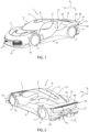
Figure 1 is a front and schematic perspective view, with parts removed for clarity, of a road vehicle realised according to the dictates of the present invention; -
Figure 2 is a rear and schematic perspective view, with parts removed for clarity, of the road vehicle ofFigure 1 ; -
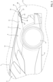
Figure 3 is a side and schematic view, with parts removed for clarity, of a rear side portion of the vehicle ofFigures 1 and 2 , in which a light assembly in accordance with the present invention is visible; -
Figure 4 is a plan view of the light assembly isolated from the vehicle ofFigure 3 ; -
Figure 5 is a side view of the light assembly ofFigure 4 ; -
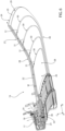
Figure 6 is a perspective and sectional view of the light assembly ofFigures 4 and 5 ; and -
Figure 7 shows a detail ofFigure 6 . - In
Figures 1 and 2 , thenumber 1 denotes, in its entirety, a road vehicle comprising twofront wheels 2 and tworear wheels 3 and comprising anouter body 4 and apassenger compartment 5, obtained inside theouter body 4 between the front andrear wheels - The same reference numbers and reference letters in the figures identify the same elements or components with the same function.
- In this description, the term "second" component does not imply the presence of a "first" component. Such terms are, in fact, adopted as labels to improve clarity and should not be intended as limiting.
- The elements and features illustrated in the different preferred embodiments, including the drawings, may be combined with each other without deviating from the scope of protection of this application as described below.
- It is specified that, in the description that follows, expressions such as "above", "below", "front", "rear" and similar are used with reference to conditions of normal travel of the
road vehicle 1 along the normal travel direction D. - As shown in the non-limiting embodiment of
Figure 1 , it is also possible to define: - a longitudinal axis X, pertaining to the
automobile 1 and arranged, in use, horizontal and parallel to a normal travel direction D of thevehicle 1; - a transverse axis Y, pertaining to the
automobile 1 and arranged, in use, horizontal and orthogonal to the axis X; and - a vertical axis Y, pertaining to the
automobile 1 and arranged, in use, vertical and orthogonal to the axes X, Y. - The
outer body 4 comprises, among other things, anundercarriage 6, abonnet 7, aroof 8 and awindscreen 9 extending between thebonnet 7 and theroof 8. - In particular, the
undercarriage 6 extends between thefront wheels 2 and therear wheels 3. - The
outer body 4 also comprises twofront sidewalls 10, extending on opposite sides of thebonnet 7, and two oppositerear sidewalls 11, aligned with, and distanced from, the respectivefront sidewalls 10. - The
outer body 4 also comprises arear window 12 and aboot 13. - The
windscreen 9 is coupled below with thebonnet 7 and above with theroof 8 and extends between thefront sidewalls 10. - The
rear window 12 is coupled below with theboot 13 and above with theroof 8. Therear window 12 also extends between therear sidewalls 11. - In particular, the
outer body 4 comprises afront portion 14 and arear portion 15 with respect to a travel direction D of theroad vehicle 1. - The
road vehicle 1 advantageously comprises a (backlit)light assembly 16 mounted on thefront portion 14 and/or on theback portion 15, as shown in the non-limiting embodiments of the appended figures. In particular, thelight assembly 16 is configured to be visible (only) from the outside of theroad vehicle 1, for example from a position behind theroad vehicle 1 in the case of the embodiments of the appended figures. - Advantageously, the
light assembly 16 comprises asupport structure 17 configured to be mounted (therefore coupled, for example by means of fastening members of a known type) on theouter body 4 of theroad vehicle 1, in particular at thefront portion 14 and/or therear portion 15, as shown in the appended figures. - The
support structure 17 extends primarily along a first direction A, which corresponds primarily (coincides) substantially with the transverse axis Y of theroad vehicle 1. The term "correspond primarily" in relation to an axis and to a direction means that there is an angle lower than 45°, in particular lower than 20°, between the two of them. - In addition, the
light assembly 16 comprises anilluminating source unit 18, which is mounted on board thesupport structure 17 and comprises a plurality ofluminous devices 19 arranged mainly along the first direction A (i.e. along the transverse axis Y) . - Advantageously but not necessarily, the
luminous devices 19 are astrip 20 of light-emitting diodes 21 (LED). In this manner, it is easily possible to adjust the intensity, the colour and possibly also the frequency of the light radiation emitted by theunit 18. - Advantageously, the
light assembly 16 also comprises an at least partially, in particular totally, transparentpolymeric substrate 22. - Preferably but not in a limiting manner, the
polymeric substrate 22 has a flat shape, i.e. extending primarily in two directions and having a limited thickness W. - In particular, but not in a limiting manner, the thickness W of the polymeric substrate (22) is substantially constant. In other words, the thickness W does not vary, or varies in a negligible manner (for example, of the order of one millimetre), along both or only one of the two extension directions.
- In detail, the
polymeric substrate 22 extends along a second direction B perpendicular to the first direction A and corresponding primarily (coinciding substantially) with the longitudinal axis X of theroad vehicle 1, between aproximal end 23, mounted at thesupport structure 17 and the illuminatingsource unit 18, and adistal end 24, opposite theproximal end 23 and projecting from thesupport structure 17. - Advantageously, but not in a limiting manner, the thickness W of the
polymeric substrate 22 is constant along the direction B, between theproximal end 23 and thedistal end 24. According to several variants, the thickness W varies, in particular increases, from theproximal end 23 to thedistal end 24. - In particular, but not in a limiting manner, the
distal end 24 exits in a cantilevered manner (preferably behind, as shown inFigure 3 ) from theouter body 4 of theroad vehicle 1. In other words, thedistal end 24 projects from the inside to the outside of thevehicle 1. More in particular, thedistal end 24 is exposed outside of thevehicle 1, i.e. directly visible from the outside, without protection means and/or covering members, such as glass, lenses or further polymeric substrates. - As previously mentioned, therefore, the
polymeric substrate 22 comprises a thickness W lower than the other dimensions (along directions A and B) and is configured to be traversed, along its thickness W, by a light beam L emitted by theluminous devices 19 at theproximal end 23, which exits at least from anoutlet profile 25 arranged at thedistal end 24. - In other words, the light beam L emitted by the
diodes 21 traverses thepolymeric substrate 22 primarily (substantially) along the longitudinal axis X of the road vehicle 1 (i.e. along the first direction A). - Preferably, but not in a limiting manner, the
substrate 22 determines a rear spoiler of the road vehicle 1 (i.e. having aerodynamic and/or aesthetic functions). - In the non-limiting embodiment of the appended figures, the
main outlet profile 25 is substantially the end profile of thepolymeric substrate 22. In particular, theoutlet profile 25 is substantially parallel to the vertical axis Z. In this manner, the visibility of the beam L exiting from it is maximised, since theprofile 25 causes a clean interruption of thesubstrate 22. - Advantageously, but not in a limiting manner, the
polymeric substrate 22 is made (at least in part, in particular entirely) of methacrylate (PMMA). In detail, said material may be very transparent (even more than glass) and possesses characteristics of behaviour similar to optical fibre in quality of transparency. In this manner, the light beam L emitted by thediodes 21 may traverse almost completely, and in any case efficiently, thesubstrate 22 until it exits from theprofile 25. - In addition, methacrylate also possesses important mechanical characteristics that make it difficult to break, increasing the safety in the case of impacts (no shards would fly) and simplifying its replacement in safety.
- As shown in the non-limiting embodiment of
Figure 3 , thelight assembly 16 is mounted on therear portion 15, so as to be slightly inclined with respect to the longitudinal axis X of theroad vehicle 1. - Preferably but not in a limiting manner, and as shown clearly in
Figures 5 and6 , thepolymeric substrate 22 comprises, along the second direction B (i.e. along the axis X), starting from theproximal end 23 toward thedistal end 24, afirst portion 26 and asecond portion 27, wherein thesecond portion 27 is inclined, in particular upwardly, with respect to thefirst portion 26. In this manner, the surface ofsubstrate 22 visible for a vehicle following theroad vehicle 1 is increased. - Advantageously, in accordance with what is described above, the
polymeric substrate 22 comprises two mainouter surfaces 28 facing each other and a minorlateral surface 29 connecting the two main outer surfaces 28. Theoutlet profile 25 is at least part of the minorlateral surface 29. - Preferably but not in a limiting manner, the two
main surfaces 28 are striped surfaces, in particular, extendible. - Advantageously, furthermore, according to what is shown by
Figures 4 and6 , thepolymeric substrate 22 comprises, between theproximal end 23 and thedistal end 24, further outlet profiles 30 obtained on at least one of the main outer surfaces 28. - In particular, in the non-limiting embodiment shown, the further outlet profiles 30 are obtained on the main
lower surface 28, so as to be better visible from the rear of theroad vehicle 1. The combination of themain outlet profile 25 with the further outlet profiles 30 allows the light emission exiting from thesubstrate 22 to be thickened, making the vehicle more visible and recognisable, even at long distances. - The further outlet profiles 30 represent interruptions in the continuity of thickness W of the
polymeric substrate 22 and cause the exit of part of the light beam L precisely at these discontinuities, according to known principles of light refraction in a transparent body. - Advantageously, the further outlet profiles 30 are
grooves 31, in particular millings that partially interrupt the passage of the light beam L towards theoutlet profile 25, determining an intermediate partial exit thereof. - Advantageously, but not in a limiting manner, the
grooves 31 determine the interruption of one profile of the at least one mainouter surfaces 28 that otherwise would be continuous, i.e. that excepted where the grooves are is continuous. According to the non-limiting embodiment shown, thegrooves 31 are obtained on the mainlower surface 28 and interrupt its profile. - As shown in the non-limiting embodiments of
Figures 4 and6 , the further outlet profiles 30 are concentric to each other, namely have the same shape, but different dimensions, as theoutlet profile 25, thus of at least part of thelateral surface 29. In particular, theprofiles 30 are symmetric figures with respect to the same centre of symmetry. More in particular, as shown inFigure 4 , theprofiles 30 are substantially projections of theprofile 25 on the plane AB, scaled dimensionally and homogeneously on both axes A and B with respect to the same point of reference. In this manner, the view at a distance of theroad vehicle 1 has a homogeneous form (and achieves the effect of thickening the light emission of only the outlet profile 25). - Preferably but not in a limiting manner, the
outlet profile 25 comprises at least two rectilinear portions parallel to a direction of travel of theroad vehicle 1 and at least one curved portion, wherein the at least one curved portion unites the rectilinear portions. In other words, the rectilinear portions extend mainly along the direction of travel. - In particular, in the non-limiting embodiment of
Figure 4 , theprofile 25 comprises two rectilinear portions substantially parallel to the direction B. More in particular, the rectilinear portions have a component along the axis B and a component along the axis A, and the component along axis B is, preferably, considerably (more than double), larger than the component along axis A. - Advantageously, but not in a limiting manner, the illuminating source unit is integrated into the
support structure 17. Therefore, theluminous devices 19 are not directly visible from the outside of theroad vehicle 1. In this manner, according to what is described here, it is possible to obtain different luminous effects by exploiting the refraction internal to thepolymeric substrate 22, which have no design constraints in relation to the direct view of thediodes 21, which are also more protected. - According to several non-limiting embodiments, such as the one shown in
Figures 6 and7 , at theproximal end 23, theluminous devices 19 emit the light beam L into thepolymeric substrate 22 through aninput surface 32 facing and parallel to theluminous devices 19. More in particular, itsinput surface 32 is substantially planar and parallel to the first direction A and to the second direction B. In other words, theinput surface 32 is primarily horizontal. - Advantageously, but not in a limiting manner, therefore, the
luminous devices 19 are arranged so as to emit the light beam L transversely, in particular perpendicularly, to theinput surface 32 and therefore to the first direction A and to the second direction B. - Preferably, but not in a limiting manner, the
polymeric substrate 22 comprises a slopedreflective surface 33, which is arranged close to the illuminatingsource unit 18, downstream of theinput surface 32, following the path of the light beam L. - The sloped
reflective surface 33 is arranged to deflect the light beam L substantially parallel to the second direction B and therefore, in use, mainly along the longitudinal axis X of the road vehicle 1 (behind, according to the example shown). - Advantageously, but not in a limiting manner, with the exception of the output profiles 25 and 30, the thickness W of the
polymeric substrate 22 after the slopedreflective surface 33 is substantially constant. In this manner, its propagation is optimised. - In the non-limiting embodiment visible in the appended figures, in particular in
Figures 6 and7 , thesupport structure 19 comprises a cavity 34 (elongated) in which both the illuminatingsource unit 18 and theproximal end 23 of thepolymeric substrate 22 are housed. In particular, thecavity 34 extends primarily along the first direction A, i.e. along the transverse axis Y of theroad vehicle 1. - Preferably but not in a limiting manner, and as shown in the embodiments of
Figures 6 and7 , thecavity 34 is bounded, along the second direction B, by afirst containment member 35 , in particular afirst ribbing 36, and asecond containment member 37, in particular asecond ribbing 38, which are preferably made of a piece with thepolymeric substrate 22 and are mounted, by shape coupling, so as to bind thepolymeric substrate 22 to thesupport structure 17. In other words, theribbings polymeric substrate 22 so as to bind it to thesupport structure 17, avoiding a relative movement thereof along the second direction B. - According to several preferred embodiments, therefore, the
light assembly 16 is mounted on theouter body 4 so that thepolymeric substrate 22 vents upwardly. - Preferably but not in a limiting manner, the
polymeric substrate 22 extends transversely from at least aright sidewall 10, 11 (front or rear, as shown) to aleft sidewall 10, 11 (front or rear, as shown) of theroad vehicle 1. - In particular, as shown in
Figures 1 to 3 , thesubstrate 22 comprises aninner portion 39 inside theouter body 4 of theroad vehicle 1, in particular inside thesupport structure 17, and a projectingportion 40, i.e. that part which protrudes from theouter body 4, meaning the vehicle shell, and is visible from the outside of the vehicle, also from above (as shown inFigure 4 ) . - In particular, the projecting
portion 40 comprises in turn arear part 41, which extends substantially along the first direction A and is arranged behind the vehicle, in detail below therear window 12 or thewindscreen 9. - Furthermore, preferably but not in a limiting manner, the projecting
portion 40 comprises a pair ofside parts 42, opposite each other and arranged at thesidewalls side parts 42 project from thesidewalls polymeric substrate 22 is also improved for vehicles that are located laterally with respect to theroad vehicle 1. - Preferably but not in a limiting manner, the
outlet profile 25 and/or the further outlet profiles 30 comprise a surface finish, for example translucent. - In use, the light beam L is emitted by the
diodes 21 downwards, hits and is refracted by the slopedsurface 33 and is propagated as far as theoutlet profile 25, which is illuminated by the interruption of the propagation, as known, in refraction phenomena. A part of the light beam L is, on the other hand, dispersed into the further outlet profiles 30, which in turn will be illuminated by the portion of the light beam L that exits from thepolymeric substrate 22. - Although the invention described here above makes particular reference to a precise example of embodiment, it is not to be considered as limited to said example of embodiment, its scope including all those variants, changes or simplifications covered by the appended claims, such as, for example, a different conformation of the polymeric substrate, a use of the light assembly as headlights, a different type of vehicle.
- From an examination of the features of the
road vehicle 1 and thelight assembly 16 realised according to the present invention, the advantages they allow to achieve are evident. - In particular, in the solution presented here, mounting of the light assembly is simplified and its resistance is improved by protecting the LED strip and exposing exclusively the polymeric substrate to impacts.
- Furthermore, the plurality of outlet profiles determines a thickening of the luminous strip visible from outside the road vehicle.
- In addition, it appears evident that the use of a single strip of diodes to generate a plurality of luminous lines allows the overall weight of the road vehicle to be reduced, with respect to a solution with more strips of diodes, the relative power supplies and the relative cabling.
- Lastly, the freedom of design is improved, as there is no longer a need to position the strip of diodes so that it is directly visible from the outside the vehicle. In this manner, it is possible to produce even complex luminous profiles, which can improve the visibility and recognisability of the road vehicle (including laterally).
-
- 1
- road vehicle
- 2
- front wheels
- 3
- rear wheels
- 4
- outer body
- 5
- passenger compartment
- 6
- undercarriage
- 7
- bonnet
- 8
- roof
- 9
- windscreen
- 10
- front sidewalls
- 11
- rear sidewalls
- 12
- rear window
- 13
- boot
- 14
- front portion
- 15
- rear portion
- 16
- light assembly
- 17
- support structure
- 18
- illuminating source unit
- 19
- luminous devices
- 20
- strip
- 21
- diodes
- 22
- polymeric substrate
- 23
- proximal end
- 24
- distal end
- 25
- outlet profile
- 26
- first portion
- 27
- second portion
- 28
- main surfaces
- 29
- lateral surface
- 30
- further outlet profiles
- 31
- grooves
- 32
- input surface
- 33
- sloped reflective surface
- 34
- cavity
- 35
- first containment member
- 36
- first ribbing
- 37
- second containment member
- 38
- second ribbing
- 39
- inner portion
- 40
- projecting portion
- 41
- rear part
- 42
- lateral parts
- A
- first direction
- B
- second direction
- C
- third direction
- D
- travel direction
- L
- light beam
- W
- thickness
- X
- longitudinal axis
- Y
- transverse axis
- Z
- vertical axis
Claims (16)
- Light assembly (16) for a road vehicle (1); the light assembly (16) comprising:- a support structure (17) configured to be mounted on an outer body (4) of the road vehicle (1) and extending primarily along a first direction (A);- an illuminating source unit (18), mounted on board the support structure (17) and comprising a plurality of luminous devices (19) arranged mainly along the first direction (A); and- an at least partially transparent polymeric substrate (22) extending, along a second direction (B) perpendicular to the first direction (A), between a proximal end (23), mounted at the support structure (17) and the illuminating source unit (18), and a distal end (24), opposite the proximal end (23) and projecting from the support structure (17);wherein the polymeric substrate (22) comprises a thickness (W) lower than the other dimensions and is configured to be traversed, along its thickness (W), by a light beam (L) emitted from the luminous devices (19) at the proximal end (23), which exits at least from an outlet profile (25) arranged at the distal end (24);the light assembly (16) being characterised in that the polymeric substrate (22) comprises:- two main outer surfaces (28) facing each other and a minor lateral surface (29) connecting the two main outer surfaces (28) ; wherein the outlet profile (25) is at least part of the minor lateral surface (29); and- further outlet profiles (30) are made on at least one of the main outer surfaces (28), between the proximal end (23) and the distal end (24); wherein the further outlet profiles (30) are grooves (31), in particular millings that partially interrupt the passage of the light beam (L) towards the outlet profile (25) determining an intermediate partial exit thereof.
- Assembly (16) according to claim 1, wherein the polymeric substrate (22) is made of methacrylate.
- Assembly (16) according to claim 1 or 2, wherein the polymeric substrate (22) comprises, along the second direction (B), starting from the proximal end (23) toward the distal end (24), a first portion (26) and a second portion (27), wherein the second portion (27) is inclined, in particular upwardly, with respect to the first portion (26).
- Assembly (16) according to any one of the preceding claims, wherein the grooves (31) cause interruption of a profile of the at least one of the main outer surfaces (28) that would otherwise be continuous.
- Assembly (16) according to any one of the preceding claims, wherein the thickness (W) of the polymeric substrate (22) is substantially constant.
- Assembly (16) according to any one of the preceding claims, wherein the further outlet profiles (30) are concentric to each other, namely have the same shape, but different dimensions, as the outlet profile (25), thus of at least part of the lateral surface (29).
- Assembly (16) according to any one of the preceding claims, wherein the outlet profile (25) comprises at least two rectilinear portions substantially parallel to a direction of travel of the road vehicle (1) and at least one curved portion, wherein the at least one curved portion unites the rectilinear portions.
- Assembly (16) according to any one of the preceding claims, wherein, at the proximal end (23), the luminous devices (19) emit the light beam (L) into the polymeric substrate (22) through an input surface (32) facing and parallel to the luminous devices (19); wherein the input surface (32) is substantially parallel to the first (A) and to the second direction (B).
- Assembly (16) according to claim 8, wherein the luminous devices (19) are arranged to emit the luminous beam (L) transversely, in particular perpendicularly, to the input surface (32).
- Assembly (16) according to any one of the preceding claims, wherein the polymeric substrate (22) comprises a sloped reflective surface (33) arranged to deflect the light beam (L) parallel to the second direction (B) and, in use, mainly along a longitudinal axis (X) of the road vehicle (1).
- Assembly (16) according to any one of the preceding claims, wherein the luminous devices (19) are a strip (20) of light-emitting diodes (21).
- Assembly (16) according to any one of the preceding claims, wherein the support structure (17) comprises a cavity (34) in which both the illuminating source unit (18) and the proximal end (23) of the polymeric substrate (22) are housed, the cavity (34) extending primarily along the first direction (A).
- Assembly (16) according to claim 12, wherein the cavity (34) is bounded, along the second direction (B), by a first containment member (35) and a second containment member (37), which are made of a piece with the polymeric substrate (22) and are mounted, by shape coupling, so as to bind the polymeric substrate (22) to the support structure (17).
- Road vehicle (1) comprising:- a pair of front wheels (2) and a pair of rear wheels (3);- an outer body (4) comprising a front portion (14) and a rear portion (15) with respect to a normal travel direction (D) of the road vehicle (1); anda light assembly (16) according to any one of the preceding claims, wherein the light assembly (16) is mounted to the front portion (14) and/or the rear portion (15) and is configured to be visible from the outside of the road vehicle (1);wherein a longitudinal axis (X) of the road vehicle (1) corresponds primarily with the second direction (B) and a transverse axis (Y) of the road vehicle (1) corresponds primarily with the first direction (A).
- Road vehicle (1) according to claim 14, wherein the light assembly (16) is mounted to the outer body (4) so that the polymeric substrate (22) vents upwardly.
- Road vehicle (1) according to claim 14 or 15, wherein the polymeric substrate (22) extends transversely from at least a right sidewall to a left sidewall of the road vehicle (1).
Applications Claiming Priority (1)
| Application Number | Priority Date | Filing Date | Title |
|---|---|---|---|
| IT202300014139 | 2023-07-06 |
Publications (1)
| Publication Number | Publication Date |
|---|---|
| EP4488119A1 true EP4488119A1 (en) | 2025-01-08 |
Family
ID=88207257
Family Applications (1)
| Application Number | Title | Priority Date | Filing Date |
|---|---|---|---|
| EP24185637.6A Pending EP4488119A1 (en) | 2023-07-06 | 2024-07-01 | Backlit light assembly for a road vehicle and related road vehicle |
Country Status (2)
| Country | Link |
|---|---|
| US (1) | US12392471B2 (en) |
| EP (1) | EP4488119A1 (en) |
Families Citing this family (2)
| Publication number | Priority date | Publication date | Assignee | Title |
|---|---|---|---|---|
| USD1002467S1 (en) * | 2021-11-12 | 2023-10-24 | Ferrari S.P.A. | Interior for a vehicle |
| USD1120413S1 (en) * | 2023-06-12 | 2026-03-24 | Ferrari S.P.A. | Light for vehicles |
Citations (18)
| Publication number | Priority date | Publication date | Assignee | Title |
|---|---|---|---|---|
| CN201102500Y (en) * | 2007-09-17 | 2008-08-20 | 林伊平 | Automobile spoiler with luminous effect |
| EP2169296A1 (en) * | 2008-09-25 | 2010-03-31 | Valeo Vision | Lighting device comprising a light guide |
| JP2012064535A (en) * | 2010-09-17 | 2012-03-29 | Koito Mfg Co Ltd | Lamp fitting for vehicle |
| JP2014154219A (en) * | 2013-02-05 | 2014-08-25 | Koito Mfg Co Ltd | Vehicular lighting fixture |
| EP2816276A2 (en) * | 2013-06-22 | 2014-12-24 | Volkswagen Aktiengesellschaft | Motor vehicle with a lighting device |
| US20160091653A1 (en) * | 2014-09-29 | 2016-03-31 | Honda Motor Co., Ltd. | Illuminator |
| EP3062015A2 (en) * | 2015-02-26 | 2016-08-31 | Valeo Iluminacion | Light device of a motor vehicle |
| FR3054641A1 (en) * | 2016-07-29 | 2018-02-02 | Valeo Iluminacion | THIRD STOP FIRE WITH OUTPUT OF REDUCED THICKNESS |
| KR20180076708A (en) * | 2016-12-28 | 2018-07-06 | 에스엘 주식회사 | Lamp for vehicle |
| JP2018137127A (en) * | 2017-02-22 | 2018-08-30 | スタンレー電気株式会社 | Vehicular lighting fixture |
| EP3372892A1 (en) * | 2017-03-07 | 2018-09-12 | PSA Automobiles SA | Lighting device with simplified and accurate positioning of the light sources and light guides |
| JP2018198134A (en) * | 2017-05-23 | 2018-12-13 | 市光工業株式会社 | Vehicle lighting |
| DE102018100819A1 (en) * | 2018-01-16 | 2019-07-18 | Dr. Ing. H.C. F. Porsche Aktiengesellschaft | Rear wing with brake light |
| EP3543598A1 (en) * | 2018-03-20 | 2019-09-25 | PSA Automobiles SA | Arrangement for motor vehicle comprising a bodywork element and a lighting and/or signalling device with a light guide installed in said bodywork element |
| JP2020087624A (en) * | 2018-11-21 | 2020-06-04 | スタンレー電気株式会社 | Vehicular lighting fixture |
| EP2635842B1 (en) * | 2010-11-05 | 2020-08-19 | Valeo Vision | Lighting or signalling device for a motor vehicle, comprising a light guide layer |
| FR3097026A1 (en) * | 2019-06-04 | 2020-12-11 | Psa Automobiles Sa | Signal light with two cantilevered light guides. |
| EP3862624A1 (en) * | 2020-02-06 | 2021-08-11 | Marelli Automotive Lighting Italy S.p.A. Con Socio Unico | Lighting device for vehicles, in particular with leds |
Family Cites Families (1)
| Publication number | Priority date | Publication date | Assignee | Title |
|---|---|---|---|---|
| US7052074B2 (en) * | 2003-10-03 | 2006-05-30 | All Sales Manufacturing, Inc. | Angularly adjustable illuminated spoiler |
-
2024
- 2024-07-01 EP EP24185637.6A patent/EP4488119A1/en active Pending
- 2024-07-03 US US18/762,845 patent/US12392471B2/en active Active
Patent Citations (18)
| Publication number | Priority date | Publication date | Assignee | Title |
|---|---|---|---|---|
| CN201102500Y (en) * | 2007-09-17 | 2008-08-20 | 林伊平 | Automobile spoiler with luminous effect |
| EP2169296A1 (en) * | 2008-09-25 | 2010-03-31 | Valeo Vision | Lighting device comprising a light guide |
| JP2012064535A (en) * | 2010-09-17 | 2012-03-29 | Koito Mfg Co Ltd | Lamp fitting for vehicle |
| EP2635842B1 (en) * | 2010-11-05 | 2020-08-19 | Valeo Vision | Lighting or signalling device for a motor vehicle, comprising a light guide layer |
| JP2014154219A (en) * | 2013-02-05 | 2014-08-25 | Koito Mfg Co Ltd | Vehicular lighting fixture |
| EP2816276A2 (en) * | 2013-06-22 | 2014-12-24 | Volkswagen Aktiengesellschaft | Motor vehicle with a lighting device |
| US20160091653A1 (en) * | 2014-09-29 | 2016-03-31 | Honda Motor Co., Ltd. | Illuminator |
| EP3062015A2 (en) * | 2015-02-26 | 2016-08-31 | Valeo Iluminacion | Light device of a motor vehicle |
| FR3054641A1 (en) * | 2016-07-29 | 2018-02-02 | Valeo Iluminacion | THIRD STOP FIRE WITH OUTPUT OF REDUCED THICKNESS |
| KR20180076708A (en) * | 2016-12-28 | 2018-07-06 | 에스엘 주식회사 | Lamp for vehicle |
| JP2018137127A (en) * | 2017-02-22 | 2018-08-30 | スタンレー電気株式会社 | Vehicular lighting fixture |
| EP3372892A1 (en) * | 2017-03-07 | 2018-09-12 | PSA Automobiles SA | Lighting device with simplified and accurate positioning of the light sources and light guides |
| JP2018198134A (en) * | 2017-05-23 | 2018-12-13 | 市光工業株式会社 | Vehicle lighting |
| DE102018100819A1 (en) * | 2018-01-16 | 2019-07-18 | Dr. Ing. H.C. F. Porsche Aktiengesellschaft | Rear wing with brake light |
| EP3543598A1 (en) * | 2018-03-20 | 2019-09-25 | PSA Automobiles SA | Arrangement for motor vehicle comprising a bodywork element and a lighting and/or signalling device with a light guide installed in said bodywork element |
| JP2020087624A (en) * | 2018-11-21 | 2020-06-04 | スタンレー電気株式会社 | Vehicular lighting fixture |
| FR3097026A1 (en) * | 2019-06-04 | 2020-12-11 | Psa Automobiles Sa | Signal light with two cantilevered light guides. |
| EP3862624A1 (en) * | 2020-02-06 | 2021-08-11 | Marelli Automotive Lighting Italy S.p.A. Con Socio Unico | Lighting device for vehicles, in particular with leds |
Also Published As
| Publication number | Publication date |
|---|---|
| US12392471B2 (en) | 2025-08-19 |
| US20250052399A1 (en) | 2025-02-13 |
Similar Documents
| Publication | Publication Date | Title |
|---|---|---|
| EP4488119A1 (en) | Backlit light assembly for a road vehicle and related road vehicle | |
| EP2548769B1 (en) | Automotive rear light | |
| EP2157363B1 (en) | Optical element for vehicle lamp | |
| KR20130044341A (en) | Signalling lamps for motor vehicle | |
| US9169987B2 (en) | Lighting appliance for vehicles | |
| EP3988840B1 (en) | Vehicle lamp | |
| CN103867983B (en) | Motor vehicles back light | |
| US11746984B2 (en) | Illumination device for vehicles | |
| EP2731824A1 (en) | Automotive light | |
| CN115539889A (en) | Exterior light assembly for vehicle and method of using same | |
| US12240374B2 (en) | Automotive light | |
| KR20220024739A (en) | Optical element, vehicle lamp module, vehicle lamp and vehicle | |
| US6471380B1 (en) | Blink lamp for vehicles | |
| WO2023072988A1 (en) | Light guide blade for a motor vehicle | |
| CN217294376U (en) | Vehicle lamp | |
| EP4419836B1 (en) | Light guide for a vehicle lamp assembly | |
| WO2024034558A1 (en) | Vehicle lamp | |
| US11300265B2 (en) | Lamp for automobile and automobile including the same | |
| CN118009273A (en) | Lighting device for motor vehicle | |
| US12607317B2 (en) | Running light for a vehicle | |
| CN219995142U (en) | Light guide assembly, lamp device and motor vehicle | |
| US20260117950A1 (en) | Lighting device for a motor vehicle and motor vehicle having such a lighting device | |
| WO2025003529A1 (en) | Optical component, lighting device and vehicle | |
| CN219995137U (en) | Light guide device, lamp assembly and motor vehicle | |
| KR102736462B1 (en) | Lamp assembly for vehicle |
Legal Events
| Date | Code | Title | Description |
|---|---|---|---|
| PUAI | Public reference made under article 153(3) epc to a published international application that has entered the european phase |
Free format text: ORIGINAL CODE: 0009012 |
|
| STAA | Information on the status of an ep patent application or granted ep patent |
Free format text: STATUS: THE APPLICATION HAS BEEN PUBLISHED |
|
| AK | Designated contracting states |
Kind code of ref document: A1 Designated state(s): AL AT BE BG CH CY CZ DE DK EE ES FI FR GB GR HR HU IE IS IT LI LT LU LV MC ME MK MT NL NO PL PT RO RS SE SI SK SM TR |
|
| STAA | Information on the status of an ep patent application or granted ep patent |
Free format text: STATUS: REQUEST FOR EXAMINATION WAS MADE |
|
| 17P | Request for examination filed |
Effective date: 20250708 |
|
| STAA | Information on the status of an ep patent application or granted ep patent |
Free format text: STATUS: EXAMINATION IS IN PROGRESS |
|
| 17Q | First examination report despatched |
Effective date: 20260123 |