EP4488080A2 - A tool - Google Patents
A tool Download PDFInfo
- Publication number
- EP4488080A2 EP4488080A2 EP24215847.5A EP24215847A EP4488080A2 EP 4488080 A2 EP4488080 A2 EP 4488080A2 EP 24215847 A EP24215847 A EP 24215847A EP 4488080 A2 EP4488080 A2 EP 4488080A2
- Authority
- EP
- European Patent Office
- Prior art keywords
- tyre
- wing
- wheel rim
- tool
- side wall
- Prior art date
- Legal status (The legal status is an assumption and is not a legal conclusion. Google has not performed a legal analysis and makes no representation as to the accuracy of the status listed.)
- Pending
Links
Images


Classifications
-
- B—PERFORMING OPERATIONS; TRANSPORTING
- B60—VEHICLES IN GENERAL
- B60C—VEHICLE TYRES; TYRE INFLATION; TYRE CHANGING; CONNECTING VALVES TO INFLATABLE ELASTIC BODIES IN GENERAL; DEVICES OR ARRANGEMENTS RELATED TO TYRES
- B60C25/00—Apparatus or tools adapted for mounting, removing or inspecting tyres
- B60C25/01—Apparatus or tools adapted for mounting, removing or inspecting tyres for removing tyres from or mounting tyres on wheels
-
- B—PERFORMING OPERATIONS; TRANSPORTING
- B60—VEHICLES IN GENERAL
- B60C—VEHICLE TYRES; TYRE INFLATION; TYRE CHANGING; CONNECTING VALVES TO INFLATABLE ELASTIC BODIES IN GENERAL; DEVICES OR ARRANGEMENTS RELATED TO TYRES
- B60C25/00—Apparatus or tools adapted for mounting, removing or inspecting tyres
- B60C25/01—Apparatus or tools adapted for mounting, removing or inspecting tyres for removing tyres from or mounting tyres on wheels
- B60C25/02—Tyre levers or the like, e.g. hand-held
-
- B—PERFORMING OPERATIONS; TRANSPORTING
- B60—VEHICLES IN GENERAL
- B60C—VEHICLE TYRES; TYRE INFLATION; TYRE CHANGING; CONNECTING VALVES TO INFLATABLE ELASTIC BODIES IN GENERAL; DEVICES OR ARRANGEMENTS RELATED TO TYRES
- B60C25/00—Apparatus or tools adapted for mounting, removing or inspecting tyres
- B60C25/01—Apparatus or tools adapted for mounting, removing or inspecting tyres for removing tyres from or mounting tyres on wheels
- B60C25/02—Tyre levers or the like, e.g. hand-held
- B60C25/04—Tyre levers or the like, e.g. hand-held pivotal about the wheel axis, or movable along the rim edge, e.g. rollable
Definitions
- the present invention relates to tools for installing bicycle tyres on bicycle wheel rims and/or removing bicycle tyres from bicycle wheel rims.
- a tyre lever may be used to ease the tyre over the side wall of wheel rim.
- the lever may be placed between a wheel rim and tyre bead in use, with pressure being applied to the tyre lever to lift the corresponding section of the tyre bead and tyre wall away from the wheel rim; an example is disclosed in WO9813221 .
- US9656524 discloses a further example of a tyre lever for removing and installing bicycle tyres.
- the tyre lever comprises a first hook for removing a tyre and a second hook for installing a tyre.
- the tool may be moved circumferentially around the wheel rim in use, with the length of the tool being orientated generally radially with respect to the wheel.
- US2018/290508A1 discloses a tyre assembling device which includes a main body, a holding portion, an abutting surface, a guiding portion, a pressing portion and a protrusion.
- the main body has a top surface.
- the holding portion is connected to one side of the main body.
- the abutting surface is connected to another side of the main body is for abutting against a rim surface of the rim.
- the guiding portion located between the abutting surface and the top surface is extended inclinedly corresponding to a radial direction of the rim.
- the pressing portion extended from the guiding portion toward a reference direction is protruded from the abutting surface and connected to the top surface.
- the protrusion protruded from the pressing portion forms a hook portion with an upper edge of the pressing portion and the abutting surface.
- the hook portion is for hooking a first edge of the rim.
- US2013/192767A1 discloses a unitary structure tyre lever which has an opening for a user to insert fingers and grab the lever when installing and removing a tyre from a rim.
- the lever has a curved smooth installation hook at one end with a ridge to engage a lip of a tyre rim during tyre installation.
- the lever also has a curved smooth removal hook at the other end with a notch that enables the lever to pivot about the lip of the tyre rim during tyre removal.
- the removal hook also has a curved seat portion that engages with a bead of the tyre during tyre removal.
- Known bicycle tyre levers are generally elongate, with the length of the tyre lever extending radially towards the centre of the bicycle wheel in use.
- Such levers comprise a relatively narrow hook or lever section which is positioned between a tyre and a wheel rim in use. Where a tyre is fitted tightly on a wheel rim, it may be necessary to use a series of tyre levers to ease the tyre onto or away from the wheel rim.
- a tyre lever is narrow, the pressure exerted on or by the tyre lever when it is located between the tyre and the wheel rim may make it difficult to move the tyre lever circumferentially around the wheel rim to ease the tyre either onto or away from the wheel rim, and in some cases may result in damage to the wheel rim.
- a tool for installing a tyre on a wheel rim comprising:
- a radius of curvature of the upper side of the wing about the axis may increase from the leading edge toward a trailing edge of the wing.
- the tool may further comprise guiding means disposed upon the upper portion of the body for guiding the side wall of the tyre upon the wing.
- the guiding means may be disposed along the body between the wing and the forward portion of the body.
- the guiding means may comprise a ramped protuberance formed upon the upper portion for lifting the side wall of the tyre upon the wing.
- the tool may further comprise an abutment surface for engaging with the side wall of the tyre and deflecting the side wall of the tyre upon the upper side of the wing.
- the abutment surface may comprise a quarter sphere.
- the tool may comprise a flange for removal of a tyre from a wheel rim.
- the flange may extend from the side of the body opposite the side from which the wing extends.
- the flange may be located proximate the rearward portion of the body.
- the flange may extend between the upper portion and a lower portion of the body and may extend substantially perpendicularly to the body.
- the width of the flange may be 20-60mm, preferably 30-50mm or more preferably 40-50mm.
- a tool for removal or a tyre from a wheel rim comprising a body and a flange extending from a side of the body and extending substantially perpendicularly to the body.
- the width of the flange may be 20-60mm, preferably 30-50mm or more preferably 40-50mm.
- FIG. 1-10 there is shown a tool according to an embodiment of the present invention.
- the tool 100 comprises a body 1 comprising a first side 10, a second side 20, a forward portion 30, a rearward portion 40, an upper portion 50 and a lower portion 60, in use.
- the tool 100 may be made from any material of suitable strength, for example plastics material or metal.
- the body 1 is generally elongate, and the first side 10 comprises a planar face 11.
- the length of the body 1 extends between the forward portion 30 and the rearward portion 40, and the upper portion 50 and lower portion 60 of the body 1 converge towards the forward portion 30.
- a first part 12a of the wing 12 extends outwardly from the first side 10 and a second part 12b of the wing 12 extends from the first part 12a in a direction which is substantially parallel with the planar face 11 of the body 1, thereby forming an overhang.
- the wing 12 and a section of the planar face 11 form a substantially U-shaped open channel 13, as shown in Figures 8 and 9 .
- the inner surface of the wing 12 comprises a lip 12c, which extends towards the planar face 11.
- the lip 12c extends at least partially along the length of the inner surface of the wing 12 in a direction extending between the forward portion 30 and the rearward portion 40.
- the wing 12 has a leading edge 15 which is proximal to the forward portion 30 of the body 1, as shown in Figures 1 and 7 .
- a trailing edge 16 of the wing 12 is proximal to the rearward portion 40 of the body 1, as shown in Figures 1 and 8 .
- the outer surface 14 of the wing 12 is curved as it extends between the leading edge 15 and the trailing edge 16, as shown in Figure 3 .
- the leading edge 15 of the wing 12 is swept toward the rearward portion of the body, as shown in Figure 5 .
- An inner surface portion 13a which forms part of the channel 13, may also be curved between the leading edge 15 and trailing edge 16 of the wing 12 with a radius of curvature similar to or the same as that of the circumference of the wheel rim.
- the inner surface portion 13a may comprise one linear surface or a series of linear surfaces extending between the leading edge 15 and the trailing edge 16.
- the outer surface 14 of the wing 12 is also curved as it extends outwardly from the first side 10 to form a convex surface about an axis which is parallel to an axis extending between the leading edge 15 and the trailing edge 16, as illustrated in Figures 1 , 7 and 8 .
- the axis about which the surface is curved may extend substantially along the channel.
- This radius of curvature of the convex profile of the surface of the outer surface 14 at the leading edge 15 (as shown in Figure 7 ) is smaller than the radius of curvature of the convex profile at the trailing edge 16 (as shown in Figure 8 ).
- the radius of curvature gradually increases from the leading edge 15 to trailing edge 16.
- the guiding means 17 Adjacent to the wing 12 is the guiding means 17, which extends from an upper surface 51 of the body 1 in use.
- the guiding means 17 is tapered in the direction of the forward portion 30 and in the direction of the rearward portion 40 also, forming a ramped protuberance upon the upper portion 50 of the body 1.
- the guiding means has a curved surface.
- the guiding means 17 is for guiding the side wall of the tyre towards the wheel rim and onto the wing 12 in use.
- the abutment surface 18 is for guiding a tyre towards the wheel rim and aligning the tyre with the wing 12 in use.
- the abutment surface 18 comprises a quarter sphere, although it will be understood that any shaped surface which is capable of guiding a tyre towards the wheel rim and aligning the tyre with the wing 12 may be used.
- the second side 20 of the body comprises a holding region for holding by a user.
- the holding region may be used to manipulate the tool 100 in use.
- the holding region comprises both the upper surface 51 of the body 1 and an end section 41 proximate the rearward portion 40 of the body 1.
- the end section 41 extends substantially perpendicularly to the upper surface.
- the end section 41 also comprises a flange 41a, the width of which extends along the full length of the end section 41.
- the flange 41a extends from the second side 20 of the body 1.
- the flange 41a may extend substantially perpendicularly from the second side 20 of the body 1, and/or may form an acute angle with the second side 20, which may be greater than 45 degrees.
- the acute angle is greater than 50 degrees, preferably greater than 60 degrees and more preferably greater than 70 degrees.
- the width of the flange 41a is 20-60mm, preferably 30-50mm and more preferably 40-50mm.
- a user When installing a tyre on a wheel rim a user can usually, without the use of a tool, lift a tyre over a wheel rim wall so that a first side wall of the tyre is wholly seated in the channel of the wheel rim. A section of the second side wall of the tyre may also be lifted over the wheel rim fairly easily and without the use of a tool so that the tyre second side wall is partially installed on the wheel rim.
- it can be difficult if not impossible to lift the remainder of the second side wall over the wheel rim wall without the use of the tool because of the tight fit of the tyre and/or its inflexibility.
- the tool 100 may then be used to lift the bead of the second side wall and corresponding section of the tyre side wall over the wheel rim so that the entirety of the tyre second side wall may be seated in the channel of the wheel rim.
- the user orientates the tool 100 so that the first side 10 of the body 1 faces the tyre and the wheel rim, and the second part 12b of the wing 12 extends towards the centre of the wheel.
- the user inserts the second part 12b between the wheel rim and the tyre second side wall which is already seated in the channel of the wheel rim.
- the corresponding portion of the wheel rim side wall is therefore located in the channel 13 of the tool 100.
- the user moves the tool around the wheel rim circumferentially, while maintaining the wheel rim side wall in the channel 13.
- the user pushes on the end section 41 to move the tool 100 circumferentially relative to the wheel rim in a clockwise direction (when viewed from the second side 20) towards the section of the tyre second side wall which is not yet installed on the wheel.
- the user pushes the flange 41a underneath part of the tyre bead on one of the side walls of the tyre so that the tyre bead is lifted and the flange 41a is located between the tyre bead and the wheel rim.
- the flange 41a is therefore located behind the tyre side wall.
- the user orientates the tool so that the end section 41 is substantially parallel with the corresponding part of the wheel rim outer wall, and in doing so further lifts the tyre bead over and away from the wheel rim, as shown in Figure 10 .
- the tool may then be moved circumferentially around the wheel rim until all of the tyre side wall has been removed from the wheel rim, or until enough of the tyre side wall has been removed for a user to continue to remove the tyre without the use of the tool.
- the tool may be moved circumferentially in either rotational direction to achieve this.
- These features may provide the advantage of spreading the force exerted by the tool 100 across a larger surface area of the wheel rim and avoiding putting undue pressure on the outermost edge of the wheel rim, thereby making it easier to move the tool 100 circumferentially around the wheel rim in use and avoiding damage to wheel rim.
- a user may choose to remove the remainder of the tyre from the wheel rim without using the tool.
- the tool may comprise only the features required for installing the tyre or only the features required for removing the tyre.
Landscapes
- Engineering & Computer Science (AREA)
- Mechanical Engineering (AREA)
- Tires In General (AREA)
- Turbine Rotor Nozzle Sealing (AREA)
Abstract
Description
- The present invention relates to tools for installing bicycle tyres on bicycle wheel rims and/or removing bicycle tyres from bicycle wheel rims.
- Installing bicycle tyres on and removing bicycle tyres from wheel rims is an essential aspect of bicycle maintenance and repair. Depending on the type of tyre and wheel rim utilised, the ease with which a tyre can be installed on or removed from the wheel rim can vary greatly depending on how tightly the tyre fits on the wheel rim. Where a tyre is, or is to be, mounted tightly on a wheel rim, it may be necessary to employ a tool, such as a tyre lever, to aid a user in lifting the tyre bead and corresponding section of the tyre side wall over the wheel rim during installation or removal of the tyre.
- It is very well known to use a tyre lever to facilitate the installation of a tyre on a wheel rim and to allow the removal of a tyre from a wheel rim. When installing the tyre, a tyre lever may be used to ease the tyre over the side wall of wheel rim. During removal of the tyre, the lever may be placed between a wheel rim and tyre bead in use, with pressure being applied to the tyre lever to lift the corresponding section of the tyre bead and tyre wall away from the wheel rim; an example is disclosed in
WO9813221 -
US9656524 -
US2018/290508A1 discloses a tyre assembling device which includes a main body, a holding portion, an abutting surface, a guiding portion, a pressing portion and a protrusion. The main body has a top surface. The holding portion is connected to one side of the main body. The abutting surface is connected to another side of the main body is for abutting against a rim surface of the rim. The guiding portion located between the abutting surface and the top surface is extended inclinedly corresponding to a radial direction of the rim. The pressing portion extended from the guiding portion toward a reference direction is protruded from the abutting surface and connected to the top surface. The protrusion protruded from the pressing portion forms a hook portion with an upper edge of the pressing portion and the abutting surface. The hook portion is for hooking a first edge of the rim. -
US2013/192767A1 discloses a unitary structure tyre lever which has an opening for a user to insert fingers and grab the lever when installing and removing a tyre from a rim. The lever has a curved smooth installation hook at one end with a ridge to engage a lip of a tyre rim during tyre installation. The lever also has a curved smooth removal hook at the other end with a notch that enables the lever to pivot about the lip of the tyre rim during tyre removal. The removal hook also has a curved seat portion that engages with a bead of the tyre during tyre removal. -
US7556078B1 discloses a tool for completing the mounting of a bicycle tyre onto its rim. The use of a tool is usually required to complete the job of mounting a bicycle tyre to its rim due to the high tension developed in the bead of the tyre at that stage. The tool employs a traveling inclined plane to progressively lift the tyre bead to a height above an edge of the wheel rim, and a downwardly sloped incline to allow the so lifted bead to then slide down into the rim's interior. The tool utilizes the flange, or rim sidewall, of the wheel rim for both support and guidance as it is impelled forward on the rim by impacts on its trailing surface from an object suitable for the function, such as a hammer. - Known bicycle tyre levers are generally elongate, with the length of the tyre lever extending radially towards the centre of the bicycle wheel in use. Such levers comprise a relatively narrow hook or lever section which is positioned between a tyre and a wheel rim in use. Where a tyre is fitted tightly on a wheel rim, it may be necessary to use a series of tyre levers to ease the tyre onto or away from the wheel rim. If a tyre lever is narrow, the pressure exerted on or by the tyre lever when it is located between the tyre and the wheel rim may make it difficult to move the tyre lever circumferentially around the wheel rim to ease the tyre either onto or away from the wheel rim, and in some cases may result in damage to the wheel rim.
- Accordingly, it is an object of the invention to alleviate the disadvantages of the prior art.
- A tool for installing a tyre on a wheel rim, the tool comprising:
- a body;
- a wing extending from an upper portion of the body to form an overhang over a side of the body, such that the side of the body and an underside of the wing from an open channel for receiving in use an outer peripheral portion of a wall of the wheel rim, the channel extending between a forward portion and a rearward portion of the body;
- the wing comprising a leading edge and an upper side which are arranged to engage in use with a side wall of the tyre;
- A radius of curvature of the upper side of the wing about the axis may increase from the leading edge toward a trailing edge of the wing.
- The tool may further comprise guiding means disposed upon the upper portion of the body for guiding the side wall of the tyre upon the wing.
- The guiding means may be disposed along the body between the wing and the forward portion of the body. The guiding means may comprise a ramped protuberance formed upon the upper portion for lifting the side wall of the tyre upon the wing.
- The tool may further comprise an abutment surface for engaging with the side wall of the tyre and deflecting the side wall of the tyre upon the upper side of the wing. The abutment surface may comprise a quarter sphere.
- The tool may comprise a flange for removal of a tyre from a wheel rim.
- The flange may extend from the side of the body opposite the side from which the wing extends. The flange may be located proximate the rearward portion of the body. The flange may extend between the upper portion and a lower portion of the body and may extend substantially perpendicularly to the body.
- The width of the flange may be 20-60mm, preferably 30-50mm or more preferably 40-50mm.
- In a second aspect of the invention, there is provided a tool for removal or a tyre from a wheel rim, the tool comprising a body and a flange extending from a side of the body and extending substantially perpendicularly to the body.
- The width of the flange may be 20-60mm, preferably 30-50mm or more preferably 40-50mm.
-
-
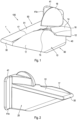
Figure 1 is a first perspective view of a tool according to an embodiment of the present invention. -
Figure 2 is a second perspective view of the tool ofFigure 1 . -
Figure 3 is a view of a first side of the tool ofFigure 1 . -
Figure 4 is a view of a second side of the tool ofFigure 1 . -
Figure 5 is the tool ofFigure 1 as viewed from above. -
Figure 6 is the tool ofFigure 1 as viewed from below. -
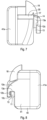
Figure 7 is a side view from the forward portion of the tool ofFigure 1 . -
Figure 8 is a side view from the rearward portion of the tool ofFigure 1 . -
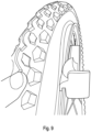
Figure 9 is a back view of the tool ofFigure 1 in use during installation of a tyre on a wheel rim. -
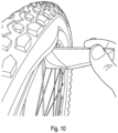
Figure 10 shows the tool ofFigure 1 in use during removal of a tyre from a wheel rim. - Referring to
Figures 1-10 , there is shown a tool according to an embodiment of the present invention. - The
tool 100 comprises a body 1 comprising afirst side 10, asecond side 20, aforward portion 30, arearward portion 40, anupper portion 50 and alower portion 60, in use. Thetool 100 may be made from any material of suitable strength, for example plastics material or metal. - In the illustrated embodiment, the body 1 is generally elongate, and the
first side 10 comprises aplanar face 11. The length of the body 1 extends between theforward portion 30 and therearward portion 40, and theupper portion 50 andlower portion 60 of the body 1 converge towards theforward portion 30. - The
first side 10 of the body 1 comprises awing 12, a guiding means 17 and anabutment surface 18. - As shown in
Figure 8 , afirst part 12a of thewing 12 extends outwardly from thefirst side 10 and asecond part 12b of thewing 12 extends from thefirst part 12a in a direction which is substantially parallel with theplanar face 11 of the body 1, thereby forming an overhang. Thewing 12 and a section of theplanar face 11 form a substantially U-shapedopen channel 13, as shown inFigures 8 and9 . The inner surface of thewing 12 comprises alip 12c, which extends towards theplanar face 11. Thelip 12c extends at least partially along the length of the inner surface of thewing 12 in a direction extending between theforward portion 30 and therearward portion 40. - The
wing 12 has aleading edge 15 which is proximal to theforward portion 30 of the body 1, as shown inFigures 1 and7 . A trailingedge 16 of thewing 12 is proximal to therearward portion 40 of the body 1, as shown inFigures 1 and8 . Theouter surface 14 of thewing 12 is curved as it extends between theleading edge 15 and the trailingedge 16, as shown inFigure 3 . The leadingedge 15 of thewing 12 is swept toward the rearward portion of the body, as shown inFigure 5 . - An
inner surface portion 13a, which forms part of thechannel 13, may also be curved between theleading edge 15 and trailingedge 16 of thewing 12 with a radius of curvature similar to or the same as that of the circumference of the wheel rim. Alternatively, theinner surface portion 13a may comprise one linear surface or a series of linear surfaces extending between theleading edge 15 and the trailingedge 16. - The
outer surface 14 of thewing 12 is also curved as it extends outwardly from thefirst side 10 to form a convex surface about an axis which is parallel to an axis extending between theleading edge 15 and the trailingedge 16, as illustrated inFigures 1 ,7 and 8 . The axis about which the surface is curved may extend substantially along the channel. This radius of curvature of the convex profile of the surface of theouter surface 14 at the leading edge 15 (as shown inFigure 7 ) is smaller than the radius of curvature of the convex profile at the trailing edge 16 (as shown inFigure 8 ). The radius of curvature gradually increases from the leadingedge 15 to trailingedge 16. - While in the illustrated embodiment the
outer surface 14 of thewing 12 is curved, the skilled person will appreciate that other equivalent surface profiles may be used, for example, one of more angled surfaces. - Adjacent to the
wing 12 is the guiding means 17, which extends from anupper surface 51 of the body 1 in use. When viewed from thefirst side 10, the guiding means 17 is tapered in the direction of theforward portion 30 and in the direction of therearward portion 40 also, forming a ramped protuberance upon theupper portion 50 of the body 1. When viewed from above (as shown inFigure 5 ), the guiding means has a curved surface. The guiding means 17 is for guiding the side wall of the tyre towards the wheel rim and onto thewing 12 in use. - The
abutment surface 18 is for guiding a tyre towards the wheel rim and aligning the tyre with thewing 12 in use. In the illustrated embodiment, theabutment surface 18 comprises a quarter sphere, although it will be understood that any shaped surface which is capable of guiding a tyre towards the wheel rim and aligning the tyre with thewing 12 may be used. - The
second side 20 of the body comprises a holding region for holding by a user. The holding region may be used to manipulate thetool 100 in use. In the illustrated embodiment, the holding region comprises both theupper surface 51 of the body 1 and anend section 41 proximate therearward portion 40 of the body 1. Theend section 41 extends substantially perpendicularly to the upper surface. In the illustrated embodiment, theend section 41 also comprises aflange 41a, the width of which extends along the full length of theend section 41. Theflange 41a extends from thesecond side 20 of the body 1. Theflange 41a may extend substantially perpendicularly from thesecond side 20 of the body 1, and/or may form an acute angle with thesecond side 20, which may be greater than 45 degrees. In a preferred embodiment, the acute angle is greater than 50 degrees, preferably greater than 60 degrees and more preferably greater than 70 degrees. In a preferred embodiment, the width of theflange 41a is 20-60mm, preferably 30-50mm and more preferably 40-50mm. - Use of the invention to install and remove a tyre on a wheel rim will now be described with reference to the illustrated embodiment.
- When installing a tyre on a wheel rim a user can usually, without the use of a tool, lift a tyre over a wheel rim wall so that a first side wall of the tyre is wholly seated in the channel of the wheel rim. A section of the second side wall of the tyre may also be lifted over the wheel rim fairly easily and without the use of a tool so that the tyre second side wall is partially installed on the wheel rim. However, once the first side wall and part of the second side wall are installed, it can be difficult if not impossible to lift the remainder of the second side wall over the wheel rim wall without the use of the tool because of the tight fit of the tyre and/or its inflexibility. At this stage, it becomes necessary to employ a tool to install the remainder of the second side wall on the wheel rim.
- Once the second side wall is partially installed on a wheel rim, the
tool 100 may then be used to lift the bead of the second side wall and corresponding section of the tyre side wall over the wheel rim so that the entirety of the tyre second side wall may be seated in the channel of the wheel rim. - To achieve this, the user orientates the
tool 100 so that thefirst side 10 of the body 1 faces the tyre and the wheel rim, and thesecond part 12b of thewing 12 extends towards the centre of the wheel. The user inserts thesecond part 12b between the wheel rim and the tyre second side wall which is already seated in the channel of the wheel rim. The corresponding portion of the wheel rim side wall is therefore located in thechannel 13 of thetool 100. - To install the remainder of the second side wall on the wheel rim, the user moves the tool around the wheel rim circumferentially, while maintaining the wheel rim side wall in the
channel 13. When thetool 100 of the illustrated embodiment is engaged with the wheel rim as described, the user pushes on theend section 41 to move thetool 100 circumferentially relative to the wheel rim in a clockwise direction (when viewed from the second side 20) towards the section of the tyre second side wall which is not yet installed on the wheel. - As the
forward portion 30 engages the uninstalled section of the tyre second side wall, the user continues to move the tool circumferentially so that the guiding means 17 guides the uninstalled section inwardly towards the wheel rim side wall. As the user continues to move the tool circumferentially, the same portion of the uninstalled section engages theabutment surface 18, which further guides the uninstalled section towards the wheel rim and thewing leading edge 15. As the tool continues to move circumferentially around the wheel rim, the tyre bead and side wall of the uninstalled section move over the curvedouter surface 14 of thewing 12 and are thereby eased over the side wall of the wheel rim. The user continues to push thetool 100 circumferentially around the wheel rim to feed the tyre bead and side wall onto the wheel rim until the entirety of the tyre second side wall is installed on the wheel rim, as shown inFigure 9 . - To remove a tyre from a wheel rim, the user pushes the
flange 41a underneath part of the tyre bead on one of the side walls of the tyre so that the tyre bead is lifted and theflange 41a is located between the tyre bead and the wheel rim. In this configuration, theflange 41a is therefore located behind the tyre side wall. The user orientates the tool so that theend section 41 is substantially parallel with the corresponding part of the wheel rim outer wall, and in doing so further lifts the tyre bead over and away from the wheel rim, as shown inFigure 10 . The tool may then be moved circumferentially around the wheel rim until all of the tyre side wall has been removed from the wheel rim, or until enough of the tyre side wall has been removed for a user to continue to remove the tyre without the use of the tool. The tool may be moved circumferentially in either rotational direction to achieve this. - The
end section 41 has a larger surface area than the equivalent lever or hook sections of prior art tyre levers. The orientation of the body 1 relative to theflange 41a also increases the surface area of thetool 100 which is in contact with the wheel rim, and particularly with the flat outer side wall of the wheel rim, compared to the known prior art. - These features may provide the advantage of spreading the force exerted by the
tool 100 across a larger surface area of the wheel rim and avoiding putting undue pressure on the outermost edge of the wheel rim, thereby making it easier to move thetool 100 circumferentially around the wheel rim in use and avoiding damage to wheel rim. - When a sufficient proportion of the tyre side wall has been removed from the wheel rim, a user may choose to remove the remainder of the tyre from the wheel rim without using the tool.
- While the illustrated embodiment comprises the features required for installing a tyre on wheel rim and the features required for removing a tyre from a wheel rim, the tool may comprise only the features required for installing the tyre or only the features required for removing the tyre.
Claims (13)
- A tool (100) for installing a bicycle tyre on a wheel rim and removing a bicycle tyre from a wheel rim, the tool comprising:a body (1), which is a generally elongate body and its length extends between a forward portion (30) and a rearward portion (40);a wing (12) extending from an upper portion of the body (1) to form an overhang over a side (10) of the body (1), such that the side of the body (1) and an underside of the wing (12) from an open channel (13) for receiving in use an outer peripheral portion of a wall of the wheel rim, the channel (13) extending between the forward portion (30) and the rearward portion (40) of the body (1);the wing (12) comprising a leading edge (15) and an upper side which are arranged to engage in use with a side wall of the tyre;wherein the leading edge (15) of the wing (12) is swept toward the rearward portion (40) of the body (1) and the upper side of the wing (12) is curved about an axis which extends substantially along the channel (13), to form a convex profile, characterised in that the tool further comprises a flange (41a) for removal of a tyre from a wheel rim, wherein the flange (41a) extends substantially perpendicularly to the body (1).
- A tool according to claim 1, wherein a radius of curvature of the upper side of the wing (12) about the axis increases from the leading edge (15) toward a trailing edge (16) of the wing (12).
- A tool according to claim 1 or claim 2 further comprising guiding means (17) disposed upon the upper portion (50) of the body (1) for guiding the side wall of the tyre upon the wing (12).
- A tool according to claim 3, wherein the guiding means (17) is disposed along the body (1) between the wing (12) and the forward portion (30) of the body (1).
- A tool according to claim 3 or 4 wherein the guiding means (17) comprises a ramped protuberance formed upon the upper portion for lifting the side wall of the tyre upon the wing.
- A tool according to any preceding claim further comprising an abutment surface (18) for engaging with the side wall of the tyre and deflecting the side wall of the tyre upon the upper side of the wing.
- A tool according to claim 6 wherein the abutment surface (18) comprises a quarter sphere.
- A tool according to claim 1 wherein the flange (41a) extends from the side of the body (1) opposite the side from which the wing (12) extends.
- A tool according to claim 1 or claim 8 wherein the flange (41a) is located proximate the rearward portion (40) of the body (1).
- A tool according to any of claims 1, 8 or 9, wherein the flange (41a) extends between the upper portion (50) and a lower portion (60) of the body (1).
- A tool according to any of claims 1 or 8-10 wherein the width of the flange (41a) is 20-60mm.
- A tool according to claim 11 wherein the width of the flange (41a) extending between the upper (50) and lower portion (40) of the body (1) is 30-50mm.
- A tool according to claim 12 wherein the width of the flange (41a) extending between the upper (50) and lower portion (40) of the body (1) is 40-50mm.
Applications Claiming Priority (3)
| Application Number | Priority Date | Filing Date | Title |
|---|---|---|---|
| GB2105973.8A GB2606166B (en) | 2021-04-27 | 2021-04-27 | A tool |
| EP22707835.9A EP4330061A1 (en) | 2021-04-27 | 2022-02-28 | Tyre installation tool |
| PCT/GB2022/050535 WO2022229591A1 (en) | 2021-04-27 | 2022-02-28 | Tyre installation tool |
Related Parent Applications (1)
| Application Number | Title | Priority Date | Filing Date |
|---|---|---|---|
| EP22707835.9A Division EP4330061A1 (en) | 2021-04-27 | 2022-02-28 | Tyre installation tool |
Publications (2)
| Publication Number | Publication Date |
|---|---|
| EP4488080A2 true EP4488080A2 (en) | 2025-01-08 |
| EP4488080A3 EP4488080A3 (en) | 2025-03-12 |
Family
ID=76193408
Family Applications (2)
| Application Number | Title | Priority Date | Filing Date |
|---|---|---|---|
| EP22707835.9A Withdrawn EP4330061A1 (en) | 2021-04-27 | 2022-02-28 | Tyre installation tool |
| EP24215847.5A Pending EP4488080A3 (en) | 2021-04-27 | 2022-02-28 | A tool |
Family Applications Before (1)
| Application Number | Title | Priority Date | Filing Date |
|---|---|---|---|
| EP22707835.9A Withdrawn EP4330061A1 (en) | 2021-04-27 | 2022-02-28 | Tyre installation tool |
Country Status (5)
| Country | Link |
|---|---|
| US (1) | US20240208280A1 (en) |
| EP (2) | EP4330061A1 (en) |
| CN (1) | CN117203068A (en) |
| GB (1) | GB2606166B (en) |
| WO (1) | WO2022229591A1 (en) |
Families Citing this family (1)
| Publication number | Priority date | Publication date | Assignee | Title |
|---|---|---|---|---|
| USD1113591S1 (en) * | 2025-05-07 | 2026-02-17 | Nicholas John Ackermann | Bicycle tire tool |
Citations (4)
| Publication number | Priority date | Publication date | Assignee | Title |
|---|---|---|---|---|
| WO1998013221A1 (en) | 1996-09-25 | 1998-04-02 | Carl Winefordner | Improved bicycle tire lever |
| US7556078B1 (en) | 2006-05-23 | 2009-07-07 | David Robert Bassett | Multiply sloped, rim traversing, bicycle tire installation tool |
| US20130192767A1 (en) | 2012-01-26 | 2013-08-01 | Crank Brothers, Inc. | Tire lever |
| US20180290508A1 (en) | 2017-04-06 | 2018-10-11 | Giant Manufacturing Co., Ltd. | Tire assembling device |
Family Cites Families (10)
| Publication number | Priority date | Publication date | Assignee | Title |
|---|---|---|---|---|
| FR8742E (en) * | 1908-06-12 | Gustave Henri Tremolieres | Tool for fitting and removing wheel tires | |
| US1320829A (en) * | 1919-11-04 | William c | ||
| US6024151A (en) * | 1998-03-31 | 2000-02-15 | Ochoa; Sandy | Tire mounting and demounting tool |
| DE202005017444U1 (en) * | 2005-11-08 | 2005-12-29 | Beissbarth Gmbh | Rim removing lever for dismantling vehicle tire, has bar-shaped gripping section and work section formed at its front end, in which work section is formed with convex surface |
| US20090107639A1 (en) * | 2007-10-26 | 2009-04-30 | Foster Davd D | Tire Mounting Tool for Aluminum Wheels |
| US9731565B2 (en) * | 2011-09-21 | 2017-08-15 | Motion Pro, Inc. | Bead breaker tool |
| TWM438984U (en) * | 2012-01-12 | 2012-10-11 | Shu-Mu Wu | Tire disasembling tool |
| CN203221836U (en) * | 2013-05-15 | 2013-10-02 | 付红梅 | Tire demounting tool |
| GB2524223A (en) * | 2013-12-19 | 2015-09-23 | Stique Ltd | A tool for use in removing a bicycle tyre from a rim of a wheel |
| US9610811B2 (en) * | 2014-12-01 | 2017-04-04 | Scott Wu | Tire tool |
-
2021
- 2021-04-27 GB GB2105973.8A patent/GB2606166B/en active Active
-
2022
- 2022-02-28 CN CN202280030497.4A patent/CN117203068A/en active Pending
- 2022-02-28 US US18/557,607 patent/US20240208280A1/en active Pending
- 2022-02-28 EP EP22707835.9A patent/EP4330061A1/en not_active Withdrawn
- 2022-02-28 EP EP24215847.5A patent/EP4488080A3/en active Pending
- 2022-02-28 WO PCT/GB2022/050535 patent/WO2022229591A1/en not_active Ceased
Patent Citations (5)
| Publication number | Priority date | Publication date | Assignee | Title |
|---|---|---|---|---|
| WO1998013221A1 (en) | 1996-09-25 | 1998-04-02 | Carl Winefordner | Improved bicycle tire lever |
| US7556078B1 (en) | 2006-05-23 | 2009-07-07 | David Robert Bassett | Multiply sloped, rim traversing, bicycle tire installation tool |
| US20130192767A1 (en) | 2012-01-26 | 2013-08-01 | Crank Brothers, Inc. | Tire lever |
| US9656524B2 (en) | 2012-01-26 | 2017-05-23 | Crank Brothers, Inc. | Tire lever |
| US20180290508A1 (en) | 2017-04-06 | 2018-10-11 | Giant Manufacturing Co., Ltd. | Tire assembling device |
Also Published As
| Publication number | Publication date |
|---|---|
| WO2022229591A1 (en) | 2022-11-03 |
| US20240208280A1 (en) | 2024-06-27 |
| GB2606166B (en) | 2024-04-10 |
| GB2606166A (en) | 2022-11-02 |
| CN117203068A (en) | 2023-12-08 |
| EP4488080A3 (en) | 2025-03-12 |
| EP4330061A1 (en) | 2024-03-06 |
| GB202105973D0 (en) | 2021-06-09 |
Similar Documents
| Publication | Publication Date | Title |
|---|---|---|
| US6588479B1 (en) | Tire working tool | |
| JP3212314B2 (en) | Method of mounting an assembly formed of a tire and a tread support | |
| EP4488080A2 (en) | A tool | |
| US9902219B2 (en) | Two-piece mount/demount head for a wheel servicing machine | |
| US7124800B2 (en) | Tire removal tool | |
| US2712350A (en) | Circumferentially traveling type tire bead lifting tool | |
| US4436134A (en) | Tire tool | |
| AU2019200187B2 (en) | Tire lever | |
| US2344704A (en) | Tire tool | |
| HK40114907A (en) | A tool | |
| US2112661A (en) | Tire lock | |
| EP3180201B1 (en) | A tyre removing and installation hand tool | |
| US6684927B1 (en) | Tire mounting tool | |
| HK40084153A (en) | A tool | |
| US4836260A (en) | Wheel rim for a pneumatic tire | |
| TW202440281A (en) | Kit for removing and/or installing a vehicle tire from/on a wheel rim | |
| US2270758A (en) | Tire removing tool | |
| EP1600309B1 (en) | Tool for the removal of "run flat" type tires | |
| US4491165A (en) | Tire presses | |
| US6863110B1 (en) | Method and apparatus for removing vehicle wheel | |
| US20250282187A1 (en) | Tool | |
| US1619426A (en) | Tire tool | |
| EP0335651A1 (en) | Wheel rim for a pneumatic tyre |
Legal Events
| Date | Code | Title | Description |
|---|---|---|---|
| PUAI | Public reference made under article 153(3) epc to a published international application that has entered the european phase |
Free format text: ORIGINAL CODE: 0009012 |
|
| STAA | Information on the status of an ep patent application or granted ep patent |
Free format text: STATUS: REQUEST FOR EXAMINATION WAS MADE |
|
| 17P | Request for examination filed |
Effective date: 20241127 |
|
| AC | Divisional application: reference to earlier application |
Ref document number: 4330061 Country of ref document: EP Kind code of ref document: P |
|
| AK | Designated contracting states |
Kind code of ref document: A2 Designated state(s): AL AT BE BG CH CY CZ DE DK EE ES FI FR GB GR HR HU IE IS IT LI LT LU LV MC MK MT NL NO PL PT RO RS SE SI SK SM TR |
|
| REG | Reference to a national code |
Ref country code: DE Ref legal event code: R079 Free format text: PREVIOUS MAIN CLASS: B60C0025040000 Ipc: B60C0025010000 |
|
| PUAL | Search report despatched |
Free format text: ORIGINAL CODE: 0009013 |
|
| AK | Designated contracting states |
Kind code of ref document: A3 Designated state(s): AL AT BE BG CH CY CZ DE DK EE ES FI FR GB GR HR HU IE IS IT LI LT LU LV MC MK MT NL NO PL PT RO RS SE SI SK SM TR |
|
| RIC1 | Information provided on ipc code assigned before grant |
Ipc: B60C 25/04 20060101ALI20250204BHEP Ipc: B60C 25/02 20060101ALI20250204BHEP Ipc: B60C 25/01 20060101AFI20250204BHEP |
|
| REG | Reference to a national code |
Ref country code: HK Ref legal event code: DE Ref document number: 40114907 Country of ref document: HK |
|
| GRAP | Despatch of communication of intention to grant a patent |
Free format text: ORIGINAL CODE: EPIDOSNIGR1 |
|
| STAA | Information on the status of an ep patent application or granted ep patent |
Free format text: STATUS: GRANT OF PATENT IS INTENDED |
|
| RIC1 | Information provided on ipc code assigned before grant |
Ipc: B60C 25/01 20060101AFI20250625BHEP Ipc: B60C 25/02 20060101ALI20250625BHEP Ipc: B60C 25/04 20060101ALI20250625BHEP |
|
| INTG | Intention to grant announced |
Effective date: 20250716 |
|
| GRAJ | Information related to disapproval of communication of intention to grant by the applicant or resumption of examination proceedings by the epo deleted |
Free format text: ORIGINAL CODE: EPIDOSDIGR1 |
|
| STAA | Information on the status of an ep patent application or granted ep patent |
Free format text: STATUS: REQUEST FOR EXAMINATION WAS MADE |
|
| GRAP | Despatch of communication of intention to grant a patent |
Free format text: ORIGINAL CODE: EPIDOSNIGR1 |
|
| STAA | Information on the status of an ep patent application or granted ep patent |
Free format text: STATUS: GRANT OF PATENT IS INTENDED |
|
| INTC | Intention to grant announced (deleted) | ||
| INTG | Intention to grant announced |
Effective date: 20251125 |
|
| GRAJ | Information related to disapproval of communication of intention to grant by the applicant or resumption of examination proceedings by the epo deleted |
Free format text: ORIGINAL CODE: EPIDOSDIGR1 |
|
| STAA | Information on the status of an ep patent application or granted ep patent |
Free format text: STATUS: REQUEST FOR EXAMINATION WAS MADE |
|
| GRAP | Despatch of communication of intention to grant a patent |
Free format text: ORIGINAL CODE: EPIDOSNIGR1 |
|
| STAA | Information on the status of an ep patent application or granted ep patent |
Free format text: STATUS: GRANT OF PATENT IS INTENDED |
|
| INTC | Intention to grant announced (deleted) |